
Study on the Milling of Additive Manufactured Components

Abstract
:1. Introduction and Motivation
2. Materials and Methods
2.1. Production of the Reference Components
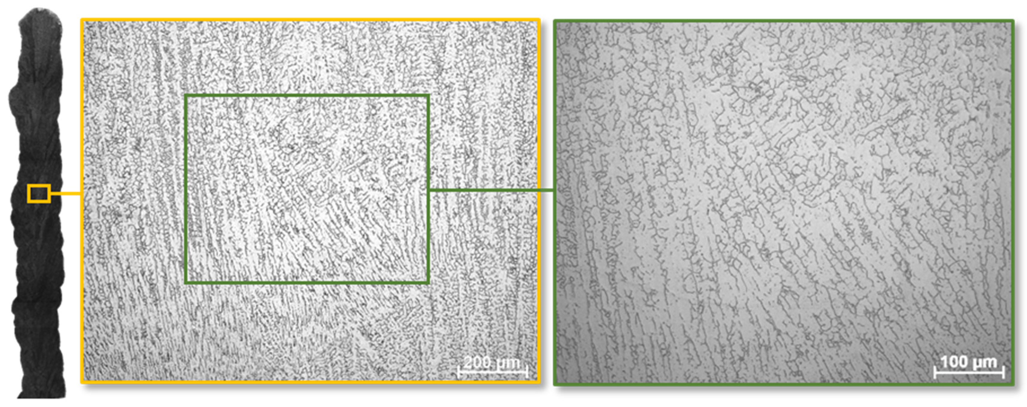
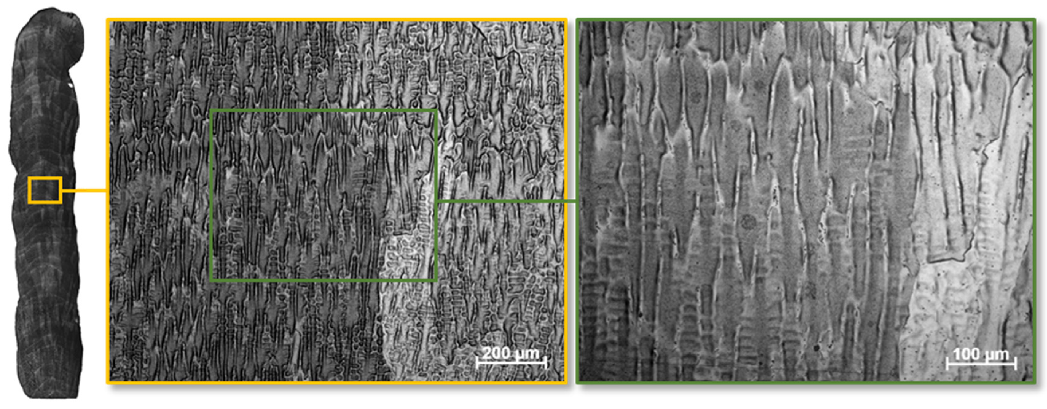
2.2. Initial State of the Microstructure
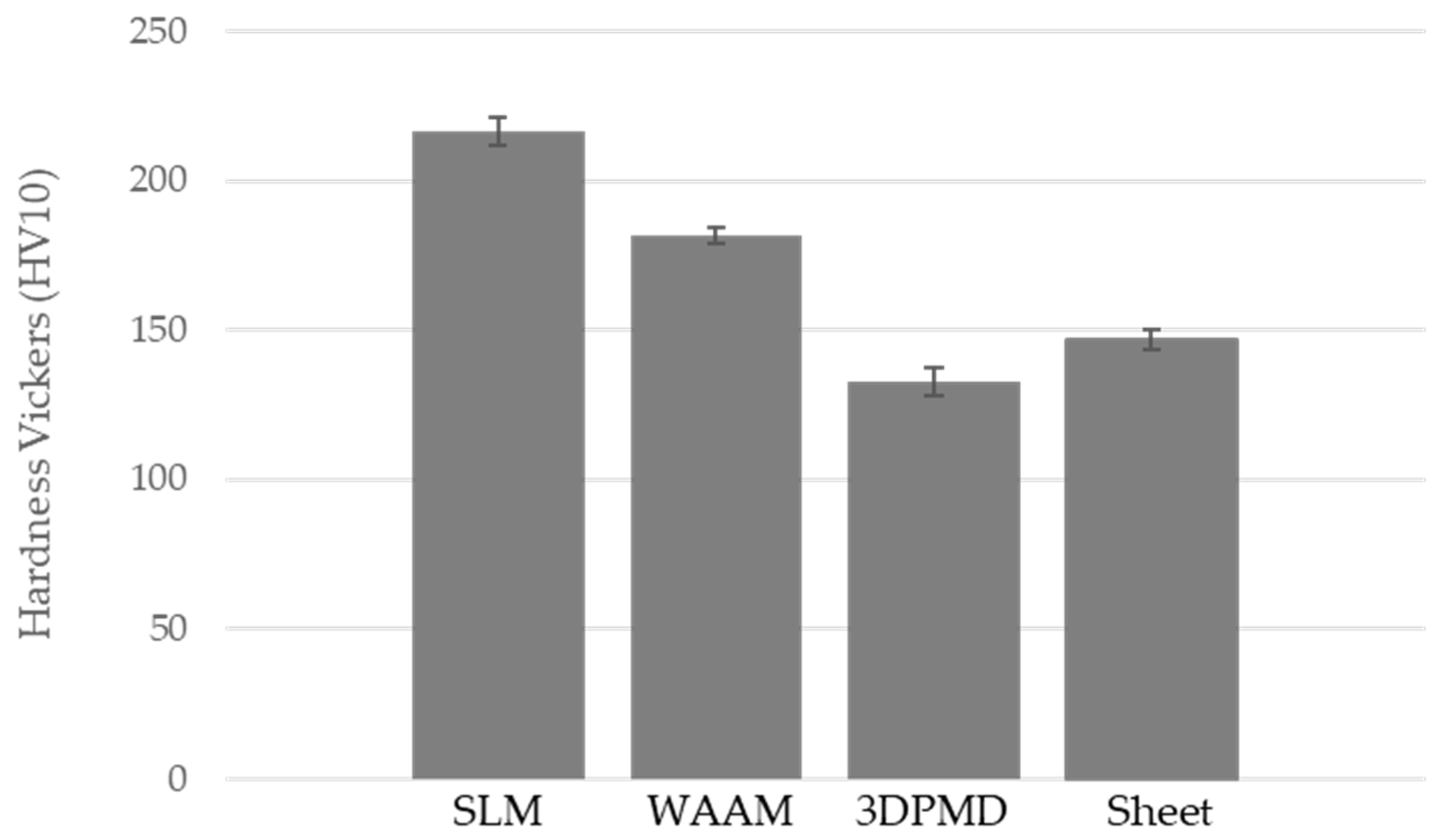
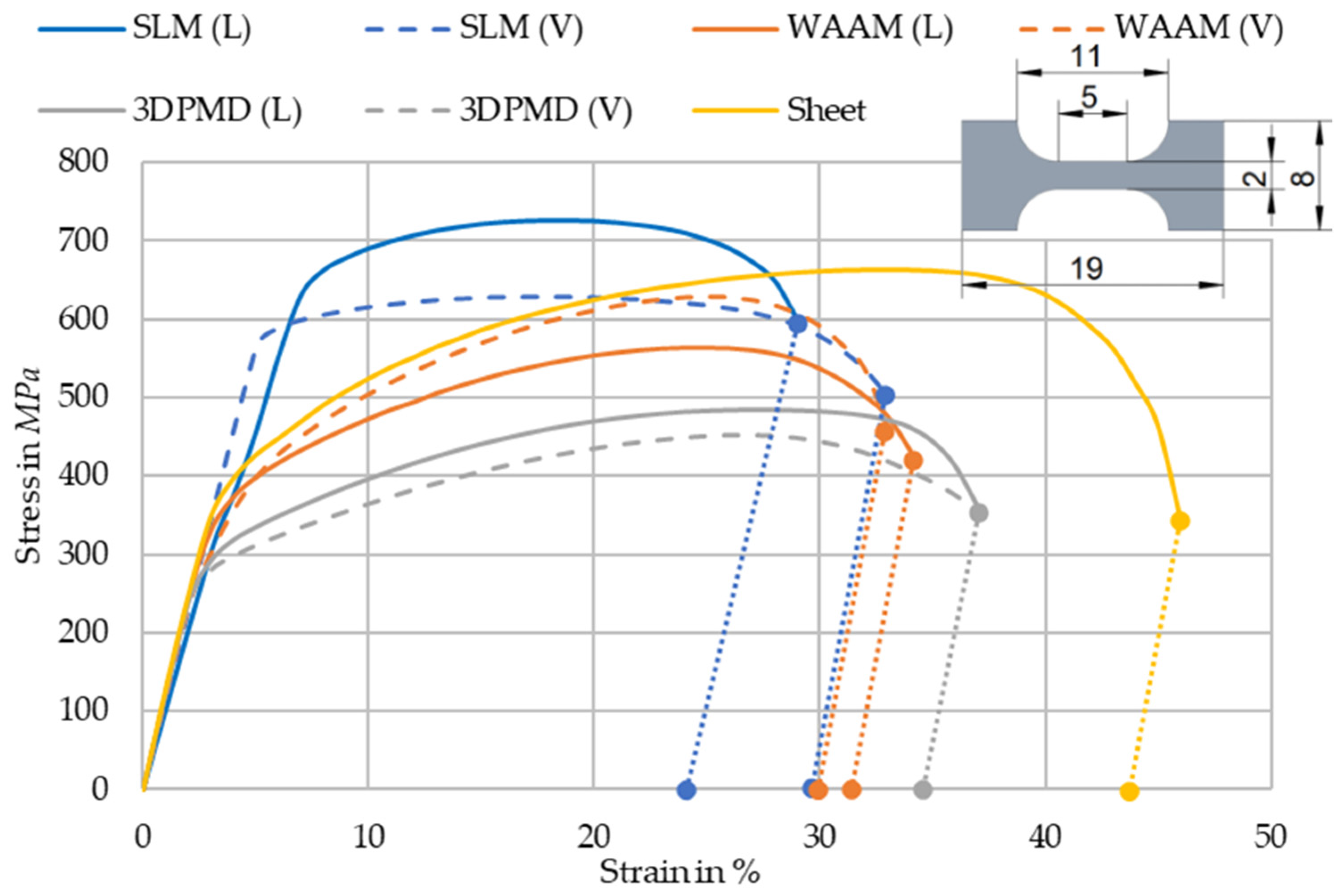
2.3. Mechanical Properties of the Reference Component
3. Experimental Investigation
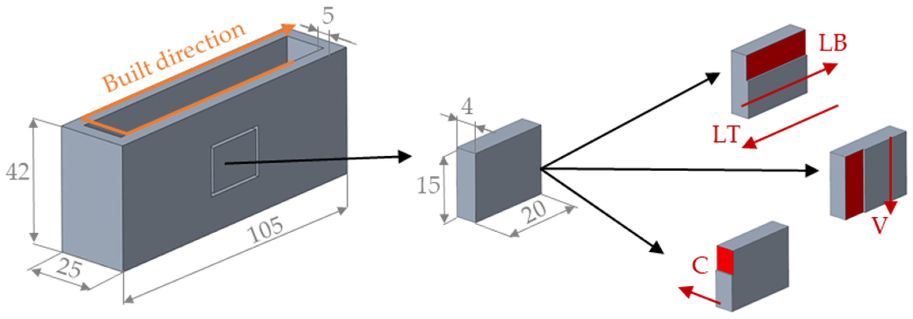
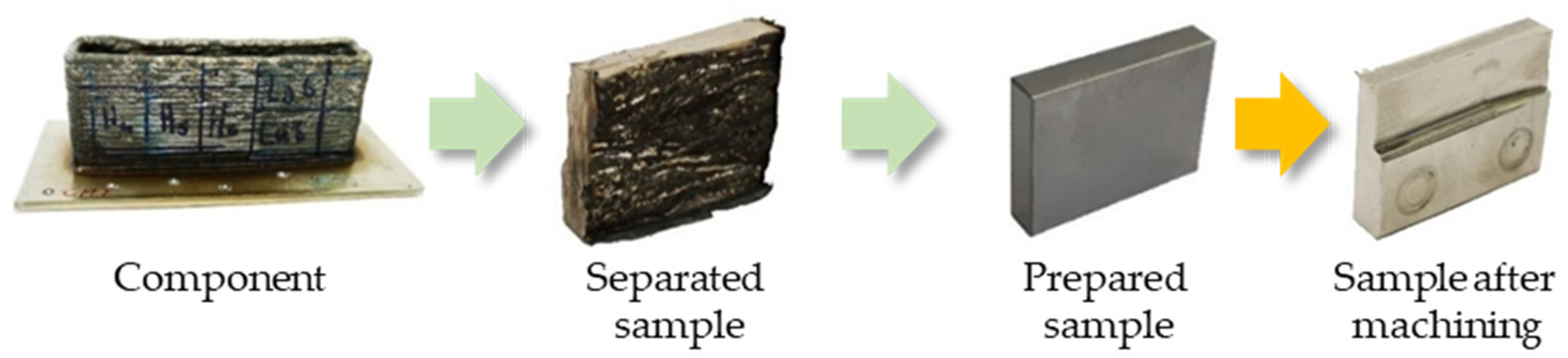
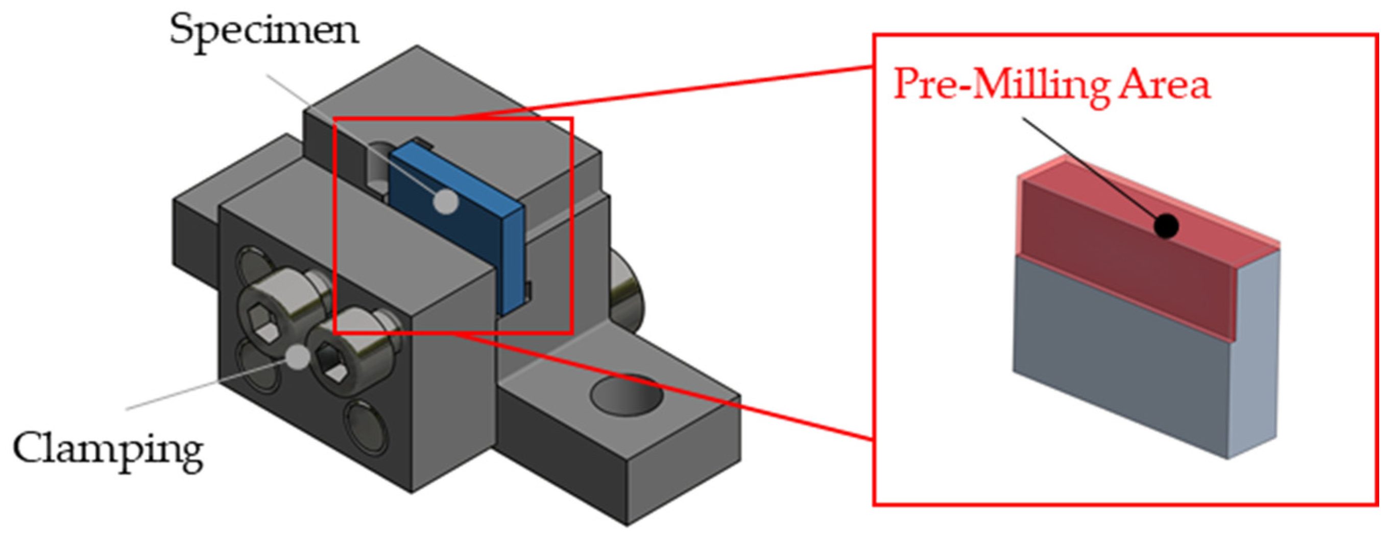
3.1. Sample Preparation
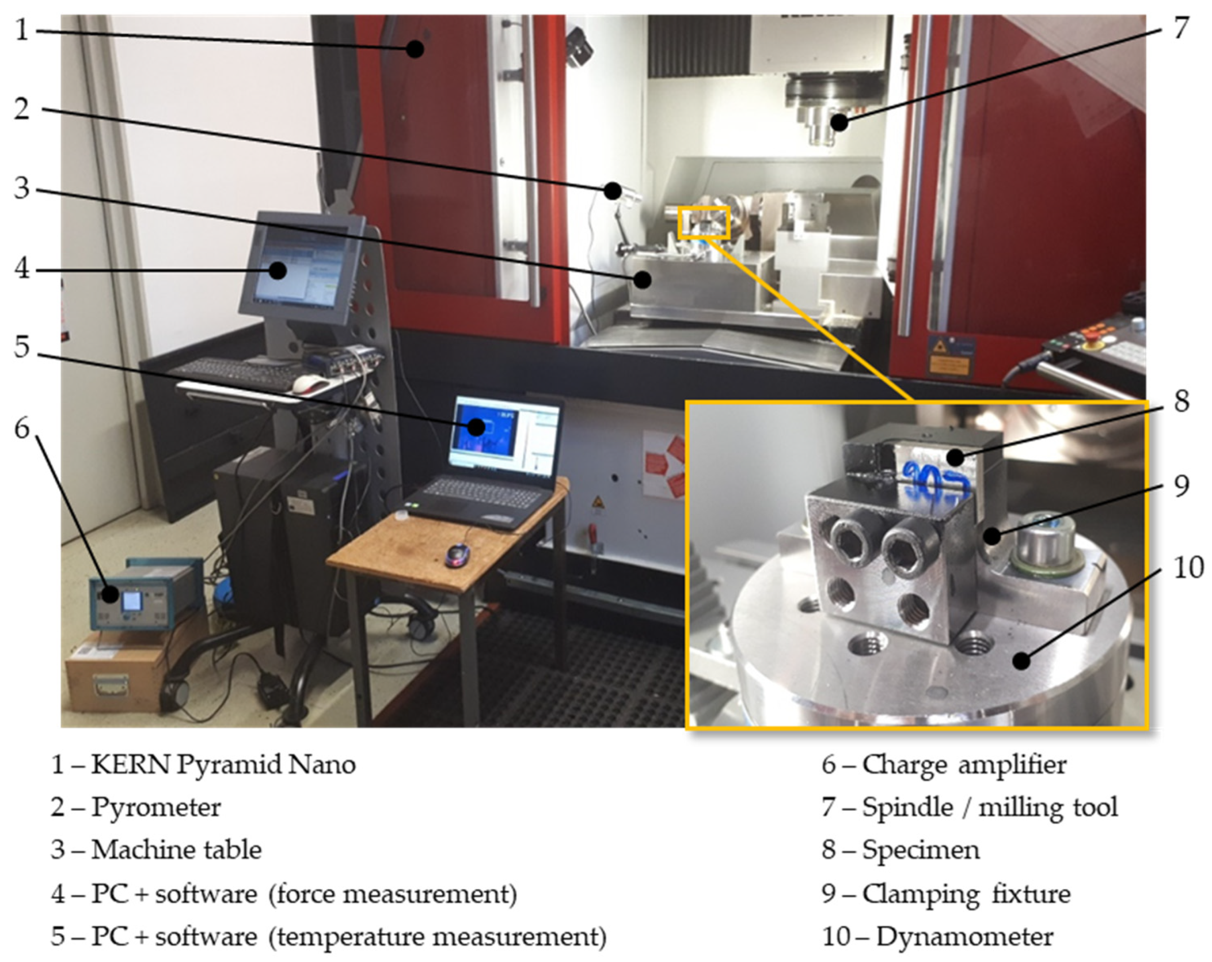
3.2. Experimental Set-Up
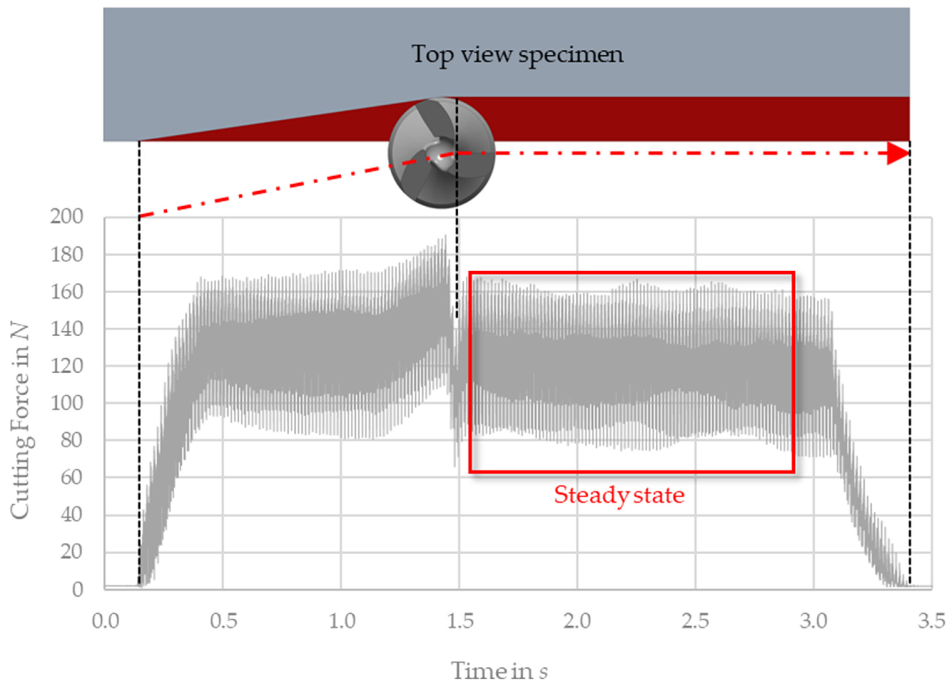
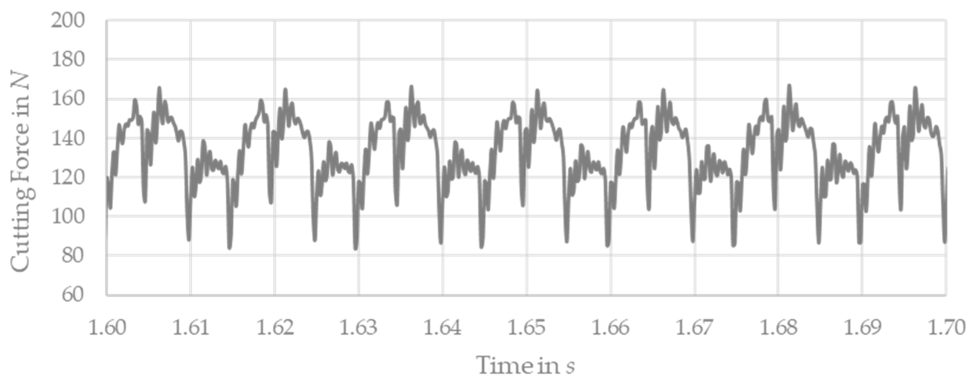
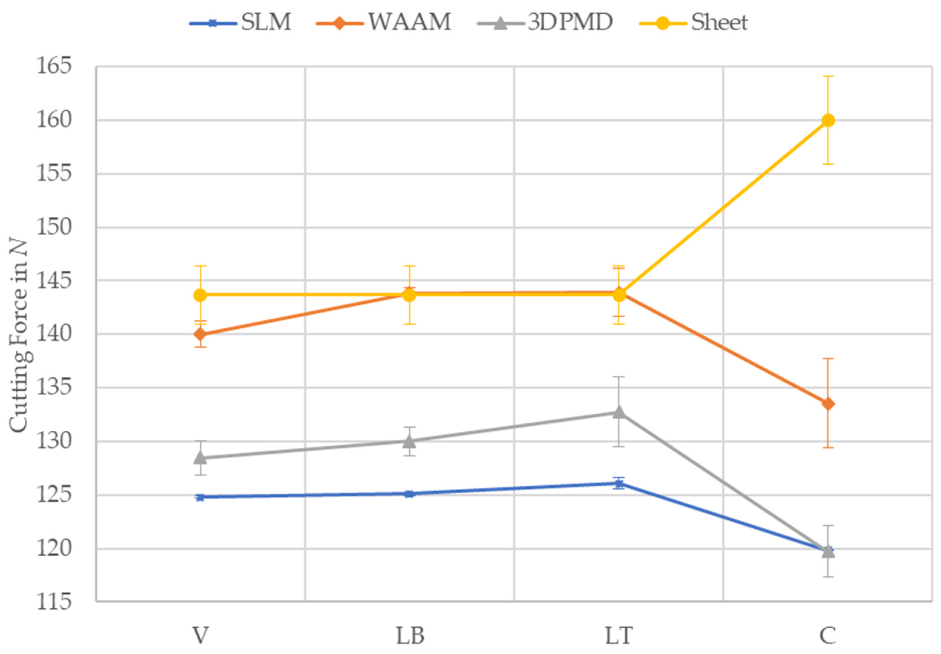
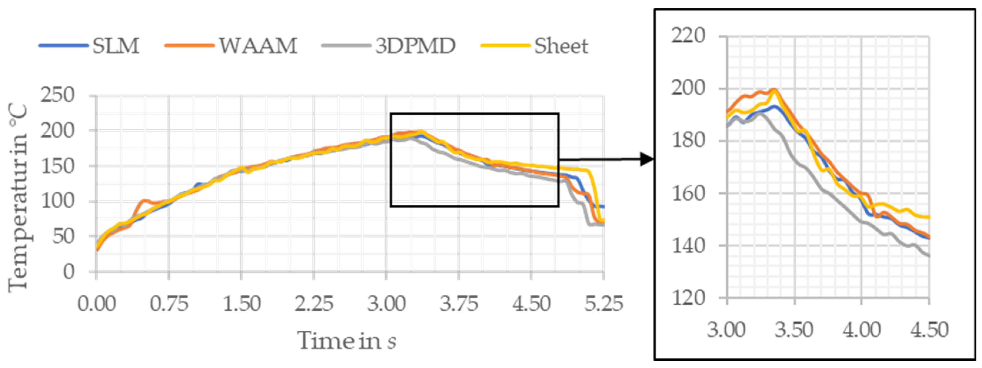
3.3. Measurement Results
4. Discussion
5. Summary and Outlook
Author Contributions
Funding
Institutional Review Board Statement
Informed Consent Statement
Data Availability Statement
Acknowledgments
Conflicts of Interest
References
- Smartech Analysis, 2020 Additive Manufacturing Market Outlook. Available online: www.smartechanalysis.com/news/2019-additive-manufacturing-market-growth/ (accessed on 29 April 2022).
- Hoefer, K.; Haelsig, A.; Mayr, P. Arc-based additive manufacturing of steel components—comparison of wire- and powder-based variants. Weld World 2018, 62, 243–247. [Google Scholar] [CrossRef]
- Oyelola, O.; Crawforth, P.; M’Saoubi, R.; Clare, A.T. Machining of Additively Manufactured Parts: Implications for Surface Integrity. Procedia CIRP 2016, 45, 119–122. [Google Scholar] [CrossRef]
- Khanna, N.; Zadafiya, K.; Patel, T.; Kaynak, Y.; Rashid, R.A.R.; Vafadar, A. Review on machining of additively manufactured nickel and titanium alloys. J. Mater. Res. Technol. 2021, 15, 3192–3221. [Google Scholar] [CrossRef]
- Montevecchi, F.; Grossi, N.; Takagi, H.; Scippa, A.; Sasahara, H.; Campatelli, G. Cutting Forces Analysis in Additive Manufactured AISI H13 Alloy. Procedia CIRP 2016, 46, 476–479. [Google Scholar] [CrossRef] [Green Version]
- Gong, Y.; Li, P. Analysis of tool wear performance and surface quality in post milling of additive manufactured 316L stainless steel. J. Mech. Sci. Technol. 2019, 33, 2387–2395. [Google Scholar] [CrossRef]
- Vayre, B.; Vignat, F.; Villeneuve, F. Metallic additive manufacturing: State-of-the-art review and prospects. Mech. Ind. 2012, 13, 89–96. [Google Scholar] [CrossRef]
- Greco, S.; Kieren-Ehses, S.; Kirsch, B.; Aurich, J.C. Micro milling of additively manufactured AISI 316L: Impact of the layerwise microstructure on the process results. Int. J. Adv. Manuf. Technol. 2021, 112, 361–373. [Google Scholar] [CrossRef]
- Lopes, J.G.; Machado, C.M.; Duarte, V.R.; Rodrigues, T.A.; Santos, T.G.; Oliveira, J.P. Effect of milling parameters on HSLA steel parts produced by Wire and Arc Additive Manufacturing (WAAM). J. Manuf. Processes 2020, 59, 739–749. [Google Scholar] [CrossRef]
- Brandl, E.; Baufeld, B.; Leyens, C.; Gault, R. Additive manufactured Ti-6Al-4V using welding wire: Comparison of laser and arc beam deposition and evaluation with respect to aerospace material specifications. Phys. Procedia 2010, 5, 595–606. [Google Scholar] [CrossRef] [Green Version]
- Taufek, T.; Manurung, Y.H.P.; Lüder, S.; Graf, M.; Salleh, F.M. Distortion Analysis of SLM Product of SS316L using Inherent Strain Method. IOP Conf. Ser. Mater. Sci. Eng. 2020, 834, 12011. [Google Scholar] [CrossRef]
- Lewandowski, J.J.; Seifi, M. Metal Additive Manufacturing: A Review of Mechanical Properties. Annu. Rev. Mater. Res. 2016, 46, 151–186. [Google Scholar] [CrossRef] [Green Version]
- Pan, Z.; Feng, Y.; Liang, S.Y. Material microstructure affected machining: A review. Manuf. Rev. 2017, 4, 5. [Google Scholar] [CrossRef] [Green Version]
- Colditz, P.; Graf, M.; Hälsig, A.; Härtel, S.; Prajadhiama, K.P.; Manurung, Y.P.; Awiszus, B. Experimental Investigation of Different WAAM (Wire-Arc Additive Manufacturing) Processes and Their Influence on the Component Properties and Formability. In The Minerals, Metals & Materials Series, Forming the Future; Daehn, G., Cao, J., Kinsey, B., Tekkaya, E., Vivek, A., Yoshida, Y., Eds.; Springer International Publishing: Cham, Switzerland, 2021; pp. 2853–2865. [Google Scholar]
- Giertler, A. Mechanismen der Rissentstehung und -Ausbreitung im Vergütungsstahl 50CrMo4 bei sehr Hohen Lastspielzahlen; Berichte aus dem Institut für Eisenhüttenkunde: Aachen, Germany, 2020. [Google Scholar]


| Manufacturing Process | SLM | WAAM | 3DPDM | Sheet Metal |
|---|---|---|---|---|
| Material | 316L (1.4403) | |||
| Initial state | Powder (30–63 µm) | Wire (Ø 1.2 mm) | Powder (50–125 µm) | Sheet (cold rolled) |
| Melting source | Laser | Arc | Arc | - |
| Layer height/sheet thickness | 0.06 mm | 1.70 mm | 0.97 mm | 6.00 mm |
| Process time/reference component | 231.3 min | 13.5 min | 22.5 min | Not specified |
| Reference component |  | 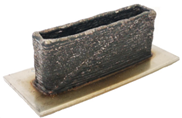 | 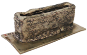 | 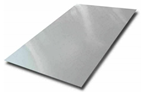 |
| SLM | WAAM | 3DPMD | Sheet Metal | |
|---|---|---|---|---|
| Microstructure | Lenticular | Dendritic | Elongated | Homogeneous |
| Hardness | ++ | + | − − | − |
| Tensile strength | + | − | − − | − |
| Elongation at break | − − | − | + | ++ |
| Force during milling | − − | + | − | + |
| Temperature | + | + | − | + |
| Surface roughness | − | − | − | − |
Publisher’s Note: MDPI stays neutral with regard to jurisdictional claims in published maps and institutional affiliations. |
© 2022 by the authors. Licensee MDPI, Basel, Switzerland. This article is an open access article distributed under the terms and conditions of the Creative Commons Attribution (CC BY) license (https://creativecommons.org/licenses/by/4.0/).
Share and Cite
Laue, R.; Colditz, P.; Möckel, M.; Awiszus, B. Study on the Milling of Additive Manufactured Components. Metals 2022, 12, 1167. https://doi.org/10.3390/met12071167
Laue R, Colditz P, Möckel M, Awiszus B. Study on the Milling of Additive Manufactured Components. Metals. 2022; 12(7):1167. https://doi.org/10.3390/met12071167
Chicago/Turabian StyleLaue, Robert, Pascal Colditz, Manuel Möckel, and Birgit Awiszus. 2022. "Study on the Milling of Additive Manufactured Components" Metals 12, no. 7: 1167. https://doi.org/10.3390/met12071167
APA StyleLaue, R., Colditz, P., Möckel, M., & Awiszus, B. (2022). Study on the Milling of Additive Manufactured Components. Metals, 12(7), 1167. https://doi.org/10.3390/met12071167