Review

A Review of Laser Peening Methods for Single Crystal Ni-Based Superalloys

Department of Mechanical Engineering, The University of Alabama, Tuscaloosa, AL 35487, USA
*
Author to whom correspondence should be addressed.
Metals 2022, 12(9), 1414; https://doi.org/10.3390/met12091414
Submission received: 5 July 2022 / Revised: 18 August 2022 / Accepted: 22 August 2022 / Published: 26 August 2022
(This article belongs to the Special Issue Processing Impact on Functional Metals)

Abstract

:
Single crystal Ni-based superalloys are often used to create gas turbine engine blades for their high strength under intense thermo-mechanical loading. Though they are remarkably capable under these conditions, a particular class of premature failure mechanisms known as surface-initiated damage mechanisms can lead to the early fracture of an otherwise healthy blade. This review paper discusses the current progress of post-processing techniques that can greatly mitigate the potency of surface-initiated damage mechanisms. In particular, laser peening (LP) is of significant interest due to the relatively low amount of cold work it induces, greater depth of compressive residual stresses than other cold working methods, ability to accommodate complex part geometries, and the minuscule effect it has on surface roughness. The residual stresses imparted by LP can greatly hinder crack growth and consequently allow for enhanced fatigue life. Given that turbine blades (constructed with single crystal Ni-based superalloys) are prone to fail by these mechanisms, LP could be a worthy choice for increasing their service lives. For this reason, initiative has been taken to better understand the mechanical and microstructural modifications imparted by LP on single crystal Ni-based superalloys and a summary of these investigations are presented in this review. Results from several works show that this class of alloy responds well to LP treatment with improvements such as ~30–50% increase in microhardness, 72% increase in low cycle fatigue life, and elevated resistance to hot corrosion. The primary objective of this review is to provide insight into current state-of-the-art LP techniques and summarize the findings of numerous works which have utilized LP for increasing the service lives of single crystal Ni-based superalloy components.

1. Introduction

With the rise in global temperatures threatening to cause catastrophic damage around the globe, it is imperative that human-generated carbon emissions be reduced. One engineering solution is to convert current fossil-fuel consuming processes to alternative processes which rely upon sustainable fuel sources. While renewable energy will certainly be ubiquitous in the future, current sustainable fuel technologies are in many cases less cost-effective than their fossil fuel counterparts. This is particularly problematic for aircraft, which account for 2% of global carbon emissions [1] but benefit highly from the lightweight, economical, and relatively simple design of their gas turbine jet engines. Whilst a long-term solution for sustainable air travel may be many years away, a stopgap measure for the present-day lies in the extraction of greater efficiency from existing engines by operating at higher combustion chamber temperatures such that less fuel is consumed, and fewer carbon emissions are generated with each flight. Unfortunately, higher operating temperatures subject critical engine components, such as turbine blades, to much more intense thermomechanical loads. State-of-the-art Ni-based superalloys including PW1484, Rene N5, and the CMSX series are choice materials for turbine blade applications but are limited to operating temperatures below 1100 °C. When higher combustion temperatures are desired, the turbine blades are coated with “thermal barrier coatings” (TBC) which allow for operation up to 1500 °C. Additionally, channels within the blades allow for the circulation of coolant which removes heat and enables even higher combustion chamber temperatures, though at the expense of efficiency. Aside from TBCs and coolant channels, there is little more that can be done from a materials engineering perspective to extend the lives of turbine blades. Consequently, there is great demand for novel manufacturing techniques to improve the mechanical strength of single crystal Ni-based superalloys beyond what is currently possible.
The objective of this review is to provide a thorough discussion of a versatile surface hardening technique for use in single crystal Ni-based superalloy manufacturing known as laser peening. To the best of the authors’ knowledge, such a review does not currently exist and great care was taken in accurately representing the contributions of the reviewed works to the surface engineering field.

1.1. Surface Enhancement Techniques
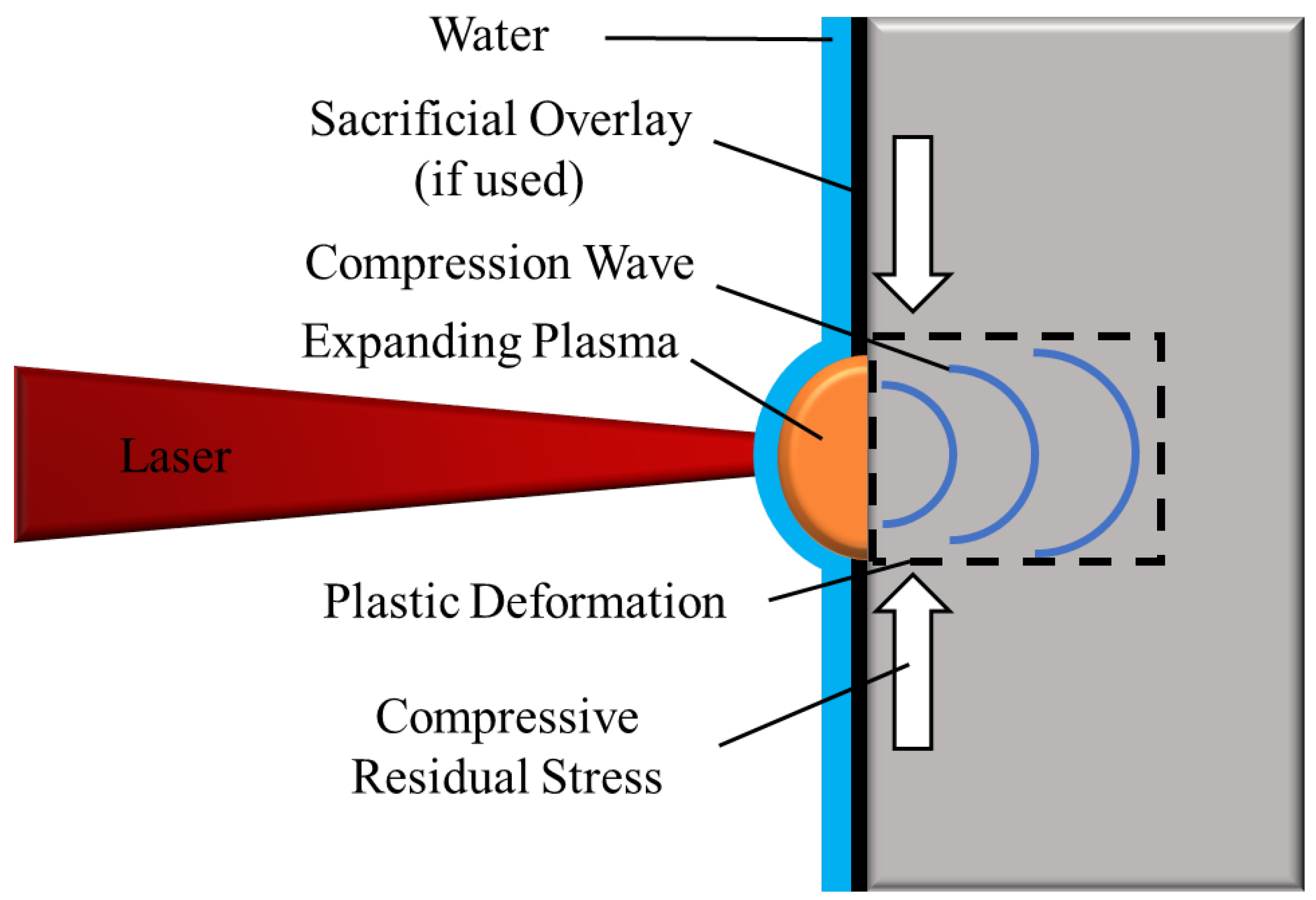
The microstructures of single crystal Ni-based superalloys have been optimized to such a large degree that there remains very little room for further improvement in terms of alloying or casting methods. However, post-processing techniques such as shot peening [2], low plasticity burnishing [2], and laser peening [3] offer enhanced strength against surface-initiated damage mechanisms such as foreign object damage, fatigue, and hot corrosion cracking, which are often a source of early failure in turbine blades. These processes allow for the components to maintain their bulk material properties while having enhanced defense against failure originating from the surface.
Shot peening is perhaps the most popular surface enhancement technique due to its relatively simple procedure and ability to substantially improve mechanical properties. In a typical shot peening procedure, the workpiece is blasted with a hard (usually metal) ball, or shot. The impacts from the shots create localized plastic deformation at the surface as well as residual stresses due to the interactions of elastic and inelastic straining in the material. One of the benefits of inducing a compressive residual stress state at the surface is that the required stress level for crack growth increases, and consequently, fatigue life is extended. The use of shot peening in single crystal Ni-based superalloys to enhance their fatigue performance has been studied by [2,4,5,6,7,8]. The primary drawback of shot peening though is the effect it has on the surface roughness due to the impact craters left behind by the shots which can act as crack nucleation sites. Additionally, the residual stresses tend to relax nearly entirely at typical turbine blade operating temperatures. While the benefits of shot peening are certainly attractive, the degradation of surface quality associated with it has led to research into other post processing methods which can offer similar surface hardening techniques while limiting any dimensional changes to the high tolerance components. A potential solution lies in another surface enhancement technique known as deep cold rolling (DCR) which utilizes the pressure input from a hydrostatic bearing rather than a shot media. This effectively provides a smoother surface following treatment than shot peening while still imparting beneficial compressive residual stresses and surface hardening effects [2,9,10,11]. Additionally, DCR is known to introduce less cold work than shot peening which enables higher stability of residual stresses under high temperature exposure [12,13]. The primary drawback of DCR, however, is that it requires highly specific part geometries which greatly limits its applicability to the complex contours of turbine engine components [14]. Thus, for the treatment of turbine blades, there is a need for a post processing technique which induces a high magnitude of compressive residual stresses that also has a minimal effect on surface roughness, creates a low amount of cold work, and can accommodate complex part geometries. Fortunately, a technique known as LP, or laser shock peening (LSP), can accomplish all of these tasks.

1.2. Laser Peening

Lasers have shown their use in numerous manufacturing applications such as additive manufacturing [15,16,17,18], laser drilling [19,20], laser remelting [21,22], etc. LP is one such manufacturing process which operates by very similar mechanisms as other, more traditional, peening processes with the additional benefits provided by the functionality and flexibility of laser technology. However, instead of using the blunt force of a hammer or metal shot, LP uses a laser, focused to a roughly 1–4 mm diameter circular (or rectangular) spot to strike the incident material and immediately heat the surface at the point of impact to a plasma. It must be emphasized at this point that although LP involves generating plasma, the heat does not affect the material any deeper than a few microns and is therefore not regarded as a thermal process, in contrast with processes such as direct metal laser sintering [23]. The plasma expands outward which generates a pressure pulse that propagates into the bulk material; attenuating with depth as it travels (Figure 1). So long as the pressure wave remains above the material’s Hugoniot Elastic Limit (HEL) which is a function of dynamic yield stress (σdyn) and Poisson’s ratio (ν), plastic deformation is induced.
H E L = 1 ν 1 2 ν σ d y n
The effectiveness of LP is controlled by several input parameters including spot size and overlap, number of successive shots, laser wavelength, laser pulse duration, laser power density, the use of a sacrificial overlay, and the use of a confining media [24]. Laser power density is directly related to the peak plasma pressure, which in turn controls the magnitude of plastic deformation and compressive residual stresses. Peak pressure has been experimentally shown to correlate approximately linearly with plastic strain and achieves a maximum value between 2 and 2.5 times the HEL of the material [25].
It then follows that the laser power density should be chosen such that a pressure pulse of a magnitude between 2 and 2.5 HEL is generated for peak plastic strain and peak compressive residual stress. Equation (2) describes the analytical relationship between the peak value of pressure pulse ‘P’, the reduced shock impedance of the target material ‘Z’, the ratio of laser energy used to create the plasma to the total laser energy (typically ~0.4) ‘α’, and the laser power density ‘Io [26].
P = 0.01 α 2 α + 3 · Z · I o
Although using an optimal peak pressure will generate a high magnitude of compressive stresses, the depth to which a residual stress state is developed may be quite shallow after a single shot depending on the material chosen. Equations (3)–(5) describe the analytical relationship between the depth of plastic deformation ‘ L p ’, HEL, peak pressure ‘P’, elastic wave speed ‘Cel’, plastic wave speed ‘Cpl’, Elastic Modulus ‘E’ and pulse width ‘τ’. In the case that a greater depth of plastic deformation is desired, additional shots in the same location can be applied successively to drive the residual stresses deeper into the material [25,27].
L p = C e l C p l τ C p l C e l P + H E L 2 H E L
C e l = E ρ 1 ν 1 + ν 1 2 ν
C p l = E ρ 1 3 1 2 ν
Another influential process parameter in LP is the use of a sacrificial overlay (usually black paint or tape). As described previously, the surface of the material is heated rapidly into a plasma upon interaction with the laser. The rapid expansion of this plasma creates a pressure pulse that is driven deep into the target material (Figure 1). However, by using a sacrificial overlay, the surface of the material is spared from absorbing the laser energy as the black paint or tape is converted into plasma instead. Consequently, there is very little change in roughness and no resolidified layer present following LP. Additionally, it has been reported that the sacrificial overlay can aid in plasma formation and consequently result in higher magnitude pressure pulses, though this effect is highly material dependent and is usually only observed at lower laser power densities [28,29].
The process as it has been described so far is known as direct ablation LP and is LP in its’ simplest form. The drawback of this method is that the pressure pulse is limited by the duration of the laser pulse. In an effort to extend the duration of the pressure pulse and consequently improve its effectiveness in deforming the incident material, a transparent confining layer of water (or sometimes glass or quartz) is used to restrict the expansion of the plasma and concentrate the pressure pulse at the point of impact. This confinement layer typically increases the pressure pulse duration by 2–5 times and can increase the peak pressure up to 10 times under certain operating conditions [30]. Although the confining media is transparent and should not interact with the laser pulse, its presence is considered analytically by modifying the reduced shock impedance ‘Z’ value in Equation (2) to,
2 Z = 1 Z t a r g e t + 1 Z c o n f i n e
where Z t a r g e t and Z c o n f i n e are the reduced shock impedance values for the target material and the confining layer respectively. Utilizing a confinement layer has little effect on processing time as it often involves simply running water over the workpiece during the treatment and thus confined ablation is often preferred over direct ablation in an industrial setting. Henceforth, the LP works in this summary report are assumed to be conducted in confined ablation mode unless otherwise stated.

1.3. Microstructure of Single Crystal Ni-Based Superalloys

While laser parameters can be adjusted to tune the magnitude of impact, one must also consider the material being treated as the mechanisms by which it responds to the LP treatment are largely governed by its microstructural features. Single crystal Ni-based superalloys are known for their excellent mechanical strength and oxidation resistance at high temperatures, making them a choice material for high-performance turbine blades (Figure 2a). The mechanical properties of these alloys are largely attributed to a microstructure comprised of ordered cuboidal L12 γ’ precipitates (~70% volume fraction) embedded coherently within a disordered continuous γ matrix (Figure 2c). The coherency at the γ/γ’ interface is not perfect however and causes a degree of misfit strain which can either be negative (compressive stress in the γ channels and tensile stress in the γ’ precipitates) or positive (tensile stress in the γ channels and compressive stress in the γ’ precipitates) (Figure 2d). The γ/γ’ dominated microstructure makes up a larger dendritic structure (Figure 2b) which is a result of the directional solidification process by which it was cast and causes anisotropic mechanical properties. In the case of turbine blades, this anisotropy is favorable as the dendrites are grown such that the blades are strongest in the loading direction [31]. While the cores of the dendrites contain a uniform spread of fine cuboidal γ’ precipitates, the eutectic regions between dendrites contain bloated, non-coherent γ’ phases and are associated with decreased strength [31].

2. Laser Peening of Single Crystal Ni-Based Superalloys

The surface mechanical property enhancements generated by LP improve resistance to surface-initiated damage mechanisms such as fatigue [33,34,35,36,37], foreign-object damage [38,39,40], and stress corrosion cracking [41,42,43,44] in a number of aerospace-grade alloys. Turbine blades (which are typically constructed from single crystal Ni-based superalloys) are particularly prone to failure by these mechanisms due to the intense thermomechanical loads and corrosive effects of the combustion products. Given that LP is a proven method for mitigating these failure mechanisms, experimental work has been undertaken to understand its effectiveness at enhancing the mechanical properties of these alloys. This section outlines the microhardness and residual stress changes associated with LP performed on single crystal Ni-based superalloys and the stability of these enhancements in the presence of high-temperature thermal exposure.

2.1. Microhardness Distribution Following LP

The primary means by which LP strengthens a material against surface-initiated damage mechanisms are compressive residual stresses and enhanced surface hardness. Figure 3a shows the microhardness distribution at various depths from the LP surface for a DD6 specimen treated with 3 layers at 5 GW/cm2 [45]. Following LP, the surface microhardness increased to ~635 HV from the baseline value of 425 HV (a 50% improvement) and continued up to a depth of 1 mm where it eventually regressed back to the baseline value. In addition, the LPed specimens were placed in a furnace to determine the thermal stability of the elevated hardness. After 1 h at 950 °C, surface microhardness decreased to 525 HV and though this is still greater than the baseline sample, it is a significant reduction from the as-LPed specimens. After a 1200 °C exposure, the surface microhardness decayed to values below the baseline across the entire profile which was likely caused by the dissolution of γ’ precipitates, though the precise mechanism is unclear from this work.
An unfortunate downside of surface enhancement techniques such as LP is that their effectiveness is limited by the relaxation of dislocations and residual stresses at high temperatures. Thus, the initiative has been taken in the creation of modified LP treatments which include a heat treatment phase to maintain mechanical property improvements. Laser peening + thermal microstructure engineering (LP + TME) is one such method which incorporates annealing stages between layers of LP [46,47]. Recently, Munther et al. reported that LP+TME implemented on additively manufactured Inconel 718 yielded 58% higher compressive residual stresses following a 350 h exposure to 600 °C (0.5 Tm of Inconel 718) than a sample treated with LP [46]. As previously discussed, residual stresses induced by LP typically relax at high temperatures but in LP+TME, relaxation is greatly mitigated. Additionally, surface hardness was 5% higher following the LP+TME treatment than the LP treatment and only decreased by 3% after high-temperature exposure. The thermal stability is attributed to the nucleation and growth of precipitates within the dislocation structures generated by LP. These precipitates acted as pinning points on the dislocations and restricted their movement. Additional evidence of precipitate-dislocation interactions including Friedel cutting and Orowan bypassing were observed which also likely contributed to the increased retention of plastic strain. Early results from LP+TME experiments show its promise as a process for extending the operating temperature range for LPed components, though it has yet to be tested on single crystalline superalloys.
Another modified LP treatment known as warm laser shock peening (WLSP), or LP performed at elevated temperatures, was conducted by Tang et al. on single crystal Ni-based superalloy, DD6 [48]. The hypothesis behind this variant of LP is that thermally stable dislocation networks can be created by inducing dynamic strain aging (DSA) effects. Following WLSP, the authors observed a surface microhardness increase of approximately 31–37% over the baseline (Figure 3b). They attributed the microhardness increase to residual stresses within the lattice which altered the resistance of the material to local deformation. Additionally, they found that increasing the WLSP working temperature had a positive correlation with microhardness which indicates that the DSA mechanism had been activated. The findings from this work suggest that LP can be used to modify mechanical properties not only via inducing work hardening effects and residual stresses but additionally by activating new strengthening mechanisms which can pin dislocations created during the LP process.

2.2. Residual Stress Distribution and Measurement Following LP

As stated previously, compressive residual stresses are a key component in the overall strength enhancement provided by LP as they can greatly limit crack growth rates and improve resistance to surface-initiated damage mechanisms. The measurement of these stresses is therefore a very important metric, although it can be relatively challenging to measure in single crystalline Ni-based superalloys. Typically, powder diffraction techniques such as sin2 ψ or cos α are used for calculating stresses and strains via changes in interplanar spacings along specific planar axes in polycrystalline materials. In the case of the sin2ψ technique, diffraction data are collected at several angles of ψ, whereas the cos α technique makes use of an area detector that collects diffraction data (Debye-Scherrer ring) from a single X-ray beam, allowing for more expedient collection times [49,50,51]. While these techniques are used extensively for residual stress calculation of polycrystalline materials, they are rarely used for single crystalline materials due to additional experimental complexity associated with differences in diffraction behavior [45]. Because of this, an alternative XRD method is often utilized in which the peak shift corresponding to a specific diffraction plane is measured and subsequently converted into strain and stress values [45,52,53] The diffraction peaks for both the γ and γ’ phases corresponding to a given (hkl) plane were collected and their Bragg angles were converted to d-spacings by Bragg’s law,
n λ = 2 d h k l sin θ
where λ is X-ray wavelength, d h k l is the interplanar spacing of the (200) plane, θ is Bragg Angle corresponding to the given (hkl) peak, and n is the diffraction order. After separation, the peak centered around a higher Bragg Angle corresponds to the γ’ phase while the peak centered around a lower Bragg angle corresponds to the γ phase. Next, the residual stress σ in each phase is determined by the relationship outlined in [54],
σ = E v d h k l 1 d h k l 0 d h k l 0  
where   v is Poisson’s ratio, d h k l 0 is the unstrained d-spacing for a given (hkl) plane, and d h k l 1 is the strained d-spacing. A weighted average is then taken using the diffraction peak intensities as weights to find the overall stress within the irradiated area by Equation (9),
σ a v g = I γ σ γ + I γ σ γ I γ + I γ
where σ a v g is the average residual stress in the area scanned by the XRD, I γ and I γ are the peak intensities of the γ and γ’ phases, respectively, and σ γ and σ γ are the residual stresses in the γ and γ’ phases respectively. Though simple and effective, this method can only provide an approximation of the residual stress state as the calculated value is only the sum of in-plane principle stresses and the out of plane stress vector is ignored [54]. It is possible that other methods such as hole drilling [55], neutron diffraction [56], or focused ion beam—digital image correlation [57] may provide more detailed quantitative data for stress measurement than XRD in LPed single crystal specimens, but there is limited discussion on this topic in the literature.
Figure 4a–c shows the diffraction peaks collected from the (311) plane of DD6 superalloy with the corresponding residual stress plot shown in Figure 4d [45]. Here, the residual stresses are clearly compressive with a maximum value nearest to the surface and attenuating with depth for the sample with no thermal exposure. Following a 1 h 950 °C and 1200 °C exposure, the surface residual stresses decrease by 13% and 30% respectively. As in the case of the microhardness decrease shown in Figure 3a, residual stresses are believed to have reduced in response to dislocation reorganization within the plastically deformed surface layer which allowed the elastic strain to partially relieve.
Although some degree of residual stress relaxation is expected, it is evident that enhancing dislocation pinning effects within the LP-affected microstructure is required to increase the thermal stability of plastic deformation and consequently, residual stresses. Tang et al. [53] treated DD6 with WLSP and measured the relaxation behavior following thermal exposure of 980 °C for 10 h (Figure 4e,f). Surface compressive residual stresses relaxed by ~15–17% in the WLSP specimens and around 30% for the LP specimen. The increased retention of stresses in the WLSP specimens is attributed to DSA effects which increased the energy barrier for dislocation movement. While the degree of relaxation is relatively mild in the WLSP specimens, (which certainly shows the promise of modified LP processes for use in turbine blade applications) the thermal exposure durations were limited in [45,53] and it is possible that with much longer exposure (comparable to the service life of a turbine blade), residual stresses may further decrease.

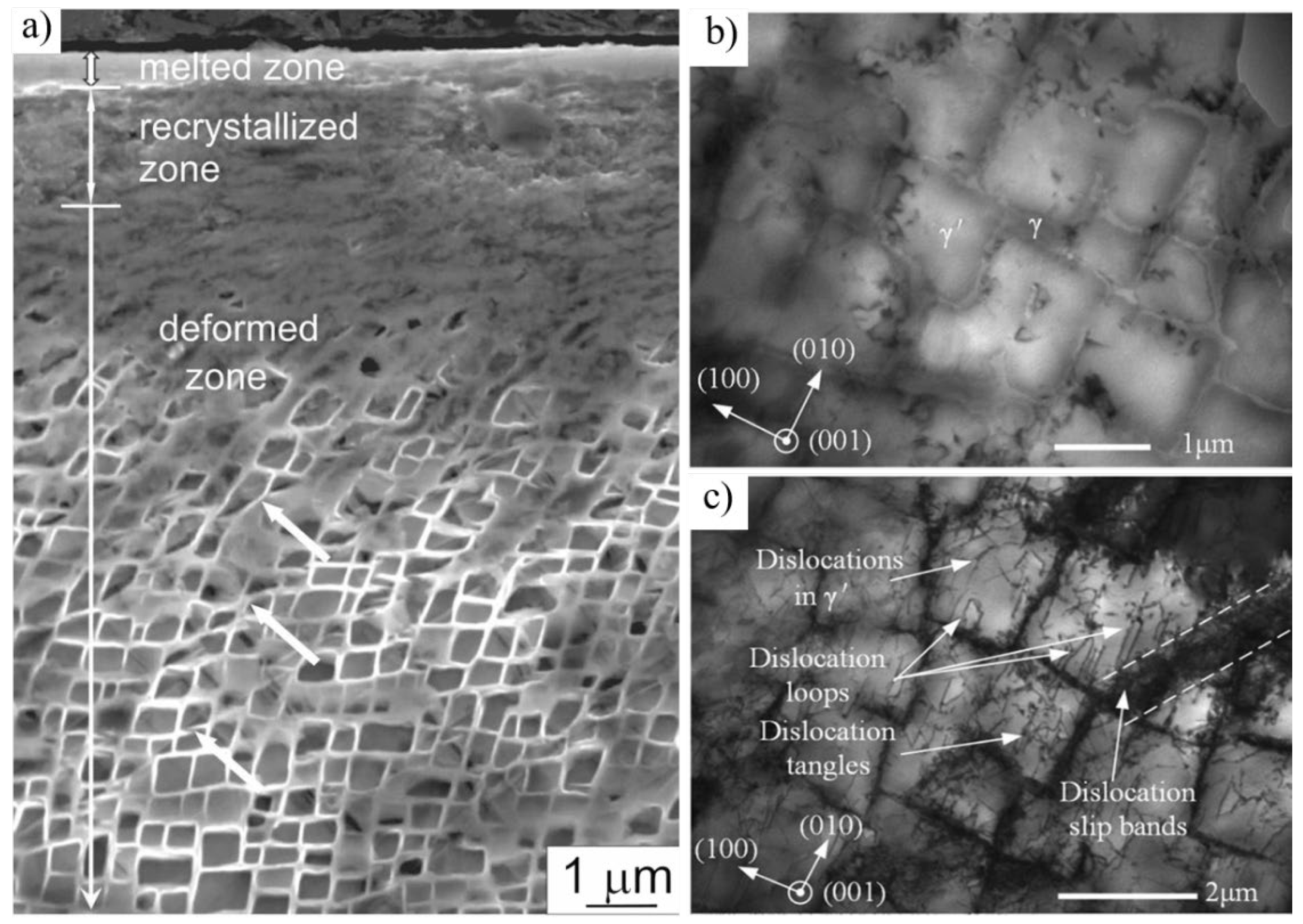
2.3. Microstructure Modifications Resulting from LP

Following LP, there are typically 3 distinct zones within the microstructure of single crystal Ni-based superalloys depending on processing conditions. As discussed previously, LP can be conducted with or without the use of a sacrificial ablative layer; and in the case of the latter, a layer of resolidified material (Figure 5a) rests on the surface and causes a distinct increase in roughness. This layer is conducive to crack initiation and is often removed via a subsequent process as it does not contribute to any strengthening enhancement. Directly under this layer, recrystallization can occur to a depth of roughly 1 µm due to the intense plastic deformation and corresponding large driving force to reduce strain energy within the crystal lattice. Given the single crystalline nature of this alloy class, the occurrence of recrystallization could be undesirable and therefore should be considered in the design of LP-based post processes. Additionally, the presence of slip bands was noted by several authors [5,45,58] in this region and was attributed to the formation of dislocation tangles which were able to overcome the critical shearing stress of the γ’ phases, and consequently initiate the slipping mechanism.
Traveling deeper into the material, the intensity of plastic deformation is reduced due to the attenuation of the compression wave and recrystallization is no longer present. Instead, the once cuboidal microstructure deforms into a less regular arrangement with heavily compressed γ’ surrounding the impact site (Figure 5a). As the pressure wave causes local distortions of the γ/γ’ microstructure, the γ’ precipitates are compressed normal to the direction of LP and the softer γ phase is pushed from the vertical channels into the horizontal channels [59] (Figure 6a,b). This precipitate morphology change was also noted by Tang et al. [48] who used the change in side length of γ’ phases as a secondary metric to determine the effectiveness of their modified LP treatment.
Figure 5c shows the dislocation-saturated microstructure of single crystal Ni-based superalloy DD6 after 3 layers of LP at ~5 GW/cm2 with the microstructure prior to treatment shown in Figure 5b. [45]. Dislocation slip primarily occurred along the 1 1 ¯ 1 plane with dislocations largely located in the γ phase, though dislocation loops and tangles within the γ’ phase were also noted. Due to the ordered nature of the γ’ phases, the shearing mechanism requires the passage of 2 dislocations, as the first creates an anti-phase boundary (APB) which must be restored. Thus, it is much more energetically favorable for a dislocation to glide through the disordered γ matrix phase than to shear through the precipitates. However, the accumulation of dislocations at the phase boundaries creates stress concentrations which reduces the critical shearing stress and allows dislocations to enter the γ’ precipitates.

2.4. Mechanical Property Evolution

Henceforth in this review, the discussion has centered around the microstructural and mechanical strengthening mechanisms generated by LP. However, the primary goal of LP is to use these enhancements to improve the treated material’s response to loads it will experience in aerospace applications. Turbine blades in particular are prone to damaging effects from hot corrosion fatigue due to the high-temperature combustion products that they are in contact with during operation [31]. SP [60,61] and LP [62,63] have been studied for their ability to reduce crack growth and thus slow hot corrosion fatigue. Figure 7a,b show cross-sectional SEM images of untreated and LPed single crystal Ni-based superalloy specimens along with corresponding energy dispersive spectroscopy (EDS) data following a hot corrosion test [52]. The baseline sample exhibited a topmost layer of hot corrosion products such as Ni-Co oxides, a middle layer of mixed oxides, and an innermost layer of γ’-free microstructure containing a fine dispersion of Al2O3 particles. While the LP sample exhibited a similar tri-layer corrosion structure, the extent to which corrosion affected each sample was significantly different. For example, the topmost layer in the baseline sample contained brittle oxide particles with very poor adhesion to the surrounding material which created spalling zones. In contrast, the LP-treated sample did not contain any brittle oxide particles nor spalling zones. In addition, the depth of corroded material from the surface was significantly lower in the LP specimen than in the untreated specimen. The primary reason for the differences in spalling behavior and corrosion depths is due to competitive oxide formation between Cr2O3 and Ta2O5 which have similar free energies of formation. In the case of the untreated specimen, neither oxide could overcome the other which led to a discontinuous oxide layer at the surface that did not aid in the passivation of further corrosion. In the LP specimen, the dislocations near the surface altered diffusion kinetics such that Cr could diffuse much faster and allow Cr2O3 to dominate growth and form a continuous layer. Additionally, an Al2O3 layer formed in both specimens under the mixed oxide layer due to the diffusion of Al out of the γ’ phases and into the surrounding matrix where it could react with oxygen and form its respective oxide. This corrosion behavior tracks well with [53] where the hot corrosion performance of WLSP treated DD6 was tested. The WLSP treated specimen contained a similar corrosion microstructure as the LP treated specimen but with a denser oxide layer and very few cracks or spalled areas. Additionally, the change in mass of all specimens was recorded after each of the six hot corrosion exposures and the corresponding data are presented in Figure 7c. The untreated specimen gained mass through the first four exposures, indicating a buildup of corrosion products, before dramatically losing mass in the fifth and sixth tests, indicating that the corroded material began shedding due to having poor adhesion. The LP specimen exhibited similar behavior, though far less dramatic with the mass remaining relatively constant after the fourth exposure. Lastly, the three WLSP specimens also gained mass throughout the six exposures but at a much slower rate, indicating that WLSP is more effective at delaying corrosion than the LPed and untreated specimens. The reasoning given by the authors is that the dislocation structures created via WLSP are more stable (due to DSA pinning effects) and distributed more evenly than the LP sample. Thus, dislocations were largely retained during the corrosion test for the WLSP specimen whereas dislocations may have partially relaxed in the LP specimen. As a result, the WLSP specimen had more dislocations to provide diffusion paths for Cr and Al atoms to react with O2 and form protective oxides Cr2O3 and Al2O3, respectively, (Figure 7d). This is in opposition of course to the untreated material which was unable to form a continuous layer of protective oxides and thus had very poor resistance to hot corrosion.
Surface defects such as spallation zones and pores can cause issues with fatigue performance due to the increased number of crack nucleation sites. Tang et al. tested the low cycle fatigue (LCF) performance of DD6 following WLSP to determine the effectiveness of the treatment at inhibiting crack nucleation and growth [64]. It was found that one layer of WLSP increased LCF life by 72% and three layers increased the life by 111%. The dramatic increase in LCF life was attributed to the compressive residual stresses and work hardened layer at the treated surface which decreased crack growth rates. The fracture surfaces of both the untreated and WLSP treated specimens are shown in Figure 8a,b and can be divided into three distinct regions: (1) fatigue source zone, (2) crack propagation zone, and (3) instantaneous fracture zone. In the fatigue source zone, WLSP treated specimens show a greater number of crack initiation sites which indicates that they spent much more time in the early stages of fatigue than the untreated specimen and consequently presented longer LCF lives [65]. In the crack propagation zone, fatigue striations are clearly present which is expected under fatigue loading. Additionally, this zone contains river marks which point to the direction of crack nucleation as well as its direction of travel. The WLSP treated specimens show far fewer river marks within the crack propagation zone in comparison to the untreated material which could indicate a difference in fracture mode. In contrast, Lu et al. [66] found no change in fracture mechanism under isothermal fatigue conditions following LP though as they reported that cracks formed from micropores rather than at the surface (Figure 8c,d). However, they do suppose that once a crack reaches the LP-affected zone, the compressive residual stresses inhibit its movement and thus prolong fatigue life.
Although the work on fatigue and corrosion behavior in single crystal Ni-based superalloys is limited, the vast amount of work conducted on polycrystalline Ni-based superalloys as well as the data from the reports reviewed here strongly suggest that LP is effective at enhancing resistance to surface-initiated damage mechanisms. However, there remains to be conclusive agreement regarding how the surface mechanical enhancements change at temperatures comparable to those experienced within a gas turbine engine. For this reason, it is suggested that future work study the thermal degradation (or lack thereof) in LPed single crystal Ni-based superalloy specimens as well as the engineering of microstructures following LP which can remain stable at temperatures at or above 0.5 Tm.

3. Conclusions

With the rise in global temperatures, it is clear that engineering processes must be improved such that carbon emissions are dramatically reduced. Unfortunately, efficiencies in processes such as combustion in gas turbine engines are limited by the high-temperature strength of currently available materials and manufacturing processes. While surface enhancement techniques such as shot peening and deep cold rolling have proven effective at increasing the fatigue life of Ni-based superalloys, there are difficulties associated with each process which make them challenging to implement for the treatment of turbine blades. LP is a highly versatile surface hardening technique which incorporates many of the benefits of SP and DCR with additional adaptability to complex part geometries, marginal effect on surface roughness, and low degree of cold work. LP for use in single crystal Ni-based superalloys is a relatively new field of study but early works show its ability to improve fatigue life and corrosion resistance by inducing deep compressive residual stresses and work hardening the surface layer. Notable findings from works discussed in this review include:
  • Increased microhardness at the treated surface by ~30–50% with enhancements extending ~1 mm into the surface.
  • LP was able to induce beneficial compressive residual stresses of ~300–600 MPa which significantly delayed crack propagation rates and improved fatigue life.
  • A 72% increase in LCF life over an untreated DD6 test specimen was observed following LP.
  • LP was shown to improve hot corrosion performance through the dislocation-assisted growth of protective oxides
Dislocation–dislocation, as well as dislocation-precipitate interactions, are responsible for resisting further deformation and/or reorganization of LP-generated defects, thus creating a metastable microstructure following LP. With the growing need for innovative processes such as LP which can enable single crystal Ni-based superalloys to withstand greater thermomechanical loads than currently possible, it is critical to understand the mechanistic origins of strengthening associated with LP in this class of alloy.

Author Contributions

Conceptualization, N.H.; investigation, N.H.; formal analysis, N.H.; writing—original draft preparation, N.H., K.D.; writing—review and editing, N.H. and K.D.; supervision, K.D.; funding acquisition, K.D. All authors have read and agreed to the published version of the manuscript.

Funding

The project was supported by the National Science Foundation, CMMI, Advanced Manufacturing Program (Award Number: 2029059).

Institutional Review Board Statement

Not applicable.

Informed Consent Statement

Not applicable.

Data Availability Statement

All data that support the findings of this study are included within the article.

Conflicts of Interest

On behalf of all authors, the corresponding author states that there is no conflict of interest.

References

  1. Aviation: Benefits Beyond Borders Global Report; Air Transportation Action Group: Geneva, Switzerland, 2020.
  2. Ehrl, J.; Polanetzki, H.; Hessert, R.; Wagner, L. Influence of mechanical surface strengthening on nickel-base superalloy DA718. In Proceedings of the 11th International Conference on Shot Peening, South Bend, IN, USA, 12–15 September 2011; 2011; pp. 213–218. [Google Scholar]
  3. Munther, M.; Martin, T.; Tajyar, A.; Hackel, L.; Beheshti, A.; Davami, K.; Kuenstner, S.; Li, D.; Titus, C. Laser shock peening and its effects on microstructure and properties of additively manufactured metal alloys: A review. Eng. Res. Express 2020, 2, 022001. [Google Scholar]
  4. Renzhi, W.; Zang, X.; Deyu, S.; Yuanfa, Y. Shot Peening of Superalloys and Its Fatigue Properties at Elevated Temperature. In Proceedings of the First International Conference on Shot Peening, Paris, France, 14–17 September 1981; pp. 395–403. [Google Scholar]
  5. Bogachev, I.; Knowles, K.M.; Gibson, G.J. Electron backscattered diffraction analysis of cold work in a shot peened single crystal nickel superalloy. Materialia 2020, 14, 100860. [Google Scholar]
  6. Buchanan, D.J.; John, R. Residual stress redistribution in shot peened samples subject to mechanical loading. Mater. Sci. Eng. A 2014, 615, 70–78. [Google Scholar]
  7. Hoffmeister, J.; Schulze, V.; Wanner, A.; Hessert, R.; Koenig, G. Thermal relaxation of residual stresses induced by shot peening in IN718. In Proceedings of the 10th International Conference of Shot Peening 2008, Tokyo, Japan, 15–18 September 2008; pp. 157–162. [Google Scholar]
  8. Guechichi, H.; Castex, L. Fatigue limits prediction of surface treated materials. J. Mater. Process. Technol. 2006, 172, 381–387. [Google Scholar]
  9. Lindemann, J.; Grossmann, K.; Raczek, T.; Wagner, L. Influence of Shot Peening and Deep Rolling on High Temperature Fatigue of the Ni-Superalloy Udimet 720 LI. Shot Peening 2003, 454–460. [Google Scholar]
  10. Nagarajan, B.; Kumar, D.; Fan, Z.; Castagne, S. Effect of deep cold rolling on mechanical properties and microstructure of nickel-based superalloys. Mater. Sci. Eng. A 2018, 728, 196–207. [Google Scholar]
  11. Kumar, D.; Idapalapati, S.; Wang, W. Influence of residual stress distribution and microstructural characteristics on fatigue failure mechanism in Ni-based Superalloy. Fatigue Fract. Eng. Mater. Struct. 2021, 44, 1583–1601. [Google Scholar]
  12. Bogachev, I.; Knowles, K.M.; Gibson, G.J. Deep cold rolling of single crystal nickel-based superalloy CMSX-4. Materialia 2021, 20, 101240. [Google Scholar]
  13. Prevey, P. The Effect of Cold Work on the Thermal Stability of Residual Compression in Surface Enhanced IN718. ASM Proc. Heat Treat. 2000, 1, 10. [Google Scholar]
  14. Wong, C.C.; Hartawan, A.; Teo, W.K. Deep Cold Rolling of Features on Aero-Engine Components. Procedia CIRP 2014, 13, 350–354. [Google Scholar]
  15. Gaur, B.; Soman, D.; Ghyar, R.; Bhallamudi, R. Ti6Al4V scaffolds fabricated by laser powder bed fusion with hybrid volumetric energy density. Rapid Prototyp. J. 2022. ahead-of-print. [Google Scholar] [CrossRef]
  16. Khan, H.M.; Waqar, S.; Koç, E. Evolution of temperature and residual stress behavior in selective laser melting of 316L stainless steel across a cooling channel. Rapid Prototyp. J. 2022, 28, 1272–1283. [Google Scholar]
  17. Giganto, S.; Martínez-Pellitero, S.; Cuesta, E.; Zapico, P.; Barreiro, J. Proposal of design rules for improving the accuracy of selective laser melting (SLM) manufacturing using benchmarks parts. Rapid Prototyp. J. 2022, 28, 1129–1143. [Google Scholar]
  18. Zhou, Y.; Abbara, E.M.; Jiang, D.; Azizi, A.; Poliks, M.D.; Ning, F. High-cycle fatigue properties of curved-surface AlSi10Mg parts fabricated by powder bed fusion additive manufacturing. Rapid Prototyp. J. 2022, 28, 1346–1360. [Google Scholar]
  19. Leigh, S.; Sezer, K.; Li, L.; Grafton-Reed, C.; Cuttell, M. Statistical analysis of recast formation in laser drilled acute blind holes in CMSX-4 nickel superalloy. Int. J. Adv. Manuf. Technol. 2009, 43, 1094–1105. [Google Scholar]
  20. Thawari, G.; Sundar, J.S.; Sundararajan, G.; Joshi, S. Influence of process parameters during pulsed Nd:YAG laser cutting of nickel-base superalloys. J. Mater. Process. Technol. 2005, 170, 229–239. [Google Scholar]
  21. Vilaro, T.; Colin, C.; Bartout, J.; Nazé, L.; Sennour, M. Microstructural and mechanical approaches of the selective laser melting process applied to a nickel-base superalloy. Mater. Sci. Eng. A 2012, 534, 446–451. [Google Scholar]
  22. Carter, L.N.; Wang, X.; Read, N.; Khan, R.; Aristizabal, M.; Essa, K.; Attallah, M. Process optimisation of selective laser melting using energy density model for nickel based superalloys. Mater. Sci. Technol. 2016, 32, 657–661. [Google Scholar]
  23. Khorasani, M.; Ghasemi, A.; Leary, M.; Sharabian, E.; Cordova, L.; Gibson, I.; Downing, D.; Bateman, S.; Brandt, M.; Rolfe, B. The effect of absorption ratio on meltpool features in laser-based powder bed fusion of IN718. Opt. Laser Technol. 2022, 153, 108263. [Google Scholar]
  24. Gill, A.S. A Study of the Effects of Laser Shock Peening on Residual Stress, Microstructure and Local Properties of IN718 Nickel-Base Superalloy. Ph.D. Thesis, University of Cincinnati, Ann Arbor, MI, USA, 2012; p. 341. [Google Scholar]
  25. Peyre, P.; Fabbro, R.; Merrien, P.; Lieurade, H.P. Laser shock processing of aluminium alloys. Application to high cycle fatigue behaviour. Mater. Sci. Eng. A 1996, 210, 102–113. [Google Scholar]
  26. Fabbro, R.; Fournier, J.; Ballard, P.; Devaux, D.; Virmont, J. Physical study of laser-produced plasma in confined geometry. J. Appl. Phys. 1990, 68, 775–784. [Google Scholar] [CrossRef]
  27. Dane, C.B.; Hackel, L.A. Laser Peening of Metals—Enabling Laser Technology. MRS Proc. 1997, 499, 73. [Google Scholar] [CrossRef]
  28. Clauer, A.H.; Fairand, B.P.; Wilcox, B.A. Pulsed laser induced deformation in an Fe-3 Wt Pct Si alloy. Met. Mater. Trans. A 1977, 8, 119–125. [Google Scholar] [CrossRef]
  29. Fairand, B.P.; Clauer, A.H. Laser generated stress waves: Their characteristics and their effects to materials. AIP Conf. Proc. 1979, 50, 27–42. [Google Scholar]
  30. Yadav, M.J.; Jinoop, A.; Danduk, C.; Subbu, S.K. Laser Shock Processing: Process Physics, Parameters, and Applications. Mater. Today Proc. 2017, 4, 7921–7930. [Google Scholar]
  31. Reed, R.C. Single-Crystal Superalloys for Blade Applications. In The Superalloys: Fundamentals and Applications; Cambridge University Press: Cambridge, UK, 2006; pp. 121–216. [Google Scholar]
  32. Arora, K.; Kishida, K.; Tanaka, K.; Inui, H. Effects of lattice misfit on plastic deformation behavior of single-crystalline micropillars of Ni-based superalloys. Acta Mater. 2017, 138, 119–130. [Google Scholar] [CrossRef]
  33. Hatamleh, O.; Lyons, J.; Forman, R. Laser and shot peening effects on fatigue crack growth in friction stir welded 7075-T7351 aluminum alloy joints. Int. J. Fatigue 2007, 29, 421–434. [Google Scholar] [CrossRef]
  34. Lin, B.; Lupton, C.J.; Spanrad, S.; Schofield, J.; Tong, J. Fatigue crack growth in laser-shock-peened Ti–6Al–4V aerofoil specimens due to foreign object damage. Int. J. Fatigue 2014, 59, 23–33. [Google Scholar]
  35. Tenaglia, R.; Lahrman, D.; See, D. Preventing Fatigue Failures with Laser Peening. AMPTIAC Q. 2003, 7, 3–7. [Google Scholar]
  36. Ruschau, J. Fatigue crack nucleation and growth rate behavior of laser shock peened titanium. Int. J. Fatigue 1999, 21, S199–S209. [Google Scholar] [CrossRef]
  37. Hackel, L.; Rankin, J.; Racanellia, T.; Mills, T.; Campbell, J.H. Laser Peening to Improve Fatigue Strength and Lifetime of Critical Components1. Procedia Eng. 2015, 133, 545–555. [Google Scholar] [CrossRef]
  38. Zabeen, S.; Preuss, M.; Withers, P. Evolution of a laser shock peened residual stress field locally with foreign object damage and subsequent fatigue crack growth. Acta Mater. 2015, 83, 216–226. [Google Scholar] [CrossRef]
  39. Altenberger, I.; Noster, U.; Boyce, B.; Peters, J.; Scholtes, B.; Ritchie, R.O. Effects of Mechanical Surface Treatment on Fatigue Failure in Ti-6Al-4V: Role of Residual Stresses and Foreign-Object Damage. Mater. Sci. Forum 2002, 404–407, 457–462. [Google Scholar] [CrossRef]
  40. Sokol, D.W.; Clauer, A.H.; Dulaney, J.L.; Lahrman, D.W. Applications of Laser Peening to Titanium Alloys. In Proceedings of the ASME/JSME 2004 Pressure Vessels and Piping Division Conference, San Diego, CA, USA, 25–29 July 2004; p. 2006. [Google Scholar]
  41. Lu, J.; Luo, K.; Yang, D.; Cheng, X.; Hu, J.; Dai, F.; Qi, H.; Zhang, L.; Zhong, J.; Wang, Q.; et al. Effects of laser peening on stress corrosion cracking (SCC) of ANSI 304 austenitic stainless steel. Corros. Sci. 2012, 60, 145–152. [Google Scholar] [CrossRef]
  42. Hatamleh, O.; Singh, P.M.; Garmestani, H. Stress Corrosion Cracking Behavior of Peened Friction Stir Welded 2195 Aluminum Alloy Joints. J. Mater. Eng. Perform. 2009, 18, 406–413. [Google Scholar]
  43. Chen, H.; Rankin, J.; Hackel, L.; Frederick, G.; Hickling, J.; Findlan, S. Laser Peening of Alloy 600 to Improve Intergranular Stress Corrosion Cracking Resistance in Power Plants. In Proceedings of the 6th International EPRI Conference, Sandestin, FL, USA, 16–18 June 2004. [Google Scholar]
  44. Sano, Y.; Sakino, Y.; Mukai, N.; Obata, M.; Chida, I.; Uehara, T.; Yoda, M.; Kim, Y.C. Laser Peening without Coating to Mitigate Stress Corrosion Cracking and Fatigue Failure of Welded Components. Mater. Sci. Forum 2008, 580–582, 519–522. [Google Scholar] [CrossRef]
  45. Geng, Y.; Dong, X.; Wang, K.; Mei, X.; Tang, Z.; Duan, W. Evolutions of microstructure, phase, microhardness, and residual stress of multiple laser shock peened Ni-based single crystal superalloy after short-term thermal exposure. Opt. Laser Technol. 2020, 123, 105917. [Google Scholar] [CrossRef]
  46. Munther, M.; Rowe, R.A.; Sharma, M.; Hackel, L.; Davami, K. Thermal stabilization of additively manufactured superalloys through defect engineering and precipitate interactions. Mater. Sci. Eng. A 2020, 798, 140119. [Google Scholar] [CrossRef]
  47. Munther, M.; Tajyar, A.; Holtham, N.; Hackel, L.; Beheshti, A.; Davami, K. An investigation into the mechanistic origin of thermal stability in thermal-microstructural-engineered additively manufactured Inconel 718. Vacuum 2022, 199, 110971. [Google Scholar] [CrossRef]
  48. Tang, Z.; Wang, K.; Geng, Y.; Dong, X.; Duan, W.; Sun, X.; Mei, X. An investigation of the effect of warm laser shock peening on the surface modifications of [001]-oriented DD6 superalloy. Int. J. Adv. Manuf. Technol. 2021, 113, 1973–1988. [Google Scholar] [CrossRef]
  49. Tajyar, A.; Holtham, N.; Brooks, N.; Hackel, L.; Sherman, V.; Beheshti, A.; Davami, K. Laser Peening Analysis of Aluminum 5083: A Finite Element Study. Quantum Beam Sci. 2021, 5, 34. [Google Scholar] [CrossRef]
  50. Ramirez-Rico, J.; Lee, S.-Y.; Ling, J.J.; Noyan, I.C. Stress measurement using area detectors: A theoretical and experimental comparison of different methods in ferritic steel using a portable X-ray apparatus. J. Mater. Sci. 2016, 51, 5343–5355. [Google Scholar] [CrossRef]
  51. Delbergue, D.; Texier, D.; Levesque, M.; Bocher, P. Comparison of Two X-Ray Residual Stress Measurement Methods: Sin2 ψ and Cos α, Through the Determination of a Martensitic Steel X-Ray Elastic Constant. In Proceedings of the 10th International Conference on Residual Stresses, Sydney, Australia, 3–7 August 2016. [Google Scholar]
  52. Geng, Y.; Mo, Y.; Zheng, H.; Li, G.; Wang, K. Effect of laser shock peening on the hot corrosion behavior of Ni-based single-crystal superalloy at 750 °C. Corros. Sci. 2021, 185, 109419. [Google Scholar] [CrossRef]
  53. Tang, Z.; Dong, X.; Geng, Y.; Wang, K.; Duan, W.; Gao, M.; Mei, X. The effect of warm laser shock peening on the thermal stability of compressive residual stress and the hot corrosion resistance of Ni-based single-crystal superalloy. Opt. Laser Technol. 2022, 146, 107556. [Google Scholar] [CrossRef]
  54. Cullity, B.D. Elements of X-RAY DIFFRACTION, 2nd ed.; Addison-Wesley Publishing Company, Inc.: Boston, MA, USA, 1978. [Google Scholar]
  55. Schuster, S.; Gibmeier, J. Incremental Hole Drilling for Residual Stress Analysis of Strongly Textured Material States—A New Calibration Approach. Exp. Mech. 2016, 56, 369–380. [Google Scholar] [CrossRef]
  56. Dye, D.; Conlon, K.; Lee, P.; Rogge, R.; Reed, R. Welding of Single Crystal Superalloy CMSX-4: Experiments and Modeling. Superalloys 2004, 485–491. [Google Scholar]
  57. Chen, J.; Salvati, E.; Uzun, F.; Papadaki, C.; Wang, Z.; Everaerts, J.; Korsunsky, A.M. An experimental and numerical analysis of residual stresses in a TIG weldment of a single crystal nickel-base superalloy. J. Manuf. Process. 2020, 53, 190–200. [Google Scholar] [CrossRef]
  58. Rozmus-Górnikowska, M.; Kusiński, J.; Cieniek, Ł.; Morgiel, J. The Microstructure and Properties of Laser Shock Peened CMSX4 Superalloy. Met. Mater. Trans. A 2021, 52, 2845–2858. [Google Scholar] [CrossRef]
  59. Lu, G.; Liu, J.; Qiao, H.; Zhou, Y.; Jin, T.; Zhao, J.; Sun, X.; Hu, Z. Surface nano-hardness and microstructure of a single crystal nickel base superalloy after laser shock peening. Opt. Laser Technol. 2017, 91, 116–119. [Google Scholar] [CrossRef]
  60. Kumar, S.; Satapathy, B.; Pradhan, D.; Mahobia, G.S. Effect of surface modification on the hot corrosion resistance of Inconel 718 at 700 °C. Mater. Res. Express 2019, 6, 086549. [Google Scholar] [CrossRef]
  61. Cockings, H.; Cockings, B.; Harrison, W.; Dowd, M.; Perkins, K.; Whittaker, M.; Gibson, G. The effect of near-surface plastic deformation on the hot corrosion and high temperature corrosion-fatigue response of a nickel-based superalloy. J. Alloy. Compd. 2020, 832, 154889. [Google Scholar] [CrossRef]
  62. Cao, J.; Zhang, J.; Hua, Y.; Chen, R.; Li, Z.; Ye, Y. Microstructure and hot corrosion behavior of the Ni-based superalloy GH202 treated by laser shock processing. Mater. Charact. 2017, 125, 67–75. [Google Scholar] [CrossRef]
  63. Chen, L.; Zhang, X.; Gan, S. Microstructure and Hot Corrosion of GH2036 Alloy Treated by Laser Shock Peening. JOM 2020, 72, 754–763. [Google Scholar] [CrossRef]
  64. Tang, Z.; Wang, K.; Dong, X.; Duan, W.; Mei, X. Effect of Warm Laser Shock Peening on the Low-Cycle Fatigue Behavior of DD6 Nickel-Based Single-Crystal Superalloy. J. Mater. Eng. Perform. 2021, 30, 2930–2939. [Google Scholar] [CrossRef]
  65. Antolovich, S.D.; Liu, S.; Baur, R. Low cycle fatigue behavior of René 80 at elevated temperature. Met. Mater. Trans. A 1981, 12, 473–481. [Google Scholar] [CrossRef]
  66. Lu, G.; Liu, J.; Qiao, H.; Jin, T.; Sun, X. Crack appearance of a laser shock-treated single crystal nickel-base superalloy after isothermal fatigue failure. Surf. Coatings Technol. 2017, 321, 74–80. [Google Scholar] [CrossRef]
Figure 1. Schematic of the LP Process illustrating the interactions between the expanding plasma and the workpiece as well as the locations of the confining and sacrificial overlays. The outward expanding plasma and corresponding material response (plastic deformation and residual compressive stresses) are also shown.
Metals 12 01414 g001
Figure 2. (a) A typical single crystal Ni-based superalloy compressor turbine blade, along with (b) a corresponding optical microscope image showing the dendritic microstructure of CMSX-4. (c) An SEM micrograph of the microstructure within the dendrite core of CMSX-4 showing the cuboidal γ/γ’ microstructure. (d) Schematic of the negative misfit stress distribution (compressive stresses in the γ channels and tensile stresses in the γ’ precipitates) and positive misfit stress distribution (tensile stresses in the γ channels and compressive stresses in the γ’ precipitates). Reprinted from [32] with permission from Elsevier.
Metals 12 01414 g002
Figure 3. Microhardness distributions in works by (a) Geng et al. and (b) Tang et al. Reprinted from [45,48] with permission from Elsevier and Springer Nature respectively.
Metals 12 01414 g003
Figure 4. XRD profiles (a) before and (b) after LP showing a distinct shift in Bragg angle for each respective phase. The overall peak, as well as the sub-peaks for each phase, was fitted with Pseudo-Voight functions. The shifted peak positions collected from LPed specimens subjected to thermal exposure (c) and the corresponding residual stress plot is shown in (d). Residual stress plots from Tang et al. (e) prior and (f) following thermal exposure. Reprinted from [45,53] with permission from Elsevier.
Metals 12 01414 g004
Figure 5. (a) SEM micrograph of LPed single crystal Ni-based superalloy CMSX-4 showing the melted, recrystallized, and deformed zones reprinted from [58]. TEM micrographs of the microstructure both prior (b) and following (c) LP ~5 GW/cm2 showing several dislocation configurations. Reprinted from [45] with permission from Elsevier.
Metals 12 01414 g005
Figure 6. γ/γ’ microstructure (a) prior to and (b) following compressive stress input (black arrows) from LP illustrating the deformation of the γ and γ’ phases effect.
Metals 12 01414 g006
Figure 7. Cross sectional SEM image of (a) untreated and (b) LPed Ni-based superalloy following hot corrosion tests with corresponding EDS maps. Mass increment vs. time plot for untreated, LP, and WLSP treated material at different stages of a hot corrosion test (c) as well as corresponding XRD patterns showing the presence of various oxides and salts (d). Reprinted from [52,53] with permission from Elsevier.
Metals 12 01414 g007
Figure 8. (a,b) Fracture surfaces of untreated and WLSP (3 layers) treated DD6 following tension-tension LCF tests. (c,d) Fracture surfaces of single crystal Ni-based superalloy following isothermal fatigue. Reprinted from [64,66] with permission from Springer and Elsevier respectively.
Metals 12 01414 g008
Publisher’s Note: MDPI stays neutral with regard to jurisdictional claims in published maps and institutional affiliations.

