Abstract
Reducing the weight of parts through lightweight designs impacts CO2 emissions, especially in the automotive and transportation sectors, which have significant fuel and electric energy consumption. Using multi-material design approaches, specific material properties can be combined to achieve effective lightweighting. Commonly used metals include aluminum, which is known for its high specific strength, and steel, which is valued for its strength and structural integrity. However, joining aluminum and steel presents challenges given their different thermophysical properties and the potential formation of brittle intermetallic phases, making common joining techniques like fusion welding unsuitable. In this study, a hybrid casting process for the production of a complex workpiece from dissimilar materials was investigated. Aluminum was die-cast around a steel sheet insert. Surface structures with undercuts on the steel sheet were applied through modified cold rolling, allowing molten aluminum to flow into the channels and interlock during solidification. It was found that elevated temperatures of the melt and tool were beneficial for the interlocking, resulting in a 30% increase in compound strength. Furthermore, a reduction in both the piston position at the changeover point, between the pre-filling and cavity filling, and the melt velocity at the gate reduced the compound’s strength by 41% and 30%. Up- and downstream processes did not show any significant influence on the conducted experiments. Based on this, two main detrimental effects were observed: pre-solidification of the aluminum melt and gas entrapment.
1. Introduction
Multi-material design is widely used in the automotive industry to reduce vehicle weight, meet CO2 emission targets of internal combustion engine cars and increase the range of battery electric vehicles. One possibility is to combine a high-strength base material with stiffening elements made of light metal. A good example using readily available materials involves a combination of steel and aluminum. The steel provides the necessary strength and ductility, while the aluminum contributes to the properties of the composite with an average strength at only a third of the steel’s density. However, their dissimilar metallurgical properties and tendency to form brittle intermetallic phases (IMPs) make the joining of steel and aluminum a challenge [1]. Therefore, alternative joining techniques based on interlocking connections instead of commonly used welding techniques are needed. Furthermore, these techniques need to fulfill the requirements of structural components in automotive applications regarding complex geometries. A near-series casting representing a section of a roof crossmember was selected to test the interlocking connection [2]. The part was designed as a piece of bent sheet metal reinforced via an X-shaped light metal cast structure. In our initial investigations, the aluminum melt was cast around a perforated steel sheet insert. To improve interlocking, we aimed to build an aerial connection between the interfaces instead of a local one. For this purpose, a multi-pass rolling process suitable for mass production was developed in order to produce channel-like structures with undercuts. These structures were filled with aluminum melt using a high-pressure die casting (HPDC) process, forming an interlocking connection as the aluminum solidified in the undercut channels. The focus of this study was to develop a process for the production of the previously mentioned structural part and to analyze the influencing factors of the HPDC process. Since the joint’s strength is crucial for possible applications, the static and dynamic strength of the die-cast hybrid components was tested.
2. State of the Art
To overcome the problems of common methods of joining steel and aluminum, new joining processes have been developed [3]. Common metallurgical bonding techniques, like brazing or welding, bring the risk of brittle IMPs when joining different materials [4]. Solid-state welding processes offer the possibility of avoiding the problems of heat-affected zones. In friction stir welding (FSW), a rotating pin is used to cold weld sheet material at the edges [5]. In cold roll bonding, the sheet material can be joined at the surfaces via a high interfacial pressure [6]. Both processes require large plastic deformations and are usually used for parts with simple geometries, such as sheet metal or tubular materials [7]. Mechanical joining processes interlock materials via deformation [8]. While mechanical fastening processes, like riveting, need auxiliary joining parts [9], processes like clinching and hemming avoid these [10,11]. Nevertheless, these processes are mainly used for joining sheet material and need access to tools in the joining area. Especially, rivets and clinches, the connection is spot-shaped.
Hybrid casting is a process where two different materials are joined, and at least one material is formed in a primary molding process [12]. This allows a sheet metal insert to be placed in a permanent mold and encased in melt [13]. The geometry of the sheet insert can also be formed, e.g., via bending or deep drawing to achieve more complicated geometries. Furthermore, casting makes complex compound geometries possible and can be designed to cover the joining area. The connection can be created with a metallurgical bond, e.g., via coating the surface of the insert [14]. Alternatively, the joint can be reached via mechanical interlocking. Ucsnik et al. [15] used ball-head pins on the surface of tubes and Joop [16] used a perforated steel sheet as inserts for hybrid casting. In both cases, the pins or holes worked as anchors for the melt once solidified. However, the pins and holes only acted locally.
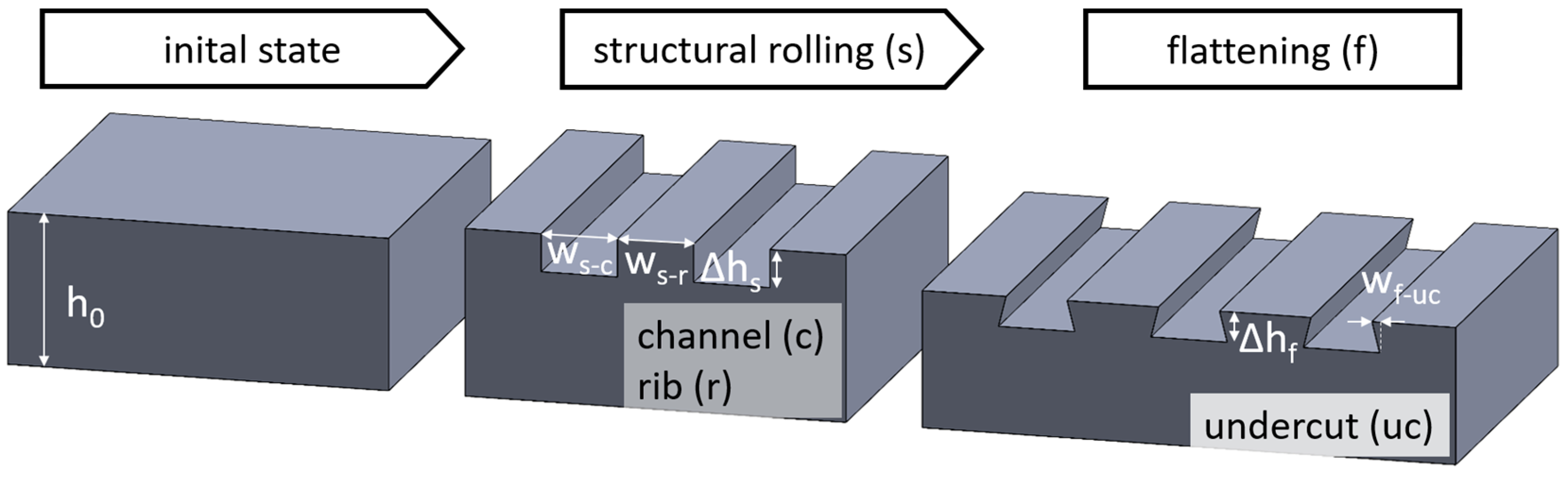
To overcome this, a surface structure with undercuts was needed, allowing the aluminum melt to clamp over a larger area [17]. Surface structures can be created using ablative processes, such as micro-milling and laser surface texturing [18,19]. Joining methods, like coining or imprinting, can reduce process times and manufacturing costs but are limited in workpiece size as well [20]. Therefore, a continuous multi-pass rolling process was developed by Senge et al. [21] at the Institute of Metal Forming (IBF), which allows for the creation of channel-like surface structures with undercuts (Figure 1).
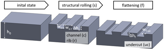
Figure 1.
Process scheme for channel-like surface structures with undercuts.
In the first pass, rollers with a machined surface structure were used to imprint grooves into the surface of a steel sheet. The resulting rectangular ribs were then flattened in a second pass (flat rolling). The tips of the ribs spread horizontally and form an undercut of up to a 50 µm width [22].
The created structures were inserted into an HPDC process at the Foundry Institute (GI) of RWTH Aachen. The strength of the joint depends on the geometry of the structure, especially the width of the undercut [22]. Conducted shear tests showed that the connection was loadable up to 45 MPa. Further studies also investigated the formation of the undercut, observing the formation of an inner fold that might weaken the connection [23]. To further investigate the different joining methods in hybrid casting, an industry-related example part for the high-pressure die casting process was developed by the Foundry Institute (GI) of RWTH Aachen [16]. This part enables the use of a structured and bent steel sheet insert. In combination with the X-shaped aluminum casting, a complex compound geometry is possible. In addition, the proposed process chain of structural rolling and die casting is suitable for mass production.
It is generally known that the mechanical properties as well as the flowability of AlSi alloys in high-pressure die casting can be influenced not only via the geometry of the casting but also via the process parameters. Lower pouring temperatures as well as a higher proportion of oxides in the melt can significantly reduce flowability and, thus, mold filling capacity [24,25]. Furthermore, the risk of casting defects, such as cold flow and porosity, and their distribution are affected via the melt velocity during mold filling and the thermal boundary conditions in the shot sleeve after the melt dosing process [26,27].
3. Methods and Processes
The first step in this work was to demonstrate the improvement in the strength of the example parts due to the surface structure. To obtain a comparison between unstructured and structured parts, a fatigue test with dynamic loading was designed for the entire part. The hypothesis was that the surface structure would increase the load bearing capacity and that wider structures would proportionally increase the compound’s strength. In the next step, the goal was to determine the influences of varied process parameters in HPDC as well as common upstream and downstream treatment processes on the compound strength. In order to represent a wide range of casting conditions common to the industry, their effect was evaluated via means of an extreme value analysis. During casting, the relatively small channels must be filled with melt. The hypothesis is that the melt and mold temperature, as well as the melt velocity during the filling phase, affect the resulting strength. In addition, the effects of fluctuations in the dosing process and, thus, deviations of the changeover point between the prefilling phase and the mold filling phase were investigated. Regarding the upstream and downstream process parameters, the influence of preheating the insert to be encased in the casting process, water bath quenching of the hybrid part after casting and solution annealing in the form of a T6 heat treatment were investigated. To evaluate the effects on the performance of the hybrid parts, the tensile strength of the joint was measured on specimens of the example part.
3.1. Production of Steel Sheet Inserts for HPDC
The sheet insert was made of 2.0 mm thick DC04 steel to meet the strength and ductility requirements for the base material. Sheets of a 160 mm width and a 475 mm length were used for structural rolling. Rolling was conducted on a roll forming machine (P3.160; Dreistern GmbH & Co. KG (Schopfheim, Germany). Since the cast metal is applied on both sides, the channel structures were imprinted longitudinally in the central area on both sheet surfaces (Figure 2).

Figure 2.
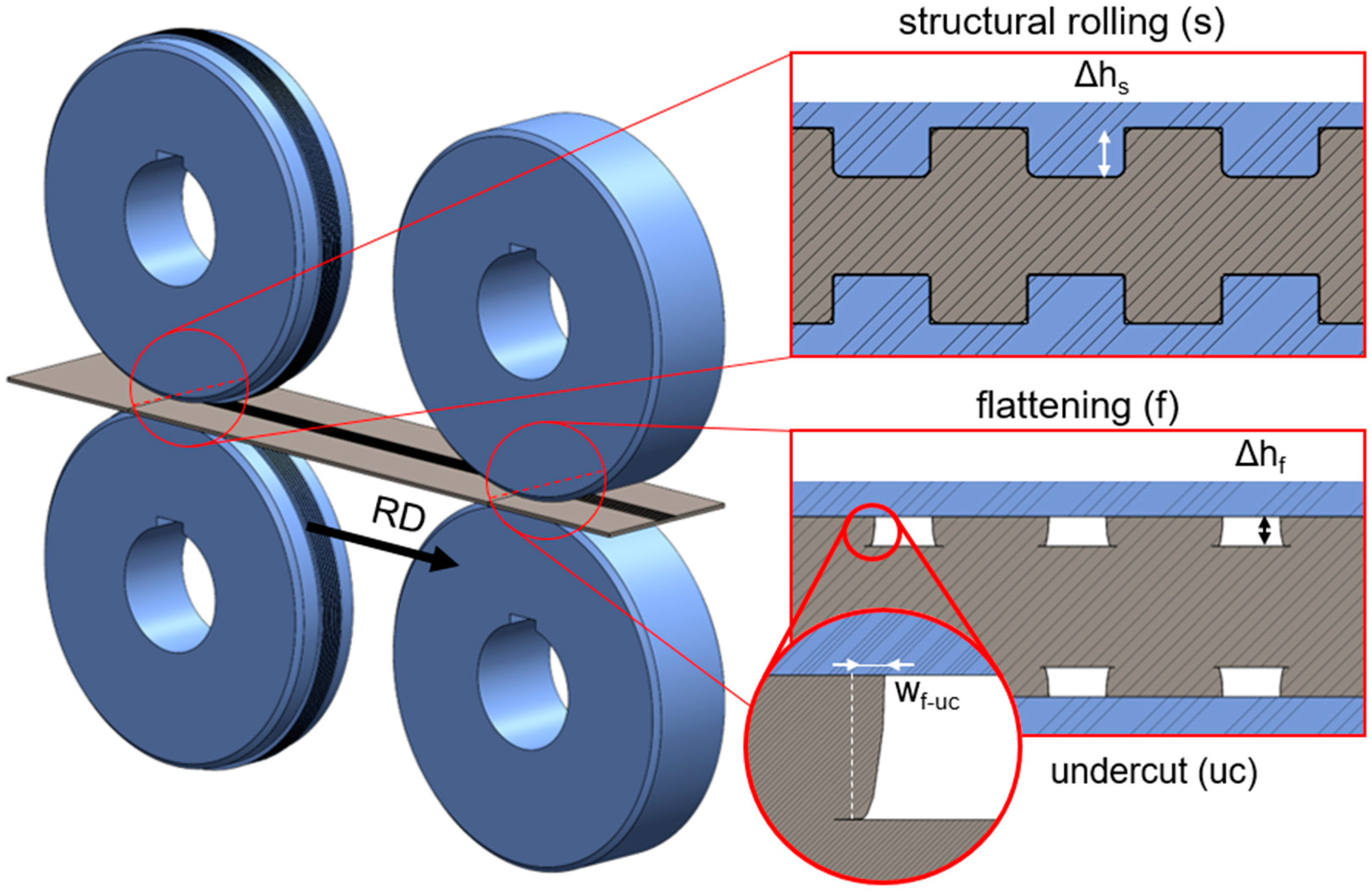
Process scheme of double-sided structural rolling and flattening.
For the first pass, two profiled rollers with 92.5 mm radius and 13 mm structure width were used. The roll profile had seven ribs and six channels, each with a width of 1.0 mm and a depth of 0.5 mm, and radii at the rib edges of 0.05 mm (bottom) and 0.10 mm (top). Optionally, an intermediate structuring step was performed to create wider structures of 25 mm width. The optional rollers additionally imprinted three ribs and channels on each side of the existing structure. The roll profile had the same rib and channel geometry as the first pass. Two rollers with a radius of 93.0 mm were used for the flattening pass at a rolling speed of 5.8 m/min. In the first pass, channels of an approx. 479 µm depth (Δhs) were imprinted into the sheet surface. The resulting ribs were flattened, resulting in an average channel depth of Δhf = 333 µm and an average undercut width of wf-uc = 58 µm. The geometry measurement was conducted on cross-sectional specimens using a Keyence VHX-7000 (Osaka, Japan) digital microscope.
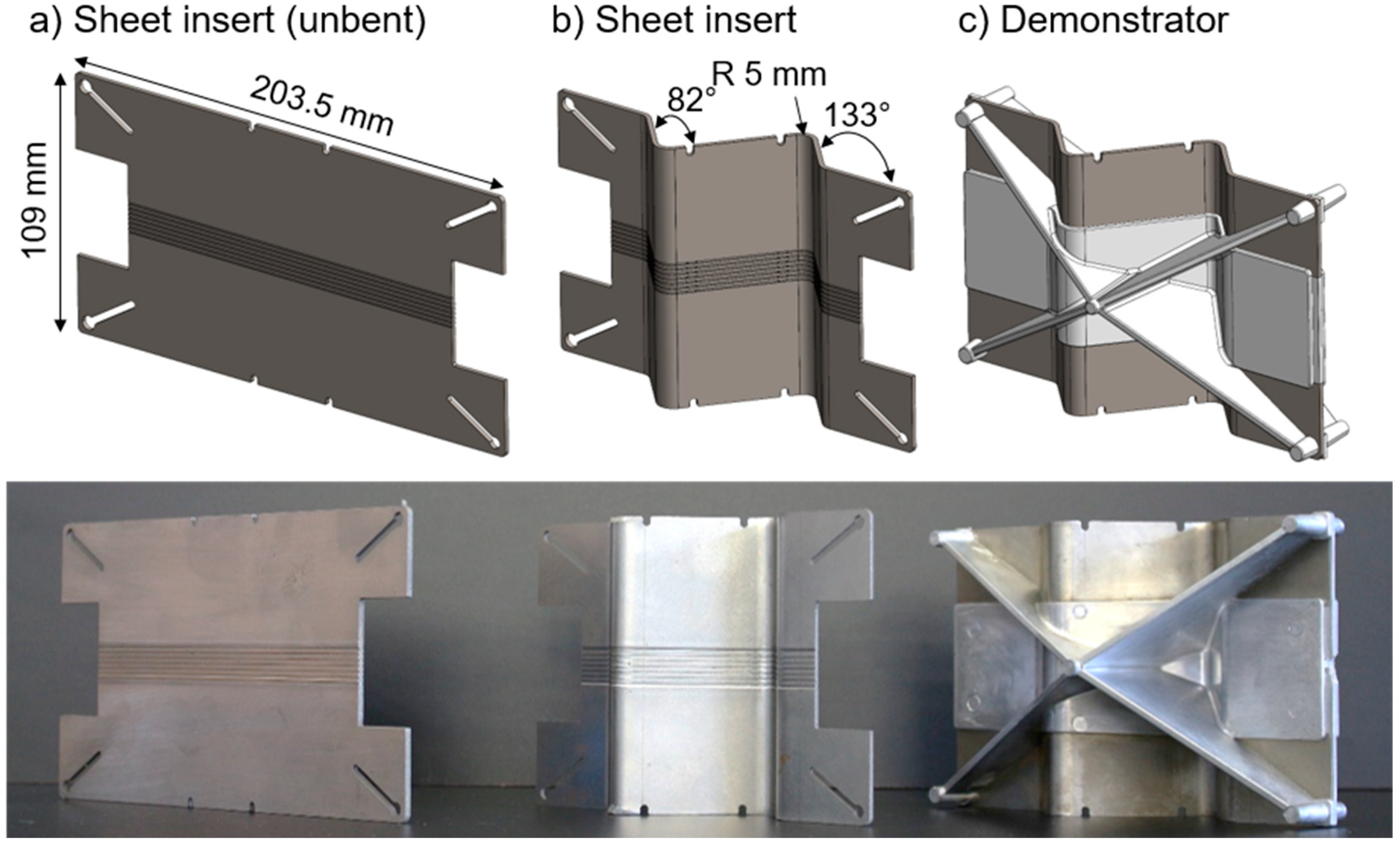
After structuring, the plates were roller levelled and two sheet inserts of 109 mm × 203.5 mm were cut from each plate with a waterjet (Figure 3a). The cut specimens were die-bent on a press brake (Trumpf TrumaBend V50; Ditzingen, Germany) into their final shape (Figure 3b). The final geometry required four bending operations, with bending angles of 82° and 133°, twice each. A punch with a radius of 5.0 mm and a die with an opening of 16 mm were used. After bending, the edges at the bending were deburred at the bending curve.

Figure 3.
Figure of the cut insert geometry (a), bent insert (b) and hybrid casting (c).
3.2. High-Pressure Die Casting of the Hybrid Part
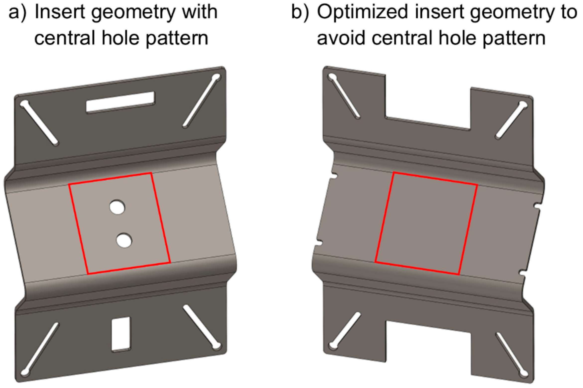
The hybrid casting trials were performed in a modified version of the high-pressure die casting tool used by Joop [16], which represents structural castings from automotive applications with complex geometric conditions, such as a roof cross-member profile. In order to provide optimal conditions for a hybrid of cast aluminum and steel sheet, the existing hole geometry was optimized using casting simulation software (Magmasoft 5.4) to achieve a more uniform filling of the die and, thus, reduce the risk of casting defects (Figure 4). Furthermore, the design of a region without a central hole pattern for the melt flow in the sheet metal insert was achieved. This significantly reduced the interference of side effects, such as melt penetrating through the insert. In addition, this central region represents an area where the compound strength can be related solely to the surface structure.
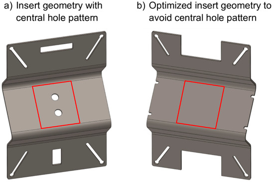
Figure 4.
Comparison between original insert version (a) [16] and optimized version for the production of compound test specimens (b).
The stiffening structures were cast from an AlSi10MnMg primary alloy, which has high specific strength but low ductility without heat treatment. The chemical composition is given in Table 1.

Table 1.
Chemical composition of the AlSi10MnMg.
The tests were carried out on a vacuum-assisted Bühler H630-SC (Uzwil, Switzerland) cold-chamber high-pressure die casting machine with a nominal locking force of 6900 kN. The aluminum alloy was degassed to a density index smaller than 1.0 to minimize hydrogen content. Oil was used as thermoregulation fluid for both the shot sleeve and the die. The boundary conditions for the casting trials are shown in Table 2.
Table 2.
Boundary conditions for the conducted casting trials.
The Design of Experiment (DoE) carried out is shown in Table 3. To minimize the risk of interactions between configurations within the DoE, the set of five start-up parts was used to provide near-steady-state boundary conditions for the process setup.
Table 3.
Design of Experiments to analyze the influences of the HPDC process parameters and up-/downstream processes.
In the first five configurations, the process parameters of HPDC are varied to analyze the influence of melt and cavity temperature (ID 2), melt velocity at the gate (ID 3, 4) and the changeover point from pre-fill to cavity-fill (ID 5, 6). The remaining three configurations are used to determine how common upstream and downstream processes in HPDC affect the part. As an upstream process, the sheet insert was preheated to a temperature of 400 °C prior to die casting (ID 7), while as a downstream process, water quenching (ID 8) and a T6 heat treatment (ID 9) was performed. For the T6 heat treatment, the demonstrator parts were solution annealed at 520 °C for 1 h and artificially aged at 160 °C for 6 h.
3.3. Casting of the Hybrid Component and Preparation of the Tensile Testing Sample
For each process variation of the following tests, a set of seven parts was taken from the batch of castings. These seven parts were prepared and tested. To quantify the static bond strength, a sample is taken from the casting for tensile testing. To eliminate influencing factors from the overall complex geometric conditions, the sample section is cut from the center of the casting as shown in Figure 5. A horizontal bandsaw with controlled hydraulic feed was used to apply minimal force. The length of the structure varied in the range of 50 ± 3 mm due to the semi-automatic sawing process. Each specimen was individually measured to compensate for any effects on the compound’s strength. Centrally located holes were then milled in the aluminum casting to allow application of the test force normal to the bond surface (Figure 6). For dynamic testing, the castings were separated only from the gating system and the overflows. No other mechanical process was performed prior to testing. The length of the structure within the demonstrator part is approximately 153.5 mm.
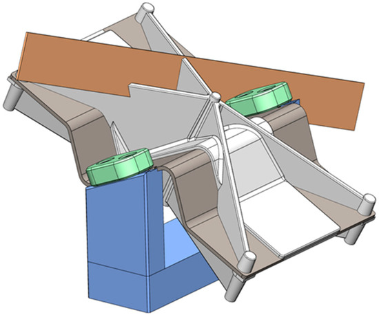
Figure 5.
Tensile test specimen cut via horizontal band saw.

Figure 6.
Milling holes in the tensile sample for the test fixture.
3.4. Static and Dynamic Testing of the Demonstrator Part
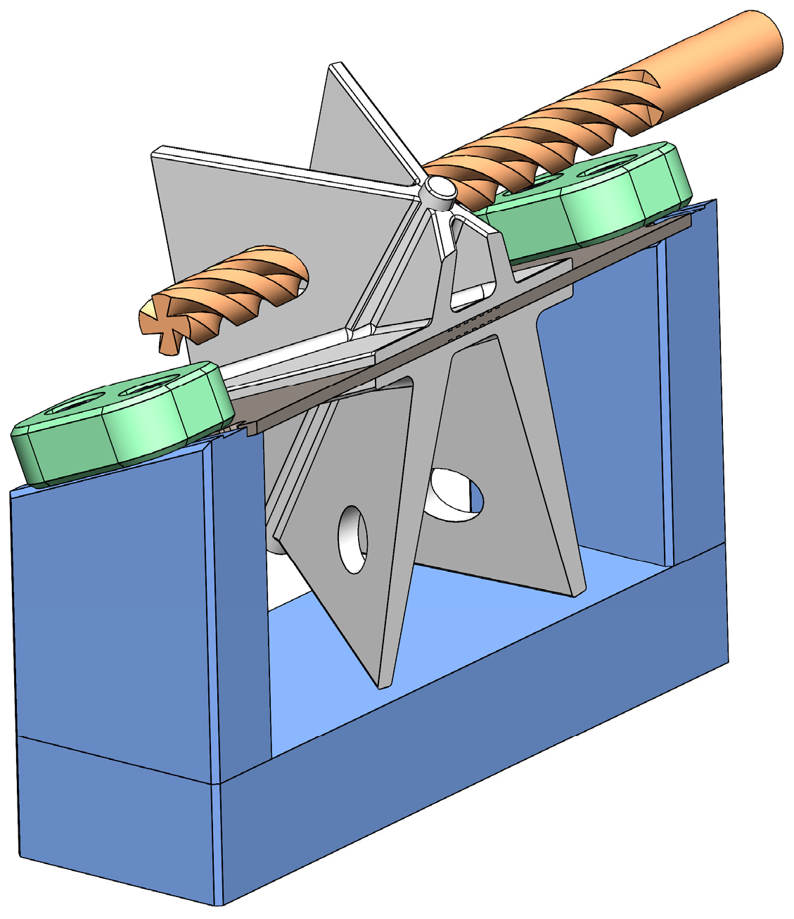
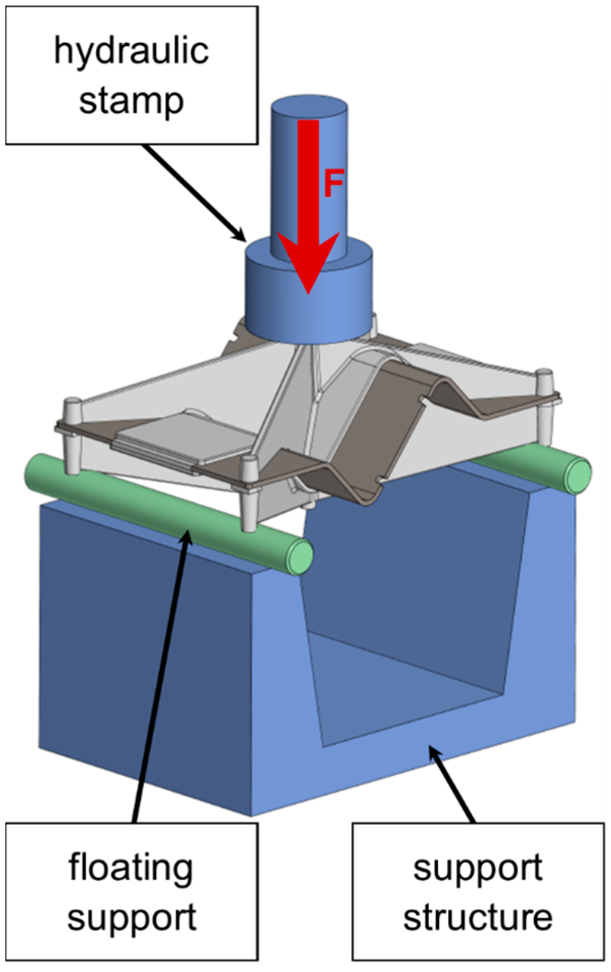
Dynamic testing was performed on a 250 kN Schenk (Darmstadt, Germany) servo-hydraulic machine. Demonstrator parts without (reference) and with 13 mm and 25 mm wide surface structures were tested, all cast according to ID 1 (Table 2). In the case of the unstructured part, the materials were bonded only through the holes in the sheet steel insert. The demonstrator part was placed in a three-point bending test fixture, as shown in Figure 7. The specimen was tested at a stress ratio of 0.1 with a loading force alternating between 3 kN and 30 kN at a frequency of 20 Hz until failure. Crack initiation was detected via an increase in displacement.
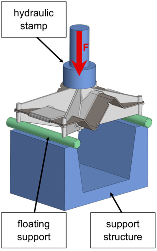
Figure 7.
Demonstrator part in dynamic test.
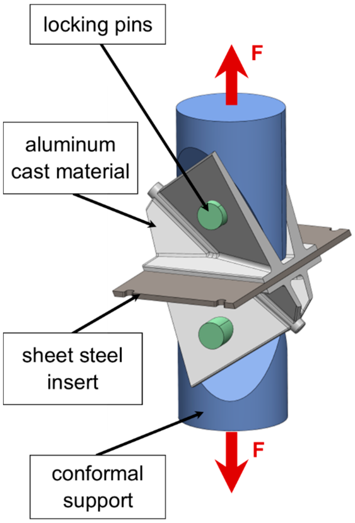
For static testing, the specimen was installed in a Zwick Z100 (Ulm, Germany) tensile tester, with custom-made specimen grips and loaded to failure (Figure 8). Prior to testing, the sample was preloaded with 10 N. A travel speed of 0.5 mm/min was used for the tensile test. In this test setup, only parts with structured surfaces could be tested.

Figure 8.
Cut demonstrator part in tensile test.
4. Results and Discussion
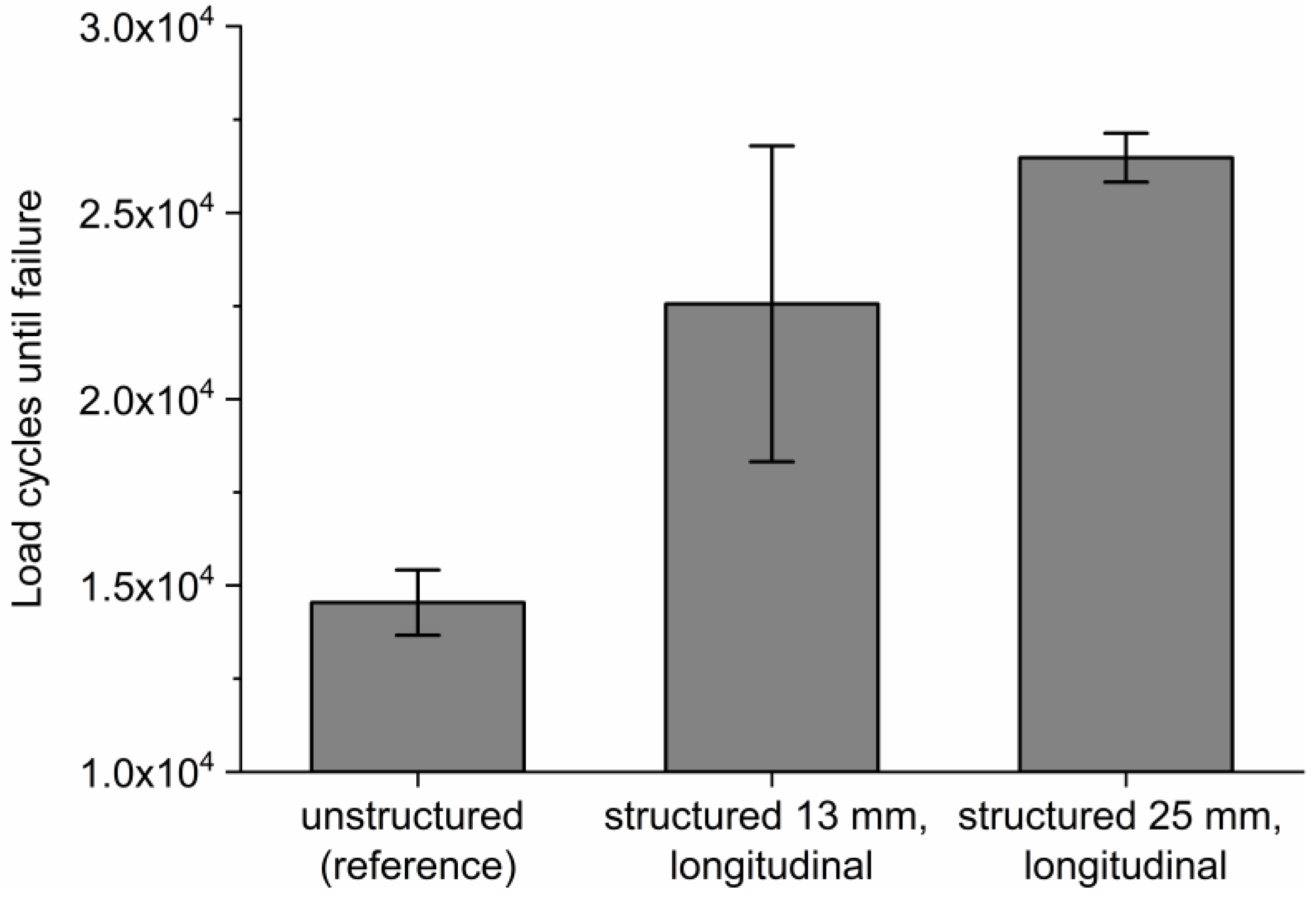
For each group of dynamic and static tests evaluated, the standard deviation of the measurement results was added as an error bar in the positive and negative directions. The influence of the surface structure on the strength of the part can be seen from the dynamic test results in Figure 9. Failure of the parts was due to fracture of the die-cast aluminum rather than failure of the interlock. A demonstrator part joined only via the interlock through the holes in the sheet steel endured an average of ~14.500 load cycles. A 13 mm wide surface structure increased the load bearing capacity by around 55%. With the 25 mm wide surface structure, approximately 17% more load cycles could be achieved. This demonstrates the significant contribution of the surface structure to the integrity of the part.

Figure 9.
Influence of surface structure on the bending cycles to failure.
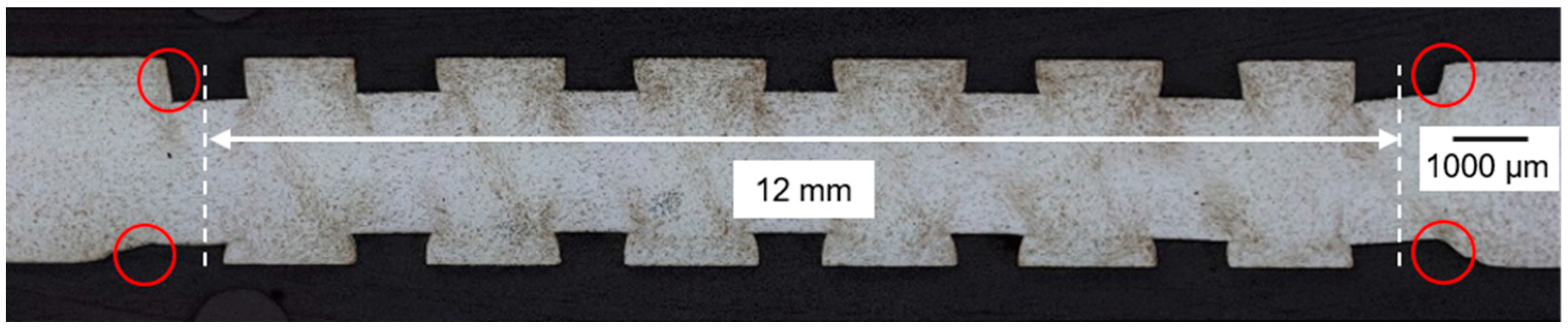
Failure of the interlock was observed during tensile testing of the cut specimens. No fracture of the base materials occurred, but the interlocking failed due to the deformation of the structure and the sliding of the interlocked surfaces against each other. For evaluation, the measured mechanical load from the tensile test is converted to an equivalent stress value, σeq. The length of the specimen after sawing and the maximum width of the insert structure used result in a rectangular interlocking area that is used for the stress calculation. Microscopic analysis (Figure 10) showed that the outermost channels of the surface structure did not form undercuts on the outside (Figure 10, circles). Therefore, half of the channel width was subtracted on each side, resulting in a nominal width of 12 mm and 24 mm.

Figure 10.
Cross-section view of 13 mm structure. Reduced undercuts for outer channels and 12 mm nominal interlock width.
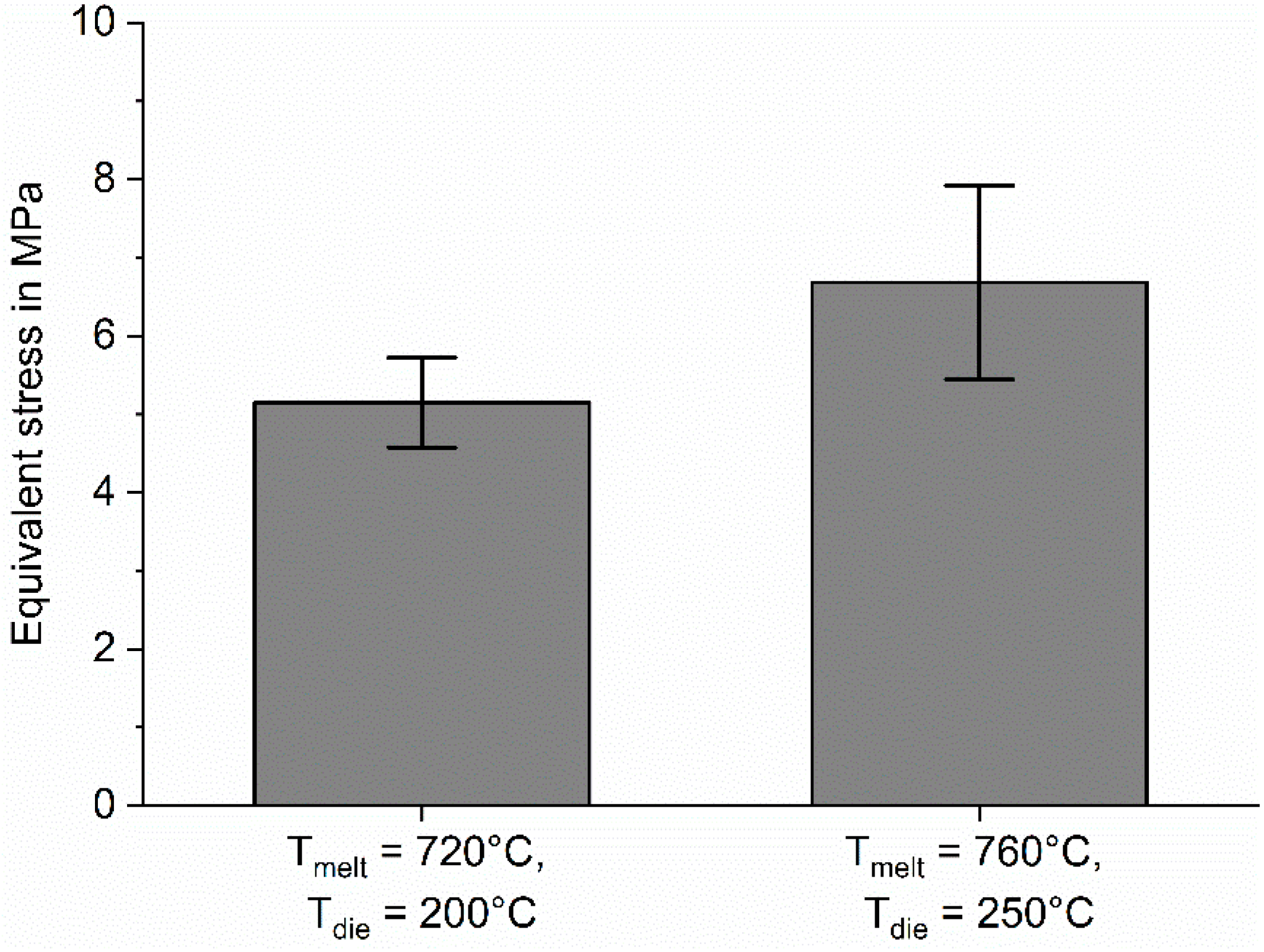
The results were then compared to the strength of the reference parameter set. The reference parameter set (Table 3, ID 1) produced a mechanical interlock with an equivalent resilience of σeq = 6.9 MPa. The results in Figure 11 show that increasing the melt and mold temperature by 40 °C and 50 °C, respectively, improved the compound strength by 30%. The observed result is in line with expectations, as it is known that the flowability of AlSi alloys used in HPDC increases with higher superheat, allowing the melt to fill the narrow channel structures more easily [28].
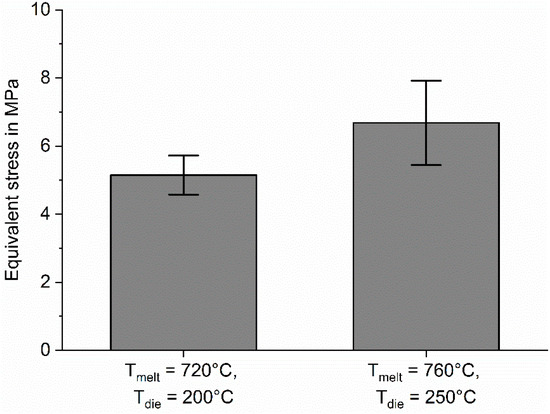
Figure 11.
Influence of melt and die temperature on the compound strength.
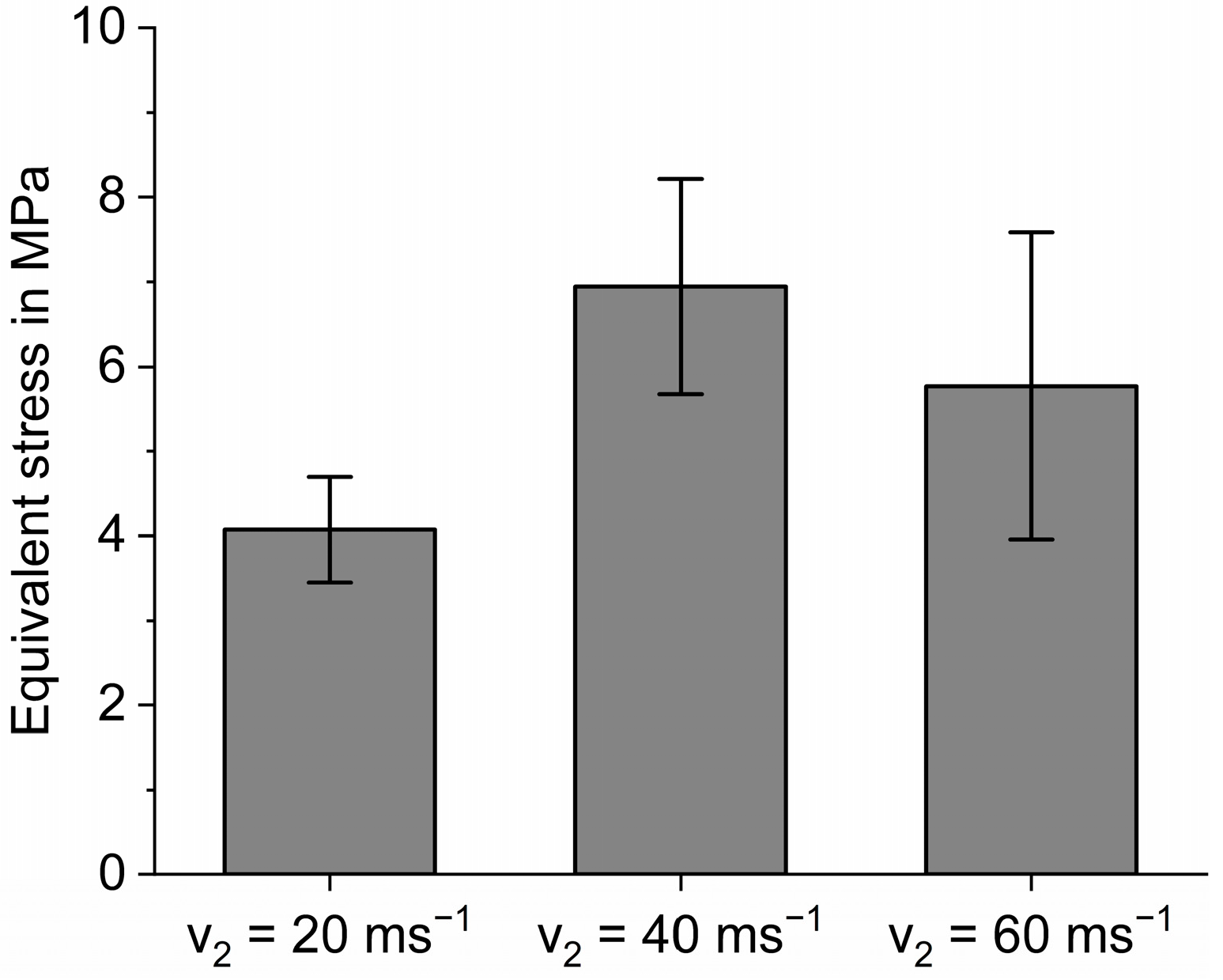
As shown in Figure 12, a reduction in melt velocity to 20 ms−1 at the gate resulted in a significantly lower strength. The reason may be that a lower velocity can cause premature solidification effects in the gate area [29].

Figure 12.
Influence of gate velocity on mechanical compound strength.
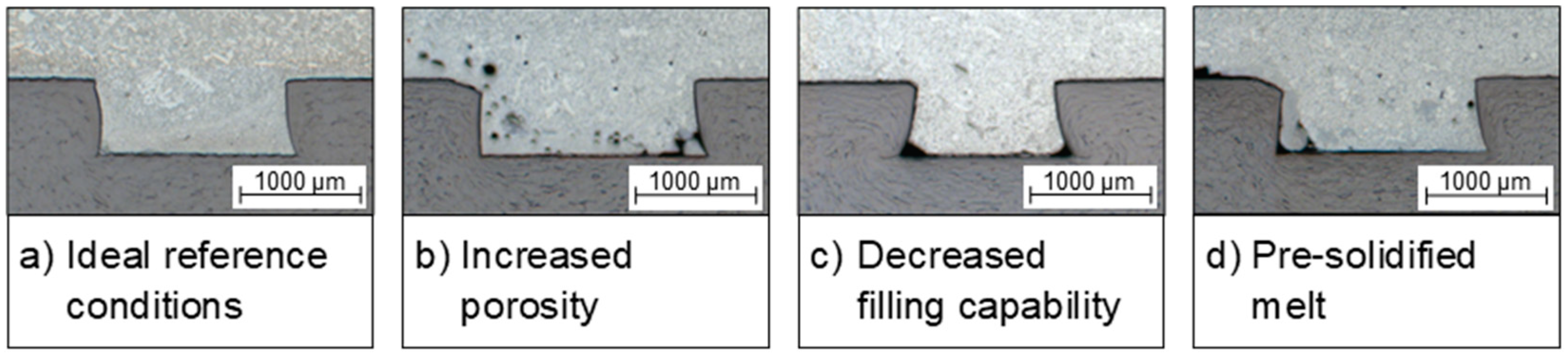
This reduces the potential for the melt to penetrate the structured surface of the insert (Figure 13c). The resulting test specimens showed a 41% reduction in resilience. A similar but smaller 17% reduction in equivalent resilience was observed at a high melt velocity of 60 ms−1 at the gate. Clearly, the chosen velocity exceeded the optimum for rapid cavity filling, which, according to Karban et al., can cause additional microporosity in the part (Figure 13b) [30].
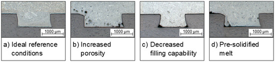
Figure 13.
Micrograph sections showing ideal undercut channel filling conditions (a), increased porosity levels in the channels (b), sections with reduced filling capacity of the melt (c) and sections with partially prefilled channels (d).
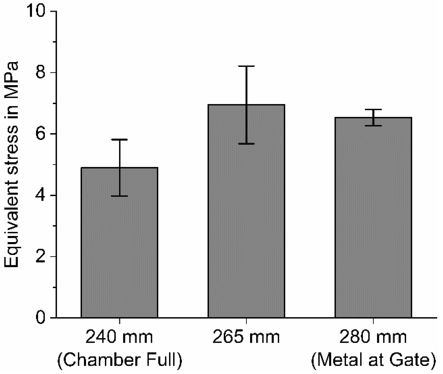
As shown in Figure 14, especially an early changeover point significantly reduced the strength of the compound by 29%. Because the amount of melt varies slightly during the dosing process, the theoretical “Chamber Full” moment also varies in reality. By accelerating the plunger earlier, residual air in the shot sleeve can be partially included in the melt flow. As a result, the risk of externally solidified crystals increases [31] and the filling quality of the structures degrades. Postponing the changeover point closer to the position of “Metal at Gate” resulted in only a minor reduction of 6%, indicating that there was no significant prefilling of the channels (Figure 13d).

Figure 14.
Influence of the changeover point on the mechanical compound strength.
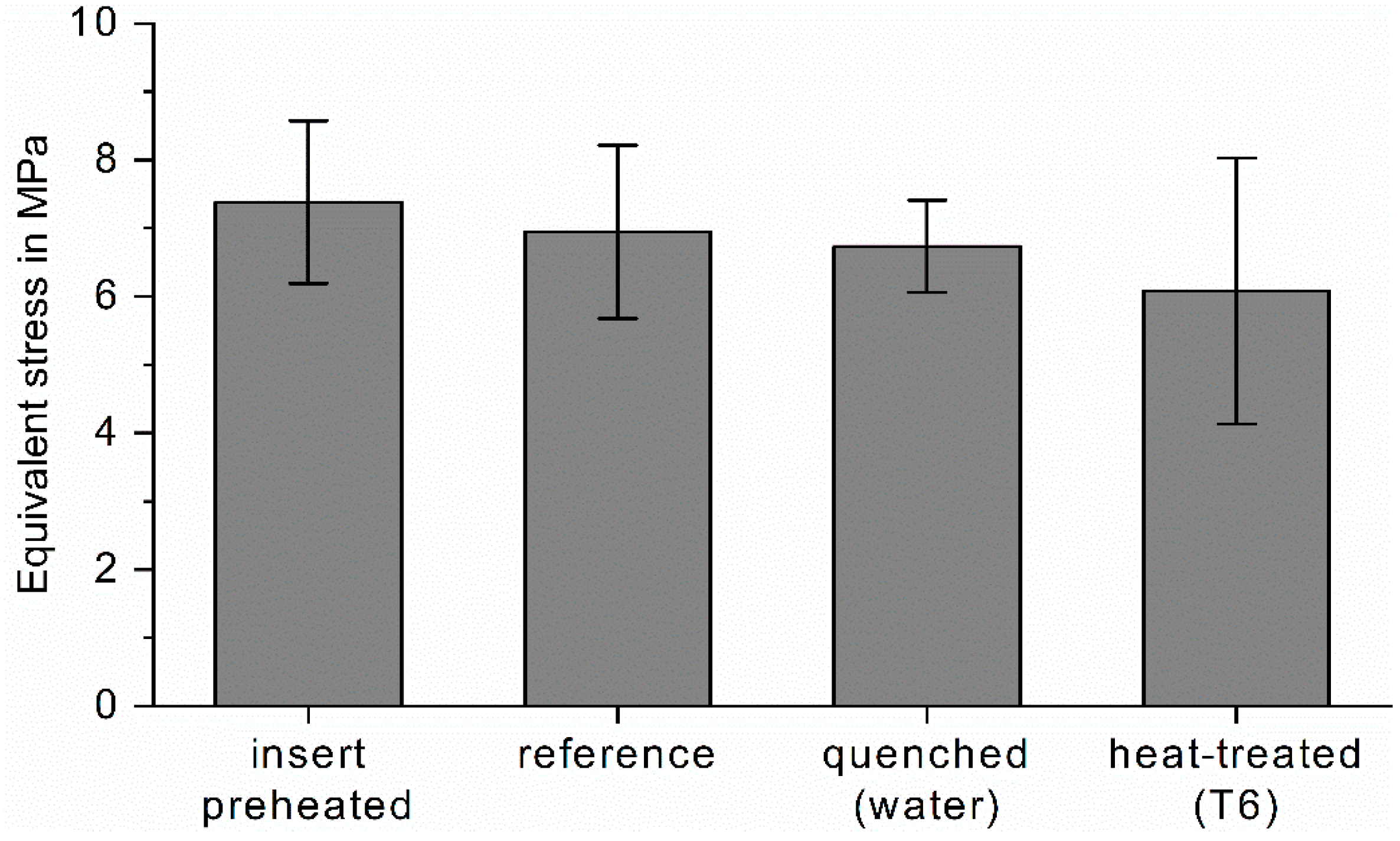
Within the error deviation, insert preheating, water quenching and a T6 heat treatment did not appear to have a significant effect or may slightly degrade the compound strength (Figure 15). The reason appears to be that, except for insert preheating, these processes do not directly affect the filling of the structures with melt. For the preheated insert, rapid cooling was observed after placement in the die, as the temperature difference was quickly equalized by the large mass of the mold. Changes in material properties due to downstream treatments have little effect on the compound strength compared to the formation of the interlock.
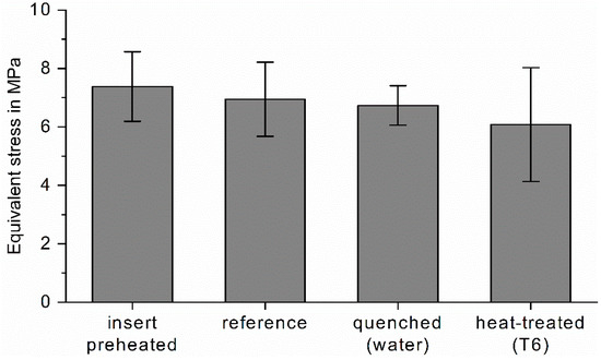
Figure 15.
Influence of up- and downstream processes on the mechanical compound strength.
5. Summary and Conclusions
The results show that the compound demonstrator with a mechanical interlock between sheet metal and cast aluminum can be produced via high-pressure die casting and that surface structures can contribute to and enhance the strength of the part. The results are summarized in Table 4.
Table 4.
Tensile test results of test samples.
The results show that deviations in the process parameters can cause various casting defects, resulting in a significant change in the bond strength. Two main effects were observed and the following conclusions were drawn from the results:
- (1)
- Complete filling of the channel structure is critical to the strength of the compound:
- ○
- Increasing the melt and die temperature reduces the risk of cold flow and increases the ability of the melt to fill the undercut channels, resulting in a higher strength during testing.
- ○
- Significantly lower gate velocities during the mold filling phase and premature changeover points result in poorer channel filling and reduced compound strength.
- ○
- Too high gate velocities also reduce the compound strength via increasing the level of porosity observed in the channels.
- (2)
- The evaluation of upstream and downstream processes such as insert preheating, post-casting water quenching and an additional T6 heat treatment did not significantly affect the test performance, thus reinforcing the main conclusion (1).
Author Contributions
Conceptualization, L.B. and A.R.; methodology, L.B. and A.R.; software, A.R.; validation, L.B. and A.R.; formal analysis, U.V. and D.B.; investigation, L.B.; resources, L.B. and A.R.; data curation, L.B. and A.R.; writing—original draft preparation, L.B.; writing—review and editing, U.V., A.B.-P., A.R. and D.B.; visualization, L.B. and A.R.; supervision, U.V., A.B.-P. and D.B.; project administration, U.V., A.B.-P. and D.B.; funding acquisition, U.V., A.B.-P. and D.B. All authors have read and agreed to the published version of the manuscript.
Funding
Funded by the Deutsche Forschungsgemeinschaft (DFG, German Research Foundation; project ID: 245566034).
Data Availability Statement
The data presented in this study are available upon request from the corresponding author.
Acknowledgments
Special thanks to Niklas Fehlemann, Manuel Henrich and Marc Grümmer for the dynamic fatigue testing at IEHK.
Conflicts of Interest
The authors declare no conflict of interest. The funders had no role in the design of the study; in the collection, analyses or interpretation of data; in the writing of the manuscript; or in the decision to publish the results.
References
- Meschut, G.; Merklein, M.; Brosius, A.; Drummer, D.; Fratini, L.; Füssel, U.; Gude, M.; Homberg, W.; Martins, P.; Bobbert, M.; et al. Review on mechanical joining by plastic deformation. J. Adv. Join. Process. 2022, 5, 100113. [Google Scholar] [CrossRef]
- Pasligh, N. Hybride Formschlüssige Strukturverbindungen in Leichtbaustrukturen aus Stahlblech und Aluminiumdruckguss. Ph.D. Thesis, Gießerei-Institut, RWTH Aachen University, Aachen, Germany, 2011; p. 224. [Google Scholar]
- Mori, K.; Bay, N.; Fratini, L.; Micari, F.; Tekkaya, A.E. Joining by plastic deformation. CIRP Ann. Manuf. Technol. 2013, 62, 673–694. [Google Scholar] [CrossRef]
- Cai, W.; Daehn, G.; Vivek, A.; Li, J.; Khan, H.; Mishra, R.S.; Komarasamy, M. A State-of-the-Art Review on Solid-State Metal Joining. J. Manuf. Sci. Eng. 2019, 141, 031012. [Google Scholar] [CrossRef]
- Mishra, R.S.; Ma, Z.Y. Friction stir welding and processing. Mater. Sci. Eng. R Rep. 2005, 50, 1–78. [Google Scholar] [CrossRef]
- Li, L.; Nagai, K.; Yin, F. Progress in cold roll bonding of metals. Sci. Technol. Adv. Mater. 2008, 9, 23001. [Google Scholar] [CrossRef]
- Milner, D.R.; Rowe, G.W. Fundamentals of Solid-Phase Welding. Metall. Rev. 1962, 7, 433–480. [Google Scholar] [CrossRef]
- Salamati, M.; Soltanpour, M.; Fazli, A.; Zajkani, A. Processing and tooling considerations in joining by forming technologies; part A—Mechanical joining. Int. J. Adv. Manuf. Technol. 2019, 101, 261–315. [Google Scholar] [CrossRef]
- Pickin, C.G.; Young, K.; Tuersley, I. Joining of lightweight sandwich sheets to aluminium using self-pierce riveting. Mater. Des. 2007, 28, 2361–2365. [Google Scholar] [CrossRef]
- He, X. Clinching for sheet materials. Sci. Technol. Adv. Mater. 2017, 18, 381–405. [Google Scholar] [CrossRef]
- Mori, K.; Abe, Y. A review on mechanical joining of aluminium and high strength steel sheets by plastic deformation. Int. J. Lightweight Mater. Manuf. 2018, 1, 1–11. [Google Scholar] [CrossRef]
- Bührig-Polaczek, A.; Röth, T.; Baumeister, E.; Nowack, N.; Süßmann, T. Hybride Leichtbaustrukturen in Stahlblech-Leichtmetall Verbundguss; FH Aachen: Aachen, Germany, 2006. [Google Scholar] [CrossRef]
- Noguchi, T.; Asano, K.; Hiratsuka, S.; Miyahara, H. Trends of composite casting technology and joining technology for castings in Japan. Int. J. Cast Met. Res. 2008, 21, 219–225. [Google Scholar] [CrossRef]
- Fang, X.; Gundlach, J.; Schipperges, J.-J.; Jiang, X. On the Steel–Aluminum Hybrid Casting by Sand Casting. J. Mater. Eng. Perform. 2018, 27, 6415–6425. [Google Scholar] [CrossRef]
- Ucsnik, S.; Gradinger, R.; Becirovic, A.; Waldhör, A. Enhanced Performance of Steel-Aluminium Cast Nodes through Cold Metal Transfer. Mater. Sci. Forum 2013, 765, 736–740. [Google Scholar] [CrossRef]
- Joop, D. Präzisionsbestimmende Faktoren bei der Herstellung blechverstärkter Hybridstrukturen im Druckguss: Grenzflächenanalyse und Verzugsoptimierung. Ph.D. Thesis, Gießerei-Institut, RWTH Aachen University, Aachen, Germany, 2018. [Google Scholar]
- Senge, S.; Hirt, G. Evaluation of Modular Roll-Setup to Roll Grooves into Steel Sheets. Appl. Mech. Mater. 2015, 794, 120–127. [Google Scholar] [CrossRef]
- Aurich, J.C.; Reichenbach, I.G.; Schüler, G.M. Manufacture and application of ultra-small micro end mills. CIRP Ann. Manuf. Technol. 2012, 61, 83–86. [Google Scholar] [CrossRef]
- Elsner, C.; Zajadacz, J.; Zimmer, K. Replication of 3D-microstructures with undercuts by UV-moulding. Microelectron. Eng. 2011, 88, 60–63. [Google Scholar] [CrossRef]
- Grützmacher, P.G.; Rosenkranz, A.; Atalay, E.; Szurdak, A.; Gachot, C.; Hirt, G.; Mücklich, F. Guiding lubricant on stainless steel surfaces by channel-like structures fabricated by roller- and micro-coining. Physica A Stat. Mech. Its Appl. 2018, 505, 482–489. [Google Scholar] [CrossRef]
- Senge, S.; Brachmann, J.; Hirt, G.; Bührig-Polaczek, A. Interlocking Multi-Material Components made of Structured Steel Sheets and High-Pressure Die Cast Aluminium, in: ESAFORM. In Proceedings of the 20th International ESAFORM Conference on Material Forming, Dublin, Ireland, 26–28 April 2017; p. 190007. [Google Scholar]
- Senge, S.; Brachmann, J.; Hirt, G.; Bührig-Polaczek, A. Evaluation of interlocking bond strength between structured 1.0338 steel sheets and high pressure die cast AlMg5Si2. In Proceedings of the 21st International ESAFORM Conference on Material Forming, Palermo, Italy, 23–25 April 2018; p. 40019. [Google Scholar]
- Ringel, A.; Lohmar, J. Optimization of the Surface Geometry in Structured Cold Rolling for Interlocking of Formed and Die-Cast Metal Components. Defect Diffus. Forum 2022, 414, 89–94. [Google Scholar] [CrossRef]
- Timelli, G.; Bonollo, F. Fluidity of aluminium die castings alloy. Int. J. Cast Met. Res. 2007, 20, 304–311. [Google Scholar] [CrossRef]
- Han, Q.; Zhang, J. Fluidity of Alloys Under High-Pressure Die Casting Conditions: Flow-Choking Mechanisms. Metall. Mater. Trans. B 2020, 51, 1795–1804. [Google Scholar] [CrossRef]
- Ma, Y.-H.; Yu, W.-B.; Zhou, Y.-Q.; Xiong, S.-M. Influence of different high pressure die casting processes on 3D porosity distribution of Mg-3.0Nd-0.3Zn-0.6Zr alloy. China Foundry 2021, 18, 521–528. [Google Scholar] [CrossRef]
- Sui, D.; Han, Q. Effects of Different Parameters on Porosity Defects Between the Horizontal and Vertical Shot Sleeve Processes. Int. J. Met. 2018, 13, 417–425. [Google Scholar] [CrossRef]
- Kim, Y.-C.; Choi, S.-W.; Cho, J.-I.; Kim, C.-W.; Kang, C.-S.; Hong, S.-K. Influence of Silicon, Superheat and Injection Speed on the Fluidity of HPDC Al-Si Alloys. In Proceedings of the 12th International Conference on Aluminium Alloys, Yokohama, Japan, 5–9 September 2010; pp. 1780–1785. [Google Scholar]
- Davis, A.J.; Robinson, P.M. Production of Aluminum Die Castings Using a Fan Gate, Part 2: The Effect of Flow Conditions at the Gate on Casting Quality. Trans. Soc. Diecasting Eng. 1975, Part 2. [Google Scholar]
- Karban, R. The Effects of Intensification Pressure, Gate Velocity, and Intermediate Shot Velocity on the Internal Quality of Aluminum Die Castings. Ph.D. Thesis, Purdue University, West Lafayette, IN, USA, 2000. [Google Scholar]
- Dou, K.; Zhang, Y.; Lordan, E.; Jacot, A.; Fan, Z. Understanding the Initial Solidification Behavior for Al–Si Alloy in Cold Chamber High-Pressure Die Casting (CC-HPDC) Process Combining Experimental and Modeling Approach. Metall. Mater. Trans. A 2022, 53, 3110–3124. [Google Scholar] [CrossRef]

Disclaimer/Publisher’s Note: The statements, opinions and data contained in all publications are solely those of the individual author(s) and contributor(s) and not of MDPI and/or the editor(s). MDPI and/or the editor(s) disclaim responsibility for any injury to people or property resulting from any ideas, methods, instructions or products referred to in the content. |
© 2023 by the authors. Licensee MDPI, Basel, Switzerland. This article is an open access article distributed under the terms and conditions of the Creative Commons Attribution (CC BY) license (https://creativecommons.org/licenses/by/4.0/).