Article

Experiment and Numerical Study on the Dynamic Response of Foam Sandwich Panels under the Near-Field Blast Loading

1
School of Mechanical Engineering, Northwestern Polytechnical University, Xi’an 710072, China
2
Xi’an Institute of Electromechanical Information Technology, Xi’an 710065, China
3
School of Mechano-Electronic Engineering, Xidian University, Xi’an 710071, China
4
Shaanxi Key Laboratory of Space Extreme Detection, Xi’an 710071, China
*
Authors to whom correspondence should be addressed.
Metals 2023, 13(10), 1745; https://doi.org/10.3390/met13101745
Submission received: 5 August 2023 / Revised: 2 September 2023 / Accepted: 15 September 2023 / Published: 14 October 2023

Abstract

:
Aiming at the problem that the blast load, generated by the explosion of the tandem-shaped-charge warhead, may cause damage to the warhead structure, material failure and even phase change, the material damage and structural protective capacity of the near-field blast load on the sandwich structure with foam-aluminum core were investigated by experimental test and numerical simulation. Firstly, the near-field blast test was performed to observe the deformation of sandwich structure and to collect the acceleration signals of fuze. Then, the mechanical properties of foam materials were tested, and a numerical model of blast load environment was established in the explicit dynamics software ANSYS/LS–DYNA 2020 R2. Finally, the experimental test data and simulation results were compared and analyzed. The strong agreement between the experiment and the simulation results indicates that the calculation method and simulation model are reasonable. Furthermore, the damage mode of foam-aluminum core materials with different densities and cell diameters under near-field blast load were carefully analyzed by simulation method. The simulation results show that, with the decrease of the density of foam-aluminum material and the increase of the cell chamber diameter, the deformation of the foam-aluminum panel gradually increases; the acceleration peak value of the fuze gradually decreases, and the pulse width barely changes and remains basically constant; the start and end times of the peak stress of the fuze cover gradually lag behind, and the peak stress hold-up time increases gradually; the maximum displacement deformation of the fuze cover decreases firstly and then increases. This work is expected to provide basic data and design guidelines for the graded foam sandwich panels of the blasting warhead fuze against the near-field blast load.

1. Introduction

As one of the types of warheads, the shaped-charge and armor-breaking warhead has been used in anti-armor operations because of its excellent armor-breaking performance since the American scientist Monroe discovered the shaped-charge effect of explosives in 1888 [1]. Therefore, it has attracted wide attention from scientists all over the world. Through test, numerical simulation or a combination of test and numerical simulation, the charge structure of the shaped-charge and armor-breaking warhead [2,3,4,5], shaped-charge liner structure [6,7,8,9,10] and standoff [11] are discussed, and the shaped-charge warhead is studied. With the emergence of reactive armor, the armor breaking performance of the shaped-charge armor-breaking warhead has been affected [12,13]. To effectively damage the main armor of the armored vehicle, the first step is to destroy the reactive armor hanging outside the armored vehicle. Therefore, the tandem-shaped-charge armor-breaking warhead has been designed [14,15,16]. The former shaped-charge armor-breaking warhead is used to destroy the reactive armor. After the reactive armor is destroyed, the latter-stage warhead will fuze, the after-stage shaped-charge warhead is detonated and the shaped-charge jet is generated to destroy the main armor. With the continuous enhancement of the defense capability of the attacked target, the tandem warhead appears in different combination forms [17], for example, the high-explosive anti-tank warhead, high-explosive anti-tank armor-piercing warhead, and so on, which are respectively used to attack different targets. In terms of the flameproof ability of the front- and rear-stage warheads, the literature [18,19,20,21,22] has studied the flameproof materials, flameproof structures and the attitude of the rear-stage warheads. For a certain type of shaped-charge and explosive compound damage warhead fuze, the shock wave, jet, fragment and other products, produced by the shaped-charge warhead explosion, will directly act on the warhead fuze, which will produce transient strong blast load, high overload, erosion and other adverse environments on the fuze, which may cause damage to the fuze structure, material failure and even material phase change, resulting in the failure of the warhead fuze to function normally. Sandwich structure is widely used in the field of explosion and blast protection due to its characteristics of lightweight, high strength, good energy absorption, vibration reduction and sound insulation. Sandwich structure is generally composed of two layers of the high-strength thin panels and light thick core layer, with relatively weak bearing capacity in the middle through welding or bonding [23]. As one important part of sandwich structure, the core is adopted using lightweight energy-absorbing materials, such as foams [24,25], honeycombs [26,27] and lattices [28], etc.
In another article by authors [29], they studied the laboratory mechanistic experimental test and numerical simulation analysis of foam-nickel sandwich structure on the blast protection of 50 g RDX-8701 explosions. In the test, by comparing the parameters such as stress and deformation of the top panel, bottom panel and core material, it was found that the blast protection effect of foam-nickel sandwich structure was significantly better than the foam-aluminum structure, as shown in Figure 1. The reason is that the deformation of foam-nickel core material was greater than that of the foam-aluminum core material under blast loading of laboratory mechanistic experimental test, which absorbs more explosive energy.
However, the preferred foam-nickel sandwich structure was fatally damaged in the 1:1 warhead field test with the 10 kg charge of RDX-8701, resulting in structural fracture of the warhead fuze. In contrast, the foam-aluminum sandwich structure had great deformation as well, but the structure of the warhead fuze remained as a whole part, indicating no failure, as shown in the following content of this paper for details. The reason is that, for the large equivalent charge explosive, the sandwich was compacted under the blast loading, resulting in the loss of capacity for energy absorption through deformation and shock wave attenuation through the pores. Consequently, this paper mainly studies the experimental test and numerical simulation analysis of foam-aluminum sandwich structure for blast protection under the blast loading of a 1:1 warhead field test.
Therefore, the above studies indicate that the protective effect of foam-nickel sandwich structure against the blast loading is obviously better than foam-aluminum sandwich structure for the small equivalent charge test. However, the protective effect of the foam-aluminum sandwich structure is better for the large equivalent charge test. As a consequence, foam-nickel and foam-aluminum core material, as commonly used sandwich structure materials, would be chosen as the appropriate one according to the corresponding explosive equivalent range.
The purpose of this work was to study the combined effect of different core material gradients on sandwich deformation mode and dynamic response of sandwich structure under the blast load. The near-field explosion test and numerical simulation were conducted on the platform of the shaped-charge–blasting composite damage warhead. The sandwich structures were analyzed in the study, such as gradient foam-aluminum with different pore diameters and porosity cores. The typical deformation/failure modes of the top steel panel, foam-aluminum panel and bottom steel panel were calculated and analyzed in detail, respectively. This work is expected to provide the basic data and design guidelines for the graded foam panels of the blasting warhead fuze against the near-field blast load.

2. Experimental Setting

For the structure and working principle of the shaped-charge–blasting composite damage warhead, the shaped-charge warhead is placed behind, the blasting warhead is placed at the front end of the warhead, and the center body of the blasting warhead reserves the cavity formed and passed by the jet/projectile, as shown in Figure 2. The shaped-charge jet/projectile can hit the target, and the blasting warhead can delay the explosion in time to produce a blast effect and further damage the target.
To investigate the dynamic response of the sandwich panels under the near-field blast load, the near-field blast test scheme was designed, as shown in Figure 3.
In the test, the shaped-charge warhead was a real charge warhead, the blasting warhead was a sand bomb, and the fuze of the blasting warhead was a test fuze, which was used to store and record the blast overload information under the near-field explosion. After the test, the recovered fuze of the blasting warhead was used to analyze the typical damage of sandwich structure, the typical deformation of foam-aluminum core and the deformation and blast overload of the fuze. The explosive of the shaped-charge warhead was RDX-8701 with a charge of 3.8 kg; the liner material was high-conductivity oxygen-free copper (OFHC-copper); the bulkhead material was 2A12 aluminum alloy (AL), and the material thickness was 5 mm; the blasting warhead was a sand bomb with counterweight treatment, and the mass was 26.3 kg (including fuze).
The sandwich structure consisting of foam-aluminum core was designed for a blasting warhead fuze, as shown in Figure 4.
The sandwich structure consists of three layers: top panel, foam-aluminum panel, and bottom panel, where the top panel was made of 45 steel (Chinese standard) with a thickness of 2 mm, the middle core layer is a foam-aluminum panel made of spherical open-cell foam-aluminum material with a thickness of 10 mm, and the bottom panel was made of polytetrafluoroethylene (PTFE) with a thickness of 2 mm. The foam-aluminum panel used in the experiment is shown in Figure 5.
As shown in Figure 5, the cell chamber was spherical in shape, with small holes on the bulkhead connecting the spheres. They were opened in six directions to avoid throughholes, which were conducive to sound absorption and filtration. The density of foam-aluminum core material is 1.12 g/cm3, and the diameter of the spherical cell chamber is 5~6 mm.
The entire structure was placed above the upper cover of the fuze and connected with the upper cover by screws. The upper cover of the fuze was connected with the fuze shell by 12 screws distributed in the circumference. The geometric model and physical object of the detonating warhead fuze are shown in Figure 6.
To test the blast overload information under the near-field explosion, the blast overload test device based on a SIMIT-AYZ-4 (20 k) acceleration sensor was designed, with a sampling rate of 100 kHz. The range of the acceleration sensor produced by the Shanghai Institute of Microsystem and Information Technology was 50,000 g. To ensure the rigid connection between the sensor and the fuze, the sensor was secondary packaged, and the packaged 3D model and physical object of the sensor are shown in Figure 7.

3. Experimental Results

3.1. Blast Process

The frame rate of the high-speed video recorder is 5000. Figure 8 shows the explosion of the early stage of the test, mainly from 0 to 0.2 ms, and the shaped-charge warhead was fully detonated after 0.2 ms.

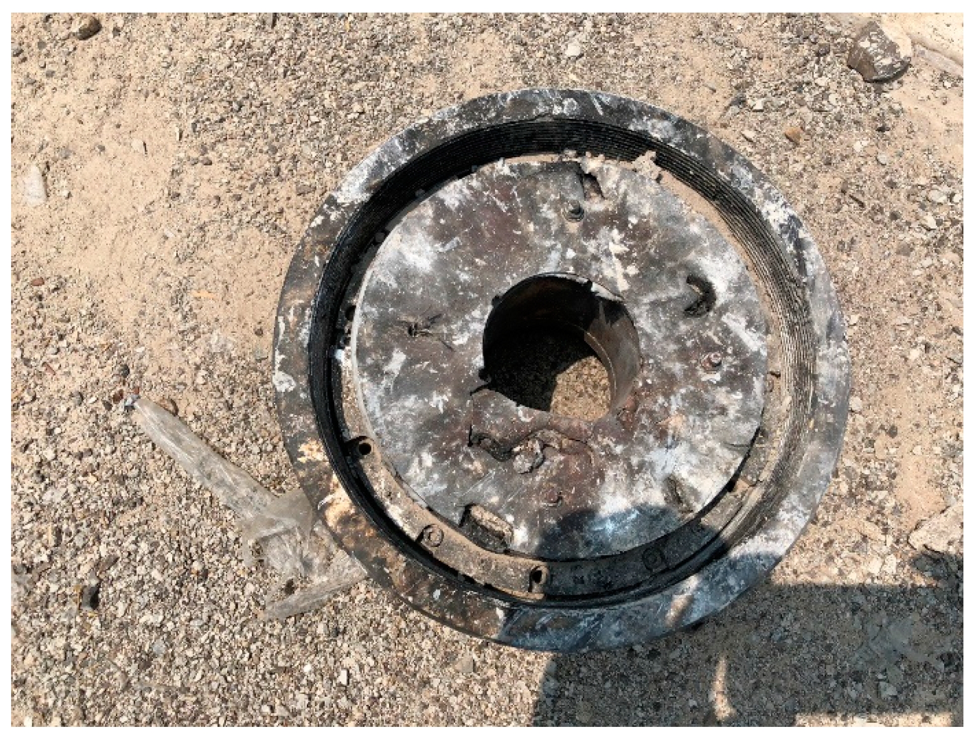
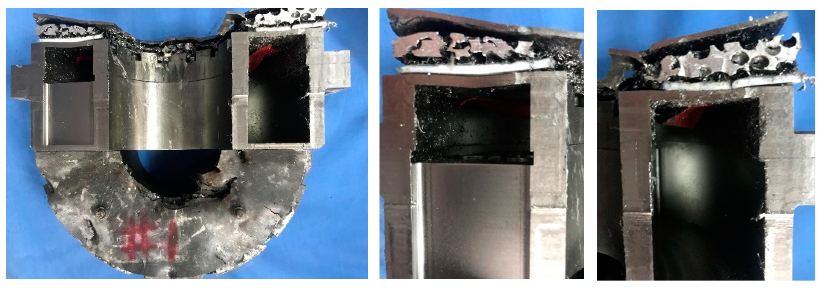
3.2. Damage and Deformation of Sandwich Protective Structure

The recovered fuze of the blasting warhead after the test is shown in Figure 9.
As shown in Figure 9, it can be seen that the overall structure of the test fuze still remains unbroken through undergoing the combined action of the blast wave, jet and fragment, while the top surface of the sandwich structure was damaged.
The fuze was section-cut by means of wire cutting to obtain the damage and deformation details of the fuze and sandwich structure, as shown in Figure 10.
Figure 11 shows the defined coordinate system to the measurement of deformation quantity. The coordinate zero point in this system was selected below the outer circle of the sandwich structure.
The position–deformation data of foam-aluminum core material after the measurement are shown in Figure 12.
The test results indicate that the sandwich structure, consisting of foam-aluminum core material, can effectively attenuate the blast impact wave. The top steel panel can be successfully used to insulate the first-order explosive products and provide structural support for the sandwich structure; meanwhile, the foam-aluminum core material is used to rapidly absorb the blast wave and provide a larger deformation space for the overall structure. The bottom panel is made of PTFE, which can attenuate the blast wave again.

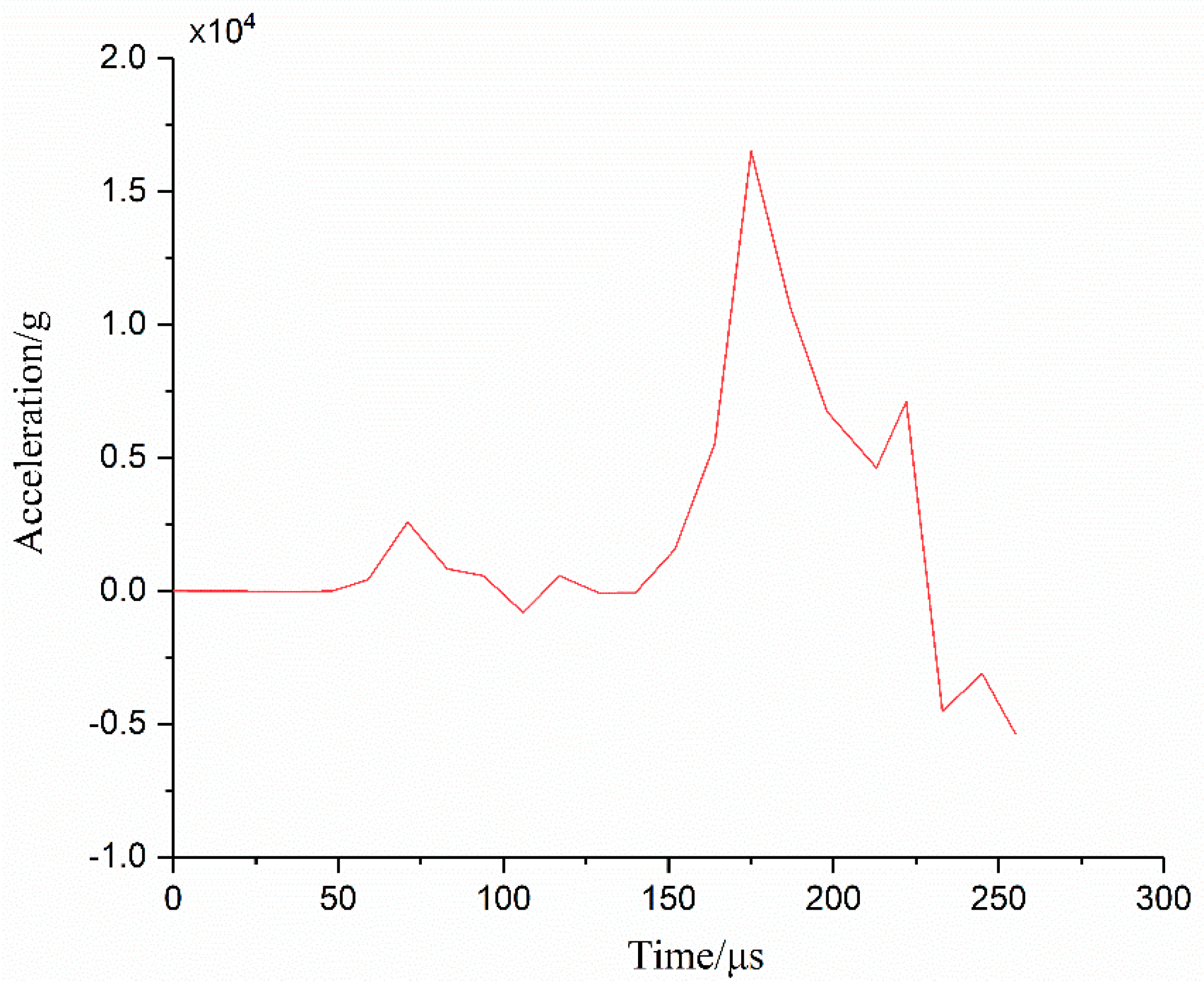
3.3. Explosion Shock Overload of Fuze

By reading the data from the tester, the acceleration–time curve of the fuze was plotted, as shown in Figure 13.
In Figure 13, the first peak value of explosion shock overload of the fuze is about 1.64 × 10⁴ g, and the pulse width is about 77 μs (time interval of 10% of peak value).

4. Test of Comprehensive Mechanical Properties of Foam-Aluminum Materials

The test piece was made of foam-aluminum core material, and its mechanical properties were tested. The size of the test piece was ϕ 30 mm × 10 mm, as shown in Figure 14.
The DDL-100 electronic universal testing machine, as shown in Figure 15, is used as the foam-aluminum material performance testing platform, with the ultimate tensile force of 100 kN.
The mechanical property test process of foam-aluminum material is shown in Figure 16.
The displacement–load curve of foam-aluminum material, obtained by quasi-static tensile mechanical property test, is shown in Figure 17, and the loading strain rate is 10−3/s.
From Figure 17, it can be seen that, initially, the foam-aluminum structure presents linear elastic deformation behavior, and the load increases evenly with the increase of displacement quantity. Then, the slope of the displacement–load curve decreases significantly, and this stage lasts for a long time, which is a key stage of energy absorption of the foam-aluminum. Finally, the foam-aluminum structure was compacted completely, and the load increases rapidly with the increase of displacement.

5. Numerical Studies

5.1. Development of the Model

The finite element model of the shaped-charge warhead was established by the explicit dynamics program ANSYS/LS–DYNA, and the Arbitrary Euler and Lagrangian (ALE) method was used for the calculation and analysis. ANSYS/LS–DYNA is a massive Multiphysics filed finite element analysis software, and it is widely applied to solve high-speed impact and explosion problems.
Similar to the test, the numerical model of the shaped-charge–blasting composite damage warhead was established, which consisted of air, shaped charge, blasting warhead, bulkhead, fuze and sandwich protective structure. The numerical calculation adopted the fluid–structure interaction method. The shaped charge, liner and air adopted the ALE algorithm. The explosive and shaped charge were wrapped by air region, and the air channel of the jet was established. The blasting warhead, bulkhead, fuze and sandwich structure adopted the Lagrange algorithm. Considering the symmetry of the system and applied blast load, a 1/4 numerical model of the shaped–charge–blasting composite damage warhead was established, as shown in Figure 18.
The mesh mapping was carried out based on the created geometric structure. For blast simulation, hexahedral mesh element is necessary, which ensures over-medium diffuze of burn wave. The established finite element model is shown in Figure 19.

5.2. Constitutive Equations and Parameters

The shaped charge is 8701 explosive, which is characterized by the combination usage of the BURN constitutive model and the JWL equation of state, which is expressed as follows:
p = A 1 ω R 1 V e R 1 V + B 1 ω R 2 V e R 2 V + ω E V
where A, B, ω , R1 and R2 are the correlation coefficient to describe burn performances of the explosive, E is the internal energy per unit volume of the explosive and V is the initial relative volume. The explosive material parameters are shown in Table 1.
Air adopts the NULL material model and LINEAR_POLYNOMIAL equation of state description, and the LINEAR_POLYNOMIAL equation of state is expressed as:
p = C 0 + C 1 μ + C 2 μ 2 + C 3 μ 3 + C 4 + C 5 μ + C 6 μ 2 E
The pressure expression of the ideal gas is:
p = ( γ 1 ) ρ ρ 0 E
where C 4   =   C 5   =   γ 1 , ρ 0 is the initial density, and ρ is the current density.
The shaped-charge liner is made of OFHC Copper. The STEINBERG model and Gruneisen equation of state are used to describe the relationship between pressure and volume. The material parameters of the shaped-charge liner are shown in Table 2.
The bulkhead material is 2024 aluminum alloy Al, and the material thickness is 5 mm. The fuze shell and cover plate are made of 30CrMnSiNi2A steel, and the projectile material is made of steel. The above material models are described by *MAT_PLASTIC_KINEMATIC keyword in the LS–DYNA program. The material parameters are shown in Table 3.
The upper panel of sandwich protective structure is 45 steel, 2 mm thick, and the JOHNSON_COOK model, combined with the GRUNEISEN equation of state, is used to describe the relationship between the pressure and a volume. The material parameters are shown in Table 4.
The lower panel of sandwich protective structure is made of PTFE, with a thickness of 2 mm. The JPLASTIC-KINEMATIC model is used. The test data are from literature [22,23]. The material parameters are shown in Table 5.
The core material of sandwich protective structure adopts the CRUSHABLE_FOAM constitutive model; the constitutive relationship of foam-aluminum needs to input the stress–strain curve of the material. The stress–strain curve of the constitutive equation is established according to the laboratory test data in Section 4, as illustrated in Figure 20. The material parameters are shown in Table 6.

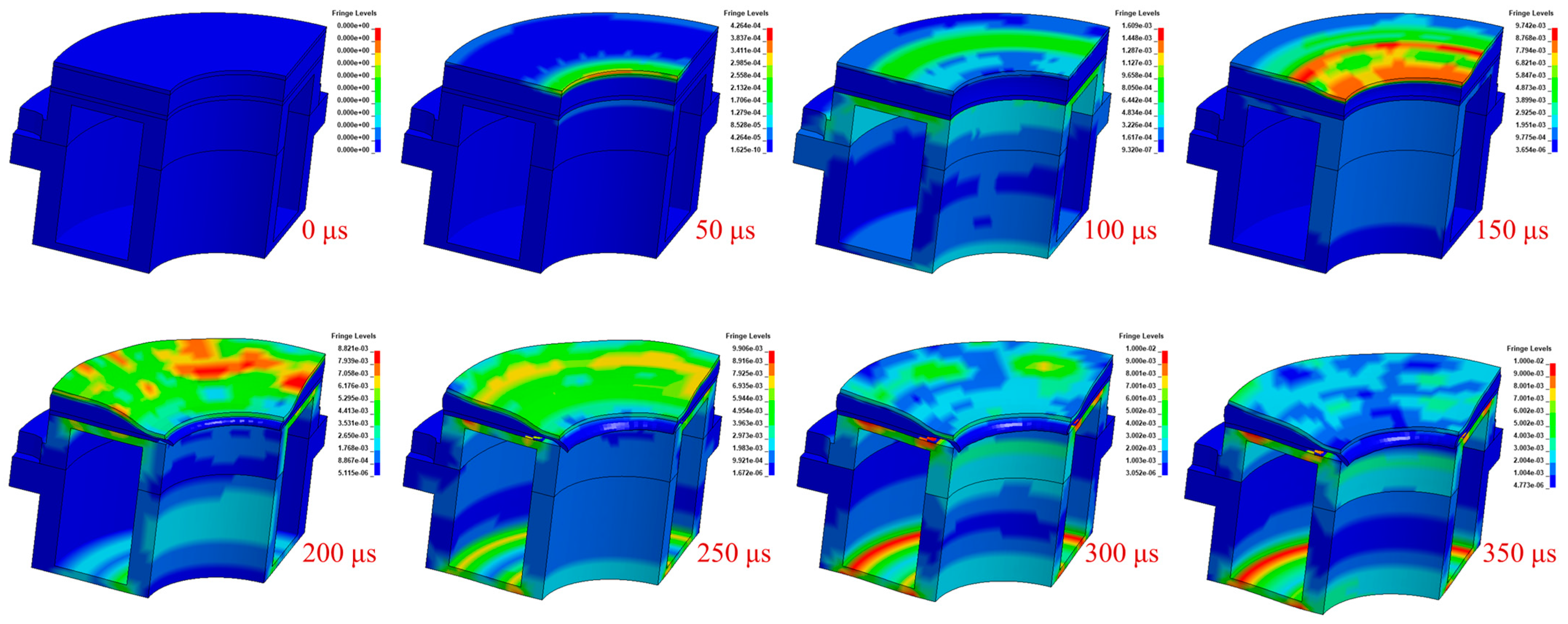
5.3. Numerical Calculation Results

According to the finite element model of the shaped-charge–blasting composite damage warhead established above, the finite element software was used for numerical calculation to obtain the shock wave transmission process and the response behaviors of the fuze and sandwich structure under the explosion of the shaped-charge warhead. During the calculation, the initiation time was set to 0 μs, the calculation step was set to 1 μs and the total time was 500 μs. The four main moment points of explosion simulation are shown in Figure 21.
Under the blast load, the sandwich structure gradually deformed, and even the bottom panel sustained local damage. The strain nephogram of the sandwich structure is shown in Figure 22. It is noticed that collapse and fragments occur in the bottom panel made of PTFE, signifying the destruction of structural integrity, which can be regarded as “failure”.
The deformation of the sandwich structure following the calculation is displayed in Figure 23, which illustrates that the sandwich structure had undergone enormous deformation: the top steel panel had the evident plastic deformation, the local compression deformation of foam-aluminum core reached 90% and the bottom panel made of PTFE had a local failure.
The deformation data of the foam-aluminum core were measured, and the position–deformation curve of foam-aluminum core of the sandwich structure under the blast load of the shaped-charge warhead explosion was obtained. The deformation data of foam-aluminum core obtained by simulation were compared with the experimental data, as shown in Figure 24.
The statistical error Ei of the deformation quantity at each measurement point is as follows:
E i = D i t D i s D i t
The total average error E of deformation quantity for foam aluminum core can be followed as:
E = 1 n E i n
where   D i t is the test data of point i,   D i s is the simulation data of point i; E i data are shown in Figure 25.
According to the error Ei, from Equation (5) it can be obtained that the total average error is E = 8.27%.
After the simulation calculation, the acceleration–time curve of the fuze under the blast load of the shaped-charge warhead explosion was established. The overload−time characteristic simulation data of the fuze were compared to the test results. The comparison diagram is shown in Figure 26.
From Figure 26 it can be seen that the simulation data of overload–time characteristics under the blast load of the shaped-charge warhead explosion have the same trend and similar peak value as the test data. The characteristics of overload peak value and pulse width (time interval of 10% of peak value) are extracted from the overload–time characteristic curve, as shown in Table 7.
In conclusion, the simulation data of the deformation quantity of foam-aluminum core were further compared to the test results, with a comprehensive error of 8.27%. The simulation data of the acceleration signals of the fuze were compared to the test results. The peak error is 8.54%, and the pulse width (taking the time interval of 10% of the peak value) error is 7.79%. The analysis results indicate that the model of the shaped-charge–blasting composite damage warhead is effective and accurate, which can be used to design sandwich structure.

6. Results and Discussion

The test and simulation results show that the steel panels of the structure based on foam-aluminum core have local failure. The sandwich structure is designed on foam-aluminum core.

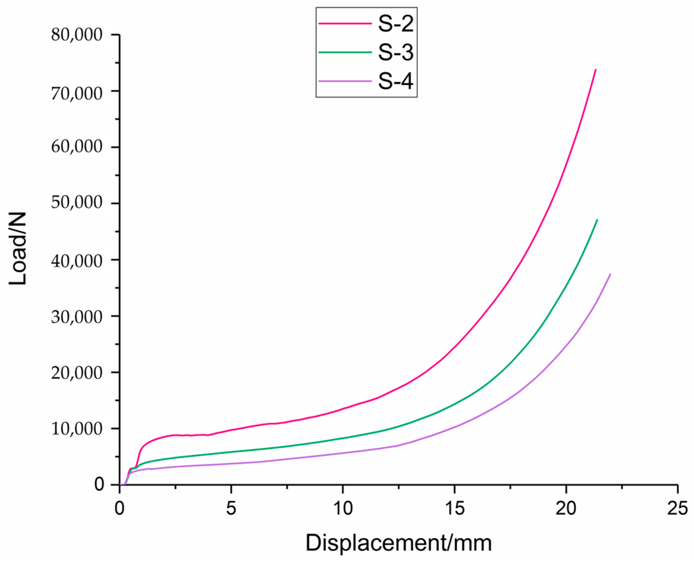
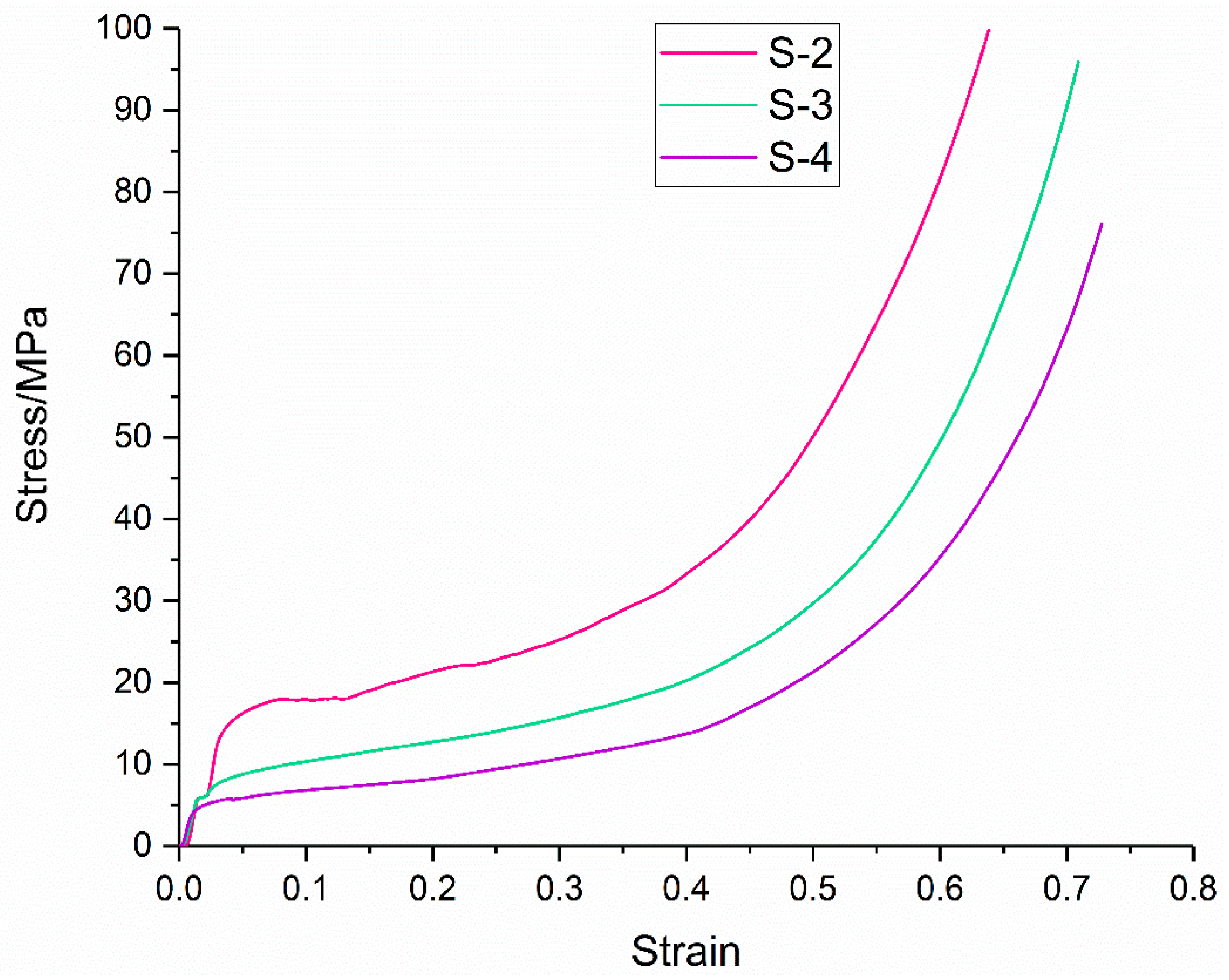
6.1. Mechanical Property Test of the Other Type 3 Foam-Aluminum Material Specimens

The test and simulation used foam–aluminum material with a diameter of 5–6 mm of spherical cell chamber. In the subsequent calculation, the sandwich core material uses foam-aluminum material with a diameter of 4–5 mm, 6–7 mm and 7–8 mm of the spherical cell chamber, as shown in Table 8. The mechanical property test specimen made of the above type 3 foam-aluminum material is shown in Figure 27.
The structural characteristics of the other three types of foam-aluminum displayed in Figure 27 are shown in Table 8.
The material performance tests were carried out by the DDL-100 testing machine to test the deformation data of the other three types of foam-aluminum specimens, and the corresponding data are shown in Figure 28.
The stress–strain curves of the other three types of foam-aluminum are established according to laboratory test data, as shown in Figure 29.

6.2. Simulation Comparison of Protective Performance of Four Foam-Aluminum Core Materials

According to the above finite element model, established for the shaped-charge–blasting composite damage warhead, the vast majority of parameters remained unchanged except for replacing the material parameters of foam-aluminum core. The deformation of foam-aluminum core for four types of sandwich structure under the blast load of the shaped-charge warhead was calculated, as shown in Figure 30.
The simulation results indicate that, under the blast load, the foam-aluminum panel of structure absorbed the blast energy. The position–deformation data of four types of foam-aluminum panels are shown in Figure 31.
When the density of foam-aluminum core is 1.20 g/cm3 and the diameter of the cell chamber is 4–5 mm, the deformation range of foam-aluminum core material is 0.42–7.56 mm; when the density of foam-aluminum core material is 1.12 g/cm3 and the diameter of the cell chamber is 5–6 mm, the deformation range of foam-aluminum core material is 1.07–8.32 mm; when the density of foam-aluminum core material is 0.98 g/cm3 and the diameter of the cell chamber is 6–7 mm, the deformation range of foam-aluminum core material is 3.55–7.71 mm; when the density of foam-aluminum core material is 0.90 g/cm3 and the diameter of the cell chamber is 7~8 mm, the deformation range of foam-aluminum core material is 3.10–8.63 mm. These results indicate that, with the decrease in the density of the foam-aluminum core material and the increase in the cell diameter, the deformation increases gradually.
After the simulation calculation, the overload−time characteristics curve of the fuze under the explosive blast of the shaped−charge warhead was established. Under the explosion blast, the simulation data of overload−time characteristics of fuze based on four types of foam-aluminum core materials are further compared and analyzed, as shown in Figure 32.
The comparison of overload–time characteristics of fuze with the protection of sandwich structures, based on four types of foam-aluminum core materials, obtained from Figure 32, is shown in Table 9.
The comparison of overload–time characteristics of fuze with the protection of sandwich structures based on four types of foam-aluminum core materials, obtained from Table 9, is shown in Figure 33.
As can be seen from Figure 33, as the density of the foam-aluminum core gradually decreases and the cell chamber diameter gradually increases, the overload of the fuze decreases gradually. However, the pulse width barely changes and remains basically constant.
Under the explosion blast, the deformation–time characteristics of the fuze’s upper cover are shown in Figure 34.
In Table 10, when the density of foam-aluminum core material is 1.20 g/cm3 and the diameter of the cell chamber is 4–5 mm, the maximum displacement deformation of the fuze upper cover is 2.494 mm, and the maximum deformation time is 368 μs. When the density of foam-aluminum core material is 1.12 g/cm3 and the diameter of the cell chamber is 5–6 mm, the maximum displacement deformation of the fuze’s upper cover is 2.495 mm, and the maximum deformation time is 369 μs. When the density of foam-aluminum core material is 0.98 g/cm3 and the diameter of the cell chamber is 6–7 mm, the maximum displacement deformation of the fuze’s upper cover is 2.458 mm, and the maximum deformation time is 367 μs. When the density of foam-aluminum core material is 0.90 g/cm3 and the diameter of the cell chamber is 7~8 mm, the maximum deformation of the fuze’s upper cover is 2.478 mm, and the maximum displacement deformation time is 372 μs.
The comparison results of the deformation characteristics of fuze with the protection of sandwich structures, based on four types of foam-aluminum core materials, is shown in Figure 35.
As can be seen from Figure 35, as the density of the foam-aluminum core gradually decreases and the cell chamber diameter gradually increases, the maximum displacement deformation of the fuze cover decreases firstly and then increases. The moment when the maximum deformation occurs decreases firstly and then increases. When the density of foam-aluminum core material is 0.98 g/cm3 and the diameter of the cell chamber is 6–7 mm, the deformation of the fuze cover is the smallest, which is considered as the best core material choice for a sandwich structure.
Under the explosion blast, the stress–time diagram of the fuze upper cover is shown in Figure 36, with the protection of sandwich structures based on four types of foam-aluminum core materials.
The comparison of stress–time characteristics of the fuze’s upper cover with the protection of sandwich structures based on four types of foam-aluminum core materials, obtained from Figure 36, is shown in Table 11.
As can be seen from Figure 36, when the density of foam-aluminum core material is 1.12 g/cm3 and the diameter of the cell chamber is 4–5 mm, the peak stress of the fuze’s upper cover starts at 258 μs and ends at 317 μs, then the peak stress hold-up time is about 59 μs. When the density of foam-aluminum core material is 1.2 g/cm3 and the diameter of the cell chamber is 5~6 mm, the peak stress of the fuze’s upper cover starts at 261 μs and ends at 325 μs, then the peak stress hold-up time is about 64 μs. When the density of foam-aluminum core material is 0.98 g/cm3 and the diameter of the cell chamber is 6–7 mm, the peak stress of the fuze’s upper cover starts at 264 μs and ends at 332 μs, then the peak stress hold-up time is about 68 μs. When the density of foam-aluminum core material is 0.90 g/cm3 and the diameter of the cell chamber is 7~8 mm, the peak stress of the fuze’s upper cover starts at 267 μs and ends at 341 μs, then the peak stress hold-up time is about 74 μs.
The comparison of results of the deformation characteristics of the fuze cover with the protection of sandwich structures, based on four types of foam-aluminum core materials, is shown in Figure 37.
As can be seen from Figure 37, with the gradual reduction of the density of foam-aluminum core materials and the gradual increase of the cell chamber diameter, the start time and end time of the peak stress of the fuze cover gradually lag behind, and the peak stress hold-up time increases gradually.

7. Conclusions

The experimental and numerical study on the response of the foam sandwich panels under near-field blast loading was carried out. In this paper, the numerical model of shaped-charge–blasting composite damage warhead and the sandwich structure model, based on foam-aluminum core material, are established. The typical deformation of sandwich structure, based on foam-aluminum core materials, with different densities and cell chamber diameters, was calculated and analyzed in detail, respectively. Meanwhile, the typical deformation of fuze cover and the overload of the fuze were also calculated and analyzed. This study is expected to provide the basic data and design guidelines for the graded foam sandwich panels of the blasting warhead fuze against near-field blast load.
(1)
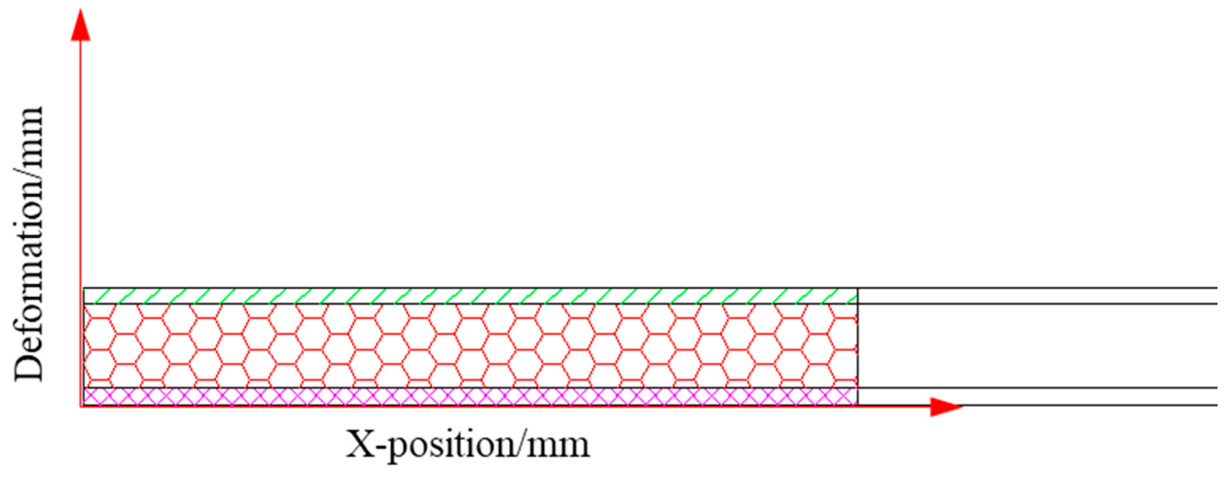
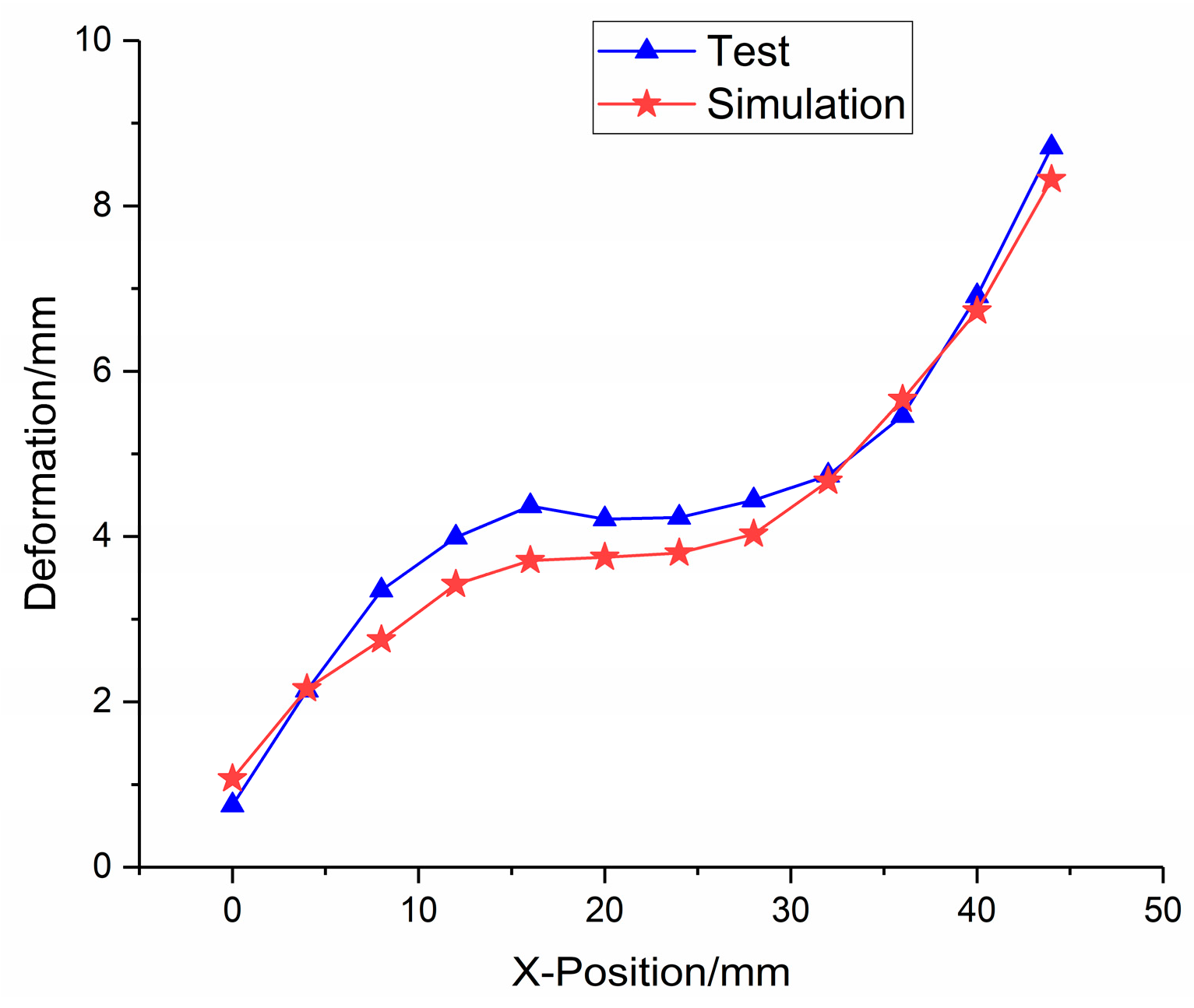
The simulation data of the position–deformation characteristics of the foam-aluminum core material were further compared to the test results, with a comprehensive error of 8.27%. The simulation data of the acceleration characteristics of the fuze were compared with the test results. The peak error is 8.54%, and the pulse width (taking the time interval of 10% of the peak value) error is 7.79%. The analysis results indicate that the model of the shaped-charge–blasting composite damage warhead is reasonable and accurate.
(2)
The test and simulated results indicate that the sandwich structure, consisting of foam-aluminum core material, can effectively attenuate the blast impact wave. The top steel panel can be successfully used to insulate the first-order explosive products and provide structural support for the sandwich structure; meanwhile, the foam-aluminum core material is used to rapidly absorb the blast wave and provide a larger deformation space for the entire structure. The bottom panel is made of PTFE, which can attenuate the blast wave again.
(3)
With the decrease of the density of foam-aluminum core material and the increase of the cell chamber diameter, the deformation of the foam-aluminum panel increases gradually.
(4)
As the density of the foam-aluminum core material gradually decreases and the cell chamber diameter gradually increases, the overload of the fuze decreases gradually. However, the pulse width barely changes and remains basically constant.
(5)
As the density of the foam-aluminum core material gradually decreases and the cell chamber diameter gradually increases, the maximum displacement deformation of the fuze cover decreases firstly and then increases. The moment when the maximum deformation occurs decreases firstly and then increases. When the density of the foam-aluminum core material is 0.98 g/cm3 and the diameter of the cell chamber is 6–7 mm, the deformation of the fuze cover is the smallest, which is considered as the best core material choice for a sandwich structure.
(6)
As the density of the foam-aluminum core material gradually decreases and the cell chamber diameter gradually increases, the start time and end time of the peak stress of the fuze cover gradually lag behind, and the peak stress hold-up time increases gradually.

Author Contributions

Conceptualization, P.X. and N.Z.; methodology, P.X., K.S. and B.Z.; software, P.X.; validation, K.S.; formal analysis, P.X. and N.Z.; investigation, P.X. and B.Z.; data curation, N.Z. and B.Z.; writing—original draft preparation, P.X.; writing—review and editing, B.Z.; supervision, N.Z. and K.S.; funding acquisition, B.Z. All authors have read and agreed to the published version of the manuscript.

Funding

This research was funded by the National Natural Science Foundation of China (No. 12202356).

Data Availability Statement

Data presented in this article are available upon request from the corresponding author.

Conflicts of Interest

The authors declare no conflict of interest.

References

  1. Lu, F.Y.; Li, X.Y.; Lin, Y.L. Structure and Principle of Warhead; Science Press: Beijing, China, 2009. [Google Scholar]
  2. Li, R.; Li, W.B.; Guo, X.D.; Liang, L.; Li, W.B.; Wang, X.M. Effect of the annular multi-point initiation control parameters on jet formation. Propellants Explos. Pyrotech. 2019, 44, 127–137. [Google Scholar] [CrossRef]
  3. Fedorov, S.V. On an experimental setup for the determination of the penetration capability of the tail sections of shaped-charge jets. Tech. Phys. 2021, 66, 724–733. [Google Scholar] [CrossRef]
  4. Wang, Y.; Yin, J.; Zhang, X.; Yi, J. Study on penetration mechanism of shaped-charge jet under dynamic conditions. Materials 2022, 15, 7329. [Google Scholar] [CrossRef]
  5. Chen, J.; Feng, D.; Sun, Q.; Peng, C.; Zhu, Y.; Yu, S. Numerical modeling of shaped charge jet penetration into ceramic–metal double-layered medium using smoothed particle hydrodynamics. Int. J. Impact. Eng. 2023, 175, 104526. [Google Scholar] [CrossRef]
  6. Xu, W.L.; Wang, C.; Chen, D.P. Formation of a bore-center annular shaped charge and its penetration into steel targets. Int. J. Impact. Eng. 2019, 127, 122–134. [Google Scholar] [CrossRef]
  7. Du, Y.; He, G.; Liu, Y.; Guo, Z.; Qiao, Z. Study on penetration performance of rear shaped charge warhead. Materials 2021, 14, 6526. [Google Scholar] [CrossRef]
  8. Wang, L.; Han, X.; Wang, L.; Ruan, G.; Xin, P.; Li, N.; Huang, Y.; Zheng, W. New explosive composite armor technology for light armored vehicles. Int. Symp. Adv. Lau. Tech. 2023, 2460, 012136. [Google Scholar] [CrossRef]
  9. Xu, W.L.; Wang, C.; Chen, D.P. The jet formation and penetration capability of hypervelocity shaped charges. Int. J. Impact Eng. 2019, 132, 103337. [Google Scholar] [CrossRef]
  10. Guo, H.G.; Zheng, Y.F.; Yu, Q.B.; Wang, H.F. Penetration behavior of reactive liner shaped charge jet impacting thick steel plates. Int. J. Impact Eng. 2019, 126, 76–84. [Google Scholar] [CrossRef]
  11. Dehestani, P.; Fathi, A.R.; Mohammadi, D.H. Numerical study of the stand-off distance and liner thickness effect on the penetration depth efficiency of shaped charge process. J. Mech. Eng. Sci. 2018, 233, 977–986. [Google Scholar] [CrossRef]
  12. Wang, H.F.; Guo, H.G.; Ge, B.Q.; Yu, Q.B.; Zheng, Y.F. Application of PTFE/Al reactive materials for double-layered liner shaped charge. Materials 2019, 12, 2768. [Google Scholar] [CrossRef] [PubMed]
  13. Sun, J.; Ma, Z.; Zhang, Z.; Weng, F.; Chen, R. The delamination of carbon fiber reinforced composites during cutting by flexible linear shaped charge. J. Mech. Sci. Tech. 2020, 34, 1515–1522. [Google Scholar] [CrossRef]
  14. Minel, S. Numerical simulations of the formation behavior of explosively formed projectiles. Defen. Sec. Stu. Origin Res. 2022, 3, 1–14. [Google Scholar]
  15. Ding, L.L.; Tang, W.H.; Ran, X.W. Simulation study on jet formability and damage characteristics of a low-density material liner. Materials 2018, 11, 72. [Google Scholar] [CrossRef] [PubMed]
  16. Weng, D.W. Research status and development trend of protection materials for tank armored vehicles. Met. Mater. 2019, 39, 43–64. [Google Scholar]
  17. Kou, P.F.; Cao, L.; Liang, Z.F. Research status and development trend of tandem shaped charge warhead technology. J. Ord. Equip. Eng. 2022, 43, 155–161. [Google Scholar]
  18. Lv, J.; Wang, W.L.; Li, Y.S. Optimization of materials on explosion-proof body for tandem warhead with front annular cutter. J. Proj. Rocket. Missiles Guid. 2014, 34, 105–109. [Google Scholar]
  19. Liu, H.J.; Wang, W.L.; Miao, R. Explosive interruption of tandem warhead with different multilayer structures. Chin. J. High Press Phy. 2019, 33, 148–160. [Google Scholar]
  20. Ke, M.; Fan, R.Y.; Wu, H.J. Adaptivity of travelling projectile of tandem warhead to caliber of precursor charge and initial attitude. Binggong Xuebao/Acta Armamentarii. 2021, 42, 22–32. [Google Scholar]
  21. Rimoli, J.J.; Talamini, B. Wet-sand impulse loading of metallic plates and corrugated core sandwich panels. Int. J. Impact Eng. 2011, 38, 837–848. [Google Scholar] [CrossRef]
  22. Tarlochan, F.; Ramesh, S.; Harpreet, S. Advanced composite sandwich structure design for energy absorption applications: Blast protection and crashworthiness. Compos. Part B 2012, 43, 2198–2208. [Google Scholar] [CrossRef]
  23. Wang, Z.; Jing, L. The structural response of clamped sandwich beams subjected to impact loading. Compos. Struct. 2011, 93, 1300–1308. [Google Scholar] [CrossRef]
  24. Xi, H.; Tang, L.; Luo, S.; Liu, Y.; Jiang, Z.; Liu, Z. A numerical study of temperature effect on the penetration of aluminum foam sandwich panels under impact. Compos. Part B Eng. 2017, 130, 217–229. [Google Scholar] [CrossRef]
  25. Zhu, L.; Guo, K.; Li, Y.; Yu, T.; Zhou, Q. Experimental study on the dynamic behaviour of aluminium foam sandwich plates under single and repeated impacts at low temperature. Int. J. Impact Eng. 2018, 114, 123–132. [Google Scholar] [CrossRef]
  26. Sun, G.; Chen, D.; Huo, X.; Zheng, G.; Li, Q. Experimental and numerical studies on indentation and perforation characteristics of honeycomb sandwich panels. Compos. Struc. 2018, 184, 110–124. [Google Scholar] [CrossRef]
  27. Sun, G.; Huo, X.; Chen, D.; Li, Q. Experimental and numerical study on honeycomb sandwich panels under bending and in-panel compression. Mater. Des. 2017, 133, 154–168. [Google Scholar] [CrossRef]
  28. McShane, G.J.; Radford, D.D.; Deshpande, V.S.; Fleck, N.A. The response of clamped sandwich plates with lattice cores subjected to shock loading. Eur. J. Mech. 2006, 25, 215–229. [Google Scholar] [CrossRef]
  29. Xu, P.; Zhao, N.; Chang, Y.; Cui, S.; Shi, K.; Zhang, B. Experimental and numerical study on dynamic response of foam-nickel sandwich panels under near-field blast loading. Materials 2023, 16, 5640. [Google Scholar] [CrossRef] [PubMed]
  30. Liu, W.; Wu, L.; Sun, X. PTFE energy absorber of explosive initiator under high-g loding. In Proceedings of the 2015 Aasri International Conference on Industrial Electronics & Applications, London, UK, 27–28 June 2015. [Google Scholar]
Figure 1. Results of laboratory mechanistic experimental test. (a) Foam-nickel sandwich panels [29]. (b) Foam-aluminum sandwich panels.
Metals 13 01745 g001
Figure 2. Schematics of the shaped-charge–blasting composite damage warhead.
Metals 13 01745 g002
Figure 3. Schematic diagram of combined damage warhead experimental test.
Metals 13 01745 g003
Figure 4. Sandwich structure diagram made of foam-aluminum core.
Metals 13 01745 g004
Figure 5. Foam-aluminum core material.
Metals 13 01745 g005
Figure 6. Geometric model and real object of fuze for the explosive warhead. (a) Geometric model (b) Material object.
Metals 13 01745 g006
Figure 7. Secondary-packaged acceleration sensor. (a) Geometric model. (b) Sensor object.
Metals 13 01745 g007
Figure 8. Instantaneous images of detonation.
Metals 13 01745 g008
Figure 9. Product recovery after the blast test.
Metals 13 01745 g009
Figure 10. Sectional drawing of the test fuze.
Metals 13 01745 g010
Figure 11. Schematic diagram of deformation measurement coordinates.
Metals 13 01745 g011
Figure 12. Position–deformation diagram of foam-aluminum core material.
Metals 13 01745 g012
Figure 13. Acceleration−time curve of fuze.
Metals 13 01745 g013
Figure 14. Foam-aluminum specimen.
Metals 13 01745 g014
Figure 15. DDL-100 electronic universal testing machine.
Metals 13 01745 g015
Figure 16. Mechanical property test process. (a) Before the test. (b) During the test. (c) After the test.
Metals 13 01745 g016
Figure 17. Displacement–load curve of foam-aluminum.
Metals 13 01745 g017
Figure 18. Geometric model of shaped-charge–blasting composite damage warhead.
Metals 13 01745 g018
Figure 19. Simulation model.
Metals 13 01745 g019
Figure 20. Stress–strain curve of the foam-aluminum.
Metals 13 01745 g020
Figure 21. Schematic diagram of the explosion process.
Metals 13 01745 g021
Figure 22. Diagram of deformation process of sandwich protective structure.
Metals 13 01745 g022
Figure 23. Deformation and failure performances of the sandwich structure.
Metals 13 01745 g023
Figure 24. Comparison of the deformation data for foam-aluminum core between the simulation and test.
Metals 13 01745 g024
Figure 25. Simulated error of deformation data at each measuring point.
Metals 13 01745 g025
Figure 26. Comparison of acceleration signals of fuze between simulation and test.
Metals 13 01745 g026
Figure 27. Mechanical property test piece of foam-aluminum material.
Metals 13 01745 g027
Figure 28. Displacement–load diagram of three types of foam-aluminum specimens.
Metals 13 01745 g028
Figure 29. Stress–strain curve of three types of foam-aluminum specimens.
Metals 13 01745 g029
Figure 30. Deformation diagram of four types of foam-aluminum core materials.
Metals 13 01745 g030
Figure 31. Position–deformation data diagram of four types of foam-aluminum core materials.
Metals 13 01745 g031
Figure 32. Overload−time characteristics comparison diagram.
Metals 13 01745 g032
Figure 33. Relation between the overload and a cell diameter of foam-aluminum core.
Metals 13 01745 g033
Figure 34. Deformation−time diagram of fuze’s upper cover. The comparison of deformation characteristics of fuze with the protection of sandwich structures based on four types of foam-aluminum core materials, obtained from Figure 34, is shown in Table 10.
Metals 13 01745 g034
Figure 35. Relationship between deformation characteristics and cell diameter of foam-aluminum core.
Metals 13 01745 g035
Figure 36. Stress–time diagram of fuze upper cover.
Metals 13 01745 g036
Figure 37. Comparison between the peak stress hold-up time and cell diameter of foam-aluminum.
Metals 13 01745 g037
Table 1. Parameters of the 8701 explosive [27].
ρ (g/cm3)D (cm/s) A(Gpa) B (Gpa) ω R 1 R 2 E (GPa) V
1.68 0.88852.418.020.384.51.38.51
Table 2. Material parameters of the shaped-charge liner [22].
ρ0 (g/cm3)G (GPa)A (MPa)B (MPa)nCM
8.96047.7902400.220.0032.2
Cp (J/kg∙K)Tm (K)D1D2D3D4D5
88810140.1160.2112.171990.0120.01256
Table 3. Material parameters of the bulkhead and cover plate.
Materialρ0
(g/cm3)
E
(GPa)
NUXYYield Stress
(MPa)
2024 AL2.78072.40.33345
30CrMnSiNi2A Steel 7.7802050.31720
Table 4. Material parameters of the steel [22].
ρ0 (g/cm3)E (GPa)A (MPa)B (MPa)nCM
7.847.75073200.280.0641.06
Cp (J/kg∙K)Tm (K)D1D2D3D4D5
46917950.10.761.570.005−0.84
Table 5. Material parameters of the PTFE [30].
Materialρ0
(g/cm3)
E
(GPa)
NUXYYield Stress
(MPa)
PTFE2.1802.250.418
Table 6. The material parameter of foam-aluminum.
Materialρ0
(g/cm3)
E
(GPa)
NUXY
foam-aluminum1.1200.650.287
Table 7. Comparison between simulated and measured data.
Measured ResultsSimulation Calculation ResultsError
Overload peak (g)1.64 × 1041.50 × 1048.54%
Pulse width (μs)77837.79%
Table 8. The structural characteristics of the other three types of foam-aluminum specimens.
SpecimenDensity
(g/cm3)
Cell Diameter
(mm)
S–21.24~5
S–30.986~7
S–40.97~8
Table 9. Comparison of overload–time characteristics.
SpecimenDensity
(g/cm3)
Cell Diameter
(mm)
Overload Peak
(g)
Pulse Width
(μs)
S−11.125~61.50 × 10⁴ 83
S−21.204~51.59 × 10⁴ 82
S−30.986~71.43 × 10⁴ 81
S−40.907~81.35 × 10⁴ 82
Table 10. Comparison of deformation characteristics of fuze’s upper cover.
SpecimenDensity
(g/cm3)
Cell Diameter
(mm)
Maximum Deformation
(mm)
Maximum Deformation Moment
(μs)
S−11.125~62.495369
S−21.204~52.494368
S−30.986~72.458367
S−40.907~82.478372
Table 11. Comparison of stress–time characteristics of fuze upper cover.
SpecimenDensity
(g/cm3)
Cell Diameter
(mm)
Peak Stress Start Time
(μs)
Peak Stress End Time
(μs)
Peak Stress Hold-Up Time
(μs)
S–11.125~626132564
S–21.204~525831759
S–30.986~726433268
S–40.907~826734174
Disclaimer/Publisher’s Note: The statements, opinions and data contained in all publications are solely those of the individual author(s) and contributor(s) and not of MDPI and/or the editor(s). MDPI and/or the editor(s) disclaim responsibility for any injury to people or property resulting from any ideas, methods, instructions or products referred to in the content.

