Abstract
This study analyzed the influence of tempering treatment temperature on the microstructural and mechanical behavior of two different powder metallurgy steels containing 0 wt. % Ni and 4 wt. % Ni. The evolution of the microstructure and the macro- and microhardness of the microstructural constituents resulting from tempering treatments conducted on the sinter-hardened materials at temperatures ranging from 160 °C to 300 °C were investigated. The role of the tempering conditions in the impact behavior was assessed using Charpy tests on V-notched and unnotched samples, tempered at 180 °C, 220 °C and 280 °C. The observed macrohardness reduction with increasing tempering temperature was related to martensite transformations. At high tempering temperatures, the remarkable loss in impact energy values was attributed to microfracture modes. The contribution of Ni-rich austenite areas in enhancing impact strength was detected.
1. Introduction
Powder metallurgy (PM) is a promising technology for the cost-effective production of near-net shape components across several engineering industries. PM steels find extensive applications in the automotive field, meeting the demand for complex and multifunctional parts, e.g., engine, transmission, brake, chassis and electromagnetic components [1,2,3,4]. On the industrial scale, PM steels can compete with conventional steels and are broadly employed in gear manufacturing, where wear, fatigue and dynamic resistance are crucial [5]. Ongoing efforts are mainly devoted to the reliability of engineering systems [6,7,8] and improvements in materials’ properties [9,10,11]. For instance, in the case of machinery operating with contaminated fluids, erosion and deposition phenomena [12,13,14] induce long-term alterations in the material’s structure, resulting in performance deterioration, heightened noise and vibration, and ultimately, premature and unforeseen component failure [15,16,17].
Among other factors, composition of the powder blend, compaction pressure, sintering conditions and post-sintering heat treatments affect the porosity and the resulting microstructure, which, in turn, control the behavior of the final parts [18]. PM components intended for high-stress applications may often require a post-sintering heat treatment to attain the desired strength and apparent hardness. To reduce the need for supplementary steps, a cost-effective solution is the sinter-hardening process, which integrates the sintering and hardening phases into one single phase in a continuous furnace, using inert gas cooling immediately after sintering to achieve the desired hardening effect [19].
As PM steels are often alloyed with high C content to increase apparent hardness, a post-sintering tempering treatment is necessary to restore their mechanical properties [20,21,22,23,24]. The specific tempering temperature is crucial and can be related to several factors, including C content, targeted mechanical properties (e.g., tensile, fatigue, impact or tribological resistance) and hardness. To date, several studies have attempted to analyze the influence of tempering on the above-described properties. Chagnon and Gagnè [22] evaluated the effect of tempering temperature on the tensile properties, apparent hardness, impact energy and microstructure of two PM materials tempered for 60 min at temperatures ranging from 150 °C to 600 °C. They observed a reduction in apparent hardness, due to the formation of cementite, for samples tempered in the range of 200–400 °C. In the as-sintered condition, the low ultimate tensile strength (UTS) values were related to the brittleness of untempered martensite, while the highest yield strength (YS) was measured after tempering at 300 °C, and resulted from the complete transformation of retained austenite into bainite. More recently, Hatami et al. [23] sought to improve the low toughness of a pre-alloyed 3Cr–0.5Mo PM steel using tempering treatments performed at 200 °C, 400 °C, 550 °C and 650 °C for different times. The best combination of hardness, toughness and tensile strength was found for a tempering route of 200 °C for 1 h, while the highest elongation and impact strength were obtained after tempering at 650 °C for 30 min.
In addition to post-sintering heat treatment routes, higher material performances can be tuned by alloying elements such as Cr, Mo, Ni, Mn and Cu [25,26,27,28,29]. With specific reference to Ni, its role in improving strength, impact and fatigue resistance has been assessed [30,31]. To date, in PM steel powder blends, it is common to add Ni in the range of 1 to 4 wt. % [32,33], albeit that ongoing efforts are focused on minimizing alloying elements [30,34]. From a microstructural perspective, the heterogeneous distribution of Ni-rich areas gained attention in the literature, and the effect of combinations of complex microstructural constituents after sintering and post-sintering treatments on mechanical properties needs further understanding [31,35,36,37]. Specifically, even though hardness, tensile and fatigue resistance have been widely investigated and there is deeper understanding of the factors that influence them, few studies have addressed the toughness of PM steels [26,33,34,35,36,37,38]. As a general comment, PM steels exhibit poor toughness, primarily due to high porosity, which impairs their use in high-demanding applications. In light of this, efforts have been devoted to enhancing the impact behavior of PM steels, resulting in promising perspectives. To the best of the authors’ knowledge, specific studies focused on the effect of tempering temperature on the impact strength of PM steels are limited [35].
Within this context, the present study addresses the interaction between tempering temperature and chemical composition in the microstructural and mechanical behavior of PM steels. The paper begins with a synopsis of the literature on PM steels, focusing on the role of microstructural features in affecting their mechanical behavior, specifically for impact load conditions. Section 2 outlines the materials and the experimental methodologies used in this study to assess the microstructural, hardness and mechanical properties as a function of the tempering treatments performed. Section 3 details the experimental findings regarding microstructural characterization in the sinter-hardened and tempered conditions, hardness values, and impact behavior. Lastly, Section 4 discusses the results obtained, referring to previous studies and focusing on the role of Ni content and tempering temperature in affecting the mechanical response and the fractographic aspects.
The novelty of the present paper consists in its investigation of tempering treatment temperatures on the impact strength of PM steels, examining the role of Ni content and the evolution of the microstructural constituents. To that end, two commonly used industrial powder mixes were chosen, having the minimum and the maximum values of the typical Ni composition range. As a result of the analysis in this study, indications and guidelines can be articulated to manage the Ni content and the heat treatment strategy.
2. Materials and Methods
The study was conducted using samples produced from a diffusion-bonded steel powder (Höganäs Distaloy® powder mixture) supplied by Höganäs AB (Höganäs, Sweden). To investigate the role of Ni, two different industrial powder mixes were considered. Table 1 summarizes the nominal chemical composition of the investigated PM steels; the code, the base alloy and the lubricant used are also specified. As can be seen, a higher C content was added in the 0Ni powder to compensate for the lower alloy content to promote the hardenability of the material.

Table 1.
Nominal chemical composition (wt.%) of the investigated materials.
The samples were compacted in a uniaxial double action press and sintered at 1150 °C for 60 min in a continuous belt furnace in an endogas atmosphere. The samples were then hardened at a cooling rate of 4 °C/s. According to the manufacturer, the density after sintering was 7.0 g/cm3. In the as-received condition, i.e., after sinter-hardening treatment, the samples consisted of five discs for each of the 0Ni and the 4Ni compositions, measuring 100 mm in diameter and 6 mm in height. For each composition, one disc was intended for the microstructural and hardness characterization and the remaining four for the impact tests.
The effect of tempering temperature on the microstructure was studied through tempering treatments conducted at 160 °C, 180 °C, 200 °C, 220 °C, 240 °C, 260 °C, 280 °C and 300 °C for 1 h (calm air cooling) on the 0Ni and 4Ni samples, respectively. All treatments were performed using an LTF (Lenton Furnaces and Ovens, Hope, UK) tube furnace.
Macrohardness measurements were performed using an automatic QATM Qness 60 CHD Master + (QATM, Golling an der Salzach, Austria) hardness tester, according to the ISO 4498:2010 standard. The mean Vickers macrohardness was evaluated using cross-sections cut from the above-described samples in both the sinter-hardened and the tempered conditions.
Macrohardness measurements were conducted under a 10 kgf (HV10) load and a dwelling time of 15 s, randomly acquired on the cross-sections. Metallographic analyses were carried out on the same cross-sections after conventional preparation, i.e., hot mounting in resin, grinding, and polishing with diamond suspension up to a 1 µm finish. Chemical etching with a mixed solution of Nital 4 (4% nitric acid in ethanol) and Picral (4 g picric acid in 100 mL ethanol) reagents was adopted to reveal the microstructure analyzed by a Leica DMi8 A light optical microscope (LOM) (Leica, Wetzlar, Germany). The area fraction of retained austenite in the 4Ni samples was measured using quantitative metallography: from the etched specimens, 20 optical micrographs at 200x magnification (total investigated area of 5.3 mm2) were randomly acquired and processed using the public domain ImageJ image analysis software (Version 1.53e, 2020, National Institutes of Health, Bethesda, MD, USA) [39]. Microhardness measurements were performed using the same QATM Qness 60 CHD Master + hardness tester under different applied loads and a dwelling time of 15 s for martensite (HV0.05), austenite (HV0.025) and transition regions (HV0.025). A more detailed microstructural investigation was carried out using a Zeiss EVO MA15 (Carl Zeiss, Jena, Germany) scanning electron microscope (SEM). The SEM images were recorded in secondary electron imaging (SEI-SEM) and back-scattered electron (BSE-SEM) modes.
Based on the microstructural and hardness outcomes, three tempering treatments were chosen for impact tests, i.e., 180 °C, 240 °C and 280 °C. The untempered condition was also tested. Following the ASTM E-23 standard, V-notched and unnotched subsize (5 mm × 10 mm × 55 mm) Charpy samples were machined from the discs using electrical discharge to prevent thermal degradation [40] and ground to fit the tolerance specifications. The impact strength was determined using a CEAST Resil Impactor pendulum (Instron-CEAST, Pianezza, Italy) (50 J of available energy). Impact tests were performed at room temperature (25 °C), and the impact energy was analyzed on three replicates for each condition. After the impact tests, the macroscopical appearance of the fracture profiles was detected using a Leica MZ6 (Leica, Wetzlar, Germany) stereomicroscope. Microfractographic observations of the fracture surfaces and the fracture profiles were analyzed using SEM to detect the micromechanisms of fracture and the crack path, respectively.
3. Results
3.1. As-Received Materials
Figure 1 shows the LOM micrographs of the investigated materials in the as-received condition, i.e., after sinter-hardening treatment. The microstructural constituents were identified as martensite, bainite and austenite. Martensite (labeled as M in Figure 1) was the principal constituent for both compositions, and bainite flakes were located at the center of the former powder particles (labeled as B in Figure 1). As for the 4Ni sample, retained austenite (labeled as A in Figure 1b) was preferentially located in islets near pores and sintering necks [30].
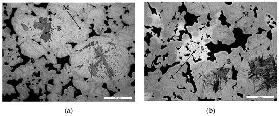
Figure 1.
LOM micrographs of the investigated materials in the as-received (sinter-hardened) condition: (a) 0Ni and (b) 4Ni. In (a,b): (A) retained austenite, (B) bainite and (M) martensite.
The 0Ni and 4Ni samples showed mean macrohardness of 427 ± 19 HV10 and 373 ± 13 HV10, respectively.
3.2. Tempering Treatments
Figure 2 shows the Vickers macrohardness (HV10) values for the two investigated compositions as a function of the tempering temperatures, ranging from 160 °C to 300 °C. As can be seen, the hardness evolution is similar. For both compositions, between 200 °C and 240 °C a decrease in mean macrohardness is detectable. By contrast, hardness values tend to be constant in the ranges from 160 °C to 180 °C and from 260 °C to 300 °C. It should be noted that the hardness of all the 0Ni samples is shifted towards higher values.

Figure 2.
Vickers macrohardness (HV10) mean values for the investigated tempering temperatures in 0Ni and 4Ni PM steels.
Accordingly, the study was focused on the analysis of three tempering temperatures, i.e., 180 °C, 220 °C and 280 °C. A temperature of 180 °C is located in the first hardness plateau, and is the reference for standard industrial treatment [19], while 220 °C is located in the hardness transition area, and 280 °C is located in the second hardness plateau.
The microstructural evolution during tempering treatments is summarized in the LOM micrographs of Figure 3. For the 0Ni composition, the microstructure mainly consisted of martensite and small amounts of bainite. In the 180 °C condition (Figure 3a), martensite showed two different morphologies: a darker and coarse one close to the pores and a lighter and fine one in the center of the former powder particles. On increasing the tempering temperature (Figure 3b,c), the martensite began to lose its tetragonality, and the difference between the two morphologies disappeared, leading to the formation of a uniform low-tetragonality martensite microstructure (Figure 3c). Concerning the 4Ni composition (Figure 3d–f), the martensite evolution was similar to the previously described one; moreover, changes in the retained austenite were observed. Figure 3f shows that the 280 °C tempering treatment caused the retained austenite to transform into an acicular structure close to the martensite boundaries, leading to the reduction in retained austenite areas. This aspect is detailed in the SEM micrographs in Figure 3.
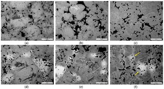
Figure 3.
LOM micrographs of the (a–c) 0Ni and (d–f) 4Ni after tempering treatments at: (a,d) 180 °C; (b,e) 220 °C and (c,f) 280 °C. Yellow arrows point to areas of transformed austenite.
The quantitative image analysis of the austenite transformation is summarized in Figure 4. The 180 °C tempering treatment did not affect the austenite content as compared with the untempered condition. Conversely, the results confirmed that for tempering temperatures of 220 °C and 280 °C, the austenite area fraction was reduced.
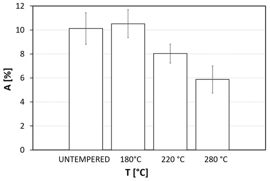
Figure 4.
Retained austenite area fraction (A) for the 4Ni samples evaluated for the untempered condition and the different tempering temperatures.
The microstructural evolution during tempering treatment was deeply investigated using SEM analyses. Figure 5 shows the BSE-SEM micrographs of the martensite matrix for the 0Ni and 4Ni samples tempered at different temperatures. The martensite appeared still tetragonal at 180 °C, with a needle-like morphology (Figure 5a,d). At 220 °C, the martensite transition occurred, and the typical plate martensite microstructure was detected (Figure 5b,e). This completed phase exhibited microstructural areas resembling those detected at 180 °C and others already transformed. Finally, at 280 °C, the depletion of C from martensite took place, with the formation of carbides inside the martensite plates (Figure 5c,f), suggesting that the microstructural transformations were completed.
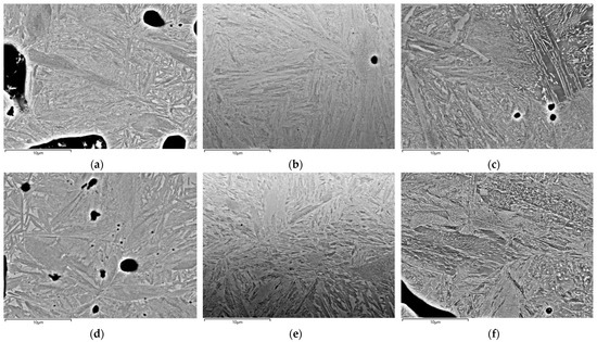
Figure 5.
BSE-SEM micrographs of the martensitic matrix of (a–c) 0Ni and (d–f) 4Ni after tempering treatments at: (a,d) 180 °C; (b,e) 220 °C and (c,f) 280 °C.
The deeper analysis of austenite transition regions for 4Ni samples is presented in Figure 6. Tempering at 180 °C did not promote remarkable microstructural changes, and no transitioning structures were detected (Figure 6a). Austenite (see Figure 6a on the right) was directly in contact with martensite (see Figure 6a on the left), which still maintained its tetragonality and was not affected by carbides precipitation. For the 220 °C condition (Figure 6b), a new type of plate martensite containing carbides was visible (see circled area). Austenite (see Figure 6b on the bottom) was partially affected by an acicular structure growth (see white arrow), with a preferential orientation towards the center of the islet.

Figure 6.
BSE-SEM micrographs of the transition regions between retained austenite and martensite in the 4Ni samples tempered at: (a) 180 °C, (b) 220 °C and (c) 280 °C. In (b), the circled area is the martensite with metastable ε carbides precipitation; the arrow indicates an acicular structure growth with preferential orientation.
At 280 °C (Figure 6c), the transition region involved an extensive formation of bainite-like structures rich in carbides, as was previously observed in [20,41]. These structures presented a preferential directionality of growth towards the center of the retained austenite islet (see Figure 6c). That indicated the decomposition of austenite in this new structure, thus confirming the LOM observations (see Figure 3d–f).
Table 2 compares the microstructural hardness for the two compositions in the different heat-treating conditions. As can be seen, regardless of the composition, martensite microhardness decreased as the tempering temperature increased. It is noticeable that the 0Ni composition showed higher values compared to the 4Ni composition due to the higher C content (see Table 1), which raised the martensite microhardness. As for the austenite and transition regions, they were present only in the 4Ni composition. Austenite hardness values were in the same range of 160–180 HV0.025 for all the investigated conditions. The transition regions, resulting from austenite transformation, exhibited values of about 450 HV0.025, which is consistent with the typical hardness of bainite [42].
Table 2.
Microhardness of the microstructural constituents for the 0Ni and 4Ni samples in untempered and tempered conditions.
3.3. Impact Tests and Fractography
Table 3 summarizes the results of impact energy tests for the investigated conditions. Impact energy values for the V-notched samples were around 1 J for all the samples, and no correlations could be detected. Conversely, the differences in impact energy values were enhanced for the unnotched condition. For all the conditions, the material’s toughness was improved by Ni content, especially for the untempered condition. For the tempered conditions, the difference in impact energy values between the 0Ni and 4Ni unnotched samples was around 1 J, while for the untempered condition, it was about 4 J. The untempered condition was detrimental to the 0Ni samples, while the 4Ni samples were less affected. As for the tempered conditions, the highest impact energy values were reached for the 180 °C treatment. In addition, as the tempering temperatures increased, the impact energy values decreased.
Table 3.
Average values with standard deviations of impact energies for investigated tempering temperatures of the 0Ni and 4Ni materials.
The representative stereomicroscope images of the macroscopic fracture profiles, produced in Figure 7, revealed brittle fracture paths with the surrounding material undeformed. These observations were common for all the investigated samples (unnotched and V-notched, 0Ni and 4Ni samples).

Figure 7.
Representative stereomicroscope images of the fracture profiles of the (a) V-notched and (b) unnotched samples.
Figure 8 compares the fracture surface morphologies in relation to the different conditions for 0Ni unnotched samples. For brevity, only the 0Ni case was reported, taking into account that the 4Ni behavior was comparable. Overall, the microscopical appearance of the fracture surface was not brittle, unlike the previous observations on the macroscopical scale (Figure 7). The different tempering conditions led to various fracture ductility levels. Figure 8a displays a mixed-mode fracture with the simultaneous presence of dimples and cleavage facets, albeit barely distinguishable from each other. The tempering treatment at 180 °C resulted in a microscopically ductile fracture mode with well-defined dimples (Figure 8b). At higher tempering temperatures (220 °C and 280 °C), a less ductile behavior was detectable (Figure 8c,d). The fracture shifted back to a mixed mode, as suggested by the presence of both cleavage areas and dimples, as previously observed. Of particular note was the large cleavage area detected in the fracture surface of the sample tempered at 280 °C (see black arrow in Figure 8d).

Figure 8.
SEI-SEM micrographs of the fracture surfaces of the 0Ni unnotched samples: (a) untempered and tempered at (b) 180 °C, (c) 220 °C and (d) 280 °C.
SEM analyses of the fracture surfaces enabled the detection of two main fracture modes common to all examined conditions. These modes are displayed in Figure 9 in a representative fracture surface (Figure 9a) and a fracture profile (Figure 9b). The sintering necks failed mainly by ductile mode under the action of a load normal to the surface, resulting in uniform and equiaxial dimples (see continuous lines in Figure 9). In addition, the former powder particles exhibit shear fracture paths, parallel to the applied load. Dimples appeared small and stretched with a fracture that resembled cleavage mode (see dashed lines in Figure 9).

Figure 9.
SEI-SEM micrographs of a fracture (a) surface and (b) profile. Continuous lines identify the ductile fracture of the sintering necks. Dashed lines indicate the shear rupture of the former powder particles.
Fracture profiles of the V-notched and unnotched samples are compared in the SEI-SEM micrographs in Figure 10. The amount and extension of secondary cracks (see white arrows in Figure 10) were noticeably higher for the unnotched samples. For the V-notched samples, secondary cracks were located within 50 µm distance from the main fracture path; conversely, for the unnotched samples, they were at distances of up to 200 µm.

Figure 10.
SEI-SEM micrographs of the fracture profiles of the (a) V-notched and (b) unnotched samples. Secondary cracks are highlighted by white arrows.
The response of Ni-rich areas to the fracture propagation was clearly elucidated by LOM and SEM fracture characterization. On a macroscopical scale, Ni-rich areas were very seldom crossed by the main crack front (Figure 11a). Fracture paths always chose the energetically convenient way for propagation, and thus pores and weak structures could be preferentially crossed. As for Ni-rich austenite areas, a peculiar behavior was observed, as detailed in the blow-up in Figure 11b: crack propagation could be stopped by the plastic deformation of Ni-rich areas.
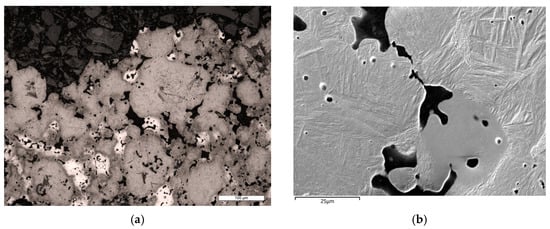
Figure 11.
Fracture paths in relation to Ni-rich austenite areas in 4Ni samples: (a) overview LOM micrograph and (b) blow-up SEI-SEM micrograph of the fracture profile.
Finally, microfracture modes of the microstructural constituents were highlighted. As the fracture propagated into austenite Ni-rich areas (i.e., in all the 4Ni samples), large dimples were formed, resulting from an extensive ductile deformation phenomenon, as illustrated in Figure 12a. Concerning the carbide-free tetragonal martensite (found in untempered and 180 °C tempered samples), the evidenced fracture mode was ductile with fine dimples (Figure 12b). The bainite microstructure, directly resulting from the hardening phase, showed coarse carbides that affect its fracture mode (Figure 12c). Carbides were preferentially located inside the dimple valleys (white arrows in Figure 12c), and small secondary cracks nucleated at the carbide–matrix interface (black arrows in Figure 12c). After tempering treatments at 220 °C and 280 °C, martensite lost its tetragonality and formed carbides due to C depletion, which affected its fracture mode. Figure 12d displays a tempered martensite fracture, with carbides emerging from the fracture surface.

Figure 12.
SEI-SEM micrographs of 4Ni samples displaying microfracture modes of the microstructural constituents: (a) austenite, (b) tetragonal martensite, (c) bainite, with carbides preferentially located inside the dimple valleys (white arrows), and small secondary cracks nucleated at the carbide–matrix interface (black arrows) and (d) tempered martensite (representative of 220 °C and 280 °C tempering).
4. Discussion
The combined effect of Ni content and tempering temperature on the microstructural and mechanical behavior of sinter-hardened PM steels was investigated.
The present study focused on the 160–300 °C range to explore the possibility of applying high-temperature tempering to PM steels intended for demanding wear resistance applications (e.g., gears) [11,43,44]. Such a range is associated with the first and second tempering stages [45]. Temperatures above 300 °C were not considered, in order to avoid the third tempering stage, consisting of the decomposition of martensite into ferrite and globular carbides [45]. This kind of microstructure is not suitable for wear-demanding applications [43,44]. At the same time, lowering the tempering temperatures results in residual stresses, jeopardizing the material’s properties [20]. Starting from the standard industrial tempering temperature of 180 °C, higher temperatures were investigated to explore the possibility of enhancing the material’s toughness without impairing macrohardness.
As regards macrohardness evolution, the role of microstructural constituents and their transformations were thoroughly analyzed. The decrease in macrohardness reflected the microhardness evolution, which was closely related to the progress of martensite matrix transformation (Figure 5). The high-tetragonality martensite evolved into plate martensite, involving the depletion of C and the precipitation of metastable ε carbides and stable cementite [14,41,45,46]. The 0Ni samples showed the highest macrohardness and martensite microhardness values for all conditions compared to the 4Ni samples. Such a result was due to the different compositions, especially Ni and C contents (see Table 1): by increasing C content, hardness increased [19] and, at the same time, the Ni content promoted the formation of soft Ni-rich (retained austenite) areas [47]. In addition, Ni-rich austenite areas were involved in a transformation during tempering, forming a bainite-like structure rich in carbides [45,48], according to the measured microhardness values (Table 2). The macrohardness loss, resulting from martensite transformation, was approximately 50 HV points for both 0Ni and 4Ni (see the difference in first and second hardness plateaus in Figure 2). These experimental findings suggested that macrohardness was more affected by martensite transformation than retained austenite area fraction reduction (Figure 4). If the transformation of austenite into a harder structure had been relevant, a lesser hardness decrease in the case of 4Ni would have been found.
The results reported in Table 3 pointed out the role of V-notching in flattening the impact energy values, which were approximately 1 J for all the investigated conditions. On the other hand, for the unnotched condition, the effect of tempering and composition stands out from the impact energy values. Accordingly, the SEI-SEM micrographs of the fracture profiles (Figure 10) revealed several secondary cracks in the unnotched condition, nucleating from the pores’ apices. The failure process in PM steels shows stages of crack initiation and nucleation at the pores’ apices, followed by their coalescence and, finally, the unstable propagation of the fracture [48,49,50,51]. This process involved a wide volume of material subjected to the applied load. The unnotched condition, not having a preferential crack initiation point, enabled the consistent development of secondary cracks, combined with good energy absorption. On the contrary, the V-notched samples, having a geometrical triggering point of fracture, formed a preferential fracture path without the formation of secondary cracks, showing lesser impact energy. Hence, the combined outcomes of the examination of impact energy values and fracture paths suggested focusing on unnotched samples to properly ascertain the role of treating condition and Ni content.
Macroscopical fracture morphology (Figure 7) was strongly influenced by the presence of pores (density) that promoted brittle crack propagation [48,52]. PM steels with a 6.8 g/cm3 to 7.2 g/cm3 density range tend to fracture with a plastic strain of less than 3% [48,53]. In the present study, all samples were fractured with the same macroscopical morphology (Figure 7), thus no remarkable changes could be associated with composition and/or treating condition. To highlight the relation between tempering effect and impact energy values, the microscopical fracture mode had to be considered. The evolution of impact energy values could be related to the amount of microscopically ductile fracture observed. As can be seen (Table 3, regardless of the composition, the highest impact energy values were found for the 180 °C tempering temperature. As inferred by the SEI-SEM micrograph of the fracture surface (Figure 8b), the 180 °C condition showed the highest ductile fracture amount in comparison with the other conditions. In these latter cases, the fracture shifted to a microscopically mixed mode (Figure 8a,c,d), and as a result, the impact energy values decreased. In addition, the untempered and 280 °C tempered conditions were associated with the worst impact energy values, and, in turn, a cleavage fracture mode appeared on the surface.
The above-reported observations on microscopical fracture surface features were not affected by the material’s composition, since the same modes were observed for both 0Ni and 4Ni samples. Such an experimental finding was supported by LOM observation of the fracture profile (Figure 11a), which showed how the fracture path did not preferentially lie on Ni-rich areas (residual austenite). In addition, the SEI-SEM fracture profile analyses pointed out how austenite areas could play a role in stopping fracture propagation because of their extensive plastic deformation capability (Figure 11b) [29,38,47]. Previous studies in the literature have exposed how crack paths can be influenced by pore geometry, distance between the pores, and local stress directions, as well as their interactions with matrix microstructures surrounding the pores [48,49,50].
To be more specific, the pores could play a role in blunting the crack’s tip when they are crossed by it, an effect which is even more pronounced as the ductility of the material surrounding the pore increases [48,49,50]. In this light, Figure 11b can be explained as follows: the crack is stopped after encountering a pore surrounded by Ni-rich austenite. Furthermore, as the fracture runs across the austenite areas, large dimples are formed by plastic deformation, as illustrated in Figure 12a. These properties of Ni-rich austenite areas could justify the highest impact energy values being measured for the 4Ni samples in comparison with the 0Ni samples, for all tempering conditions. Hence, Ni addition has been proven to enhance impact strength, as previously observed by [47].
Overall, the experimental findings suggested that tempering temperatures above 180 °C resulted in a loss of impact energy due to the martensitic matrix transformation and its microscopical fracture modes. Associated with the transformation of martensite, there was a change in the fracture mode of the matrix itself (Figure 12b–d). Tempered martensite, resulting from 180 °C treatment, kept its tetragonality without the formation of stable carbides. This kind of martensite fractured in a ductile mode, forming dimples and exhibiting a good level of localized plastic deformation (Figure 8b and Figure 12b). As a result, the best impact strength was found after 180 °C tempering. The transformation of martensite was associated with the formation of stable and unstable carbides, a process which started at a tempering temperature of 220 °C and was completed at a temperature of 280 °C (see Figure 3 and Figure 5). The presence of carbides inside the matrix could potentially lead to the formation of preferential fracture paths that run along the martensite–carbide boundary, as observed for the fractured bainite in Figure 12c. A similar fracture process could be associated with the tempered martensite fracture in Figure 12d, which shows the presence of carbides emerging from the fracture surface, combined with extremely low plasticity. This microscopical fracture mechanism could explain the lowering of impact energy due to matrix transformation for tempering temperatures of 220 °C and 280 °C. The same temper embrittlement was found in 0Ni and 4Ni, thus suggesting the negligible influences of residual austenite or composition. The difference in C content between the two powder mixes had a negligible effect on the microstructural evolution during tempering, as already observed by [54]. As a result, the temper embrittlement cause could be attributed to martensitic matrix transformation. Such a hypothesis is in keeping with previous studies [50,55,56].
Whilst this study did not reveal advantages in tempering above 180 °C for impact strength, it offers useful perspectives on the tensile behavior of PM steels tempered as proposed, as the literature suggests that possible improvement can be gained by increasing tempering temperature [28,29].
5. Conclusions
This study set out to gain a better understanding of the effects of Ni content and tempering temperature on the impact behavior of PM steels. Based on the experimental evidence, the following conclusions can be drawn:
- Regardless of Ni content, the macrohardness decreased with increasing tempering temperature. Such evidence was closely related to the progress of martensite matrix transformation, indicating that hardness was more affected by such transformation than by retained austenite area fraction reduction;
- The V-notch impaired the impact energy values, irrespective of chemical composition and tempering temperature;
- Ni-rich retained austenite islets played a key role in absorbing impact energy by plastic deformation, and, accordingly, better toughness of 4Ni samples was measured;
- Temper embrittlement, found for 220 °C and 280 °C treated samples, was associated with martensite matrix transformation and carbide precipitation. Ni content and retained austenite were unable to counteract this effect.
Author Contributions
Conceptualization, A.F. and O.V.; methodology, O.V.; investigation, O.V.; data curation, A.S. and O.V.; writing—original draft preparation, A.F. and O.V.; writing—review and editing, A.S. and M.M.; supervision, A.S. and M.M. All authors have read and agreed to the published version of the manuscript.
Funding
This research was funded by a grant from the University of Ferrara—Call from Camera di commercio industria, artigianato e agricoltura di Ferrara, for the year 2022. Project title: “Studio, analisi ed ottimizzazione di componenti sinterizzati in acciaio per applicazioni automobilistiche ad elevate prestazioni. SCAPE—Sinterizzati in aCciaio ad Alte PrEstazioni”.
Data Availability Statement
The data presented in this study are available in the article.
Acknowledgments
The authors wish to gratefully acknowledge Gaia Castelli for her support during the experimental activities. Our gratitude is also extended to Alessandro Blum and Andrea Fantini of ZF Automotive Srl (Ostellato, Ferrara, Italy) for all the technical support during this activity.
Conflicts of Interest
The authors declare no conflict of interest.
References
- Ramakrishnan, P. Automotive applications of powder metallurgy. In Advances in Powder Metallurgy; Elsevier: Amsterdam, The Netherlands, 2013; pp. 493–519. [Google Scholar]
- Fujiki, A. Present state and future prospects of powder metallurgy parts for automotive applications. Mater. Chem. Phys. 2001, 67, 298–306. [Google Scholar] [CrossRef]
- Tan, Z.; Zhang, Q.; Guo, X.; Zhao, W.; Zhou, C.; Liu, Y. New development of powder metallurgy in automotive industry. J. Cent. South Univ. 2020, 27, 1611–1623. [Google Scholar] [CrossRef]
- Erdem, O. The Development and Applications of Powder Metallurgy Manufacturing Methods in Automotive Industry. Int. J. Eng. Res. Dev. 2017, 9, 100–112. [Google Scholar] [CrossRef][Green Version]
- Flodin, A. Powder Metal Gear Technology. In Advances in Gear Design and Manufacture; CRC Press: Boca Raton, FL, USA, 2019. [Google Scholar]
- Casari, N.; Fadiga, E.; Pinelli, M.; Randi, S.; Suman, A. Pressure Pulsation and Cavitation Phenomena in a Micro-ORC System. Energies 2019, 12, 2186. [Google Scholar] [CrossRef]
- Stuppioni, U.; Suman, A.; Pinelli, M.; Blum, A. Computational Fluid Dynamics Modeling of Gaseous Cavitation in Lubricating Vane Pumps: An Approach Based on Dimensional Analysis. J. Fluids Eng. 2020, 142, 071206. [Google Scholar] [CrossRef]
- Stuppioni, U.; Blum, A.; Suman, A.; Pinelli, M. Computational Fluid Dynamics Modeling of Gaseous Cavitation in Lubricating Vane Pumps: On Metering Grooves for Pressure Ripple Optimization. J. Fluids Eng. 2023, 145, 031402. [Google Scholar] [CrossRef]
- Chen, D.; Li, D.; Peng, J.; Wang, T.; Yan, B.; Lu, W. The Effect of Rolling Temperature on the Microstructure and Mechanical Properties of Surface-Densified Powder Metallurgy Fe-Based Gears Prepared by the Surface Rolling Process. Metals 2017, 7, 420. [Google Scholar] [CrossRef]
- Fontanari, V.; Molinari, A.; Marini, M.; Pahl, W.; Benedetti, M. Tooth root bending fatigue strength of high-density sintered small-module spur gears: The effect of porosity and microstructure. Metals 2019, 9, 599. [Google Scholar] [CrossRef]
- Glodež, S.; Vučković, K.; Šori, M.; Surjak, M.; Zupanič, F. The influence of thermal treatment on the low-cycle fatigue behaviour of Cu-Ni-Mo sintered steel. Mech. Mater. 2019, 129, 57–62. [Google Scholar] [CrossRef]
- Fortini, A.; Suman, A.; Zanini, N. An experimental and numerical study of the solid particle erosion damage in an industrial cement large-sized fan. Eng. Fail. Anal. 2023, 146, 107058. [Google Scholar] [CrossRef]
- Suman, A.; Casari, N.; Fabbri, E.; di Mare, L.; Montomoli, F.; Pinelli, M. Generalization of particle impact behavior in gas turbine via non-dimensional grouping. Prog. Energy Combust. Sci. 2019, 74, 103–151. [Google Scholar] [CrossRef]
- Chung, C.-Y.; Tzeng, Y.-C. Effects of Tempering Temperature on the Microstructure and Mechanical Properties of MIM-4605 High-Strength Low-Alloy Steel. JOM 2022, 74, 4736–4745. [Google Scholar] [CrossRef]
- Masoudi Nejad, R.; Aliakbari, K.; Abbasnia, S.K.; Langari, J. Failure analysis of overdrive gear of passenger car gearbox fabricated from powder metallurgy. Eng. Fail. Anal. 2022, 141, 106683. [Google Scholar] [CrossRef]
- Ignatijev, A.; Nečemer, B.; Kramberger, J.; Glodež, S. Fatigue crack initiation and propagation in a PM-gear tooth root. Eng. Fail. Anal. 2022, 138, 106355. [Google Scholar] [CrossRef]
- Vezzani, O.; Fortini, A.; Blum, A.; Morales, C.; Soffritti, C.; Merlin, M. Fractographic investigation and microstructural characterization of a diffusion-bonded sinter-hardened steel: A case study. Eng. Fail. Anal. 2023, 152, 107442. [Google Scholar] [CrossRef]
- ASM Handbook Committee. ASM Handbook: Powder Metal Technologies and Applications; ASM International: Almere, The Netherlands, 1998; Volume 7. [Google Scholar]
- Totten, G.E. Steel Heat Treatment: Metallurgy and Technologies Handbook, 2nd ed.; CRC Press: Boca Raton, FL, USA, 2006. [Google Scholar]
- Chagnon, F.; Gagné, M. Effect of tempering temperature on sintered properties of sinter hardened steels. Met. Powder Rep. 1999, 54, 35. [Google Scholar] [CrossRef]
- D’Armas, H.; Llanes, L.; Peñafiel, J.; Bas, J.; Anglada, M. Tempering effects on the tensile response and fatigue life behavior of a sinter-hardened steel. Mater. Sci. Eng. A 2000, 277, 291–296. [Google Scholar] [CrossRef]
- Chagnon, F.; Gagné, M. Effect of Tempering Temperature on Mechanical Properties and Microstructure of Sinter Hardened Materials. Part. Mater. 1999, 2, 1–12. [Google Scholar]
- Hatami, S.; Andersson, M.; Habibzadeh, P.; Nyborg, L. Tempering of 3Cr-0.5Mo sintered steel: Influence on mechanical properties. Powder Metall. 2012, 55, 302–308. [Google Scholar] [CrossRef]
- Neilan, A.; Warzel, R.; Hu, B.; Aleksivich, B. The influence of tempering parameters on the microstructure and mechanical properties of heat treated low alloy PM steels. In Proceedings of the Advances in Powder Metallurgy and Particulate Materials, International Conference on Powder Metallurgy and Particulate Material, POWDERMET 2018, San Antonio, TX, USA, 17–20 June 2018. [Google Scholar]
- Celik, S.; Ullen, N.B.; Akyuz, S.; Ozel, A.E. Role of Alloying Elements on Powder Metallurgy Steels and Spectroscopic Applications on Them. In Advanced Surface Coating Techniques for Modern Industrial Applications; IGI Global Publishing: Hershey, PA, USA, 2021; pp. 226–246. [Google Scholar]
- Hryha, E.; Nyborg, L. Microstructure Development in Powder Metallurgy Steels: Effect of Alloying Elements and Process Variables. Mater. Sci. Forum 2014, 782, 467–472. [Google Scholar] [CrossRef]
- Danninger, H. Perspectives of Powder Metallurgy in the 2020s. Adv. Eng. Forum 2019, 34, 18–27. [Google Scholar] [CrossRef]
- Danninger, H.; Gierl, C. New alloying systems for ferrous powder metallurgy precision parts. Sci. Sinter. 2008, 40, 33–46. [Google Scholar] [CrossRef]
- Wu, M.W.; Tsao, L.C.; Shu, G.J.; Lin, B.H. The effects of alloying elements and microstructure on the impact toughness of powder metal steels. Mater. Sci. Eng. A 2012, 538, 135–144. [Google Scholar] [CrossRef]
- Wu, M.-W.; Shu, G.-J.; Chang, S.-Y.; Lin, B.-H. A Novel Ni-Containing Powder Metallurgy Steel with Ultrahigh Impact, Fatigue, and Tensile Properties. Metall. Mater. Trans. A 2014, 45, 3866–3875. [Google Scholar] [CrossRef]
- Mousavinasab, S.; Blais, C. The influence of different microstructural constituents on the fatigue crack propagation behaviour of a nickel PM steel. Int. J. Fatigue 2017, 99, 44–54. [Google Scholar] [CrossRef]
- MPIF Standard 35: Materials Standards for PM Structural Part 2009. Available online: https://www.mpif.org/News/PressReleases/TabId/166/ArtMID/1129/ArticleID/409/New-MPIF-Standard-35%E2%80%94-Materials-Standards-for-PM-Structural-Parts-Released.aspx (accessed on 10 October 2023).
- Tougas, B.; Blais, C.; Chagnon, F.; Pelletier, S. Characterization of Nickel Diffusion and its Effect on the Microstructure of Nickel PM Steels. Metall. Mater. Trans. A 2013, 44, 754–765. [Google Scholar] [CrossRef]
- Torralba, J.M.; De Oro, R.; Campos, M. From Sintered Iron to High Performance PM Steels. Mater. Sci. Forum 2011, 672, 3–11. [Google Scholar] [CrossRef]
- Nabee, M.; Frykholm, R.; Hedström, P. Influence of alloying elements on Ni distribution in PM steels. Powder Metall. 2014, 57, 111–118. [Google Scholar] [CrossRef]
- Bernier, F.; Plamondon, P.; Baïlon, J.P.; L’Espérance, G. Microstructural characterisation of nickel rich areas and their influence on endurance limit of sintered steel. Powder Metall. 2011, 54, 559–565. [Google Scholar] [CrossRef]
- Tougas, B.; Blais, C.; Larouche, M.; Chagnon, F.; Pelletier, S. Characterization of the formation of nickel rich areas in pm nickel steels and their effect on mechanical properties. In Proceedings of the Advances in Powder Metallurgy and Particulate Materials, International Conference on Powder Metallurgy and Particulate Materials, PowderMet 2012, Nashville, TN, USA, 10–13 June 2012. [Google Scholar]
- Güral, A. Effect of Heat Treatment on Impact Strength of Powder Steels with 0–2%Nickel. Met. Sci. Heat Treat. 2013, 55, 252–256. [Google Scholar] [CrossRef]
- Schneider, C.A.; Rasband, W.S.; Eliceiri, K.W. NIH Image to ImageJ: 25 years of image analysis. Nat. Methods 2012, 9, 671–675. [Google Scholar] [CrossRef] [PubMed]
- Ke, Y.B.; Cotterell, B.; Mai, Y.W. The fracture resistance of sintered steel. Mater. Sci. Eng. A 1989, 117, 149–156. [Google Scholar] [CrossRef]
- Smith, W.F. Structure and Properties of Engineering Alloys; McGraw-Hill: New York, NY, USA, 1993; ISBN 0070585601. [Google Scholar]
- Höganäs. Handbook for Sintered Components: Metallography Handbook for Sintered Components; Höganäs: Höganäs, Sweden, 1980. [Google Scholar]
- Yuan, Y.; Zhang, Q.; Xue, Y.; Jiang, Y.; Liu, K.; Shen, X.; Zhang, H.; Wang, X. Effects of High Temperature Tempering on Microstructure and Hardness Distribution on 18Cr2Ni4WA Alloy Steel Heavy-duty Gears: Numerical Simulation and Experiments. J. Phys. Conf. Ser. 2023, 2549, 012028. [Google Scholar] [CrossRef]
- Rudnev, V.; Loveless, D.; Cook, R.; Black, M. Induction hardening of gears: A review. Heat Treat. Met. 2004, 11, 58–63. [Google Scholar]
- Krauss, G. Principles of Heat Treatment of Steel; American Society for Metals: Detroit, MI, USA, 1980. [Google Scholar]
- Avner, S. Introduction to Physical Metallury; McGraw-Hill: New York, NY, USA, 1992; ISBN 0070024995. [Google Scholar]
- Hojati, M.; Gierl-Mayer, C.; Danninger, H. Mechanical properties of sinter hardened sintered steels prepared by hybrid alloying. Eur. J. Mater. 2023, 3, 2202714. [Google Scholar] [CrossRef]
- Dudrova, E.; Kabátova, M. A review of failure of sintered steels: Fractography of static and dynamic crack nucleation, coalescence, growth and propagation. Powder Metall. 2016, 59, 148–167. [Google Scholar] [CrossRef]
- Dudrová, E.; Kabátová, M. Fractography of Sintered Iron and Steels. Powder Metall. Prog. 2008, 8, 59–75. [Google Scholar]
- Straffelini, G.; Menapace, C.; Molinari, A. Interpretation of effect of matrix hardening on tensile and impact strength of sintered steels. Powder Metall. 2002, 45, 167–172. [Google Scholar] [CrossRef]
- Straffelini, G.; Molinari, A. Evolution of tensile damage in porous iron. Mater. Sci. Eng. A 2002, 334, 96–103. [Google Scholar] [CrossRef]
- Tomić, Z.; Gubeljak, N.; Jarak, T.; Polančec, T.; Tonković, Z. Micro- and macromechanical properties of sintered steel with different porosity. Scr. Mater. 2022, 217, 114787. [Google Scholar] [CrossRef]
- Dos Santos, D.T.; Salemi, A.; Cristofolini, I.; Molinari, A. The tensile properties of a Powder Metallurgy Cu–Mo–Ni diffusion bonded steel sintered at different temperatures. Mater. Sci. Eng. A 2019, 759, 715–724. [Google Scholar] [CrossRef]
- McMahon, C.J.; Murza, J.C.; Gentner, D.H. Further Compositional Effects on the Temper Embrittlement of 2 1/4 Cr-1 Mo Steels. J. Eng. Mater. Technol. 1982, 104, 241–248. [Google Scholar] [CrossRef]
- Straffelini, G. Impact fracture toughness of porous iron and high-strength steels. Metall. Mater. Trans. A Phys. Metall. Mater. Sci. 2000, 31, 1443–1451. [Google Scholar] [CrossRef]
- Jiang, Z.; Li, Y.; Yang, Z.; Wang, P.; Li, D.; Li, Y. The tempering behavior of martensite/austenite islands on the mechanical properties of a low alloy Mn-Ni-Mo steel with granular bainite. Mater. Today Commun. 2021, 26, 102166. [Google Scholar] [CrossRef]


Disclaimer/Publisher’s Note: The statements, opinions and data contained in all publications are solely those of the individual author(s) and contributor(s) and not of MDPI and/or the editor(s). MDPI and/or the editor(s) disclaim responsibility for any injury to people or property resulting from any ideas, methods, instructions or products referred to in the content. |
© 2023 by the authors. Licensee MDPI, Basel, Switzerland. This article is an open access article distributed under the terms and conditions of the Creative Commons Attribution (CC BY) license (https://creativecommons.org/licenses/by/4.0/).