Abstract
CoCrxFeMnNi (x represents the atomic percentage of Cr element, x = 20, 25, 30, and 35, denoted as Cr20, Cr25, Cr30, and Cr35 alloys) high-entropy alloy (HEA) coatings were cladded by plasma arc on the surface of 0Cr13Ni5Mo steel. The effects of Cr elements on the cavitation erosion mechanisms were studied by comparing the differences of microstructure, microhardness, cavitation erosion volume loss (CVL), cavitation erosion volume loss rate (CER), and eroded surface morphologies between the coatings. As the Cr content increased, the microhardness of the coatings increased continuously, and the microstructure transformed into fine dendrites. The microhardnesses of Cr20, Cr25, Cr30, and Cr35 were 223.9 HV, 250.5 HV, 265.2 HV, and 333.7 HV, respectively. With structural change, the slip pattern shifted from uniform distribution to distribution along the grain boundary, increasing slip resistance. Additionally, strain hardening capacity increased with reduced stacking fault energy (SFE). The resistance to cavitation erosion (CR) of the HEA increased with the increase in Cr content. The CVL of 20 h cavitation erosion of Cr35 coating was only 26.84% of that of 0Cr13Ni5Mo steel, and the peak CER was only 28.75% of that of 0Cr13Ni5Mo steel. The fracture damage mechanisms of the four HEA coatings were an obvious lamellar structure and fibrous fracture.
1. Introduction
Equipment operating in water, such as turbines and propellers, is frequently damaged by cavitation erosion [1]. The microjets generated by a large number of bubble breaks act on the material surface [2,3]. The service time of hydraulic machinery is reduced due to cavitation erosion. Preparation of protective coatings on the substrate is the most common method to resist cavitation damage [4,5]. Over the past few years, the influence of material properties on its cavitation resistance (CR) has been discussed. There are no direct quantitative relationships between the various properties of materials and their CR. However, the properties of strength, hardness, elasticity, work hardening ability, corrosion resistance, and fatigue resistance have significant influence on the cavitation behavior of the materials [6]. In addition, studies showed that materials with low stacking fault energy (SFE) were difficult to cross-slip dislocations and form dislocation cells. They had wide spreading dislocation widths. The formation and propagation of cracks of low SFE materials were more difficult [7]. Therefore, metal or alloy with a lower SFE will be less damaged by rapid and frequent impact [8].
High-entropy alloys (HEAs) have been widely considered by reason of their distinctive properties [9,10]. HEAs are excellent in high strength, hardness and fracture toughness, high antifatigue, and corrosion resistance properties [11]. Therefore, in the search for materials for anticavitation coating, researchers have selected HEAs and proven that HEAs have good CR. The existing research results show that compared with 304 steel, the CR of FeCoCrAlNi HEA was 7.6 times higher [12]. After 20 h of cavitation testing on nonisoatomic Al0.1CoCrFeNi HEA, the cumulative volume loss was about 1/10 of SS316L steel [13]. CoCrFeNiTiMo HEA coating was cavitated in 3.5% NaCl solution for 12 h, and its accumulated weight loss was less than 1/4 of the base material Ti-6Al-4V [14]. In addition, some studies have been conducted on the influence of nonisoatomic HEA on CR by adjusting the element ratios. The results show that with the increase in Ti content in FeCoCrAlNiTix (x = 0.5, 1.0, 1.5 and 2.0), the hardness of HEAs increased from 615 HV to 730 HV. The HEA for x = 2.0 had the best cavitation erosion resistance [15]. Hence, it is very important to design a cavitation-resistant alloy coating by optimizing the proportion of HEA components.
The face-centered cubic (FCC) HEA CoCrFeMnNi has been studied extensively, owing to its excellent comprehensive mechanical properties [16,17]. Previous studies have shown that CoCrFeMnNi HEA has the characteristics of high CR materials, such as good tensile strength, high extendibility, excellent toughness, and good corrosion resistance and processing hardening ability. These properties were almost the same as those of cavitation-resistant materials [18,19,20,21]. Moreover, the researchers founded that the nanoindentation hardness of CoCrFeMnNi HEA increased as the proportion of Cr increased [22]. After the same cold-roll and heat treatment process, the CoCrFeMnNi HEA containing 25 at.% Cr had a grain refinement mechanism and Cr-rich σ phase. CoCrFeMnNi HEA with high element content Cr formed a fine-grained structure that had superior tensile strength and improved ductility [23]. The yield strength, tensile strength, and strain hardening rate of this HEA had a downward trend with the rise of Mn element proportion [24]. Compared with Co 20 alloy, Co 5 and Co 10 alloys with reduced Co content precipitated a hard and friable Cr-rich phase after annealing. The phase stability of the system decreased with the reduced proportion of Co. The stiffness and yield strength rose and the toughness dropped with the increase in precipitate content [25]. Lattice constant and hardness increased with the rise of Ni element proportion but reduced after 60 at% of Ni. The alloy with 60 at% of Ni reached the critical value between HEA and conventional multialloy [26].
In addition to mechanical properties, the SFE of HEAs decreased with increasing component number (configuration entropies). The SFE of FCC HEAs was measured and calculated by transmission electron microscopy. The research showed that the proportion of element composition had a significant influence on SFE of HEA. When the material was subjected to loads, more twins with smaller thickness were formed in HEA with lower SFE, which improved the mechanical properties [27]. With the development of atomic simulation, researchers have used molecular dynamics simulation (MD) [28,29] to compute the general stacking fault energy(GSFE) of HEA [30]. The results show that the GSFE parameters of CoCrxFeMnNi HEA decreased significantly with the increase in Cr content. Moreover, this GSEF was highly related to the tensile property test results and deformation mechanism [31]. Therefore, it is scientific and feasible to study the influence of Cr content change on the CR of HEAs on the basis of stacking fault performance and mechanical properties.
Plasma arc welding (PAW) is a medium-temperature, energy-intensive, and stable coating preparation method [32]. Compared with other common coating preparation technology, such as laser cladding, thermal spraying and RF sputtering, it has the superiority of simple structure, low price, and controllably, and it has a higher industrial prospect. Therefore, a series of CoCrxFeMnNi HEA coatings were clad by plasma arc on 0Cr13Ni5Mo martensitic stainless steel. 0Cr13Ni5Mo stainless steel is a common material for hydraulic turbine blades. Because it is often damaged by cavitation, the preparation of protective coating on 0Cr13Ni5Mo martensitic stainless steel is an effective means to prolong its service life [33,34]. The cavitation erosion (CE) test machine conforming to ASTM G32-10 standard [35] was used in this paper. The ultrasonic cavitation erosion behavior of the five materials was described and analyzed. The response and damage mechanism of the sample to cavitation were explained to reveal the effect trend of Cr content change on the CR of CoCrxFeMnNi, providing a basis for the design and selection of anticavitation coating materials.
2. Experimental
2.1. Components of Materials
For providing a fundamental basis for determining the composition of an HEA system, the phase composition parameters of the HEAs with Cr content between 5–50 at.% were calculated [36]. It is generally agreed that the formation range of the solid solution phase was δ < 6.5%, −15 kJ/mol < < 5 kJ/mol, 12 J/(K·mol) < < 17.5 J/(K·mol). When Ω ≥ 1.1, δ ≤ 6.6%, the solid solution phase of HEAs will be stable [37,38,39]. The phase formation parameters calculated by Formulas (1)–(6) are shown in Table 1 [40]. When the of the alloy system was greater than 1.5R, it was an HEA. It is a medium-entropy alloy when the is between 1R and 1.5R. Therefore, CoCrxFeMnNi are medium-entropy alloys when x ≥ 45%.

Table 1.
Solid solution formation parameters of Crx HEA alloys.
The meaning of the parameters in the equation is as follows:
R = 8.314 J/(mol·K)—Molar Gas Constant.
n—the number of element types.
—the mixing enthalpy of the i principal element and the j principal element in regular solution.
and —the atomic contents of the i principal element or the j principal element.
—the average radius of the alloy element atoms.
—the radius of the i element.
—the average electronegativity of the elements.
—the electronegativity of the i element.
—the melting point of the alloy.
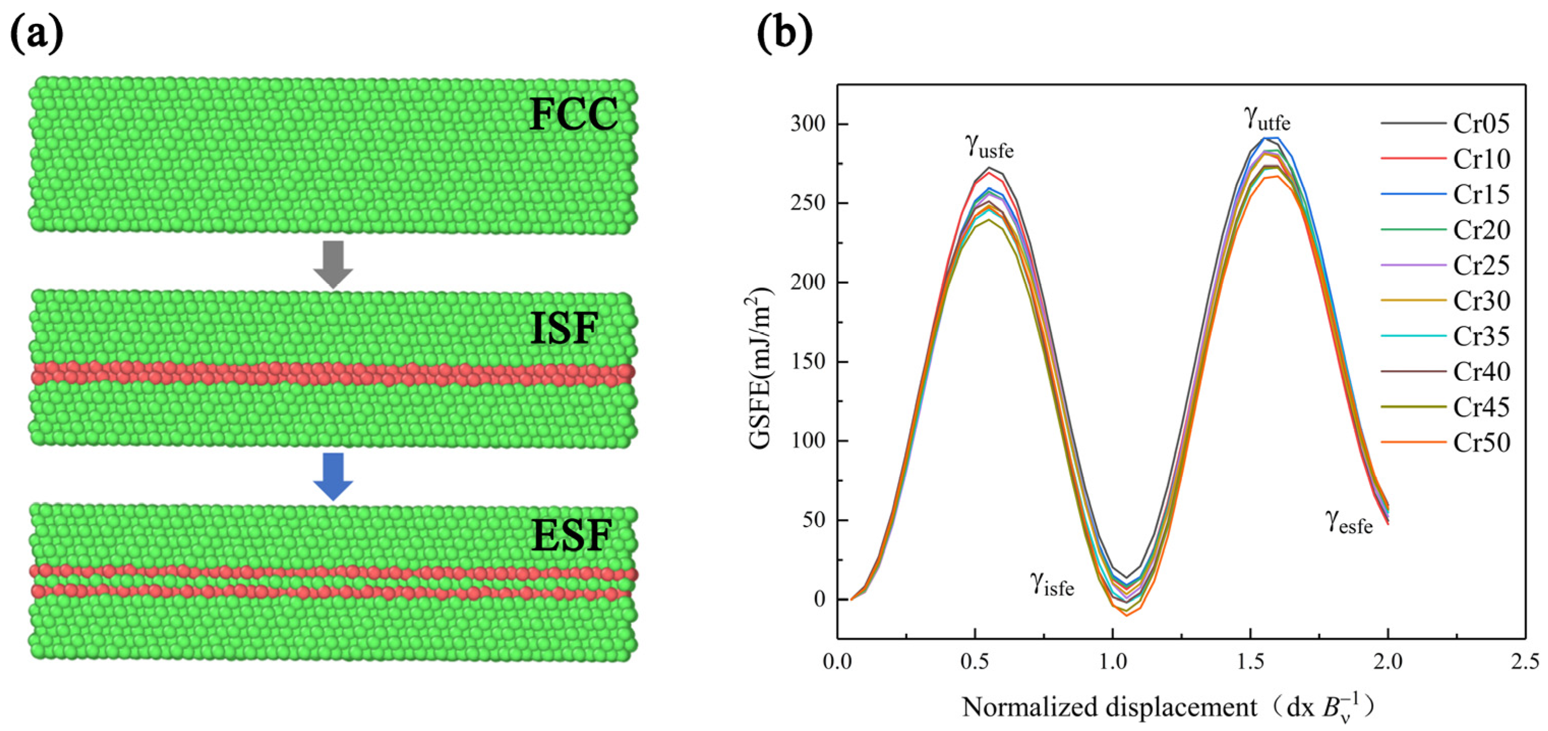
The existing research shows that the mechanical properties and deformation mechanism of HEA are obviously affected by SFE. Moreover, the use of MD can reasonably and effectively calculate the GSFE of alloys. Therefore, this paper referred to the MD simulation method of Chen [29] et al., using the molecular dynamics simulation software LAMMPS to establish the lattice directions x, y, and z, which were in the [11], [111], and [10] directions. Using the modified embedded atom method (MEAM) to calculate the interaction between atoms of HEA [41], periodic boundary conditions were used in the x and y directions, and free boundary conditions were used in the z direction. The model was balanced at 300 K for 0.01 ns. After completing MC simulation to guarantee more stable and real atomic structure, the model was relaxed for 0.05 ns at 300 K NPT, since the dislocations in the FCC were mainly moving in the <112> direction. When calculating the GSFE, we moved the upper part of the model by two units of dislocation length (Bv) in the <112> direction and obtained the GSFE data by calculating the energy difference. Then, the atom replacement command was used to change the model Cr atom content in turn. The GSFE of CoCrxFeMnNi HEA with Cr content between 5–50 at.% was calculated as shown in Figure 1. The GSFE curves show the energy change with plastic deformation in Figure 2 [42,43,44,45]. The first local maximum value γusfe is the lowest energy required for dislocation nucleation, which is called unstable stacking fault energy. First local minimum γisfe is a stable value, called stable SFE, and is also the only SFE data that can be measured in experiments. FCC-structured metals with low stable SFE are prone to deformation twins. Second maximum γutfe is the energy required for sliding on the pre-existing stacking fault, that is, the unstable twin SFE. The larger the specific value of the γusfe to the γutfe, the easier the material is to produce deformation twins. Second local minimum γesfe is the intrinsic SFE. γusfe, γisfe, and γutfe are three important parameters to describe the deformation mechanism of materials.
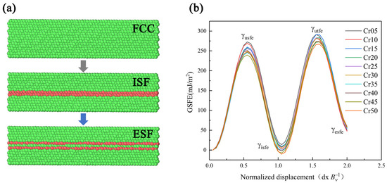
Figure 1.
Simulation diagram (a) and curves of HEAs (b) of generalized stacking fault energy.
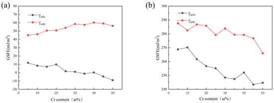
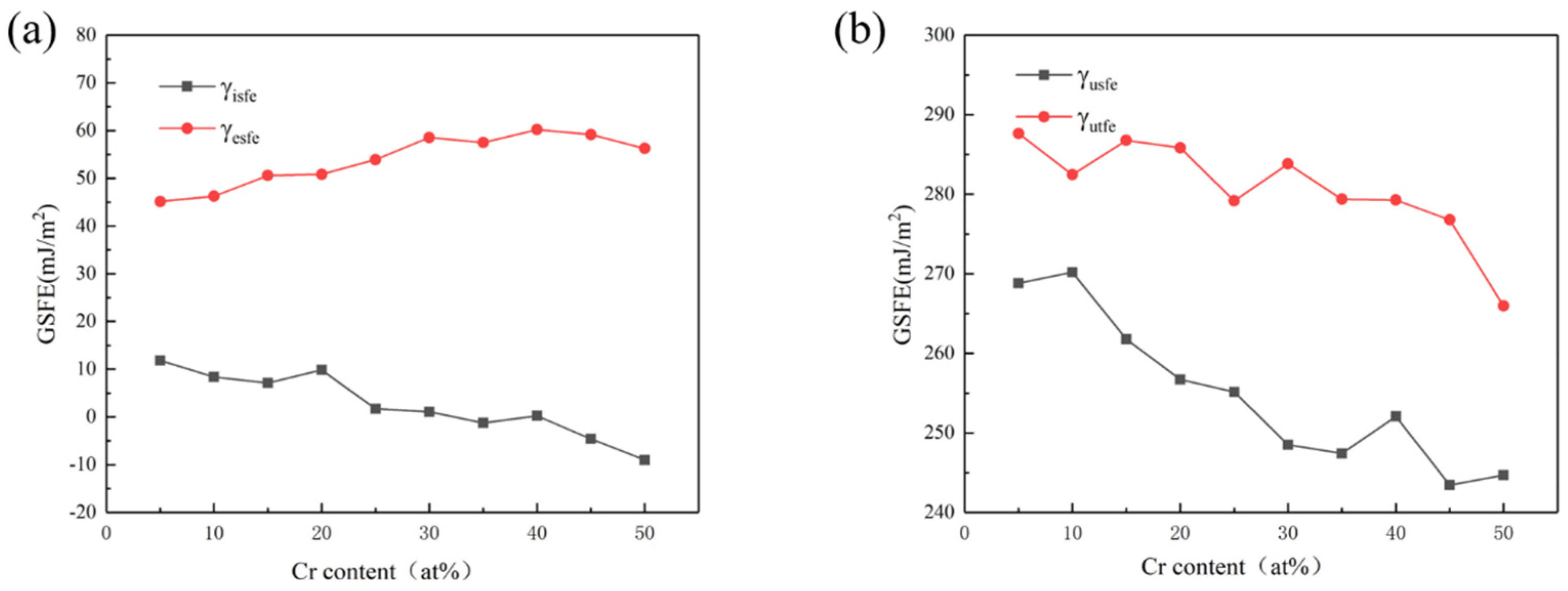
Figure 2.
Curves of the γisfe, γesfe (a), and γusfe, γutfe (b) as the content of Cr element is varied.
The curves in Figure 2 show that with the increase in Cr content, γusfe, γisfe, and γutfe showed a downward trend as a whole. The γesfe showed an opposite increasing trend, and these results are basically consistent with those in the literature [28,29]. Since the lower γusfe is, the easier the dislocation nucleation is, the plasticity of the material will be better. The decrease in γisfe and γutfe indicates that, with the rise of Cr content, the strain strengthening ability of the material was improved due to more deformation twins. When Cr content reached 40%, γusfe showed a fluctuation trend of first increasing and then decreasing, which may be related to the change in component content reaching the transition node from HEA to medium-entropy alloy. Therefore, increasing the Cr content of the HEA in this system can make the material more prone to twin deformation, as well as improve dislocation density, strain hardening rate, and toughness [46,47].
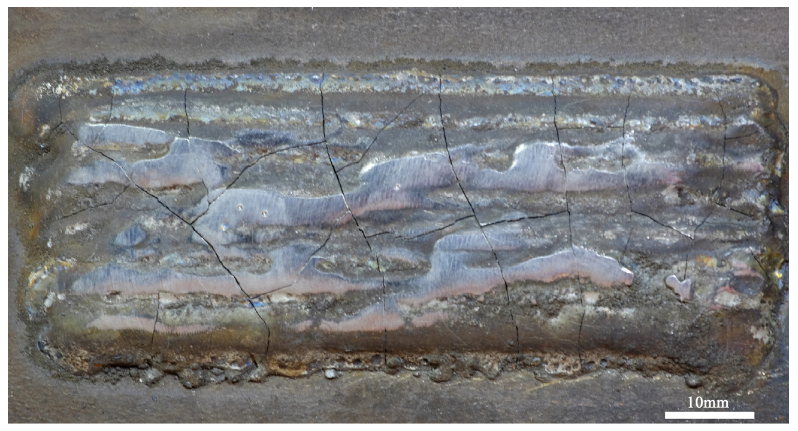
Therefore, in order to select alloy components with better cavitation resistance based on the CoCrFeMnNi with equal atomic ratio, several CoCrxFeMnNi HEAs with increased Cr content were selected in this paper. Combined with the above calculation results, the CoCrxFeMnNi (x: molar ratio, x = 20, 25, 30, and 35, denoted as Cr20, Cr25, Cr30, and Cr35 alloys) were selected. We tried the CoCrFeMnNi HEA cladding experiment with Cr content of 40%. However, it was found that the alloy with this proportion was not conducive to the stable existence of sosoloids due to the large difference in atomic radius and high mixing melting point. Although the hardness reached 43.2 HRC, the coating was difficult to form and had serious cracks in the existing plasma cladding process window (Figure 3). Therefore, this paper only discusses CoCrxFeMnNi HEA with Cr content of 20~35%.
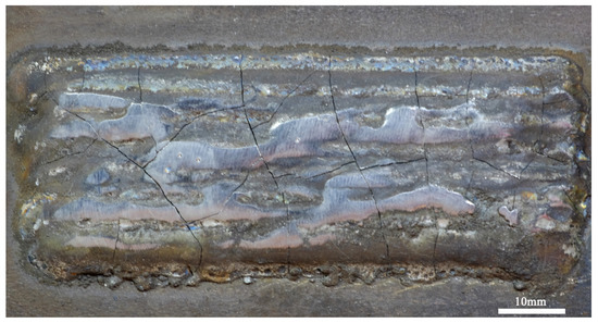
Figure 3.
Macroscopic surface morphology of HEA coating with 40% Cr content.
2.2. Coating Preparation
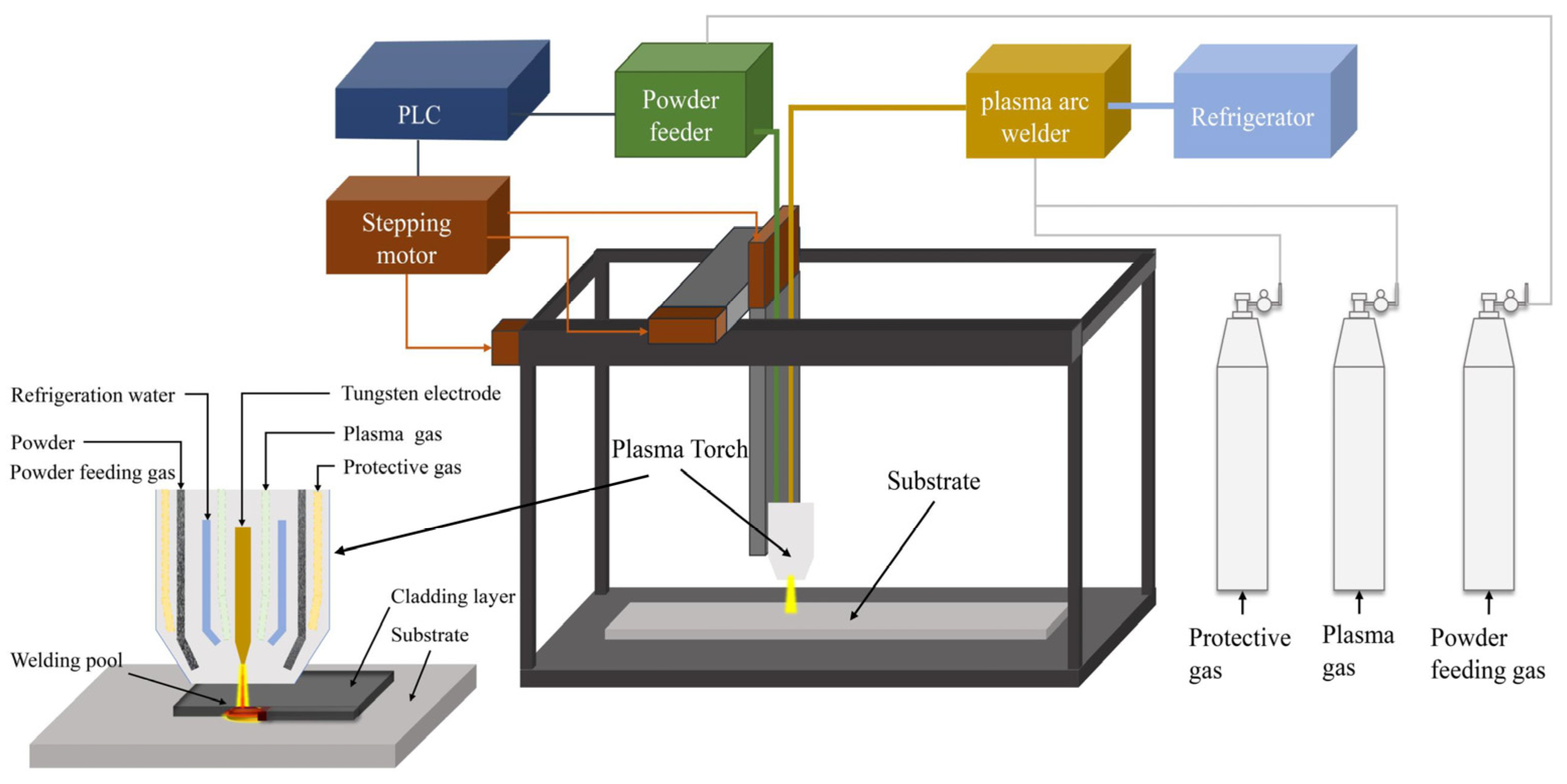
Co, Fe, Mn, Ni (purity ≥ 99.9%), and Cr (purity ≥ 99.5%) metal powders with a particle size of 150 um were used as crude materials and mixed by ball milling in accordance with the set proportion. The mass ratio of the ball to material was 3:1, and the rotating speed was 20 r/min. The mixed powder was milled in argon atmosphere for 30 min. After the mixed powder was dried in a vacuum at 120 °C for 6 h, the coatings were prepared on 0Cr13Ni5Mo stainless steel using the plasma cladding device shown in Figure 4. LHM-500 plasma arc welding machine was used to conduct single-layer and multichannel cladding by synchronous powder feeding. High-purity argon was selected as the shielding gas and powder feeding gas source. The test parameters of the cladding process are shown in Table 2. These HEA coatings were prepared into 20 mm × 20 mm × 20 mm block samples by milling, wire cutting, grinding, and polishing.
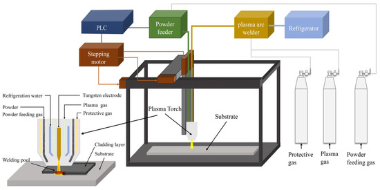
Figure 4.
Schematic diagram of ultrasonic plasma cladding equipment.

Table 2.
Processing parameters in plasma cladding.
2.3. Microstructural and Mechanical Characterization
The polished and cleaned samples were corroded with aqua regia (HC1:HNO3 = 3:1), and then the metallographic structure was observed under a metallographic microscope (Axio Scope A1). Energy-dispersive spectrometer (EDS) and X-ray diffractometer (XRD) were used to analyze the chemical composition and phases of these HEAs. The digital microhardness tester (H-300) was used to measure the hardness of the coating before and after cavitation erosion. Five points were selected in each test area of the sample for measurement, and the average value was taken. The test load was 100 g, and the loading time was 15 s.
2.4. Ultrasonic Cavitation Testing
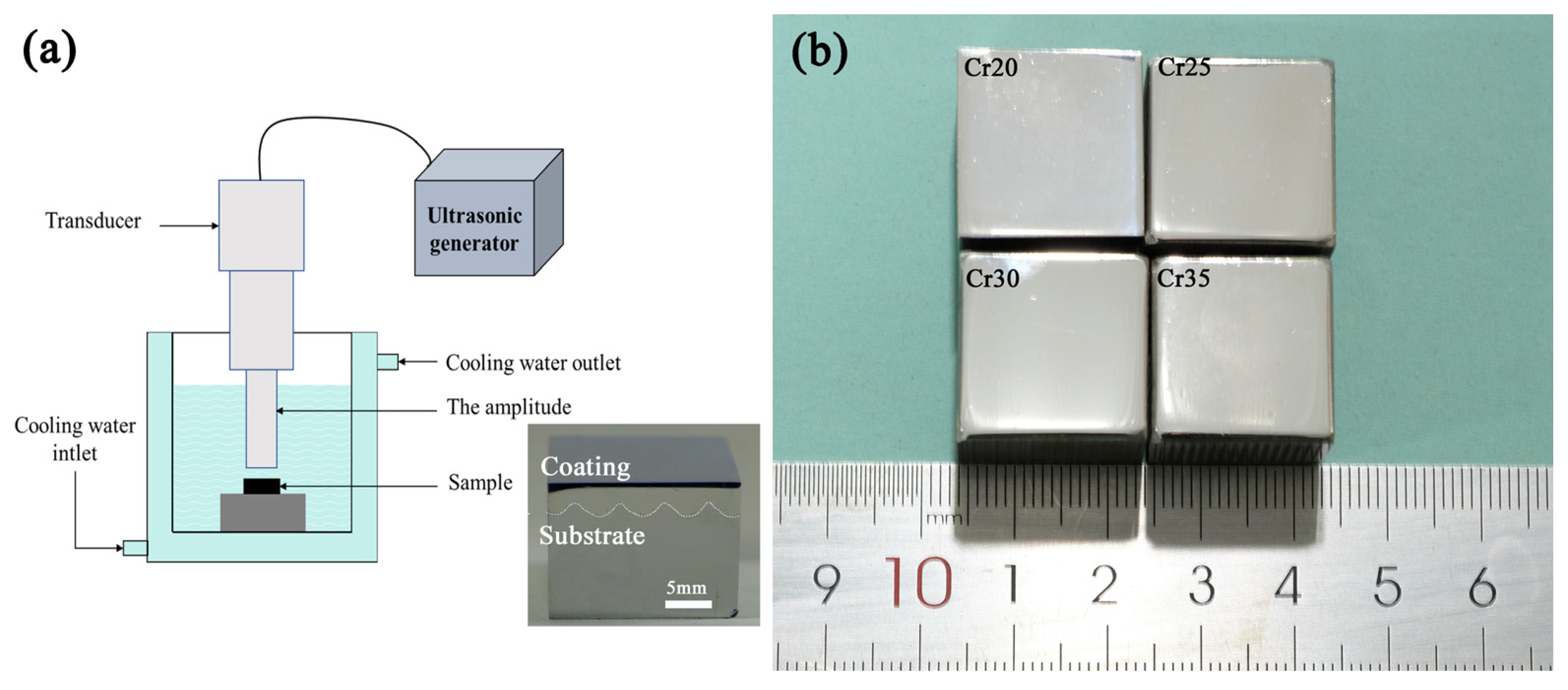
Ultrasonic cavitation tests were carried out using equipment conforming to ASTM G32-10 standard. The samples were fixed at the position 0.5 mm away from the end face of the vibrating head by the fixture. The vibrating tip was immersed in the test medium for 10 mm. The samples were tested for cavitation erosion in distilled water at 25 ± 1 °C for 20 h, and the test medium was cooled by a refrigerator. The working frequency of the vibrating head was 20 ± 0.5 kHz, and the amplitude was 40 μm peak to peak. A detailed description of the cavitation test device is shown in Figure 5a. The vibrating head was 20 mm in diameter. The surface of the cuboid specimens (20 mm× 20 mm × 16 mm) were polished by 2.5 mm diamond before cavitation erosion tests were performed. The coating of the sample has no cracks. As shown in Figure 5b, the surface condition of each sample is consistent. It is reasonable to compare the cavitation erosion performance of samples after the same treatment method. A balance with an accuracy of 0.01 mg was used to measure the mass loss (ML) every 1 h during the 20 h cavitation process of the sample. After the mass loss was converted into volume loss, the cavitation erosion performance of the tested sample was studied by analyzing the cavitation characteristics such as cumulative volume loss (CVL), cumulative volume loss rate (CVR), and cavitation incubation period [48]. Meanwhile, JSM-IT00 scanning electron microscope (SEM) was used to analyze the morphology after cavitation test to analyze the cavitation damage mechanism.
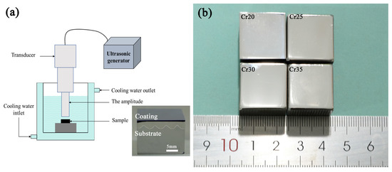
Figure 5.
Schematic diagram of ultrasonic cavitation tests equipment (a) and macrosurface morphology of coatings (b).
2.5. Electrochemical Testing
In addition to mechanical damage, the actual cavitation erosion process is often accompanied by corrosion. Therefore, in the study of the change in high-entropy alloy properties with elements, the corrosion performance needs to be measured as an inspection parameter [14,15]. Therefore, 3.5 wt.%NaCl solution was selected to conduct electrochemical tests to explore the effect of the proportion change in Cr element on the corrosion performance of this kind of HEA.
The sample was welded with copper wire, sealed, and cured with epoxy resin. After the surface treatment of the working surface reaches the specified requirements, the rest was sealed with epoxy resin. Finally, ultrasonic cleaning with alcohol for 20 min, rinsing with deionized water, and drying for standby were carried out. The saturated calomel electrode was used as the reference electrode and the graphite sheet as the auxiliary electrode. The tested sample was the working electrode of the three-electrode system. The dynamic potential polarization curves of the HEA coating and the 0Cr13Ni5Mo steel were studied at room temperature using an electrochemical workstation (CHI660D) in 3.5% NaCl solution. The scanning potential range of 0Cr13Ni5Mo steel and HEA coatings in 3.5% NaCl solution was −0.8~0.2 V, and the scanning rate was 0.33 mV/s.
3. Results and Discussion
3.1. Microstructure and Mechanical Properties of CoCrxFeMnNi HEA Coatings
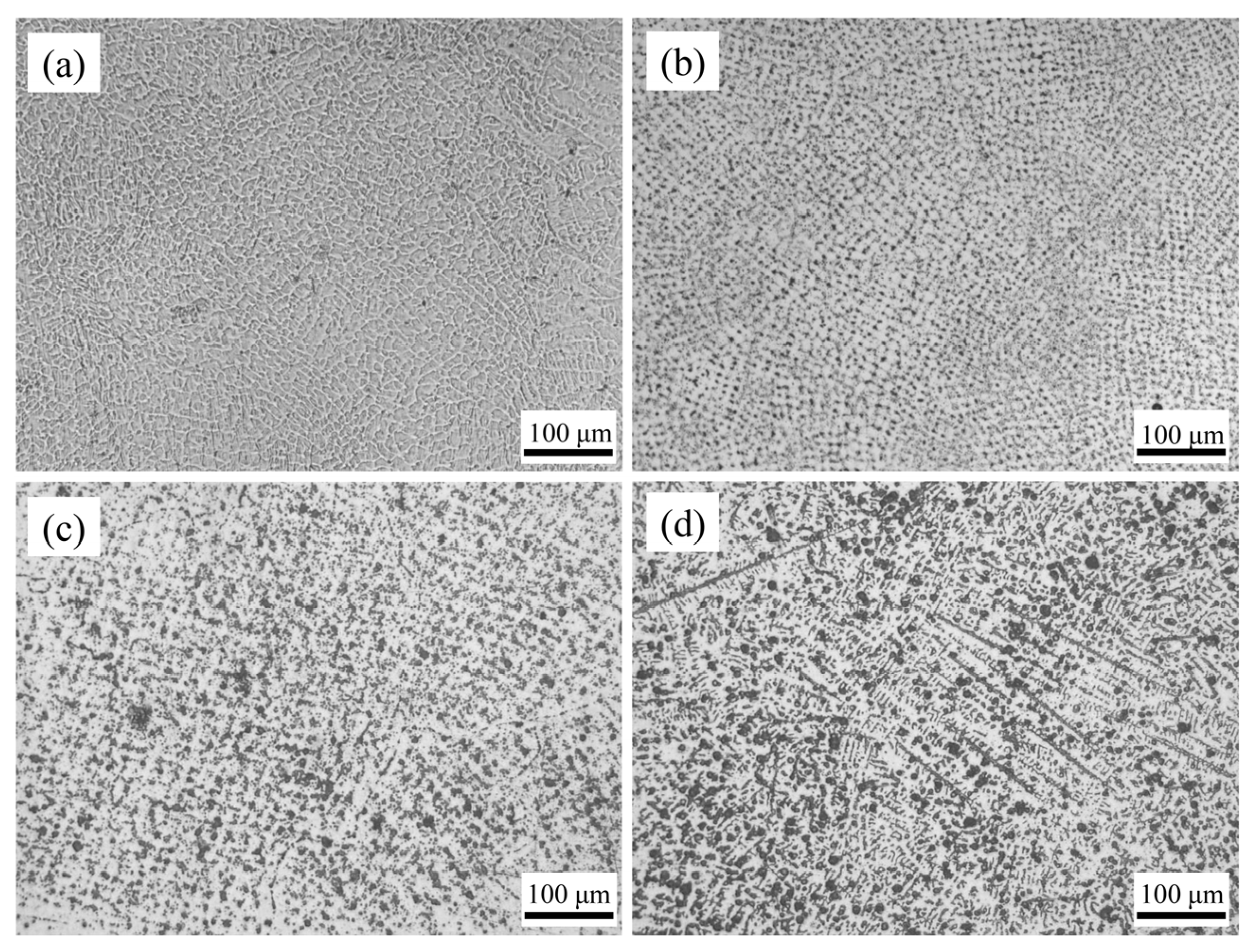
The microstructure of the HEA coating weld bead is shown in Figure 6. The structure of Cr20 was uniform and regular. Because it was a coating prepared by multipass lapping, the lapping part of the weld bead edge will be heated again because of the later cladding. A small amount of crystalline grain in the cladding layer will be remelted and solidified. Therefore, the structure in this area grows up to a certain extent. The grains became more uniform as the distance from the center of the molten pool decreased. The grains of CoCrxFeMnNi HEA coatings tended to be elongated with the rise of Cr content. When the Cr content increased to Cr35, an obvious acicular dendrite structure was formed. This was mainly due to the high melting point of Cr element. With the cocktail effect of HEA, the melting point of the alloy increased with the rise of Cr content, which made the grains fail to homogenize at the crystallization temperature. Therefore, the rise of Cr content made the microstructure of the coatings gradually change from flat and uniform cellular crystal to fine-needle dendrite.
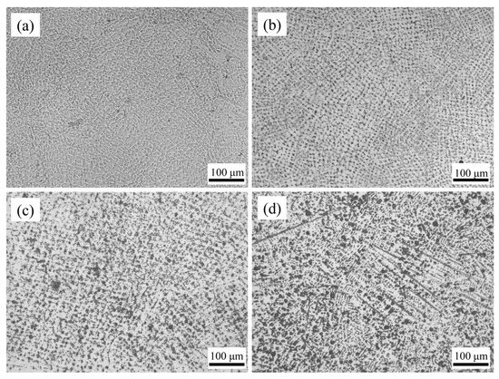
Figure 6.
The surface morphologies of CoCrxFeMnNi HEA coatings: (a) Cr20, (b) Cr25, (c) Cr30, and (d) Cr35.
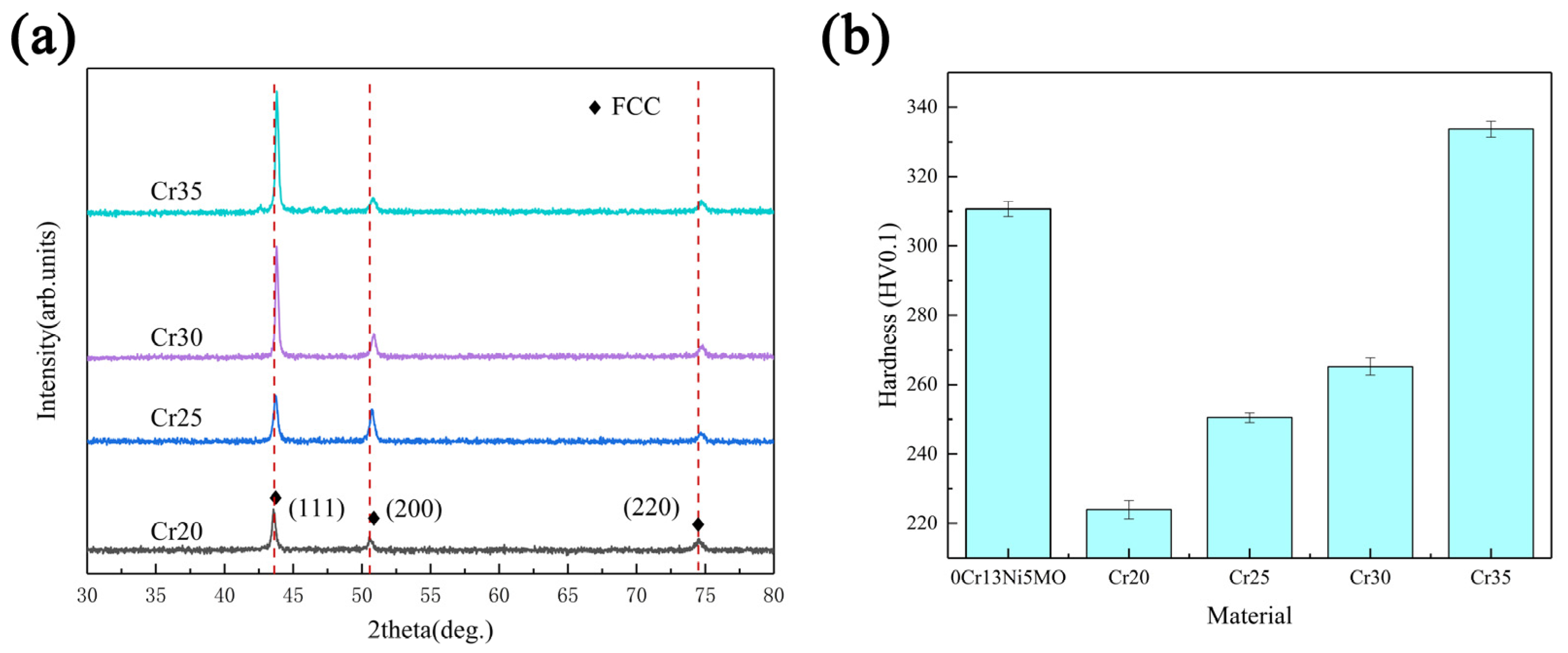
The XRD spectra of each coating of CoCrxFeMnNi HEA showed that FCC solid solution was formed, which is consistent with the phase composition parameters calculated previously (Figure 7a). As the Cr content increased, the grains had a tendency to crystallize in the direction (111). The crystallinity of the peak (111) increased. Additionally, the height of the peak increased. At the same time, the shape and size of the grains changed as well, reducing the width of the diffraction peak. Due to the increase in Cr content, the lattice distortion of high-entropy alloys increased. The diffraction peak shifted [49,50]. The microhardness of the coating also increased significantly with the rise of Cr content, as shown in Figure 7b. Additionally, the microhardness of Cr35 reached 333.7 HV, which was 49.04% higher than the 223.9 HV of Cr20. Cr35 alloy had the largest lattice distortion and the most obvious dendrite morphology. Therefore, compared with the other three kinds of HEAs, Cr35 alloy had greater strengthening and the largest increase in hardness. In addition, according to the cocktail effect of the HEA, the hardness will increase by increasing the proportion of the Cr element with high hardness. With the rise of Cr content, the shape of grain becomes longer and irregular. The resistance of material deformation and crack propagation increased, which increased the hardness. In the meantime, the SFE of the system was reduced, which made twins easy to form during deformation. The strength and work hardening ability were improved, showing an increase in microhardness.
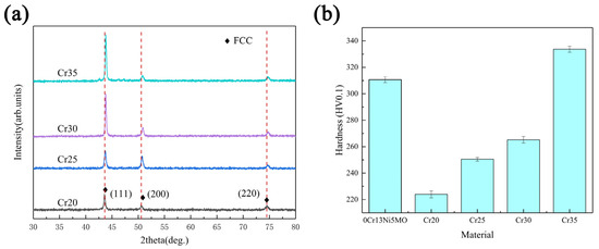
Figure 7.
XRD patterns of the HEA coatings (a) and microhardness of substrate and coatings (b).
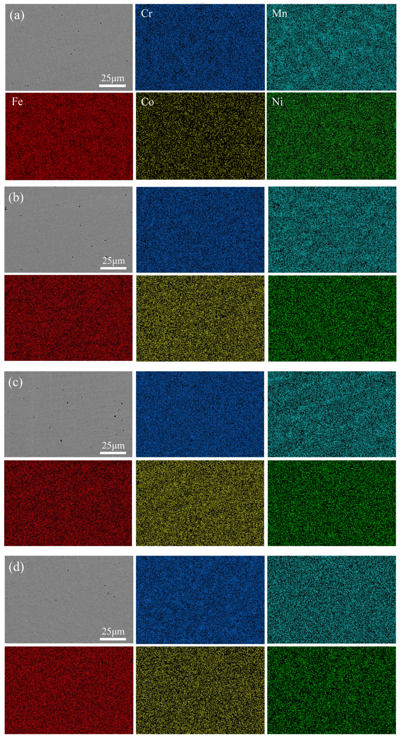
Figure 8 shows the distribution of the five main elements on the surface of four kinds of HEA coatings, which were uniformly distributed and free of segregation. Table 3 presents the content of the element of the EDS mapping of the four coatings. The ratio of Cr to Mn, Co, and Ni basically met the expected setting. However, during the cladding process, the metal powder melted rapidly under high energy and was metallurgical bonded with the base material. Elements diffused between the base material and the coatings. The diffusion of the Fe element increased the proportion of Fe element in the coating, which made the element composition of coatings inevitably deviated from the expectation, as the Fe element generally had little influence on the solid solution phase and microstructure. Additionally, the overall change trend of Cr content remained unchanged [27,51]. Therefore, we can still discuss the effect of Cr element change on the properties of CoCrxFeMnNi HEA in this system.
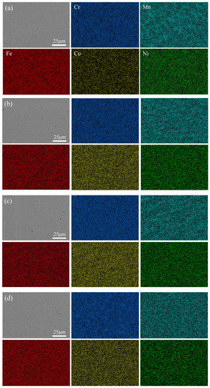
Figure 8.
Elemental EDX maps of CoCrxFeMnNi HEA coatings: (a) Cr20, (b) Cr25, (c) Cr30, and (d) Cr35.

Table 3.
Compositions (At.%) of various regions in CoCrxFeMnNi HEA coatings.
3.2. Cavitation Mechanisms of the CoCrxFeMnNi HEA Coatings
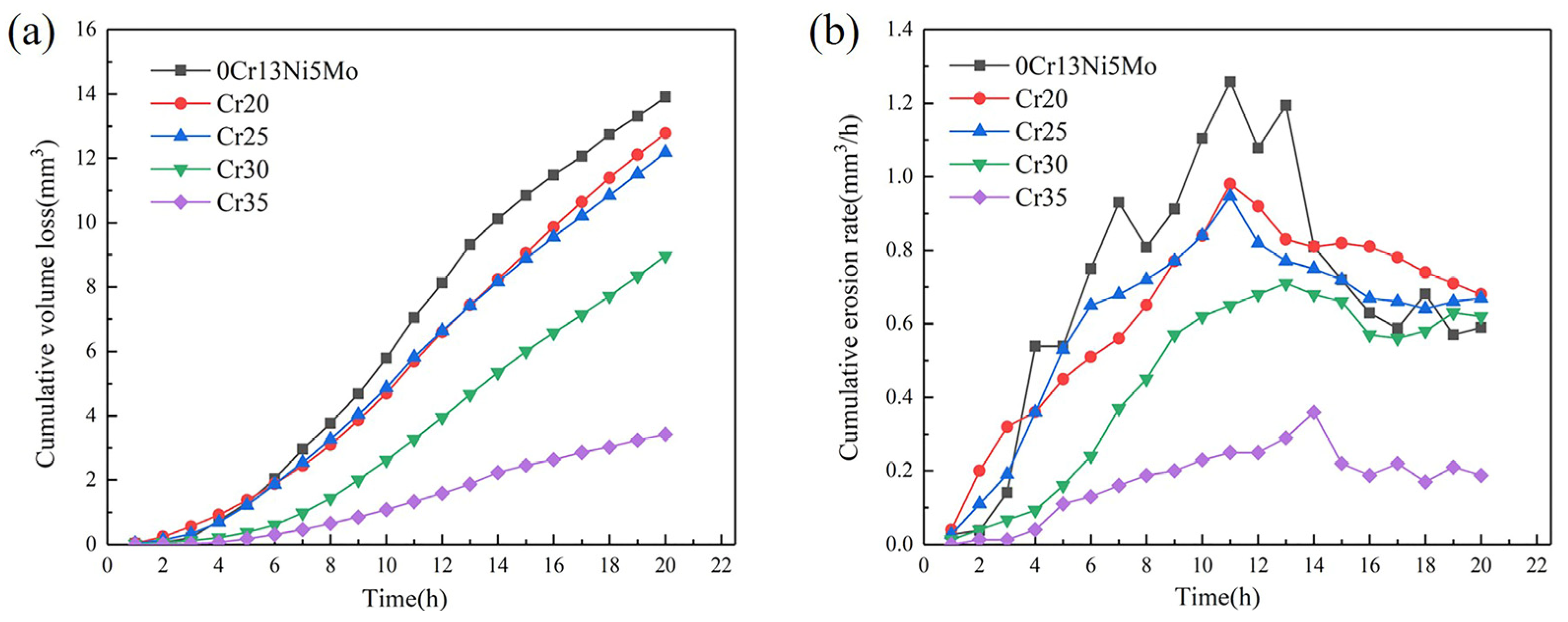
The CVL curves and CER curves of the four HEA coatings and the base material 0Cr13Ni5Mo stainless steel are shown in Figure 9. After 20 h of cavitation, the CVL of 0Cr13Ni5Mo stainless steel was 13.91 mm3. The CVL of Cr20 and Cr25 HEA coatings were comparable: 12.78 mm3 and 12.18 mm3, respectively. However, the increase in Cr content made CVL gradually decrease. The change slope of the CVL curves of the coating also gradually decreased. The volume loss of Cr35 coating after 20 h cavitation erosion is 3.43 mm3, which was only 26.84% of the steel.
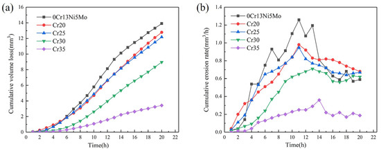
Figure 9.
CVL curves (a) and CVR curves (b) as a function of cavitation duration of CoCrxFeMnNi HEA coatings and 06Cr13Ni5Mo steel.
It can be found out from Figure 9b of the CER curves that the cavitation process of HEA coatings and 0Cr13Ni5Mo stainless steel presented four stages, as follows: the incubation period, the rising period, the decay period, and the stable period of cavitation erosion [52]. The cavitation erosion of 0Cr13Ni5Mo steel entered the development stage after about a 2 h incubation period. The CE rate in this stage rose sharply. After 16 h, it developed into a stable CE stage, and its cavitation erosion rate changed between 0.60~0.68 mm3/h. Compared with 0Cr13Ni5Mo stainless steel, the HEA coatings changed more gently in their rate of rise. The duration of incubation period and peak cavitation rate increase with the change in Cr content. The CER of the HEA coatings Cr30 and Cr35 were obviously lower than that of other groups of samples. After about 4 h of incubation period for CE, there was a marked difference in the CE development process between the two groups. The CER of the Cr30 coating rose rapidly and reached its peak value at 13 h. The CER of the Cr35 coating was relatively slow. Although the Cr35 also experienced an ascending period to reach its peak value and decrease into a stable period, its peak value was only 0.36 mm3/h. It was 28.57% of the peak rate of base stainless steel, 1.26 mm3/h.
According to the analysis of the hardness data in the previous article, it can be made out that the hardness of the CoCrxFeMnNi HEAs had a strong correlation with the CR. Additionally, the CR gradually improved with the increase in hardness. The hardness of the base material 0Cr13Ni5Mo steel was obviously higher than that of the three coatings, except Cr35. The CR of 0Cr13Ni5Mo was still inferior to that of these HEA coatings. It can be seen that hardness cannot be used as a single criterion for cavitation resistance. Different types of materials and deformation mechanisms had a huge influence on the cavitation resistance mechanism. Therefore, the next step was to analyze the cavitation damage behavior of samples.
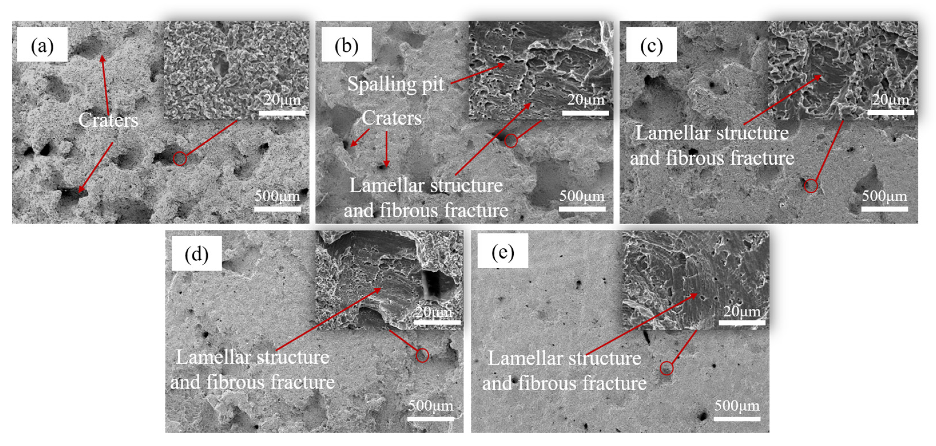
The surface morphologies of the five materials after 20 h of CE, are shown in Figure 10. Among them, the pore cracks and other damages of 0Cr13Ni5Mo martensitic stainless steel were relatively dense. The surface of 0Cr13Ni5Mo had deeper peeling pits and more cavitation erosion holes compared with coatings. The surface of 0Cr13Ni5Mo presented a loose and porous morphology. The fracture type was analyzed by enlarging the peeling area. It was found that the peeling form of stainless steel has both ductile fracture and brittle fracture. The surface presented obvious plastic deformation and cracks. The 0Cr13Ni5Mo was divided into small pieces of material, and the surface was relatively rough. Although the damage morphology was similar, the surface of the HEA coatings were relatively flat. Macroscopically, there were fewer large-area cavitation pits than 0Cr13Ni5Mo martensitic stainless steel. As the proportion of Cr element increased, the damage degree of the coatings became weaker, until there was no large-area peeling trace on the Cr35 surface. The SEM images of the scanning electron microscope showed that the fracture damage mechanisms of the four HEA coatings were similar. The morphology of the peeled holes was basically as shown in the enlarged area in Fig 10, which was an obvious lamellar structure and fibrous fracture. Therefore, the damage mode of HEA coatings was mainly ductile fracture.
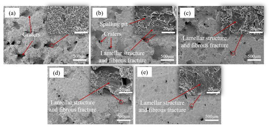
Figure 10.
The surface morphologies of (a) 0Cr13Ni5Mo steel, (b) Cr20, (c) Cr25, (d) Cr25, and (e) Cr35 after CE for 20 h in distilled water.
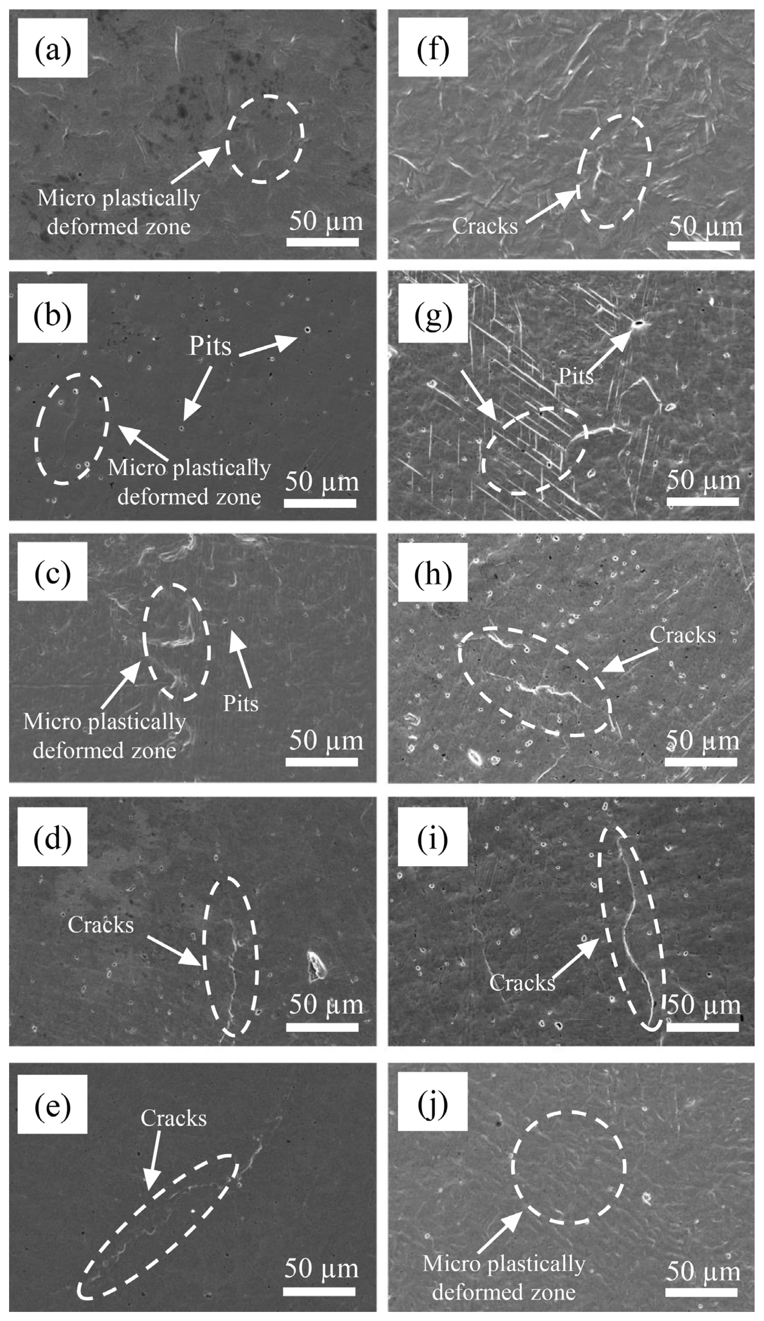
In order to study the damage mechanism at the initial stage of CE, the surface morphology of the base material 0Cr13Ni5Mo martensitic stainless steel and four kinds of HEA coatings were observed at the initial stage of CE. As shown in Figure 11, after 0.5 h of CE, the surface of 0Cr13Ni5Mo steel had slight plastic deformation, showing shallow pits and wrinkles. The surface morphologies of the HEA coatings were relatively flat, with only a few deformation wrinkles and holes, because vulnerable areas in the coating will directly peel off and form small holes under the impact of a jet during CE. With the rise of Cr content, the deformation degree of the sample surface became smaller and smaller. After 1 h, under the continuous bombardment of CE, the surface deformation of the HEAs and 0Cr13Ni5Mo steel was gradually serious. The grains extrude each other at the junction and bulge and distort. The deformation of the Cr20 HEA coating was more regular, with parallel slip bands. Similarly, several other HEA coatings also had stacked slip lines on the surface. The distribution was relatively sparse compared with Cr20, and the shape was more irregular. As the proportion of Cr element increased, the microstructure distribution on the coating surface became more and more uneven; the grain boundary becomes more irregular. The slip line became bent due to excessive deformation at the place where the stress was concentrated. At the same time, the finer the grain, the more tortuous the grain boundary. The crack propagation resistance along the grain boundary was greater. More energy needed to be absorbed during fracture. Therefore, the coating with higher Cr content showed higher toughness. Among them, Cr35 showed an obvious tendency of damage along the grain boundary. Plastic deformation accumulated at the crystal boundary to form a slip band, which then became cracked and continued to expand to a certain extent, causing damage and destruction [53,54].
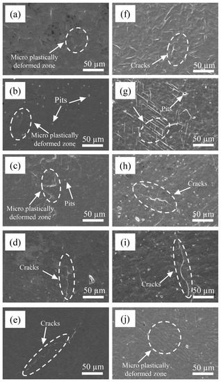
Figure 11.
The surface morphologies of Cr20 (b,g), Cr25 (c,h), Cr20 (d,i), Cr20 (e,j), and 0Cr13Ni5Mo steel (a,f) after CE tests for (a–e) 0.5 h and (f–j) 1 h in distilled water.
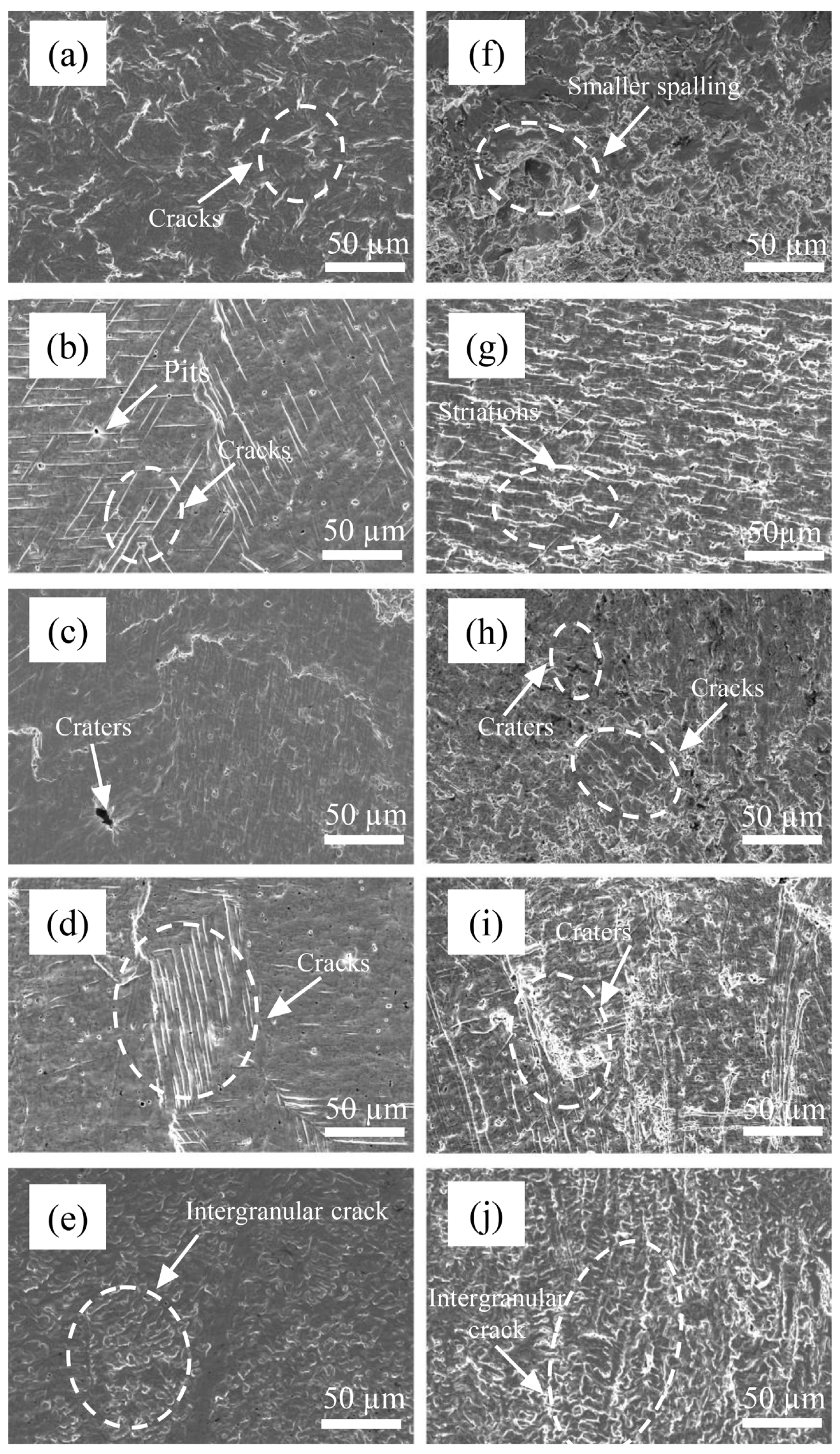
At 2 h, the plastic deformation of 0Cr13Ni5Mo martensitic stainless steel further expanded. The stress became more concentrated. The cracks formed and continued to expand, and obvious damage spalling occurred at 3 h, as shown in Figure 12. At 2 h, more obvious parallel slip bands appeared on the surface of the coatings. The directions of each slip band were different due to the different grain directions. At the same time, with the rise of proportion of Cr, the grains of the HEA coatings became thinner and longer, and the distribution was uneven. Therefore, the distribution of parallel slip bands was also obviously different and was along the grain direction. The growth of cracks tended to occur at the grain boundary due to stress accumulation. Therefore, the coating surface with high Cr content had more irregular damage traces. At the same time, some slip lines stopped expanding at the holes on the material surface. The accumulated energy was released at the holes. After 3 h, the plastic deformation reached a certain limit. Some grains were completely destroyed. Additionally, the barrier against cavitation erosion of the structure disappeared. The cracks gradually nucleated with a large number of dislocation slips, cross slips, and dislocation accumulations. The crack extension and hole expansion led to a large area of material falling off. The accumulation of stress concentration and plastic deformation led to the initiation of cracks at the grain boundary. It can be observed in the figure that the crack extended at the grain boundary. When the damage of two adjacent grain boundaries was gradually extended and connected together, large pieces of material peeled off. The material peeling mechanism made the peeling boundary regular and flat.
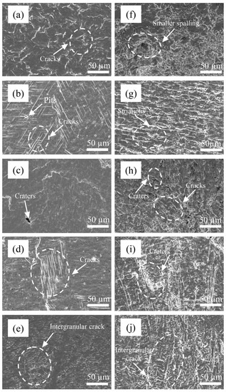
Figure 12.
The surface morphologies of Cr20 (b,g), Cr25 (c,h), Cr20 (d,i), Cr20 (e,j), and 0Cr13Ni5Mo steel (a,f) after CE tests for (a–e) 2 h (f–j) 3 h in distilled water.
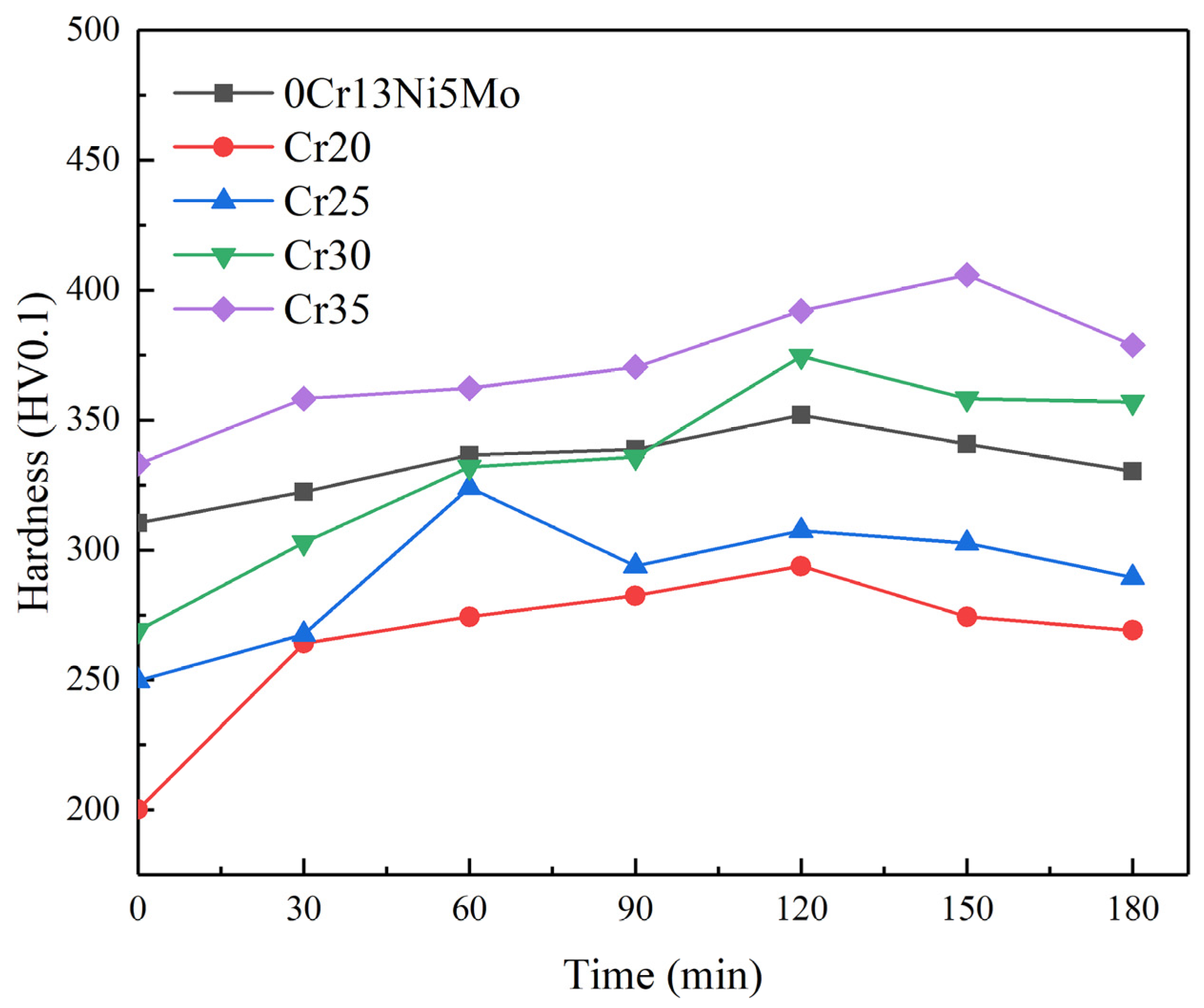
The degree and depth of deformation and the subsequent fracture mode of materials fundamentally determine the ability of materials to absorb cavitation damage energy [55,56]. The change in hardness before and after cavitation is one of the indicators reflecting the deformation strengthening ability of materials. The small-sized pits and cracks of HEA at the initial stage of CE were affected by its work hardening behavior. The work hardening ability of HEAs is affected by element composition [57,58]. In order to further explore the change in hardness of HEA and 0Cr13Ni5Mo steel under CE, the microhardness of the sample after different CE durations is shown in Figure 13. The hardness of each material was increased. However, compared with 13.37% of the base material martensitic stainless steel, the hardness of the Cr20 HEA coating was increased to 46.8% of the original hardness. This was why the CR of HEA was still higher than that of 0Cr13Ni5Mo martensitic stainless steel when the initial hardness difference was large. Materials with lower SFE can make dislocation movement more difficult. This leads to more uniform slip distribution so that the stress increase required for material deformation is achieved. With the increase in Cr ratio, the uniform slip distribution became less, and the hardness change in the coating became relatively gentle. In addition, the microstructure, deformation mode, and strain-rate sensitivity of materials directly influence the CR of materials, which determines the dissipation mode of materials for cavitation energy impact. The FCC structure of the HEA coatings was not sensitive to the strain rate. Therefore, the increase in flow stress required for plastic deformation is also the reason for enhancing the CER of HEA coating.
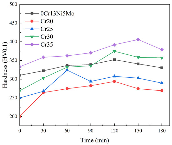
Figure 13.
The hardness of 0Cr13Ni5Mo steel and the CoCrxFeMnNi HEA coatings after CE tests in distilled water.
3.3. Corrosion Behavior of Coatings
The process of cavitation erosion in distilled water was mainly mechanical. In practical industrial applications, various metal materials and machinery subject to cavitation erosion often operate and work in various corrosive media and fluids. For example, for ships sailing in the ocean, their propeller blades are not only troubled by cavitation erosion but also greatly damaged by seawater corrosion. In these corrosive fluids, corrosion is a feature in the cavitation process, and the corrosion resistance of materials will greatly affect their CR. The CR of HEA is significantly affected by element content [59,60,61].
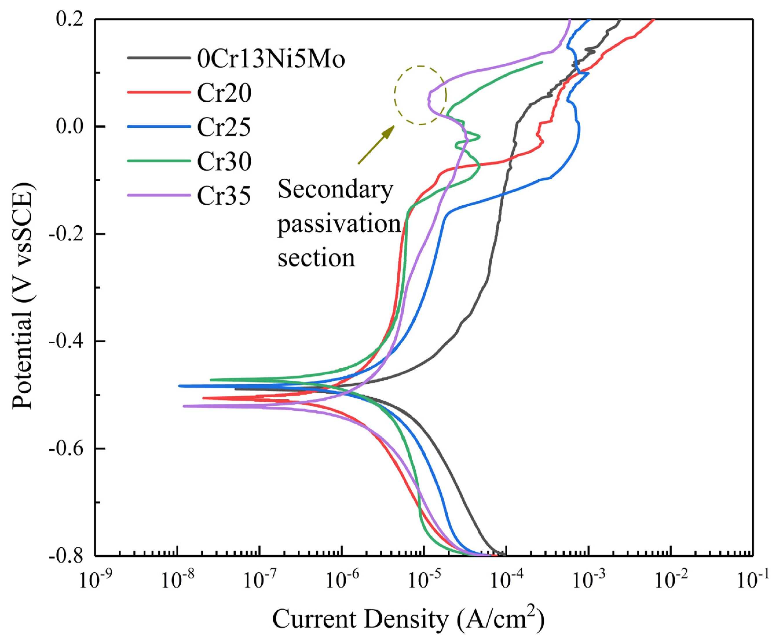
In this paper, the electrochemical properties of the 0Cr13Ni5Mo steel and HEA coating were tested. The polarization curve of 0Cr13Ni5Mo steel and four kinds of HEA coatings in 3.5% NaCl solution are shown in Figure 14. The electrochemical parameters, including corrosion potential (Ecorr), corrosion current density (Icorr), and pitting potential (Epit), were obtained by the Tafel extrapolation method (Table 4) according to the principle of electrochemical corrosion. Ecorr is a thermodynamic parameter to measure the corrosion tendency of the alloy. If Ecorr is positive and the positive value is higher, the corrosion tendency of the alloy is smaller. If Ecoor is negative and the negative value is higher, the corrosion tendency of the alloy is greater. The Icorr is a dynamic parameter which can directly explain the corrosion rate of alloys. Therefore, Icorr is an important indicator to judge the corrosion rate of alloy. The smaller the Icorr, the lower the corrosion rate of alloys. In addition, materials with passivation have good corrosion resistance. The data in the table show that the Icorr of the four groups of HEA coatings was less than that of 0Cr13Ni5Mo martensitic stainless steel. The corrosion rate of the HEA coatings was less than that of the base material. Therefore, the corrosion resistance of the four groups of HEA coatings decreased first and then increased with the change in Cr content, showing a trend of Cr20 > Cr35 > Cr30 > Cr25. In addition, it can be seen from the polarization curve that spontaneous passivation zone appears in the HEA coatings of Cr20, Cr25, and Cr30. Additionally, the figure shows that the HEA coatings had obvious secondary passivation. This was due to areas where the coatings’ surfaces were not tightly bonded, such as pores and other defects, around which were first corrosion and dissolution. Then, the remaining HEA matrix had good corrosion resistance, which reduced the current density and kept it for a period of time. The coatings were more effective in preventing corrosion point expansion.
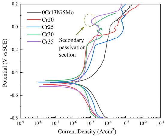
Figure 14.
Polarization plots of the 0Cr13Ni5Mo steel and CoCrxFeMnNi HEA coatings in 3.5% NaCl solution (open to air).

Table 4.
The electrochemical parameters of the HEA coatings and 0Cr13Ni5Mo.
4. Conclusions
More excellent strength, corrosion resistance, and other characteristics make HEAs have a very broad prospect in preparing cavitation-resistant coatings. Based on the characteristics of materials, it is scientific and feasible to design HEAs with better properties by adjusting the proportion of elements. CoCrxFeMnNi (x = 20, 25, 30, and 35) HEA coatings were successfully prepared by plasma cladding, and the damage morphology of HEA coatings was analyzed. The mechanical behavior, CR, and corrosion resistance of these coatings were studied and compared with the corrosion resistance of 0Cr13Ni5Mo steel. The main conclusions are as follows:
- Cr20, Cr25, Cr25, and Cr35 were single-phase FCC HEAs. As the Cr content increased, the grains had a tendency to crystallize in the direction (111). The lattice distortion of high-entropy alloys increased. The diffraction peak shifted. With the rise of Cr content, the microstructure of the coatings changed from flat and uniform to fine dendrites, and the hardness also increased. Compared with the other CoCrxFeMnNi HEAs, Cr35 had the most obvious structural change and the largest lattice distortion. The hardness of Cr35 coating reached 333.7 HV.
- The rise of Cr content enhanced the CR of CoCrxFeMnNi HEA coatings. The CVL of 20 h cavitation erosion of Cr35 was only 26.84% of that of 0Cr13Ni5Mo martensitic stainless steel, and the peak cavitation erosion rate was 28.57% of that of the base stainless steel.
- Because the SFE of the CoCrxFeMnNi HEA coatings decreased with the rise of Cr content, it was easier to form twins. The plastic toughness and work hardening ability were improved. Cavitation failure of CoCrxFeMnNi was a process from slip accumulation to crack generation and propagation, which led to fibrous ductile fracture. With the transformation from grains to dendrites, under the influence of irregular grain boundaries on the slip, the damage changed from a uniform regular slip to a mode of spreading along the grain boundaries.
- The electrochemical Icorrof CoCrxFeMnNi HEA coatings was lower than 0Cr13Ni5Mo steel, that is, the corrosion resistance was better than that of the base material. There was a passivation zone, indicating that the HEA coatings had a stable passivation film. The polarization curve of the Cr35 coating had a secondary passivation interval, which can effectively prevent the corrosion point from expanding.
Author Contributions
Conceptualization, X.X. and D.Y.; methodology, N.M. and D.Y.; validation, K.Z.(Keke Zhang); formal analysis, K.Z. (Kaige Zhang); investigation, K.Z. (Keke Zhang); resources, K.Z. (Kaige Zhang), B.W. and M.L.; data curation, K.Z. (Kaige Zhang), B.W., and M.L.; writing—original draft preparation, K.Z. (Kaige Zhang); writing—review and editing, D.Y.; visualization, K.Z. (Kaige Zhang); supervision, D.Y.; project administration, D.Y.; funding acquisition, D.Y. All authors have read and agreed to the published version of the manuscript.
Funding
This research was supported by the National Natural Science Foundation of China (grant no. U1904185).
Institutional Review Board Statement
Not applicable.
Informed Consent Statement
Not applicable.
Data Availability Statement
The data that support the findings of this study are available from the corresponding author upon reasonable request.
Acknowledgments
This work has been funded by the National Natural Science Foundation of China grant: no. U1904185 and Foundation for University Key Teacher by Henan Province (2020).
Conflicts of Interest
The authors declare no conflict of interest.
References
- Brijkishore; Khare, R.; Prasad, V. Prediction of cavitation and its mitigation techniques in hydraulic turbines—A review. Ocean Eng. 2021, 221, 108512. [Google Scholar] [CrossRef]
- Reuter, F.; Ohl, C.-D. Nonspherical Collapse of Single Bubbles Near Boundaries and in Confined Spaces. In Cavitation and Bubble Dynamics; Koukouvinis, P., Gavaises, M., Eds.; Academic Press: Cambridge, MA, USA, 2021. [Google Scholar]
- Sreedhar, B.K.; Albert, S.K.; Pandit, A.B. Cavitation damage: Theory and measurements—A review. Wear 2017, 372–373, 177–196. [Google Scholar] [CrossRef]
- Krella, A.K.; Czyżniewski, A.; Gilewicz, A.; Krupa, A. Cavitation erosion of CrN/CrCN multilayer coating. Wear 2017, 386-387, 80–89. [Google Scholar] [CrossRef]
- Harrison, M. An Experimental Study of Single Bubble Cavitation Noise. J. Acoust. Soc. Am. 1952, 24, 454. [Google Scholar] [CrossRef]
- Ye, L.; Zhu, X.; He, Y.; Wei, X. Ultrasonic cavitation damage characteristics of materials and a prediction model of cavitation impact load based on size effect. Ultrason. Sonochem. 2020, 66, 105115. [Google Scholar] [CrossRef]
- Richman, R.H.; McNaughton, W.P. Correlation of cavitation erosion behavior with mechanical properties of metals. Wear 1990, 140, 63–82. [Google Scholar] [CrossRef]
- Zhang, X.-F.; Fang, L. The effect of stacking fault energy on the cavitation erosion resistance of α-phase aluminum bronzes. Wear 2002, 253, 1105–1110. [Google Scholar] [CrossRef]
- Rajendrachari, S. An Overview of High-Entropy Alloys Prepared by Mechanical Alloying Followed by the Characterization of Their Microstructure and Various Properties. Alloys 2022, 1, 116–134. [Google Scholar] [CrossRef]
- Rajendrachari, S.; Adimule, V.; Gulen, M.; Khosravi, F.; Somashekharappa, K.K. Synthesis and Characterization of High Entropy Alloy 23Fe-21Cr-18Ni-20Ti-18Mn for Electrochemical Sensor Applications. Materials 2022, 15, 7591. [Google Scholar] [CrossRef]
- Cantor, B. Multicomponent high-entropy Cantor alloys. Prog. Mater. Sci. 2021, 120, 100754. [Google Scholar] [CrossRef]
- Zhang, S.; Wu, C.L.; Zhang, C.H.; Guan, M.; Tan, J.Z. Laser surface alloying of FeCoCrAlNi high-entropy alloy on 304 stainless steel to enhance corrosion and cavitation erosion resistance. Opt. Laser Technol. 2016, 84, 23–31. [Google Scholar] [CrossRef]
- Nair, R.B.; Arora, H.S.; Mukherjee, S.; Singh, S.; Singh, H.; Grewal, H.S. Exceptionally high cavitation erosion and corrosion resistance of a high entropy alloy. Ultrason. Sonochem. 2018, 41, 252–260. [Google Scholar] [CrossRef]
- Xu, J.; Peng, S.; Li, Z.; Jiang, S.; Xie, Z.-H.; Munroe, P.; Lu, H. Remarkable cavitation erosion–corrosion resistance of CoCrFeNiTiMo high-entropy alloy coatings. Corros. Sci. 2021, 190, 109663. [Google Scholar] [CrossRef]
- Wu, C.L.; Zhang, S.; Zhang, C.H.; Zhang, H.; Dong, S.Y. Phase evolution and cavitation erosion-corrosion behavior of FeCoCrAlNiTi x high entropy alloy coatings on 304 stainless steel by laser surface alloying. J. Alloy. Compd. 2017, 698, 761–770. [Google Scholar] [CrossRef]
- Xing, Y.; Li, C.J.; Mu, Y.K.; Jia, Y.D.; Song, K.K.; Tan, J.; Wang, G.; Zhang, Z.Q.; Yi, J.H.; Eckert, J. Strengthening and deformation mechanism of high-strength CrMnFeCoNi high entropy alloy prepared by powder metallurgy. J. Mater. Sci. Technol. 2023, 132, 119–131. [Google Scholar] [CrossRef]
- Lu, K.; Chauhan, A.; Litvinov, D.; Tirunilai, A.S.; Freudenberger, J.; Kauffmann, A.; Heilmaier, M.; Aktaa, J. Micro-mechanical deformation behavior of CoCrFeMnNi high-entropy alloy. J. Mater. Sci. Technol. 2022, 100, 237–245. [Google Scholar] [CrossRef]
- Yang, Z.; Yang, M.; Ma, Y.; Zhou, L.; Cheng, W.; Yuan, F.; Wu, X. Strain rate dependent shear localization and deformation mechanisms in the CrMnFeCoNi high-entropy alloy with various microstructures. Mater. Sci. Eng. A 2020, 793, 139854. [Google Scholar] [CrossRef]
- Ghomsheh, M.Z.; Khatibi, G.; Weiss, B.; Lederer, M.; Schwarz, S.; Steiger-Thirsfeld, A.; Tikhonovsky, M.A.; Tabachnikova, E.D.; Schafler, E. High cycle fatigue deformation mechanisms of a single phase CrMnFeCoNi high entropy alloy. Mater. Sci. Eng. A 2020, 777, 139034. [Google Scholar] [CrossRef]
- Lu, K.; Chauhan, A.; Walter, M.; Tirunilai, A.S.; Schneider, M.; Laplanche, G.; Freudenberger, J.; Kauffmann, A.; Heilmaier, M.; Aktaa, J. Superior low-cycle fatigue properties of CoCrNi compared to CoCrFeMnNi. Scr. Mater. 2021, 194, 113667. [Google Scholar] [CrossRef]
- Kang, M.; Won, J.W.; Kwon, J.B.; Na, Y.S. Intermediate strain rate deformation behavior of a CoCrFeMnNi high-entropy alloy. Mater. Sci. Eng. A 2017, 707, 16–21. [Google Scholar] [CrossRef]
- Bracq, G.; Laurent-Brocq, M.; Varvenne, C.; Perrière, L.; Curtin, W.A.; Joubert, J.M.; Guillot, I. Combining experiments and modeling to explore the solid solution strengthening of high and medium entropy alloys. Acta Mater. 2019, 177, 266–279. [Google Scholar] [CrossRef]
- Cho, K.; Fujioka, Y.; Nagase, T.; Yasuda, H.Y. Grain refinement of non-equiatomic Cr-rich CoCrFeMnNi high-entropy alloys through combination of cold rolling and precipitation of σ phase. Mater. Sci. Eng. A 2018, 735, 191–200. [Google Scholar] [CrossRef]
- Pradeep, K.G.; Tasan, C.C.; Yao, M.J.; Deng, Y.; Springer, H.; Raabe, D. Non-equiatomic high entropy alloys: Approach towards rapid alloy screening and property-oriented design. Mater. Sci. Eng. A 2015, 648, 183–192. [Google Scholar] [CrossRef]
- Zhu, Z.G.; Ma, K.H.; Yang, X.; Shek, C.H. Annealing effect on the phase stability and mechanical properties of (FeNiCrMn)(100−)Co high entropy alloys. J. Alloy. Compd. 2017, 695, 2945–2950. [Google Scholar] [CrossRef]
- Laurent-Brocq, M.; Perrière, L.; Pirès, R.; Champion, Y. From high entropy alloys to diluted multi-component alloys: Range of existence of a solid-solution. Mater. Des. 2016, 103, 84–89. [Google Scholar] [CrossRef]
- Liu, S.F.; Wu, Y.; Wang, H.T.; He, J.Y.; Liu, J.B.; Chen, C.X.; Liu, X.J.; Wang, H.; Lu, Z.P. Stacking fault energy of face-centered-cubic high entropy alloys. Intermetallics 2018, 93, 269–273. [Google Scholar] [CrossRef]
- Jarlöv, A.; Ji, W.; Zhu, Z.; Tian, Y.; Babicheva, R.; An, R.; Seet, H.L.; Nai, M.L.S.; Zhou, K. Molecular dynamics study on the strengthening mechanisms of Cr–Fe–Co–Ni high-entropy alloys based on the generalized stacking fault energy. J. Alloy. Compd. 2022, 905, 164137. [Google Scholar] [CrossRef]
- Chen, K.-T.; Wei, T.-J.; Li, G.-C.; Chen, M.-Y.; Chen, Y.-S.; Chang, S.-W.; Yen, H.-W.; Chen, C.-S. Mechanical properties and deformation mechanisms in CoCrFeMnNi high entropy alloys: A molecular dynamics study. Mater. Chem. Phys. 2021, 271, 124912. [Google Scholar] [CrossRef]
- Zaddach, A.J.; Niu, C.; Koch, C.C.; Irving, D.L. Mechanical Properties and Stacking Fault Energies of NiFeCrCoMn High-Entropy Alloy. Jom 2013, 65, 1780–1789. [Google Scholar] [CrossRef]
- Singh, S.K.; Parashar, A. Defect dynamics and uniaxial tensile deformation of equi and non-equi-atomic configuration of multi-elemental alloys. Mater. Chem. Phys. 2021, 266, 124549. [Google Scholar] [CrossRef]
- Lu, J.; Wang, B.; Qiu, X.; Peng, Z.; Ma, M. Microstructure evolution and properties of CrCuFe x NiTi high-entropy alloy coating by plasma cladding on Q235. Surf. Coat. Technol. 2017, 328, 313–318. [Google Scholar] [CrossRef]
- Jiayang, P.; Huizi, L.; Xiaobing, L.; Han, Y.; Yuanjie, P.; Yongzhong, Z.; Zhishun, Y. Study on sediment erosion of high head Francis turbine runner in Minjiang River basin. Renew. Energy 2022, 192, 849–858. [Google Scholar]
- Xiong, X.; Qin, X.; Hua, L.; Wan, G.; Wei, S.; Ni, M.; Hu, Z. Grain Refinement and Strengthening Mechanisms of In-situ Follow-up Hammering-Assisted Wire Arc Additive Manufacturing for Hydraulic Turbine Blade Repairing. Met. Mater. Int. 2022, 1–19. [Google Scholar] [CrossRef]
- ASTM G32-10; Standard Test Method for Cavitation Erosion Using Vibratory Apparatus. ASTM: West Conshohocken, PA, USA, 2010.
- Liang, S.-M.; Schmid-Fetzer, R. Evaluation of Calphad Approach and Empirical Rules on the Phase Stability of Multi-principal Element Alloys. J. Phase Equilib. Diffus. 2017, 38, 369–381. [Google Scholar] [CrossRef]
- Guo, S.; Liu, C.T. Phase stability in high entropy alloys: Formation of solid-solution phase or amorphous phase. Prog. Nat. Sci. Mater. Int. 2011, 21, 433–446. [Google Scholar] [CrossRef]
- Guo, S.; Ng, C.; Lu, J.; Liu, C.T. Effect of valence electron concentration on stability of fcc or bcc phase in high entropy alloys. J. Appl. Phys. 2011, 109, 103505. [Google Scholar] [CrossRef]
- Zhang, Y.; Zhou, Y.J.; Lin, J.P.; Chen, G.L.; Liaw, P.K. Solid-Solution Phase Formation Rules for Multi-component Alloys. Adv. Eng. Mater. 2008, 10, 534–538. [Google Scholar] [CrossRef]
- Yang, X.; Zhang, Y. Prediction of high-entropy stabilized solid-solution in multi-component alloys. Mater. Chem. Phys. 2012, 132, 233–238. [Google Scholar] [CrossRef]
- Choi, W.-M.; Jo, Y.H.; Sohn, S.S.; Lee, S.; Lee, B.-J. Understanding the physical metallurgy of the CoCrFeMnNi high-entropy alloy: An atomistic simulation study. NPJ Comput. Mater. 2018, 4, 1. [Google Scholar] [CrossRef]
- Yan, J.X.; Zhang, Z.J.; Yu, H.; Li, K.Q.; Hu, Q.M.; Yang, J.B.; Zhang, Z.F. Effects of pressure on the generalized stacking fault energy and twinning propensity of face-centered cubic metals. J. Alloy. Compd. 2021, 866, 158869. [Google Scholar] [CrossRef]
- Wei, X.-M.; Zhang, J.-M.; Xu, K.-W. Generalized stacking fault energy in FCC metals with MEAM. Appl. Surf. Sci. 2007, 254, 1489–1492. [Google Scholar] [CrossRef]
- Li, X.; Schönecker, S.; Vitos, L.; Li, X. Generalized stacking faults energies of face-centered cubic high-entropy alloys: A first-principles study. Intermetallics 2022, 145, 107556. [Google Scholar] [CrossRef]
- Andric, P.; Yin, B.; Curtin, W.A. Stress-dependence of generalized stacking fault energies. J. Mech. Phys. Solids 2019, 122, 262–279. [Google Scholar] [CrossRef]
- Zeng, Y.; Cai, X.; Koslowski, M. Effects of the stacking fault energy fluctuations on the strengthening of alloys. Acta Mater. 2019, 164, 1–11. [Google Scholar] [CrossRef]
- Romero, M.C.; Tschiptschin, A.P.; Scandian, C. Cavitation erosion resistance of a non-standard cast cobalt alloy: Influence of solubilizing and cold working treatments. Wear 2019, 426–427, 518–526. [Google Scholar] [CrossRef]
- Chen, F.; Du, J.; Zhou, S. Cavitation erosion behaviour of incoloy alloy 865 in NaCl solution using ultrasonic vibration. J. Alloy. Compd. 2020, 831, 154783. [Google Scholar] [CrossRef]
- Wu, C.S.; Tsai, P.H.; Kuo, C.M.; Tsai, C.W. Effect of Atomic Size Difference on the Microstructure and Mechanical Properties of High-Entropy Alloys. Entropy 2018, 20, 967. [Google Scholar] [CrossRef]
- Qin, G.; Chen, R.; Zheng, H.; Fang, H.; Wang, L.; Su, Y.; Guo, J.; Fu, H. Strengthening FCC-CoCrFeMnNi high entropy alloys by Mo addition. J. Mater. Sci. Technol. 2019, 35, 578–583. [Google Scholar] [CrossRef]
- Ma, D.; Yao, M.; Pradeep, K.G.; Tasan, C.C.; Springer, H.; Raabe, D. Phase stability of non-equiatomic CoCrFeMnNi high entropy alloys. Acta Mater. 2015, 98, 288–296. [Google Scholar] [CrossRef]
- Karimi, A.; Martin, J.L. Cavitation erosion of materials. Int. Met. Rev. 1986, 31, 1–26. [Google Scholar] [CrossRef]
- Wang, Z.; Zhang, B. Cavitation erosion behavior of high-nitrogen austenitic stainless steel: Effect and design of grain-boundary characteristics. Mater. Des. 2021, 201, 109496. [Google Scholar] [CrossRef]
- Stella, J.; Pohl, M. The role of crystal orientation and grain boundaries in the cavitation resistance of EN 1.4301 austenitic stainless steel: An EBSD study. Wear 2021, 486–487, 204040. [Google Scholar] [CrossRef]
- Heathcock, C.J.; Protheroe, B.E. Cavitation Erosion of Stainless Steels. Wear 1982, 81, 311–327. [Google Scholar] [CrossRef]
- Woodford, D.A. Cavitation-Erosion-Induced Phase Transformationsin Alloys. Metall. Trans. 1971, 3, 1137–1145. [Google Scholar] [CrossRef]
- Zhang, Y.; Wu, H.; Yu, X.; Tang, D.; Yuan, R.; Sun, H. Microstructural evolution and strengthening mechanisms in CrxMnFeNi high-entropy alloy. J. Mater. Res. Technol. 2021, 12, 2114–2127. [Google Scholar] [CrossRef]
- Rivera-Díaz-del-Castillo, P.E.J.; Fu, H. Strengthening mechanisms in high-entropy alloys: Perspectives for alloy design. J. Mater. Res. 2018, 33, 2970–2982. [Google Scholar] [CrossRef]
- Kukshal, V.; Patnaik, A.; Bhat, I.K. Corrosion and thermal behaviour of AlCr1.5CuFeNi2Tix high-entropy alloys. Mater. Today Proc. 2018, 5, 17073–17079. [Google Scholar] [CrossRef]
- Hsu, Y.-J.; Chiang, W.-C.; Wu, J.-K. Corrosion behavior of FeCoNiCrCux high-entropy alloys in 3.5% sodium chloride solution. Mater. Chem. Phys. 2005, 92, 112–117. [Google Scholar] [CrossRef]
- Qiu, X.-W.; Wu, M.-J.; Liu, C.-G.; Zhang, Y.-P.; Huang, C.-X. Corrosion performance of Al2CrFeCoxCuNiTi high-entropy alloy coatings in acid liquids. J. Alloy. Compd. 2017, 708, 353–357. [Google Scholar] [CrossRef]
Disclaimer/Publisher’s Note: The statements, opinions and data contained in all publications are solely those of the individual author(s) and contributor(s) and not of MDPI and/or the editor(s). MDPI and/or the editor(s) disclaim responsibility for any injury to people or property resulting from any ideas, methods, instructions or products referred to in the content. |
© 2023 by the authors. Licensee MDPI, Basel, Switzerland. This article is an open access article distributed under the terms and conditions of the Creative Commons Attribution (CC BY) license (https://creativecommons.org/licenses/by/4.0/).

