
Investigation of the Y Effect on the Microstructure Response and Radiation Hardening of PM V-4Cr-4Ti Alloys after Irradiation with D Ions


Abstract
:1. Introduction
2. Experimental
3. Results and Discussion
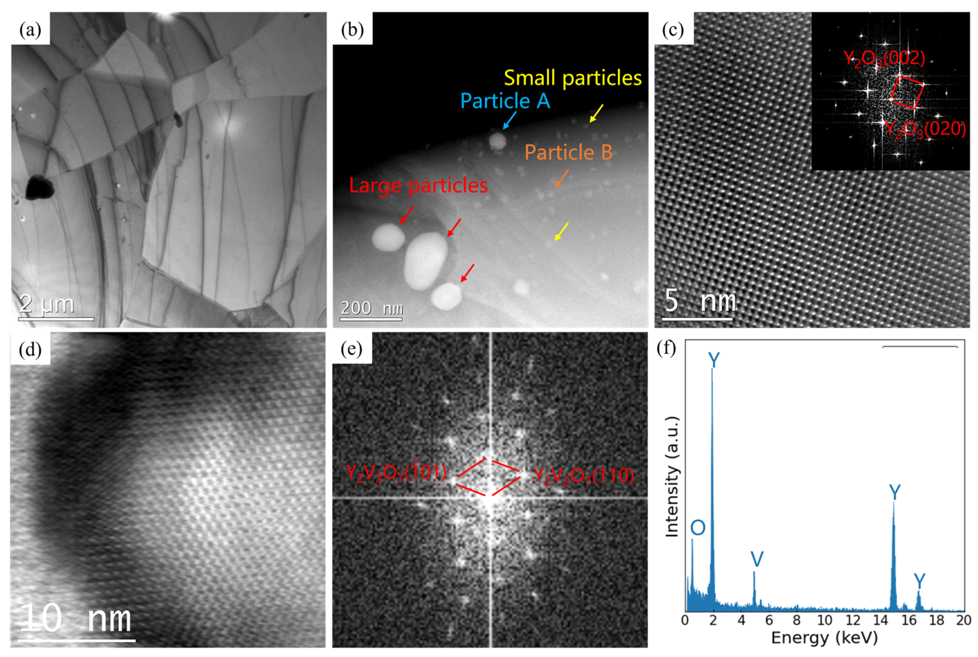
3.1. Microstructure Analysis
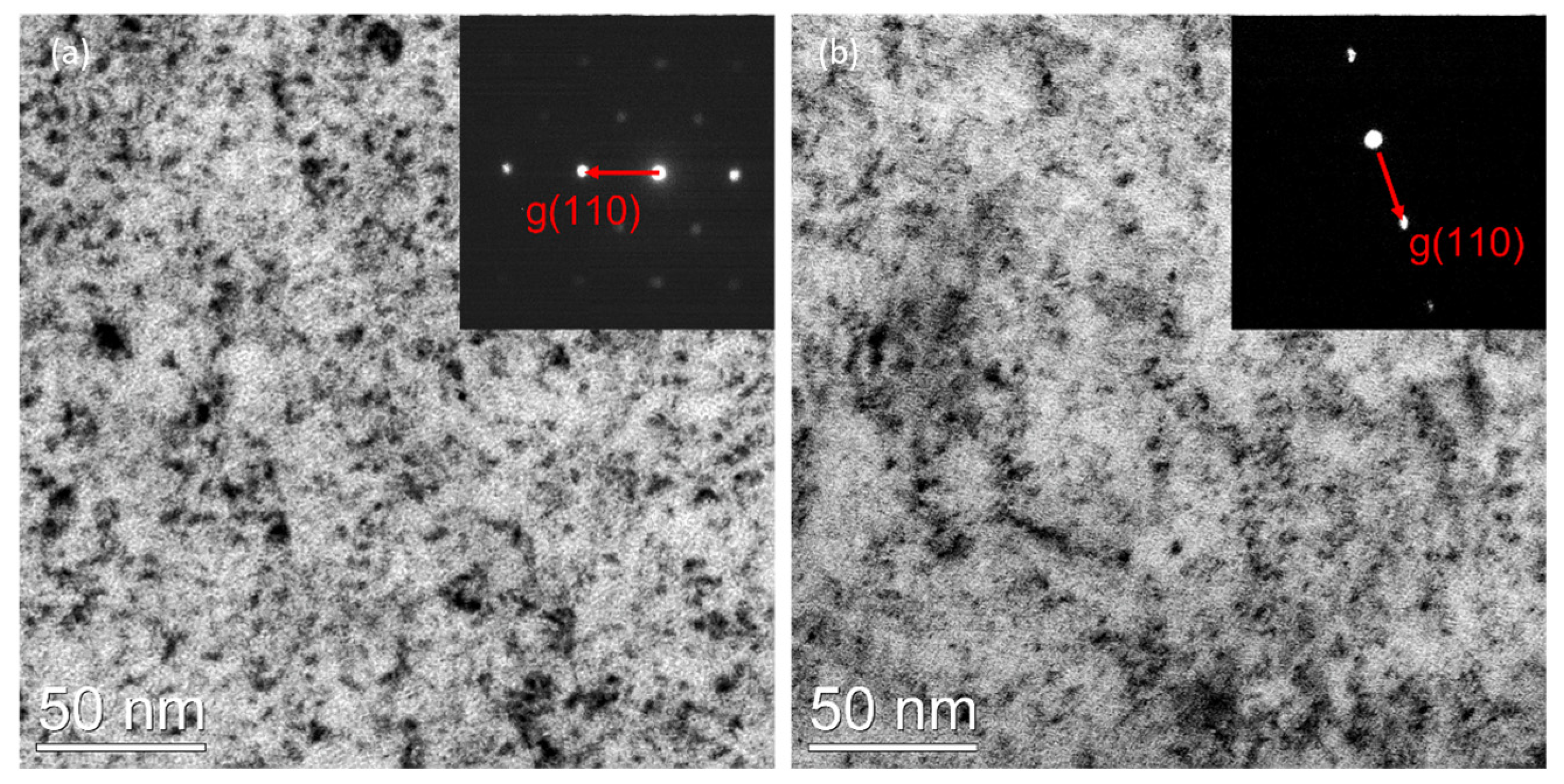
3.2. Radiation-Induced Dislocation Loop
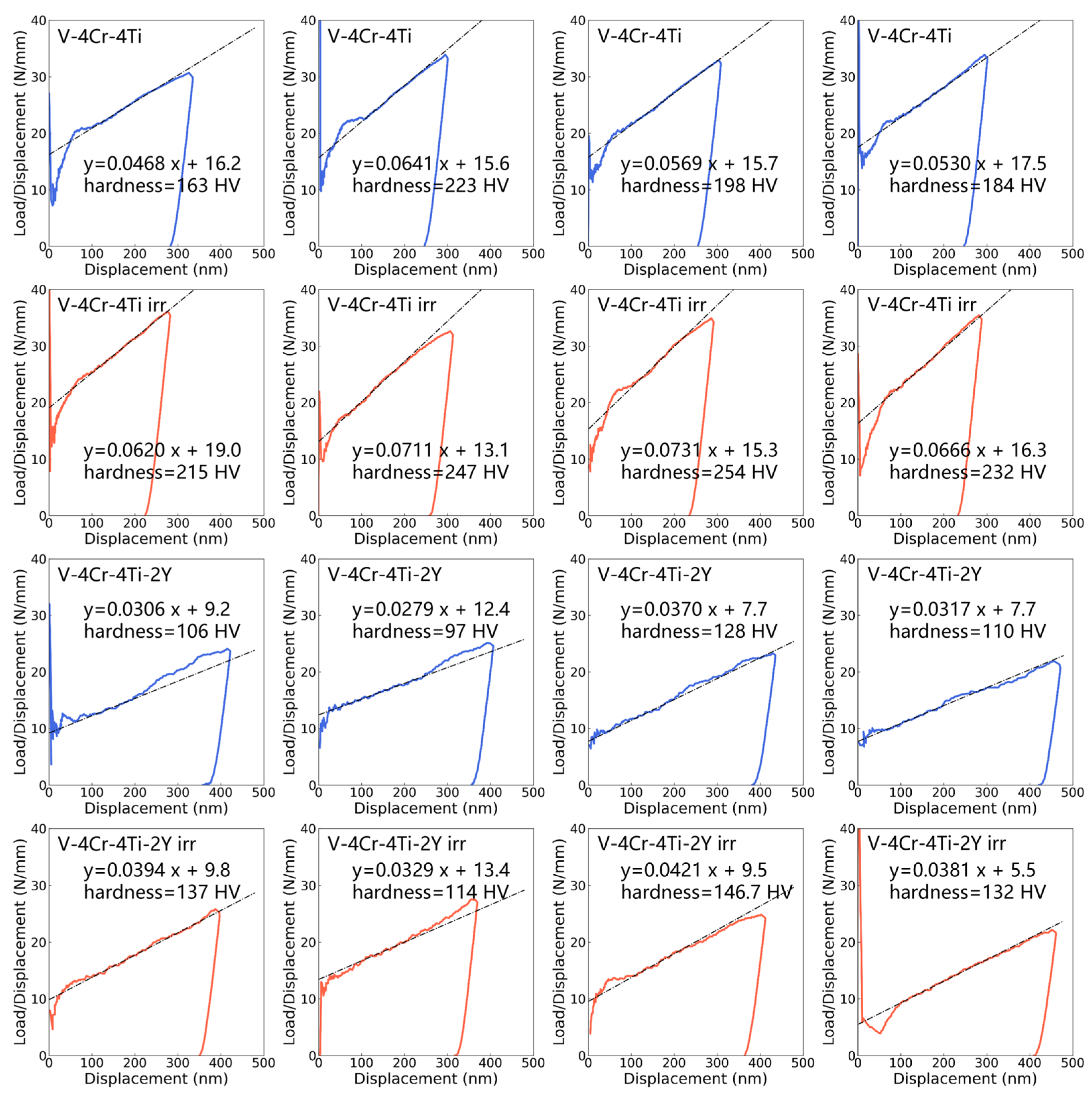
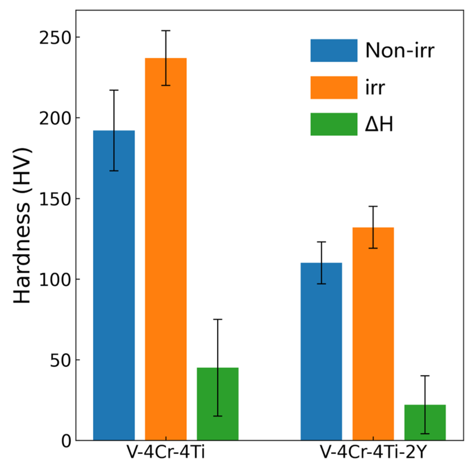
3.3. Radiation Hardening
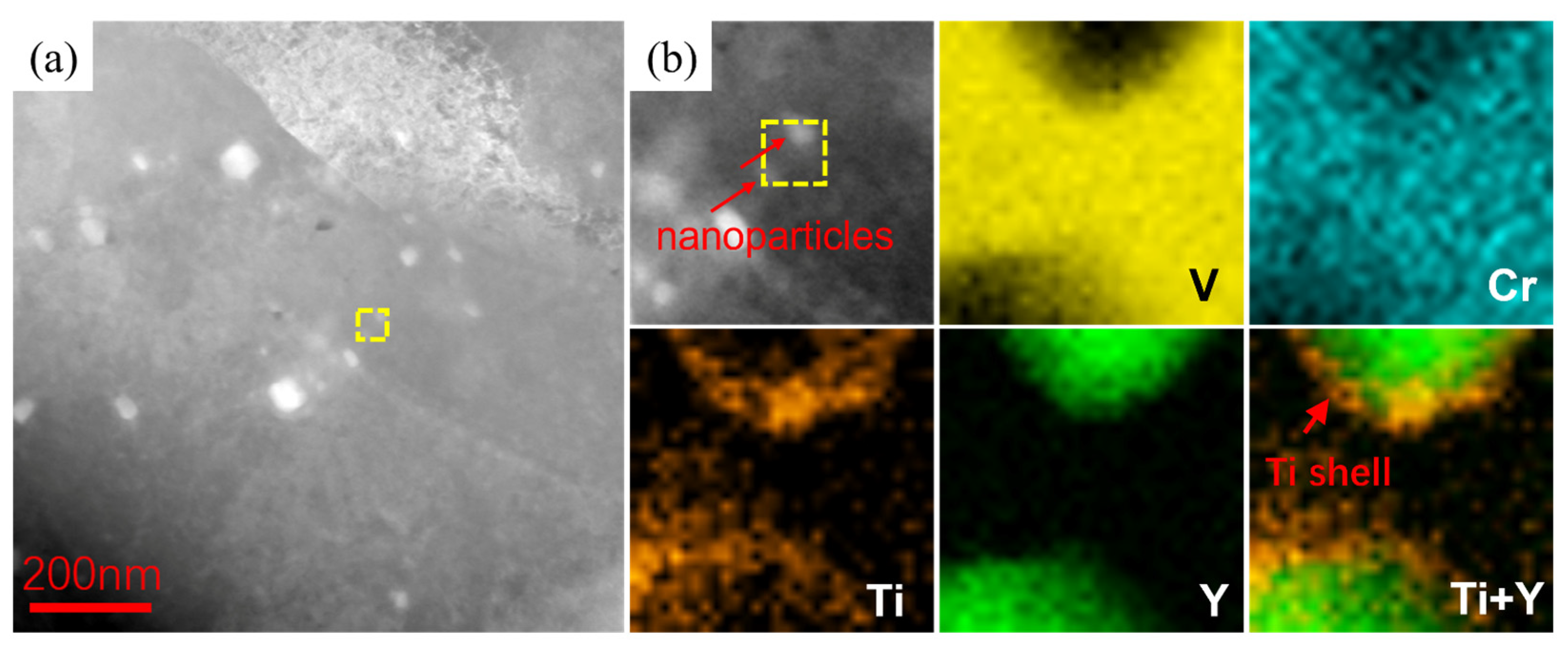
3.4. Ti-Rich Segregation
4. Conclusions
- The formation of large Y2O3 and small Y2V2O7 nanoparticles was confirmed, indicating that the addition of Y reduces the amount of dissolved oxygen, resulting in the formation of Y-rich oxide nanoparticles.
- The addition of Y reduces the size of radiation-induced dislocation loops and slightly reduces radiation hardening after room temperature irradiation. Possible causes for this include the strong sink strength of the nanoparticle/matrix interface, interactions between Y atoms and SIA clusters, and the strong binding energy of vacancy–oxygen pairs.
- Ti-rich shells coated with Y-rich particles were observed in the sublayer near the surface of the Y-doped V-4Cr-4Ti alloy after irradiation at room temperature, proving that the addition of Y in the V-4Cr-4Ti alloy affects Ti segregation. Possible causes for this include the lower interface energy at the particle/matrix interface and the interaction between oxygen and solute atoms.
Author Contributions
Funding
Data Availability Statement
Acknowledgments
Conflicts of Interest
References
- Muroga, T.; Chen, J.M.; Chernov, V.M.; Kurtz, R.J.; Le, F.M. Present status of vanadium alloys for fusion applications. J. Nucl. Mater. 2014, 455, 263–268. [Google Scholar] [CrossRef]
- Li, Z.D.; Li, Q.; Li, Y.; Ma, T.D. Microstructure and properties of V–5Cr–5Ti alloy after hot forging. Fusion Eng. Des. 2018, 127, 83–90. [Google Scholar] [CrossRef]
- Pint, B.A.; Pawel, S.J.; Howell, M.; Moser, J.L.; Garner, G.W.; Santella, M.L.; Tortorelli, P.F.; Wiffen, F.W.; DiStefano, J.R. Initial characterization of V–4Cr–4Ti and MHD coatings exposed to flowing Li. J. Nucl. Mater. 2009, 386, 712–715. [Google Scholar] [CrossRef]
- Chen, J.M.; Chernov, V.M.; Kurtz, R.J. Overview of the vanadium alloy researches for fusion reactors. J. Nucl. Mater. 2011, 417, 289–294. [Google Scholar] [CrossRef]
- Muroga, T. Vanadium for Nuclear Systems. Compr. Nucl. Mater. 2012, 4, 391–406. [Google Scholar]
- Duquesnes, V.; Guilbert, T.; Flem, M.L. French investigation of a new V–4Cr–4Ti grade: CEA-J57–Fabrication and microstructure. J. Nucl. Mater. 2012, 426, 96–101. [Google Scholar] [CrossRef]
- Zhu, B.; Yang, S.; Ding, J.; Zhang, W.; Long, Y.; Wan, F. Abnormal hardening effect induced by the lath-like precipitates in the V-4Cr-4Ti alloy. Mater. Lett. 2015, 161, 609–612. [Google Scholar] [CrossRef]
- Jiang, S.N.; Xu, L.Q.; Wan, F.R. Effect of precipitates on high-temperature strength and irradiation behavior of vanadium-based alloys. J. Iron Steel Res. Int. 2018, 25, 1270–1277. [Google Scholar] [CrossRef]
- Muroga, T.; Nagasaka, T.; Watanabe, H.; Yamazaki, M. The effect of final heat treatment temperature on radiation response of V-4Cr-4Ti. J. Nucl. Mater. 2011, 417, 310–313. [Google Scholar] [CrossRef] [Green Version]
- Zhang, X.M.; Li, Y.F.; Tang, J.F.; Deng, L.; Li, W.; Wang, L.; Deng, H.Q.; Hu, W.Y. Precipitate/vanadium interface and its strengthening on the vanadium alloys: A first-principles study. J. Nucl. Mater. 2019, 527, 151821. [Google Scholar] [CrossRef]
- Zhang, X.; Tang, J.; Deng, L.; Zhong, G.; Liu, X.; Li, Y.; Deng, H.; Hu, W. The effects of interstitial impurities on the mechanical properties of vanadium alloys: A first-principles study. J. Alloys Compd. 2017, 701, 975–980. [Google Scholar] [CrossRef]
- Luo, H.T.; Luo, F.F.; Chen, Y.H.; Wang, J.W.; Liu, Q.X.; Li, F.; Xie, Z.Y.; Lin, W.B.; Guo, L.P. Effect of yttrium content on microstructure and irradiation behavior of V-4Cr-4Ti-xY alloys. J. Nucl. Mater. 2022, 559, 153480. [Google Scholar] [CrossRef]
- Zhang, Y.F.; Li, R.R.; Diao, S.Z.; Wan, F.R.; Zhan, Q. Plasticity Improvement and Radiation Hardening Reduction of Y Doped V-4Cr-4Ti Alloy. J. Nucl. Mater. 2022, 560, 153508. [Google Scholar] [CrossRef]
- Watanabe, H.; Muroga, T.; Nagasak, T. Effects of Irradiation Environment on V–4Cr–4Ti Alloys. Plasma Fusion Res. 2017, 12, 2405011. [Google Scholar] [CrossRef] [Green Version]
- Watanabe, H.; Higashijima, A.; Yoshida, N.; Nagasaka, T.; Muroga, T. The microstructure of laser welded Y doped V-4Cr-4Ti alloys after ion irradiation. J. Nucl. Mater. 2009, 386, 598–601. [Google Scholar] [CrossRef] [Green Version]
- Watanabe, H.; Yamasaki, K.; Higashijima, A.; Taguma, H.; Nagasaka, T.; Muroga, T. Microstructural changes of Y-doped V-4Cr-4Ti alloys after ion and neutron irradiation. Nucl. Mater. Energy 2016, 9, 447–450. [Google Scholar] [CrossRef] [Green Version]
- Zheng, P.F.; Chen, J.M.; Nagasaka, T.; Muroga, T.; Zhao, J.J.; Xu, Z.Y.; Li, C.H.; Fu, H.Y.; Chen, H.; Duan, X.R. Effects of dispersion particle agents on the hardening of V–4Cr–4Ti alloys. J. Nucl. Mater. 2014, 455, 669–675. [Google Scholar] [CrossRef]
- Duan, X.R.; Chen, J.M.; Feng, K.M.; Liu, X.; Li, B.; Wu, J.H.; Wang, X.Y.; Zheng, P.F.; Wang, Y.Q.; Wang, P.H.; et al. Progress in fusion technology at SWIP. Fusion Eng. Des. 2016, 109, 1022–1027. [Google Scholar] [CrossRef]
- Zhang, Y.F.; Du, J.K.; Liu, P.P.; Zheng, P.F.; Yang, S.W.; Wan, F.R.; Zhan, Q. Response of microstructure and hardening to deuterium ion irradiation inV-4Cr-4Ti-1.8Y-0.4Ti3SiC2 and V-4Cr-4Ti alloy. Fusion Eng. Des. 2020, 159, 111789. [Google Scholar] [CrossRef]
- Krishnan, V.K.; Sinnaeruvadi, K.; Verma, S.K.; Dash, B.; Agrawal, P.; Subramanian, K. Yttria catalyzed microstructural modifications in oxide dispersion strengthened V–4Cr–4Ti alloys synthesized by field assisted sintering technique. Philos. Mag. 2017, 97, 1847–1865. [Google Scholar] [CrossRef]
- Stoller, R.E.; Toloczko, M.B.; Was, G.S.; Certain, A.G.; Dwaraknath, S.; Garner, F.A. On the use of SRIM for computing radiation damage exposure. Nucl. Instrum. Methods Phys. Res. Sect. B Beam Interact. Mater. At. 2013, 310, 75–80. [Google Scholar] [CrossRef]
- NRT ASTM E521; Standard Practice for Neutron Radiation Damage Simulation by Charged-Particle Irradiation. ASTM International, Annual Book of ASTM Standards; ASTM: Philadelphia, PA, USA, 1996.
- Stringer, J. The vanadium-oxygen system—A review. J. Less Common Met. 1965, 8, 1–14. [Google Scholar] [CrossRef]
- Zhang, L.; Du, Y.F.; Han, W.T.; Liu, P.P.; Yi, X.O.; Yabuuchi, K.; Ohnuki, S.; Wan, F.R. An approximate in-situ method for investigating irradiation damage of grain boundary. Nucl. Mater. Energy 2021, 29, 101056. [Google Scholar] [CrossRef]
- Diao, S.Z.; Zhao, Q.; Wang, S.L.; Han, W.T.; Wang, Z.Q.; Liu, P.P.; Chen, Y.H.; Wan, F.R.; Zhan, Q. The microstructure evolution and irradiation hardening in 15Cr-ODS steel irradiated by helium ions. Mater. Charact. 2022, 184, 111699. [Google Scholar] [CrossRef]
- Zhang, Y.F.; Zhan, Q.; Ohnuki, S.; Kimura, A.; Wan, F.R.; Yoshida, K.; Nagai, Y. Radiation-hardening and nano-cluster formation in neutron-irradiated 9Cr2W low activation steels with different Si contents. J. Nucl. Mater. 2019, 517, 1–8. [Google Scholar] [CrossRef]
- Was, G.S. Fundamentals of Radiation Materials Science: Metals and Alloys; Springer: Berlin/Heidelberg, Germany, 2016. [Google Scholar]
- Yu, H.Q.; Wang, S.L.; Zhang, Y.F.; Liu, Q.; Diao, S.Z.; Liu, P.P.; Oono, N.H.; Ukai, S.; Wan, F.R.; Ohnuki, S.; et al. Response of nanoclusters to heavy-ion irradiation in an Fe-12Cr ODS steel. Fusion Eng. Des. 2021, 172, 112759. [Google Scholar] [CrossRef]
- Deng, L.; Tang, L.Z.; Zhang, X.M.; Tang, J.F.; Li, R.L.; Deng, H.Q. Ab initio solute–interstitial impurity interactions in vanadium alloys: The roles of vacancy. RSC Adv. 2016, 6, 78621–78628. [Google Scholar] [CrossRef]
- Candra, L.; Fukumoto, K.; Kimura, A.; Matsui, H. Microstructural evolution and hardening of neutron irradiated vanadium alloys at low temperatures in Japan Material Testing Reactor. J. Nucl. Mater. 1999, 271, 301–305. [Google Scholar] [CrossRef]
- Zhang, P.B.; Wei, M.L.; Li, Y.G.; Zhao, J.J.; Zheng, P.F.; Chen, J.M. Interactions of solute atoms with self-interstitial atoms/clusters in vanadium: A first-principles study. J. Nucl. Mater. 2021, 553, 153055. [Google Scholar] [CrossRef]
- Iwakiri, H.; Wakimoto, H.; Watanabe, H.; Yoshida, N. Hardening behavior of molybdenum by low energy He and D ion irradiation. J. Nucl. Mater. 1998, 258–263, 873–878. [Google Scholar] [CrossRef]
- Jiang, S.N.; Xu, L.Q.; Zheng, P.F. Evaluation of hardening behavior under synergistic interaction of He and subsequent H ions irradiation in vanadium alloys. Nucl. Mater. Energy 2018, 16, 19–23. [Google Scholar] [CrossRef]
- Meyers, M.A. Mechanical Behavior of Materials; Cambridge University Press: Cambridge, UK, 2009; Chapter 4: Imperfections: Point and Line Defects. [Google Scholar]
- Busby, J.T.; Hash, M.C.; Was, G.S. The relationship between hardness and yield stress in irradiated austenitic and ferritic steels. J. Nucl. Mater. 2005, 336, 267–278. [Google Scholar] [CrossRef]
- Ribis, J.; Bordas, E.; Trocellier, P.; Serruys, Y.; Carlan, Y.; Legris, A. Radiation-sustained nanocluster metastability in oxide dispersion strengthened materials. Nucl. Instrum. Methods Phys. Res. Sect. B Beam Interact. Mater. At. 2015, 365, 22–25. [Google Scholar] [CrossRef]
- Jung, H.J.; Edwards, D.J.; Kurtz, R.J.; Yamamoto, T.; Wu, Y.; Odette, G.R. Structural and chemical evolution in neutron irradiated and helium-injected ferritic ODS PM2000 alloy. J. Nucl. Mater. 2017, 484, 68–80. [Google Scholar] [CrossRef] [Green Version]
- Sakasegawa, H.; Chaffron, L.; Legendre, F.; Boulanger, L.; Cozzika, T.; Brocq, M.; Carlan, Y. de Correlation between chemical composition and size of very small oxide particles in the MA957 ODS ferritic alloy. J. Nucl. Mater. 2009, 384, 115–118. [Google Scholar] [CrossRef]
- Sakasegawa, H.; Legendre, L.; Boulanger, L.; Brocq, M.; Chaffron, L.; Cozzika, T.; Malaplate, J.; Henry, J.; Carlan, Y. de Stability of non-stoichiometric clusters in the MA957 ODS ferrtic alloy. J. Nucl. Mater. 2011, 417, 229–232. [Google Scholar] [CrossRef]
- Swenson, M.J.; Wharry, J.P. The comparison of microstructure and nanocluster evolution in proton and neutron irradiated Fe-9% Cr ODS steel to 3 dpa at 500 C. J. Nucl. Mater. 2015, 467, 97–112. [Google Scholar] [CrossRef] [Green Version]
- Slater, J.C. Atomic radii in crystals. J. Chem. Phys. 1964, 41, 3199–3204. [Google Scholar] [CrossRef]


| Materials | Cr | Ti | Zr | C | N | O | Y | V |
|---|---|---|---|---|---|---|---|---|
| V-4Cr-4Ti | 4.62 | 4.22 | 0.08 | 0.02 | 0.04 | 0.21 | - | Bal. |
| V-4Cr-4Ti-2Y | 4.38 | 4.06 | 0.03 | 0.02 | 0.04 | 0.24 | 1.86 | Bal. |
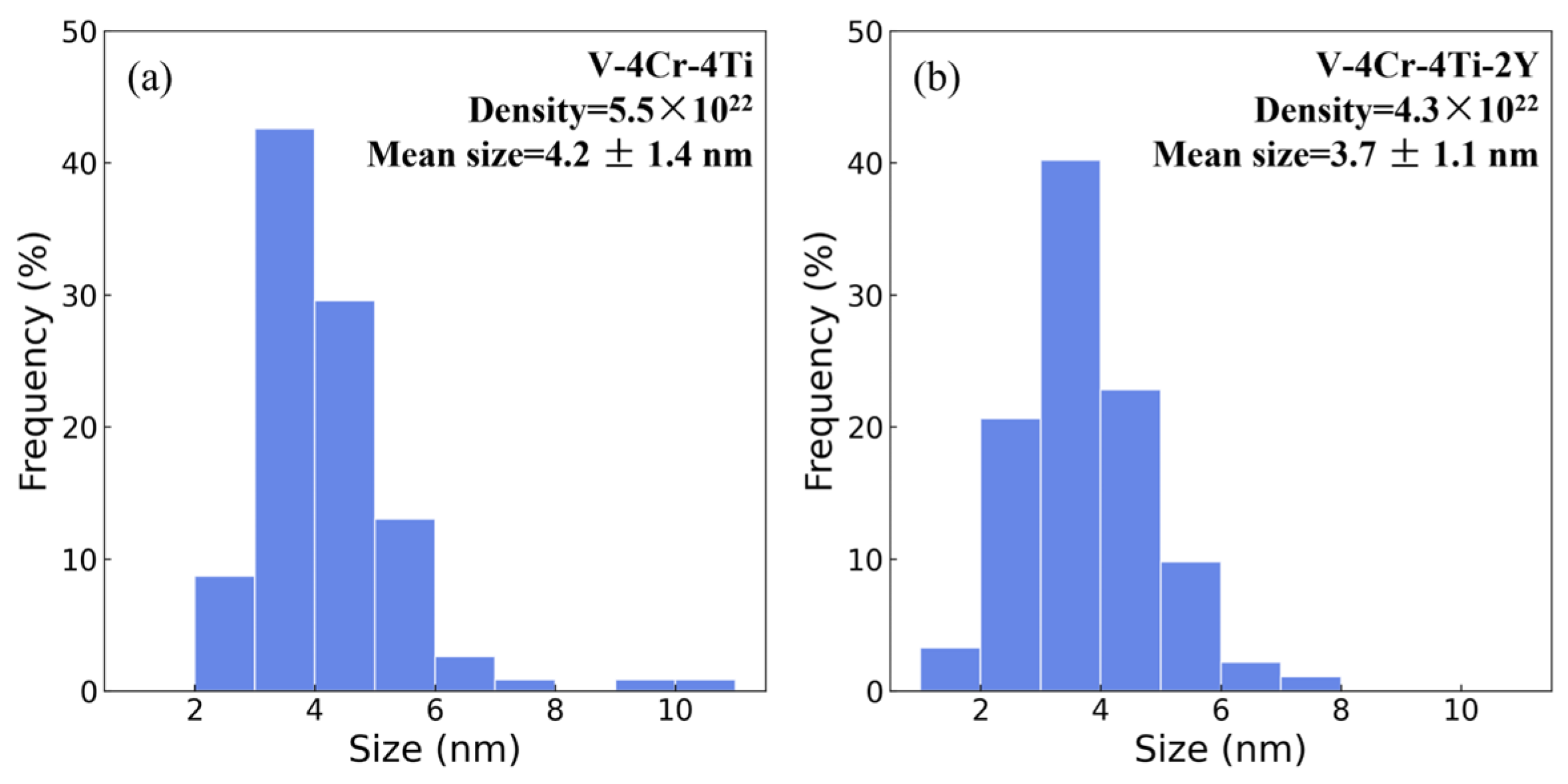
| Materials | Population | Number Density ρ (m−3) | Mean Size D (nm) |
|---|---|---|---|
| V-4Cr-4Ti | 115 | 5.5 × 10²² | 4.2 ± 1.4 |
| V-4Cr-4Ti-2Y | 92 | 4.3 × 10²² | 3.7 ± 1.1 |
| t Statistic | DF | Prob > |t| | |
|---|---|---|---|
| Equal Variance Assumed | −3.11 | 205 | 0.0022 |
| Equal Variance NOT Assumed (Welch Correction) | −3.18 | 204.99 | 0.0017 |
| t Statistic | DF | Prob > |t| | |
|---|---|---|---|
| Equal Variance Assumed | 2.84 | 203 | 0.0050 |
| Equal Variance NOT Assumed (Welch Correction) | 2.93 | 202.96 | 0.0038 |
Disclaimer/Publisher’s Note: The statements, opinions and data contained in all publications are solely those of the individual author(s) and contributor(s) and not of MDPI and/or the editor(s). MDPI and/or the editor(s) disclaim responsibility for any injury to people or property resulting from any ideas, methods, instructions or products referred to in the content. |
© 2023 by the authors. Licensee MDPI, Basel, Switzerland. This article is an open access article distributed under the terms and conditions of the Creative Commons Attribution (CC BY) license (https://creativecommons.org/licenses/by/4.0/).
Share and Cite
Zhang, Y.; Sun, X.; Ma, B.; Wang, J.; Luo, L.; Wu, Y. Investigation of the Y Effect on the Microstructure Response and Radiation Hardening of PM V-4Cr-4Ti Alloys after Irradiation with D Ions. Metals 2023, 13, 541. https://doi.org/10.3390/met13030541
Zhang Y, Sun X, Ma B, Wang J, Luo L, Wu Y. Investigation of the Y Effect on the Microstructure Response and Radiation Hardening of PM V-4Cr-4Ti Alloys after Irradiation with D Ions. Metals. 2023; 13(3):541. https://doi.org/10.3390/met13030541
Chicago/Turabian StyleZhang, Yifan, Xiaoyuan Sun, Bing Ma, Jing Wang, Laima Luo, and Yucheng Wu. 2023. "Investigation of the Y Effect on the Microstructure Response and Radiation Hardening of PM V-4Cr-4Ti Alloys after Irradiation with D Ions" Metals 13, no. 3: 541. https://doi.org/10.3390/met13030541
APA StyleZhang, Y., Sun, X., Ma, B., Wang, J., Luo, L., & Wu, Y. (2023). Investigation of the Y Effect on the Microstructure Response and Radiation Hardening of PM V-4Cr-4Ti Alloys after Irradiation with D Ions. Metals, 13(3), 541. https://doi.org/10.3390/met13030541