Article

Microstructure Evolution and Effect on Deuterium Retention in TiC- and ZrC-Doped Tungsten under He+ Ion Irradiation

1
Institute of Laser Advanced Manufacturing, Zhejiang University of Technology, Hangzhou 310014, China
2
College of Mechanical Engineering, Zhejiang University of Technology, Hangzhou 310014, China
3
Collaborative Innovation Center of High-End Laser Manufacturing Equipment (National “2011 Plan”), Zhejiang University of Technology, Hangzhou 310014, China
4
Institute for Integrated Radiation and Nuclear Science, Kyoto University, Osaka 590-0494, Japan
5
School of Materials Science and Engineering, Hefei University of Technology, Hefei 230009, China
*
Author to whom correspondence should be addressed.
Metals 2023, 13(4), 783; https://doi.org/10.3390/met13040783
Submission received: 10 February 2023 / Revised: 13 March 2023 / Accepted: 6 April 2023 / Published: 17 April 2023

Abstract

:
Combining the advantages of a wet chemical method and spark plasma sintering, carbide-doped materials W-1wt%TiC and W-1wt%ZrC were prepared. Microstructural evolution in W-1wt%TiC and W-1wt%ZrC under irradiation of 5 keV He+ at 600 °C to fluences up to 5.0 × 10²¹ ions/m2 with ion flux of about 8.8 × 10¹⁷ ions/m2s was investigated by transmission electron microscopy (TEM). The dislocation loop number density of W-1wt%TiC was higher than that of W-1wt%ZrC, but the average loop size of the W-1wt%TiC was in average smaller. There were no observable helium bubbles in W-1wt%TiC and W-1wt%ZrC, exhibiting higher radiation resistance to He+ compared to pure W. He+ pre-damaged and undamaged W-1wt%TiC and W-1wt%ZrC samples were irradiated by 5 keV D2+ to estimate the D retention in doped W materials. The irradiation damage impact of He+ on deuterium retention was examined by a method of thermal desorption spectroscopy (TDS). Compared with the undamaged samples, it was illustrated that D2 retention of W-1wt%TiC and W-1wt%ZrC increased after He+ pre-irradiation.

1. Introduction

Material issues have long been, and still are, a major barrier to fusion reactor. Plasma-facing (first wall, divertor) materials (PFMs), used as armor of underlying materials, have to withstand high thermal load as well as radiation fields, due to plasma–material interaction. The principle of choosing PFMs depends on their ability to absorb heat and reduce plasma contamination. W has been recognized as the most promising PFM candidate for nuclear fusion reactors because of unique properties [1,2], such as extremely high melting point, excellent thermal conductivity, high sputtering resistance, and low tritium retention rate, etc. [3,4]. However, interaction of various energetic particles such as hydrogen isotopes, helium, and neutrons with the W lattice will result in the formation of defects including interstitial dislocations loops, vacancy clusters, He bubbles, and cavities. The defects will further lead to material embrittlement and hardening as well as failure in service. He and/or gaseous H2 atoms produced by nuclear transmutation reactions can result in macroscopic swelling of W, causing the loss of dimensional stability. According to current understanding, morphological changes (bubbles, nanostructure, fuzz, pores, and blister formation) emerge from helium bubble formation near the projected damage region. A lot of recent studies have focused on development of advanced W-based materials that may bring better radiation resistance [5], for the sake of eliminating irradiation damage in W under high-heat and high-flux plasma service conditions for fusion power reactors (ITER, DEMO, and beyond).
Among the possible improvements, dispersed second-phase particles (rare-earth oxides and transition metal carbides) can serve as points of annihilation for irradiation-induced defects, consequently enhancing the radiation resistance of W. Fine ceramic particles such as La2O3, Y2O3, ZrC, TaC, TiC, and HfC have been introduced into the W matrix to improve high-temperature strength through hindering grain growth and limiting dislocation movement [6,7,8,9,10]. Among ceramics, TiC and ZrC are intriguing on account of their high melting point and low vapor pressure compared with La2O3 and Y2O3, and the similarity of their thermal and mechanical properties to pure W.
Owing to the importance of W for fusion reactors, the hydrogen isotope retention properties in W originating from loading or injection of energetic H (molecules, ions, neutrals, plasmas) cause extensive concern. Consequently, it seems necessary to assess the hydrogen isotope retention behavior of doped W materials regarding their potential applications in fusion devices. Unlike interaction of hydrogen gas with W, energetic ion implantation is often accompanied by the formation of various defects which attract or trap H, making the behavior of H impinged in W pretty complex [11]. It is commonly admitted that H can be generally trapped by radiation-induced defects, and He may produce defects and be trapped by defects [12]. Moreover, He will be trapped strongly by themselves in W even in the absence of lattice defects because the binding energies of He with He atoms at interstitial sites are well above thermal energies [13]. Accordingly, He ion irradiation of W would lead to more serious damage than that of H [14].
In the present work, fine-grained carbide TiC (ZrC)-doped W materials were prepared via a wet chemical method, and then sintered by the spark plasma sintering (SPS) technique. The microstructure evolution of W-TiC and W-ZrC under 5 keV He+ irradiation at 600 °C was systematically analyzed by varying ion influence, expecting to elucidate the underlying mechanisms controlling irradiation damage evolution. The deuterium retention in He+ pre-damaged samples was explored by a method of thermal desorption spectroscopy (TDS) to investigate the influence of He+ irradiation on deuterium retention in carbide-doped W materials.

2. Experimental Procedure

2.1. Samples

W doped with 1wt%TiC (ZrC) was fabricated by mixing (NH4)6H2W12O40·xH2O (AMT), nano-sized TiC (ZrC) powders, and oxalic acid (C2H2O4·2H2O) in an aqueous solution. TiC (ZrC) powders dispersed by ultrasonic were added into AMT solution with continuous stirring, and then oxalic acid was added to facilitate precipitation of the precursor. The precursor powder was precipitated from the solution because of solution evaporation at 180 °C, when enhanced oxalic acid concentration accelerated the coating of TiC (ZrC) particles by AMT. After washing, filtering, and drying, the precursor powders were reduced in the single-tube electrically heated furnace with high-purity hydrogen. The as-synthesized powders were heated to 800 °C at a heating rate of 5 °C/min and kept for 6 h. The surface morphology of the reduced doped powders was characterized through field emission scanning electron microscope (SEM).
The reduced powders were sintered at 1700 °C under vacuum by SPS (LABOX-350). The as-sintered samples were 20 mm in diameter and 2.0–3.0 mm in thickness. The crystallographic features of the prepared materials were examined using X-Ray diffraction (D/MAX 2500V) with Cu source and λ = 1.54 Å, in the range of 10–90° and with a scanning rate of 8°/min. The density of the samples was measured with the drainage method. Hardness of sintered samples was determined by Vickers microhardness testing using MH-3L under a 200 g load applied for 20 s in every similar area. The thermal conductivities of the samples were obtained by a laserflash thermal analyzer (LFA 457). Sample surfaces for observation were polished and then etched by the etchant of boiling hydrogen peroxide (60% concentration): ammonia aqueous solution. The surface morphology and fracture features of the as-sintered W-1wt%TiC and W-1wt%ZrC were observed by SEM.

2.2. He+ Irradiation at 600 °C

For observing microstructure evolution of carbide-doped W irradiated by 5 keV He+ ions, TEM samples were fabricated by 15 V twin-jet electropolishing using 2% NaOH aqueous solution. Irradiation of W-1wt%TiC and W-1wt%ZrC with He+ ions to fluences up to 5 × 10²¹ ions/m2 with a flux of 8.8 × 10¹⁷ ions/m2s at a sample temperature of 600 °C was performed at the low-energy ion irradiation system at the Institute for Integrated Radiation and Nuclear Science in Kyoto University. The radiation damage of W and doped W was compared comprehensively through post-irradiation analysis. To perform dislocation loop density and size analysis, dislocations were counted and measured on TEM micrographs in different areas of both samples to determine quantitative information of damage [2,15].

2.3. Deuterium Retention Analysis by TDS

Prior to implantation by keV He+ at the fluence of 1.0 × 10²¹ ions/m2 using an Omegatron gun at room temperature (RT), each sample was cut by electric discharge machining to a size of Φ5 mm, and then polished to a mirror finish, and finally cleaned by ultrasonic in the acetone ultrasonic bath. Subsequently, He+ pre-damaged and undamaged W-1wt%TiC and W-1wt%ZrC were implanted by 5 keV D2+ at doses of 1.0 × 10²⁰ D2+/m2, 1.0 × 10²¹ D2+/m2, and 1.0 × 10²² D2+/m2 with a flux of 2.2 × 10¹⁷ ions/m2s at RT. The background pressure in the chamber was better than 10−4 Pa. The D2+ was collimated and mass analyzed, and beam flux was monitored via a Faraday cup. The He molecule was excluded, because it is hard to find the desorption peaks of He trapped by these defects even at 1500 K in W, owing to the high binding energy of He and defects. Then, the samples were transferred to the TDS facility, where the behavior of deuterium release from the carbide-doped samples was examined with a maximum temperature of 1173 K in a vacuum (<10−6 Pa) at a line heating rate of 1 K/s through an infrared heater. Calibration of the high-resolution quadrupole mass spectrometer was carried out by a standard deuterium leak bottle before TDS measurements so that the calibrated release rate during TDS could reliably be determined. The mass three signal was ignored, because the HD flux contributed little to the total D flux. The total amount of retained D in doped W materials was obtained from TDS curves by integrating the desorption rate over the time. According to calculations using SRIM code with the quick Kinchin–Pease option, the implanted He and D2 ions lay approximately 0–80 nm and 0–60 nm from the incident surface, respectively [16]. An average displacement damage threshold of 90 eV for the W lattice was used.

3. Results

3.1. Synthesized Doped W Powders and SPS Sintered Samples

The surface morphology of reduced powders after reducing by hydrogen visible by SEM is shown in Figure 1a,b. There are no obvious second-phase particles discovered on the W surface, demonstrating that insoluble TiC and ZrC carbides acted as a heterogeneous nucleation site, facilitating them to be well-coated by W. The reduced powders of W-1wt%TiC and W-1wt%ZrC consist of two different kinds of morphologies, i.e., larger particles of polygonal and smaller particles of quasi-sphere shape.
The etched surface micrographs of the W-1wt%TiC and W-1wt%ZrC consolidated by SPS are presented in Figure 2. As shown in Figure 2a,b, whiter grains were W grains, and the black grains were carbide particles. TiC and ZrC particles displayed good dispersibility into the W matrix, which was evidence of the uniform mixing of AMT and insoluble TiC and ZrC particles during the wet chemical process. As illustrated in Figure 2, W-1wt%TiC and W-1wt%ZrC displayed nearly fully dense surface, in accordance with their high relative density. The relative density of W-1wt%TiC was 98.6%, higher than W-1wt%ZrC with 97.2%. It was verified that W-1wt%TiC had a better sinterability than that of W-1wt%ZrC. The resulting XRD pattern (see Figure 3) indicated that no new phases formed during SPS consolidation. There were no TiC and ZrC peaks detected on XRD, implying the low doping content of second-phase particles.
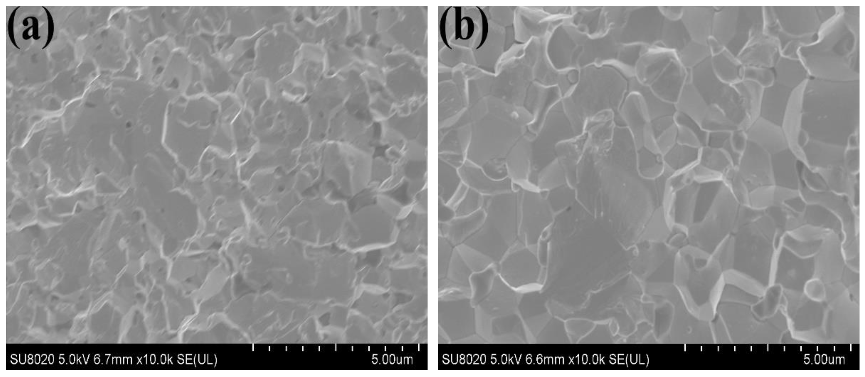
The fracture surface morphology of the W-1wt%TiC and W-1wt%ZrC are presented in Figure 4a,b, respectively. As shown in the figures, fracture appearances of both samples were brittle at RT, displaying typical intergranular failure. The average grain size of sintered W-1wt%TiC and W-1wt%ZrC samples was about 3 μm, as listed in Table 1. The Vickers hardness value of W-1wt%TiC was higher than W-1wt%ZrC due to its higher relative density. The thermal conductivities of the W-1wt%TiC and W-1wt%ZrC at RT were also shown in Table 1. The value of W-1wt%ZrC was slightly lower than W-1wt%TiC, but the thermal conductivity of both doped W materials was above 110 W/m·K at RT.

3.2. Microstructural Evolution under 5 keV He+ Irradiation

The samples were characterized through TEM before and after irradiation by He+ bombardment. The unirradiated carbide-doped W samples contained an almost-negligible number of pre-existing dislocations. As shown in Figure 5, carbide particles were dispersed in the W matrix, and the average grain size of second particles was about 50–100 nm (marked by arrows).
The key point to understand the evolution of damage microstructures is observation of the dynamical behavior of loops [15]. Observed irradiation defects included dislocation loops, networks, and He bubbles, depending on the irradiation condition. To elaborate the He+ ion irradiation dose dependence of defect microstructures in W-1wt%TiC and W-1wt%ZrC at 600 °C, the TEM specimens irradiated with 5 keV He+ at the fluence of 1.0 × 10²⁰ He+/m2, 1.0 × 10²¹ He+/m2, and 5.0 × 10²¹ He+/m2.The defect microstructure of 5 keV He+-irradiated pure W specimens at RT was investigated as a reference for comparison. Commercial pure W samples (polycrystalline W, 99.95%) used in the present study were obtained from Allied Material Corporation.
The TEM Images of the pure W exposed to the fluence of 1.0 × 10²⁰ He+/m2, 1.0 × 10²¹ He+/m2, and 5.0 × 10²¹ He+/m2 at RT are shown in Figure 6a–c, respectively. At the initial stage of He+ irradiation, small dislocation loops were formed with a loop number volume density approximately of 3.8 × 10²²/m3, and the mean dislocation loop diameter was about 6.4 nm. The dislocation loops were mainly of interstitial type, and were easily identifiable under this as-irradiated condition. It is believed that the migration of vacancies and the vacancy–helium complexes from strong interaction of vacancies and helium do not occur at RT (vacancy migration energy in W is about 1.7 eV) [2], while the interstitials (interstitial migration energy of W is about 0.08 eV) could move freely even at RT, and then form dislocation loops of interstitial type. With the increase in irradiation dose, the movement of individual loops and interaction with close neighbors became dominant in the damage microstructure. Up to the end fluence of 5.0 × 10²¹ He+/m2, He bubbles around 1 nm in size were observed, appearing as bright spots in the TEM micrographs. These He bubbles were evenly distributed in the matrix without obvious orientation.
Defect formation and evolution were also observed in doped W under He+ ion irradiation, shown in Figure 7 and Figure 8, respectively. At a low dose of 1.0 × 10²⁰ He+/m2, the microstructure was characteristic of small dislocation loops, which were randomly distributed inside both W-1wt%TiC and W-1wt%ZrC samples. The size of dislocation loop in different irradiated samples was completely different. The number densities of W-1wt%TiC were on the order of 1.0 × 10²³, higher than that of W-1wt%ZrC with 1.0 × 10²². The dislocation loops in W-1wt%TiC samples showed a fine dispersion distribution, and the average dislocation loop size was 2.1 nm, which was much smaller than W-1wt%ZrC of 12.8 nm, as shown in Table 2. The produced interstitial-type dislocation loops increased in density and tangled with each other as the fluences increased, which made it extremely difficult to distinguish individual dislocation loops at 1.0 × 10²¹ He+/m2. At end fluence of 5.0 × 10²¹ He+/m2, the loops piled up as tangled dislocations. However, no helium bubbles were observed at all in W-1wt%TiC and W-1wt%ZrC as the He+ implantation dose increased, indicating that carbide doping could enhance the radiation tolerance of W to He+ compared with pure W.
As the dose of He+ implantation increased, there were no observable helium bubbles in W-1wt%TiC and W-1wt%ZrC, indicating that carbide doping could enhance W’s radiation tolerance to He+ compared to pure W. This increase in radiation resistance is attributed to an increase in the interfacial area between the W matrix and carbide particles, which act as a sink for point defects such as interstitials and vacancies [17,18].

3.3. TDS Analysis

In addition to defect evolution caused by radiation damage, estimating the D retention in doped W materials and understanding the interaction of D with lattice defects resulting from He+ bombardment are significant parts of fusion material applications [19]. D retention in irradiated W alloys is influenced by many factors, including manufacturing processes, surface condition, impurities of W, dislocation loop density, grain size, as well as loading temperature, energy, flux, and fluence of incident D [20,21]. W features a low solubility for D, but the actual amount of D retained in W is determined by defect densities. Defect densities can be increased by radiation damage such as ion implantation, plasma exposure, and gas charging. The damage by ions, which is limited to the near-surface regions, can enhance the D retention through forming a large number of capture sites in most cases. However, Lee et al. [22] have shown that He+ injection enhanced D trapping in near-surface areas, but limited D diffusion into the bulk, thus reducing the retention. Adding dispersion particles into W was believed to provide additional trapping sites for D and increase D retention, making the behavior of D injected into doped W materials complicated.
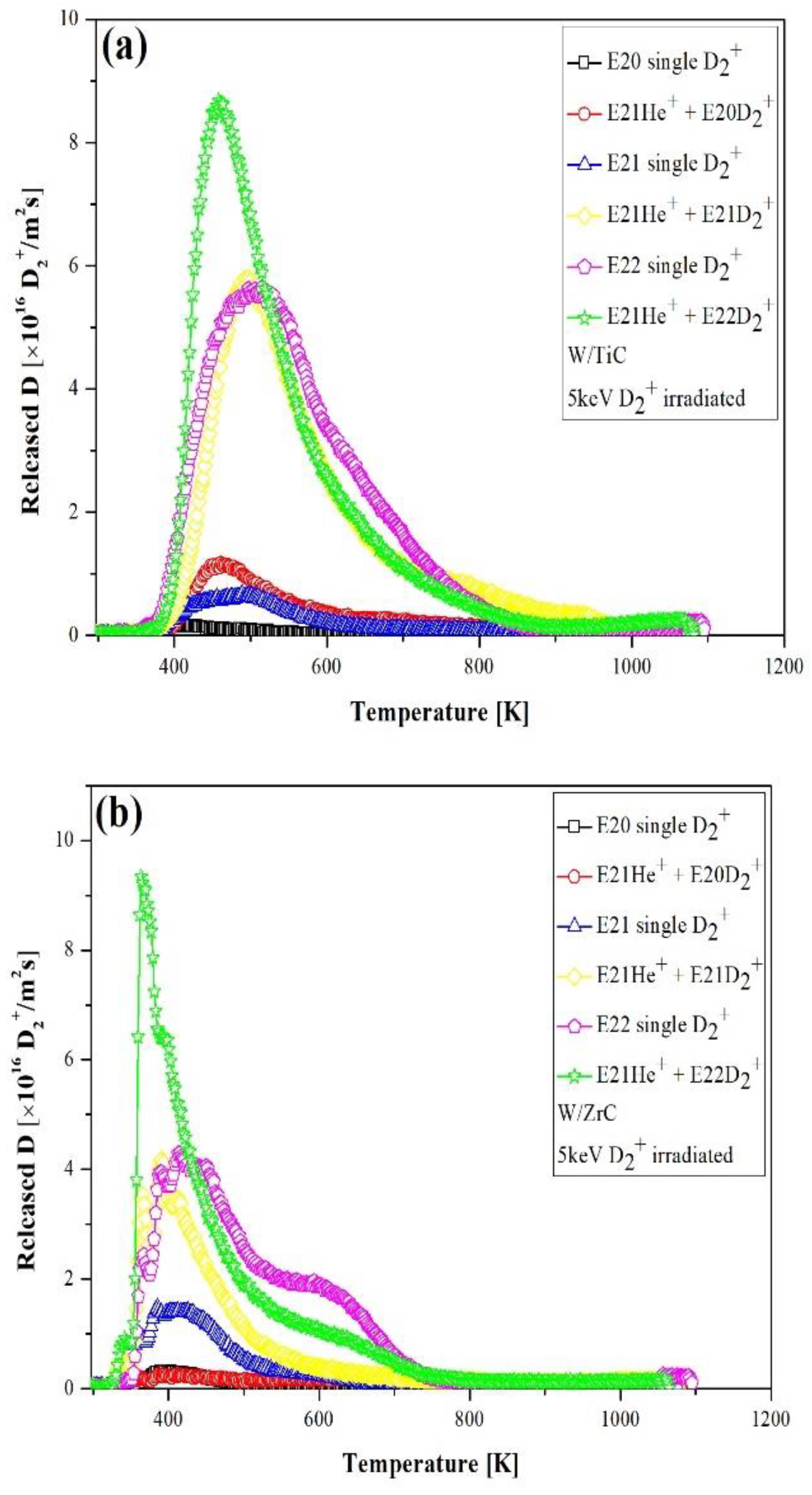
Following pre-irradiation of 5 keV He+ with the fluence of 1.0 × 10²¹ He+/m2, TDS measurement of deuterium implanted in the W-1wt%TiC and W-1wt%ZrC was performed. To illustrate directly the influence of He+ irradiation on D2 retention, deuterium ion irradiation at RT of 5 keV was performed subsequently at fluences of 1.0 × 10²⁰ D2+/m2, 1.0 × 10²¹ D2+/m2, and 1.0 × 10²² D2+/m2. Representative D2 desorption curves are plotted in Figure 9. The desorption of D2 from samples without He+ pre-irradiation is also given in the figure as a comparison. As shown in the figure, a single D2 desorption peak dominated the release in most of the studied cases. The peak in the spectra was detected in the temperature range of 400–600 K. However, a new high-temperature thermal desorption peak (or shoulders) appeared at about 600 K in W-1wt%ZrC as the irradiation fluence was increased to 1.0 × 10²² D2+/m2. There is no consensus on the understanding of the nature of the TDS desorption peaks in W alloys, because added particles may affect the number and positions of the desorption peaks. Based on the previous investigation, the low-temperature peaks in the TDS spectra for pure W are mainly attributed to deuterium release from some intrinsic defects of the W lattice (grain boundaries, dislocations). The high-temperature thermal desorption peaks (or shoulders) often correspond to deuterium release from ion-induced traps (vacancies, vacancies clusters, bubbles, and voids) [23].
The amount of D2 released from both samples increased with deuterium ion fluence. The irradiation by 5 keV D2+, well above the threshold for displacement damage of the order of 1 keV, can introduce damage by ion implantation itself in the implantation zone (equally as deep as the ion range). Dislocation loops and vacancy clusters were produced after D2+ irradiation. The densities and sizes of dislocation loops and vacancy clusters increased with increasing D2+ fluence. Hence, the amount of D2 released from dislocations at low temperature (with a low trapping energy) increased with D2+ irradiation dose. It was found that He+ pre-irradiation enhanced the low-temperature desorption peak, suggesting that the low-temperature peaks were related to the specific type of traps introduced by He+. The new D2 desorption peaks in W-1wt%ZrC occurred at higher temperature because of vacancy clusters (with a high trapping energy). These vacancy clusters were more easily produced in W-1wt%ZrC compared with W-1wt%TiC, indicating that W-1wt%TiC showed better radiation resistance to D2+.
The released deuterium from W is thermally activated de-trapping from the trapping sites and subsequently diffused to the W surface. The deuterium retention in W above 500 K is unlikely to saturate and increases with irradiation dose in the investigated fluence range [20,24], though the fluence dependence is indeterminate, either linear, square root, or in between. Therefore, it is necessary to clarify the mechanisms of deuterium retention in W.
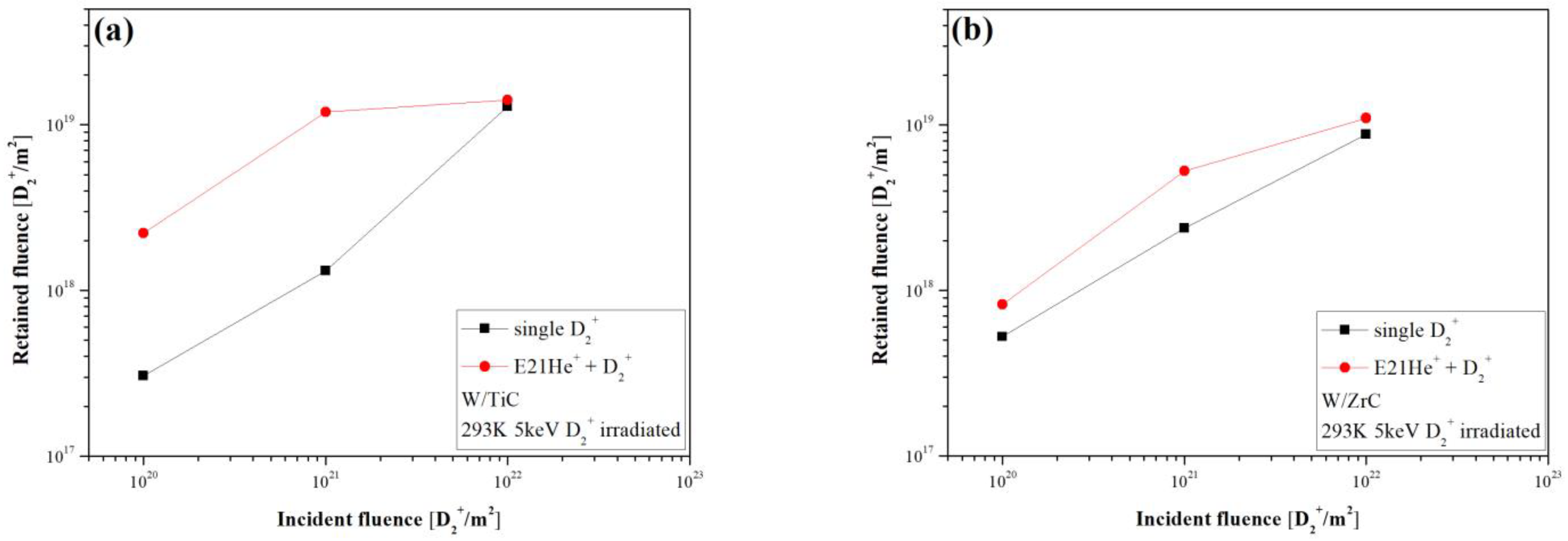
Figure 10a,b show the dependence of the total D2 retention on D2+ fluence in W-1wt%TiC and W-1wt%ZrC, respectively. When the fluence increased from 1.0 × 10²⁰ D2+/m2 to 1.0 × 10²² D2+/m2, D2 inventories increased for non-pre-irradiation cases, with no evidence of saturation. It has not yet been confirmed when D2 retention saturated in W-1wt%TiC and W-1wt%ZrC, due to the limited fluences covered in the study. As the fluence increased from 1.0 × 10²⁰ D2+/m2 to 1.0 × 10²² D2+/m2, the amount of D2 retained in W-1wt%TiC and W-1wt%ZrC after D2+ irradiation increased from 3.1 × 10¹⁷ D2+/m2 to 1.3 × 10¹⁹ D2+/m2, and from 5.3 × 10¹⁷ D2+/m2 to 8.8 × 10¹⁸ D2+/m2, respectively. The D2 inventories did not follow a proportional relationship with the root of the exposure time, i.e., not like the ideal case of diffusion-limited retention.
Compared with pure polycrystalline W, carbide-doped W materials exhibit a tendency to retain more deuterium at high temperatures (>450 K) [25], which can be attributed to the carbide precipitates. One the one hand, transition-metal carbides are non-stoichiometric (i.e., TiCx, or ZrCx), and contain vacant sites in the carbon sublattice that could effectively trap H isotopes [26]. On the other hand, TiC (or ZrC)-particle-doped W can suppress the formation of substantial defects during the ion irradiation process by providing a large number of defect sinks to absorb microstructure defects induced by ion irradiation. The volume concentrations of carbides in W-1wt%TiC and W-1wt%ZrC are about 3 at. % and 1.6 at. %, respectively, thus providing a high concentration of deuterium trapping sites. The differences in the size and number of the carbides, their stoichiometry, and their deuterium diffusivity should play a vital role in determining the difference in D2 retention in W-1wt%TiC and W-1wt%ZrC.
The D2 retention of W-1wt%TiC and W-1wt%ZrC after He+ pre-irradiation increased compared to that of samples without He+ pre-irradiation, which may be caused by the increase in trapping sites introduced by He+ bombardment. The difference in inventory in W-1wt%ZrC was small in contrast to W-1wt%TiC as D2+ fluence increased from 1.0 × 10²⁰ D2+/m2 to 1.0 × 10²¹ D2+/m2. When the D2+ fluence was 1.0 × 10²² D2+/m2, the total retention difference in both samples became even smaller, suggesting that the capture sites introduced by the He+ irradiation were close to saturation by trapping injected deuterium.

4. Conclusions

W doped either with titanium carbide (W-1wt%TiC) or zirconium carbide (W-1wt%ZrC) was synthesized by a wet chemical method and SPS technique. TiC and ZrC particles displayed good dispersibility into the W matrix. The average grain sizes of the sintered W-1wt%TiC and W-1wt%ZrC were about 3 μm. The relative density of W-1wt%TiC was 98.6% was higher than W-1wt%ZrC with 97.2%. The thermal conductivity of W-1wt%ZrC was slightly lower than that of W-1wt%TiC. However, the thermal conductivity values for both samples were above 110 W/m·K at RT.
Exposure at 600 °C with 5 keV He+ led to the appearance of many dislocation loops, which grew quickly and tangled with each other with increasing irradiation fluences. The number densities of W-1wt%TiC were 4.1 × 10²³, which was higher than W-1wt%ZrC with 3.0 × 10²², but the loop size of the W-1wt%TiC was 2.1 nm, on average smaller than W-1wt%ZrC with 12.8 nm. He bubbles were not observed throughout in both types of carbide-doped W, indicating that carbide doping could increase the interfacial area between the W matrix and carbide particles to absorb interstitials and vacancies, thus enhancing the radiation tolerance of W to He+ ions.
The D2 inventories in W-1wt%TiC and W-1wt%ZrC did not follow a proportional relationship with the root of the exposure time, i.e., not like the ideal case of diffusion-limited retention. Under the present exposure condition, the deuterium inventories increased for samples without He+ pre-irradiation, with no evidence of saturation. The irradiation effect of He+ ions also strongly influenced the deuterium retention. Compared with non-pre-irradiation cases, deuterium retention in carbide-doped W increased after He+ pre-irradiation, owning to the increase in trapping sites caused by He+ bombardment.

Author Contributions

Methodology, Q.X.; formal analysis, L.L.; investigation, P.Z. and H.Z.; data curation, J.F.; writing-original draft preparation, X.D.; supervision, J.Y.; writing-review and editing, funding acquisition, Y.W. All authors have read and agreed to the published version of the manuscript.

Funding

This work was funded by the Fundamental Research Funds for the Central Universities (PA2021GDSK0090), the National Natural Science Foundation of China (Grant No. 52105311), and partly funded by JSPS KAKENHI (Grant No. JP20K03900).

Data Availability Statement

The raw/processed data required to reproduce these findings cannot be shared at this time as the data also form part of an ongoing study.

Conflicts of Interest

The authors declare that they have no known competing financial interest or personal relationships that could have appeared to influence the work reported in this paper.

References

  1. Sandoval, L.; Perez, D.; Uberuaga, B.P.; Voter, A.F. Formation of helium-bubble networks in tungsten. Acta Mater. 2018, 159, 46–50. [Google Scholar] [CrossRef]
  2. El-Atwani, O.; Esquivel, E.; Efe, M.; Aydogan, E.; Wang, Y.Q.; Martinez, E.; Maloy, S.A. Loop and void damage during heavy ion irradiation on nanocrystalline and coarse grained tungsten: Microstructure, effect of dpa rate, temperature, and grain size. Acta Mater. 2018, 149, 206–219. [Google Scholar] [CrossRef]
  3. Frolov, T.; Zhu, Q.; Oppelstrup, T.; Marian, J.; Rudd, R.E. Structures and transitions in bcc tungsten grain boundaries and their role in the absorption of point defects. Acta Mater. 2018, 159, 123–134. [Google Scholar] [CrossRef]
  4. Qin, W.J.; Ren, F.; Doerner, R.P.; Wei, G.; Lv, Y.W.; Chang, S.; Tang, M.; Deng, H.Q.; Jiang, C.Z.; Wang, Y.Q. Nanochannel structures in W enhance radiation tolerance. Acta Mater. 2018, 153, 147–155. [Google Scholar] [CrossRef]
  5. El-Atwani, O.; Gonderman, S.; Efe, M.; De Temmerman, G.; Morgan, T.; Bystrov, K.; Klenosky, D.; Qiu, T.; Allain, J.P. Ultrafine tungsten as a plasma-facing component in fusion devices: Effect of high flux, high fluence low energy helium irradiation. Nucl. Fusion 2014, 54, 083013. [Google Scholar] [CrossRef]
  6. Zhao, M.; Jacob, W.; Manhard, A.; Gao, L.; Balden, M.; von Toussaint, U.; Zhou, Z. Deuterium implantation into Y2O3-doped and pure tungsten: Deuterium retention and blistering behavior. J. Nucl. Mater. 2017, 487, 75–83. [Google Scholar] [CrossRef]
  7. Xia, M.; Yan, Q.Z.; Guo, H.Y.; Zhu, L.X.; Ge, C.C. Bulk tungsten with uniformly dispersed La2O3 nanoparticles sintered from co-precipitated La2O3/W nanoparticles. J. Nucl. Mater. 2013, 434, 85–89. [Google Scholar] [CrossRef]
  8. Xia, M.; Yan, Q.Z.; Xu, L.; Zhu, L.X.; Guo, H.Y.; Ge, C.C. Synthesis of TiC/W core–shell nanoparticles by precipitate-coating process. J. Nucl. Mater. 2012, 430, 216–220. [Google Scholar] [CrossRef]
  9. Ding, H.L.; Xie, Z.M.; Fang, Q.F.; Zhang, T.; Cheng, Z.J.; Zhuang, Z.; Wang, X.P.; Liu, C.S. Determination of the DBTT of nanoscale ZrC doped W alloys through amplitude-dependent internal friction technique. Mat. Sci. Eng. A 2018, 716, 268–273. [Google Scholar] [CrossRef]
  10. Wang, Y.K.; Miao, S.; Xie, Z.M.; Liu, R.; Zhang, T.; Fang, Q.F.; Hao, T.; Wang, X.P.; Liu, C.S.; Liu, X.; et al. Thermal stability and mechanical properties of HfC dispersion strengthened W alloys as plasma-facing components in fusion devices. J. Nucl. Mater. 2017, 492, 260–268. [Google Scholar] [CrossRef]
  11. Tanabe, T. Review of hydrogen retention in tungsten. Phys. Scr. 2014, T159, 014044. [Google Scholar] [CrossRef]
  12. Arkhipov, I.I.; Kanashenko, S.L.; Sharapov, V.M.; Zalavutdinov, R.K.; Gorodetsky, A.E. Deuterium trapping in ion-damaged tungsten single crystal. J. Nucl. Mater. 2007, 363–365, 1168–1172. [Google Scholar] [CrossRef]
  13. Iwakiri, H.; Yasunaga, K.; Morishita, K.; Yoshida, N. Microstructure evolution in tungsten during low-energy helium ion irradiation. J. Nucl. Mater. 2000, 283–287, 1134–1138. [Google Scholar] [CrossRef]
  14. Iwakiri, H.; Morishita, K.; Yoshida, N. Effects of helium bombardment on the deuterium behavior in tungsten. J. Nucl. Mater. 2002, 307–311, 135–138. [Google Scholar] [CrossRef]
  15. Yi, X.; Jenkins, M.L.; Kirk, M.A.; Zhou, Z.; Roberts, S.G. In-situ TEM studies of 150 keV W+ ion irradiated W and W-alloys: Damage production and microstructural evolution. Acta Mater. 2016, 112, 105–120. [Google Scholar] [CrossRef]
  16. Xu, Q.; Ding, X.Y.; Luo, L.M.; Miyamoto, M.; Tokitani, M.; Zhang, J.; Wu, Y.C. D2 retention and microstructural evolution during He irradiation in candidate plasma facing material W–La2O3 alloy. J. Nucl. Mater. 2017, 496, 227–233. [Google Scholar] [CrossRef]
  17. Daghbouj, N.; Sen, H.S.; Čížek, J.; Lorinčík, J.; Karlík, M.; Callisti, M.; Čech, J.; Havránek, V.; Li, B.; Krsjak, V.; et al. Characterizing heavy ions-irradiated Zr/Nb: Structure and mechanical properties. Mater. Design. 2022, 219, 110732. [Google Scholar] [CrossRef]
  18. Daghbouj, N.; Sen, H.S.; Callisti, M.; Vronka, M.; Karlik, M.; Duchon, J.; Čech, J.; Havránek, V.; Polcar, T. Revealing nanoscale strain mechanisms in ion-irradiated multilayers. Acta Mater. 2022, 229, 117807. [Google Scholar] [CrossRef]
  19. Watanabe, H.; Futagami, N.; Naitou, S.; Yoshida, N. Microstructure and thermal desorption of deuterium in heavy-ion-irradiated pure tungsten. J. Nucl. Mater. 2014, 455, 51–55. [Google Scholar] [CrossRef]
  20. Roth, J.; Schmid, K. Hydrogen in tungsten as plasma-facing material. Phys. Scr. 2011, T159, 014031. [Google Scholar] [CrossRef]
  21. Zibrov, M.; Mayer, M.; Markina, E.; Sugiyama, K.; Betzenbichler, M.; Kurishita, H.; Gasparyan, Y.; Ogorodnikova, O.V.; Manhard, A.; Pisarev, A. Deuterium retention in TiC and TaC doped tungsten under low-energy ion irradiation. Phys. Scr. 2014, T159, 14050. [Google Scholar] [CrossRef]
  22. Lee, H.T.; Haasz, A.A.; Davis, J.W.; Macaulay-Newcombe, R.G.; Whyte, D.G.; Wright, G.M. Hydrogen and helium trapping in tungsten under simultaneous irradiations. J. Nucl. Mater. 2007, 363–365, 898–903. [Google Scholar] [CrossRef]
  23. Ogorodnikova, O.V.; Roth, J.; Mayer, M. Deuterium retention in tungsten in dependence of the surface conditions. J. Nucl. Mater. 2003, 313–316, 469–477. [Google Scholar] [CrossRef]
  24. Tian, Z.; Davis, J.W.; Haasz, A.A. Deuterium retention in tungsten at fluences of up to 1026 D+/m2 using D+ ion beams. J. Nucl. Mater. 2010, 399, 101–107. [Google Scholar] [CrossRef]
  25. Oya, M.; Lee, H.T.; Ohtsuka, Y.; Ueda, Y.; Kurishita, H.; Oyaidzu, M.; Yamanishi, T. Deuterium retention in various toughened, fine-grained recrystallized tungsten materials under different irradiation conditions. Phys. Scripta 2014, T159, 014048. [Google Scholar] [CrossRef]
  26. Zibrov, M.; Bystrov, K.; Mayer, M.; Morgan, T.W.; Kurishita, H. The high-flux effect on deuterium retention in TiC and TaC doped tungsten at high temperatures. J. Nucl. Mater. 2017, 494, 211–218. [Google Scholar] [CrossRef]
Figure 1. SEM micrographs showing surface morphology of reduced powder: (a) W-1wt%TiC, (b) W-1wt%ZiC.
Metals 13 00783 g001
Figure 2. SEM micrographs showing the polished and etched surfaces of (a) W-1wt%TiC, (b) W-1wt%ZrC.
Metals 13 00783 g002
Figure 3. Phase identification for the SPS-sintered W-1wt%TiC and W-1wt%ZrC.
Metals 13 00783 g003
Figure 4. SEM images showing fracture surface morphology of (a) W-1wt%TiC, (b) W-1wt%ZrC.
Metals 13 00783 g004
Figure 5. TEM images showing the microstructure of unirradiated samples: (a) W-1wt%TiC, (b) W-1wt%ZrC.
Metals 13 00783 g005
Figure 6. TEM images showing the microstructural evolution in pure W exposed to 5 keV He+ as a function of fluence: (a) 1.0 × 10²⁰ He+/m2; (b) 1.0 × 10²¹ He+/m2; (c) 5.0 × 10²¹ He+/m2.
Metals 13 00783 g006
Figure 7. TEM images showing the microstructural evolution in W-1wt%TiC exposed to 5 keV He+ as a function of fluence: (a) 1.0 × 10²⁰ He+/m2; (b) 1.0 × 10²¹ He+/m2; (c) 5.0 × 10²¹ He+/m2.
Metals 13 00783 g007
Figure 8. TEM images showing the microstructural evolution in W-1wt%ZrC exposed to 5 keV He+ as a function of fluence: (a) 1.0 × 10²⁰ He+/m2; (b) 1.0 × 10²¹ He+/m2; (c) 5.0 × 10²¹ He+/m2.
Metals 13 00783 g008
Figure 9. D2 TDS spectra as a function of temperature in both materials type implanted with various fluences of D2+ ions after pre-irradiation by 5 keV 1.0 × 10²¹ He+/m2 at RT: (a) W-1wt%TiC, (b) W-1wt%ZrC.
Metals 13 00783 g009
Figure 10. Retained deuterium amount for both material types as a function of fluences of D2+ ion implantation after pre-irradiation by 5 keV 1.0 × 10²¹ He+/m2 at RT: (a) W-1wt%TiC, (b) W-1wt%ZrC.
Metals 13 00783 g010
Table 1. Relative density, grain size, microhardness, and thermal conductivity at RT of W-1wt%TiC and W-1wt%ZrC sintered by SPS.
SampleRelative Density (%)Grain Size (μm)HV200gThermal Conductivity at RT (W/m·K)
W-1wt%TiC98.63471127
W-1wt%ZrC97.23427110
Table 2. Information on the loop number volume density and mean dislocation loop diameter of W-1wt%TiC and W-1wt%ZrC implanted at 600 °C with 5 keV He+ at the fluence of 1.0 × 10²⁰ He+/m2.
SampleLoop-Number Volume Density (Loops/m3)Mean Dislocation Loop Diameter (nm)
W-1wt%TiC4.1 × 10232.1
W-1wt%ZrC3.0 × 102212.8
Disclaimer/Publisher’s Note: The statements, opinions and data contained in all publications are solely those of the individual author(s) and contributor(s) and not of MDPI and/or the editor(s). MDPI and/or the editor(s) disclaim responsibility for any injury to people or property resulting from any ideas, methods, instructions or products referred to in the content.