
Research on the Electric-Pulse-Assisted Turning Behavior of TC27 Alloy

Abstract
:1. Introduction
2. Experimental Procedure
2.1. Materials and Cutting Tool
2.2. Machining Experiment
2.3. Characterization of the Experiment
3. Results and Discussion
3.1. Effect of Electric Pulses on the Cutting Performance of the Titanium Alloy
3.1.1. Cutting Force
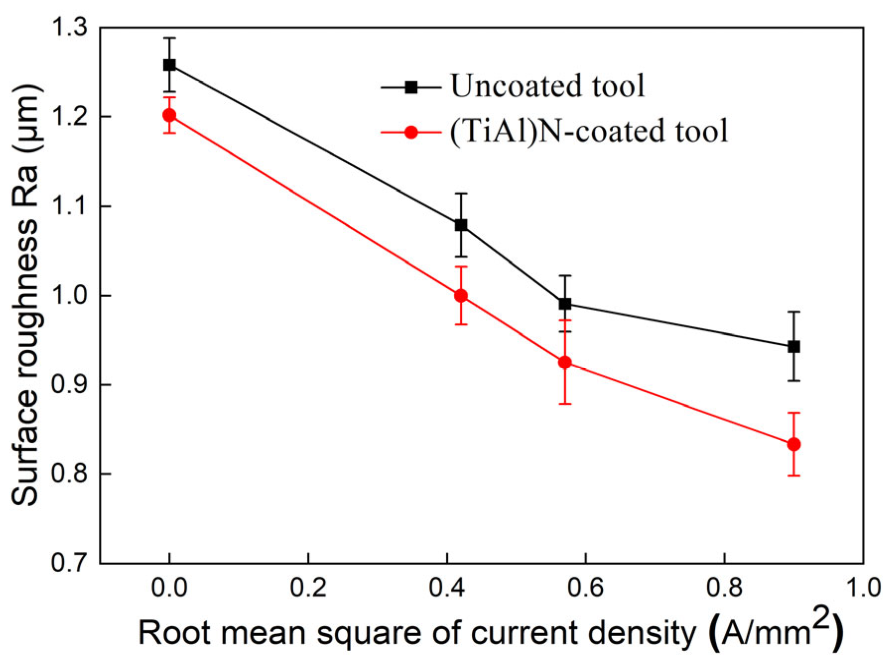
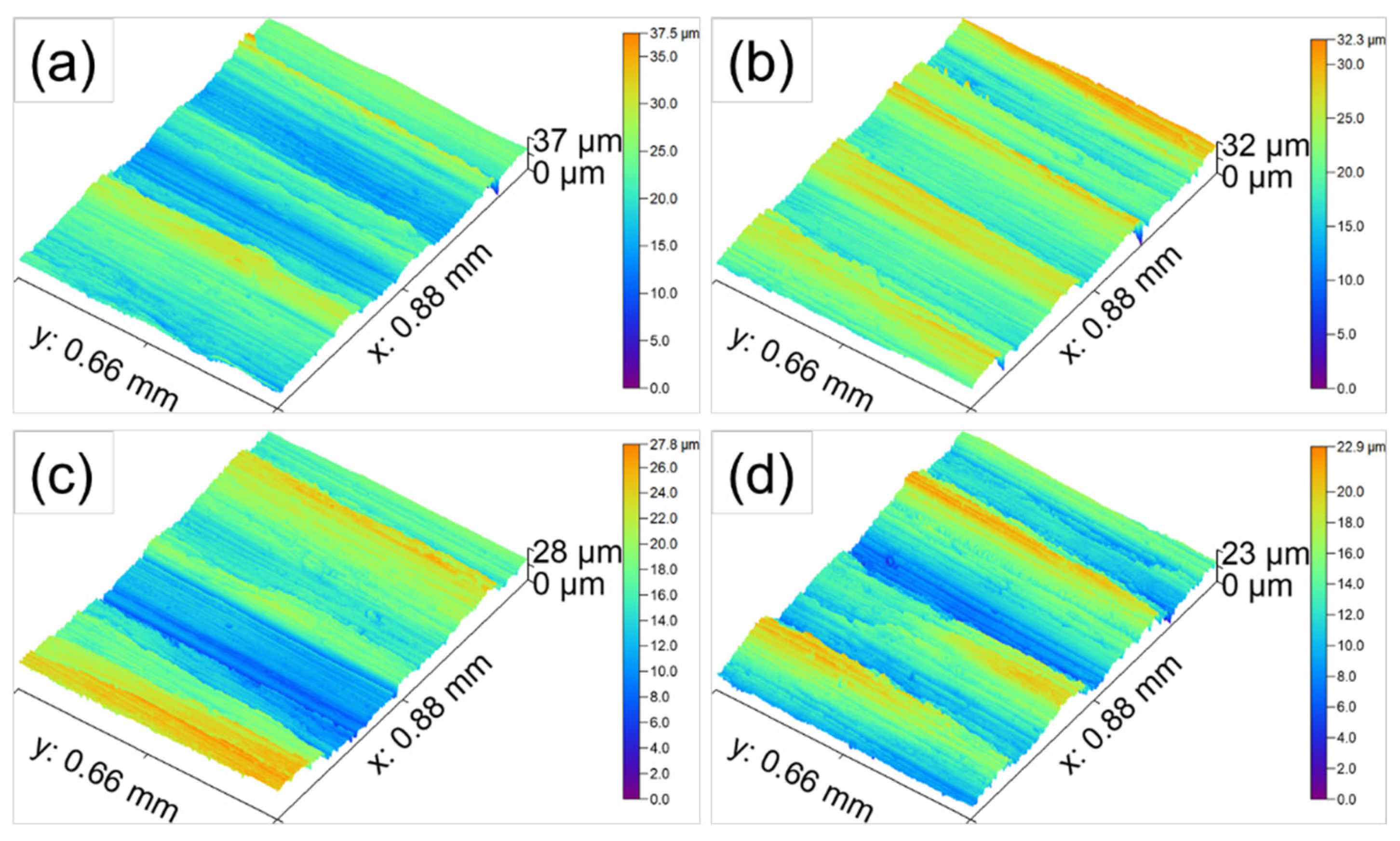
3.1.2. Surface Roughness
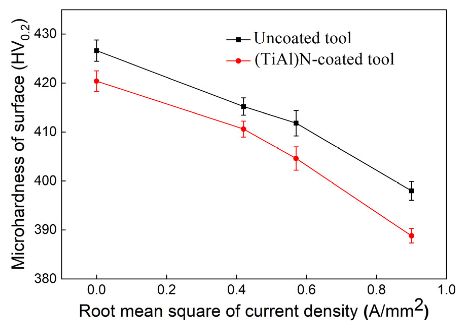
3.1.3. Surface Work Hardening
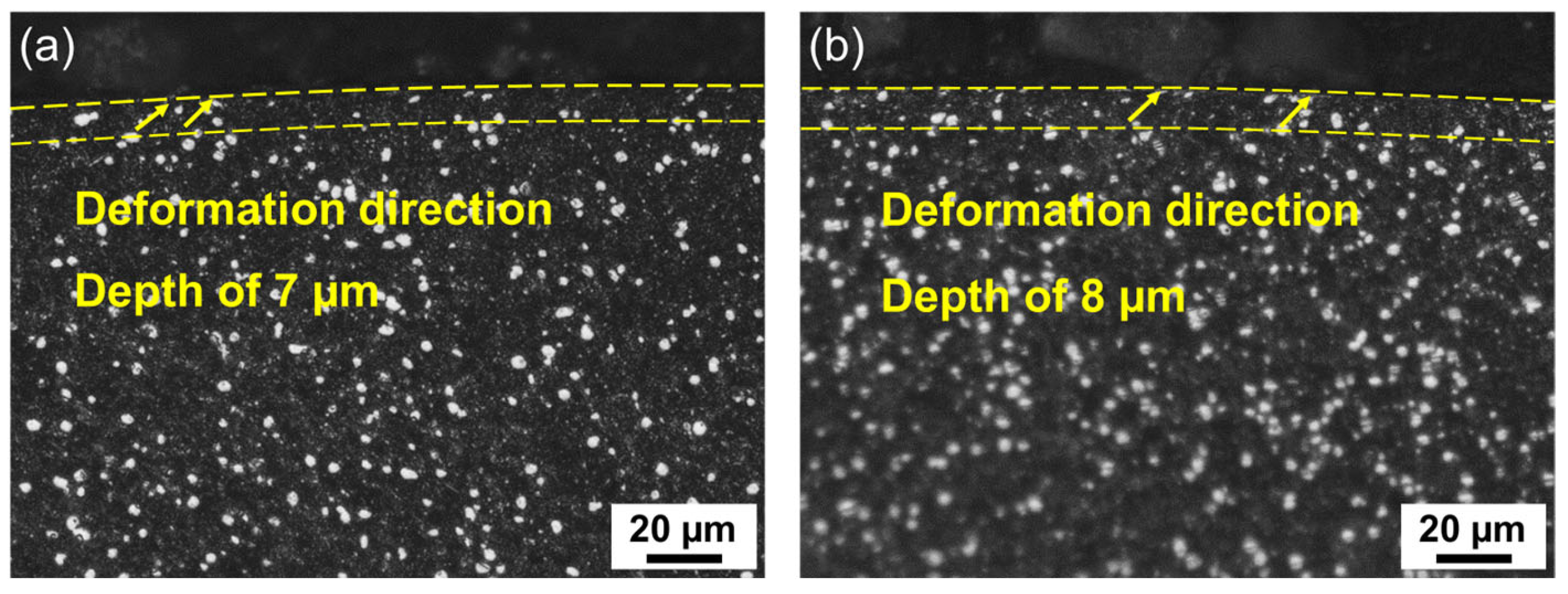
3.2. Cross-Section Microstructure of the Workpiece
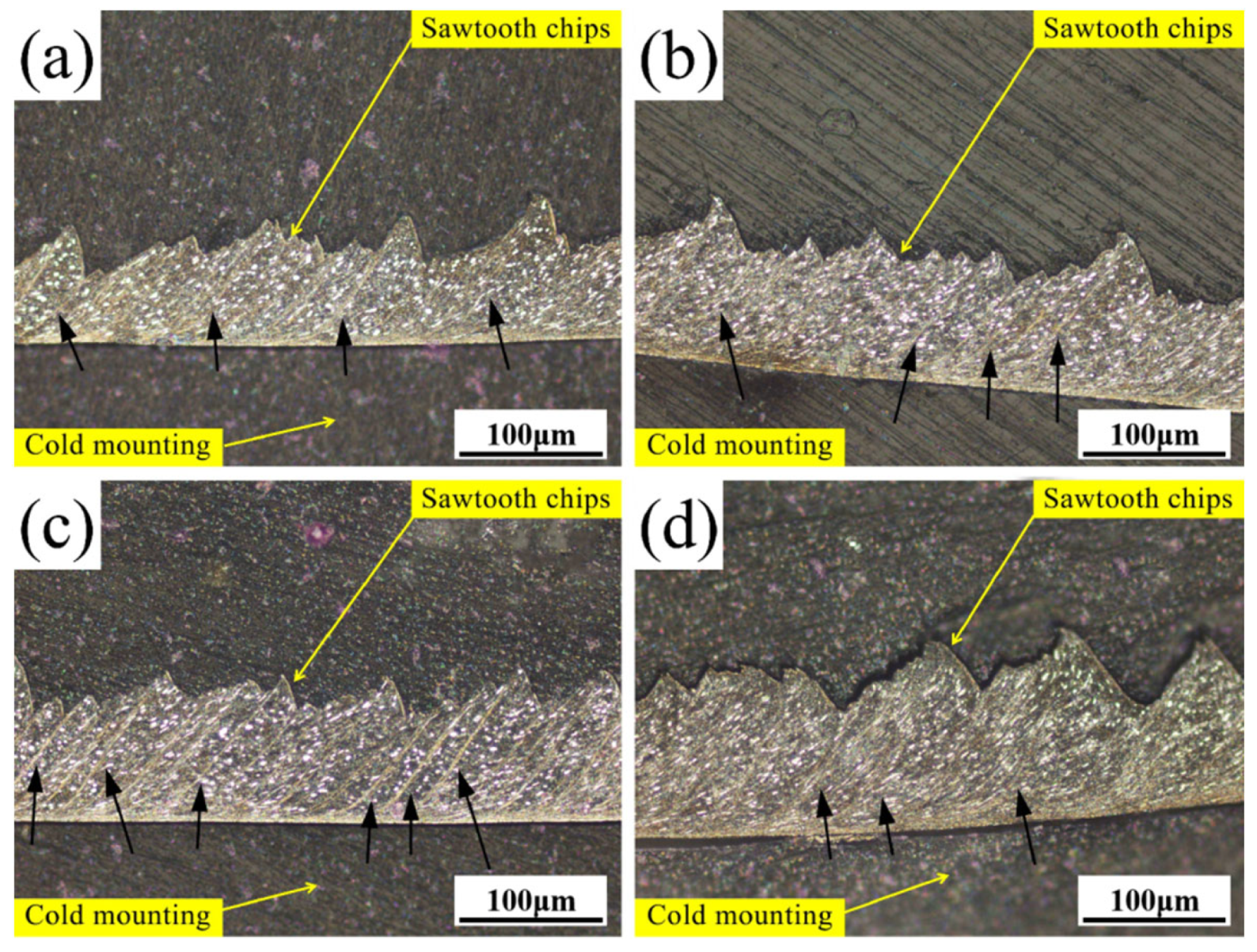
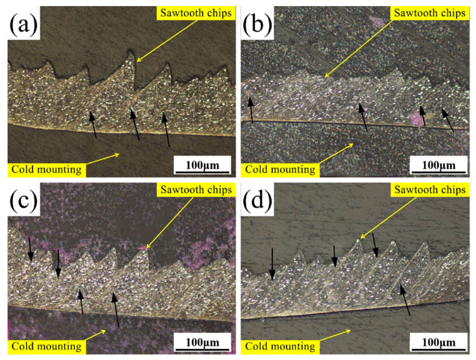
3.3. Morphology of the Chips
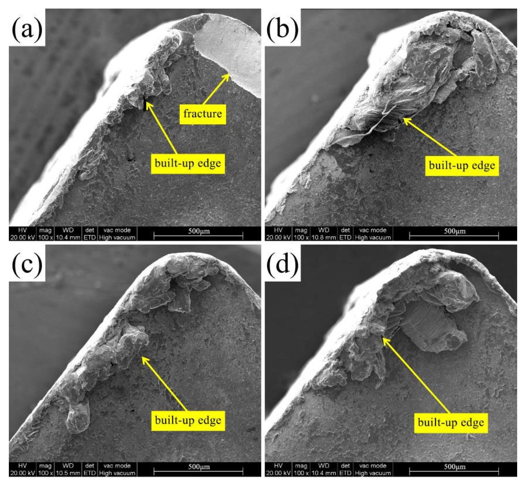
3.4. Wear Mechanisms of the Tool
3.4.1. Flank Face Wear
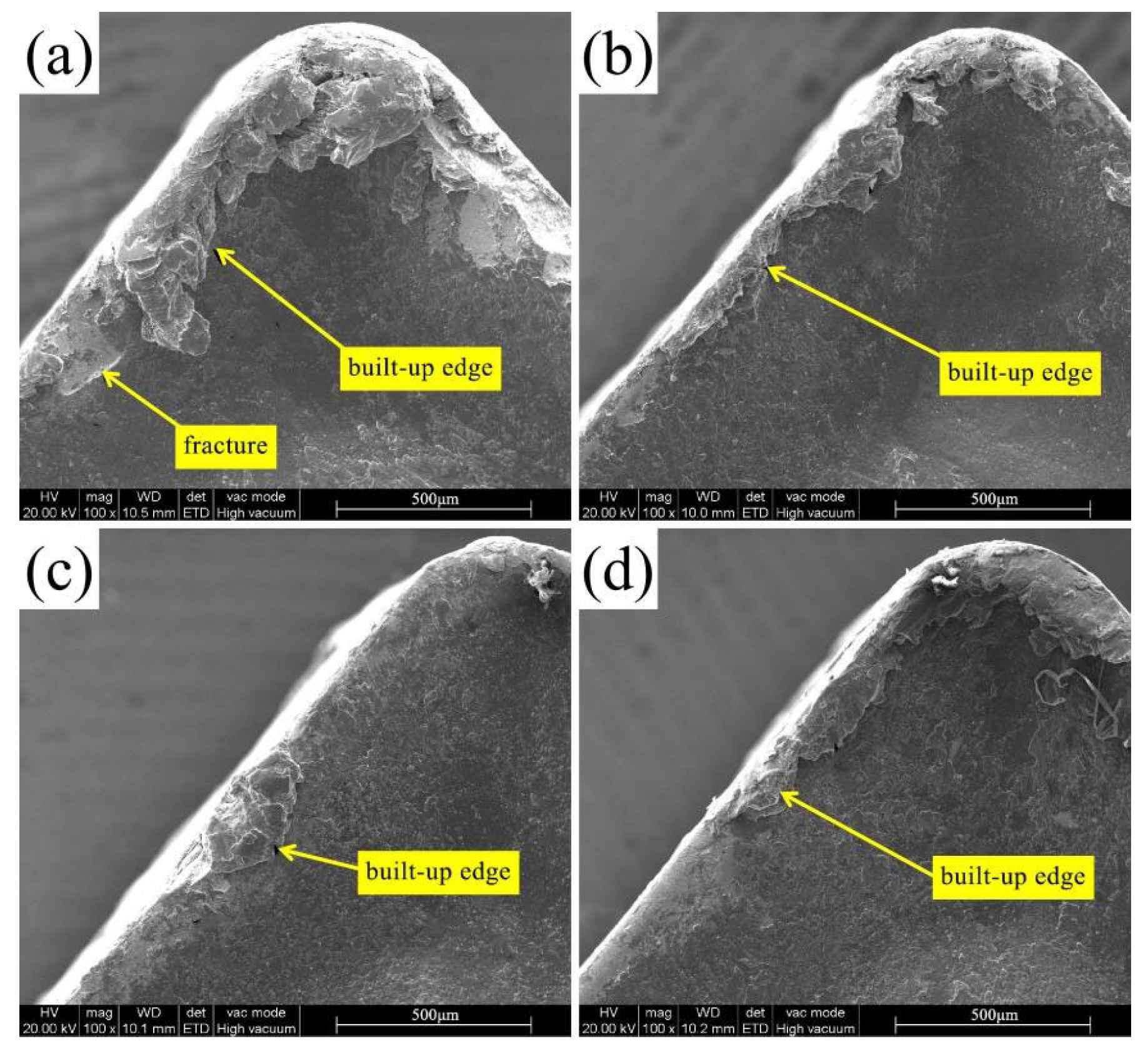
3.4.2. Rake Face Wear
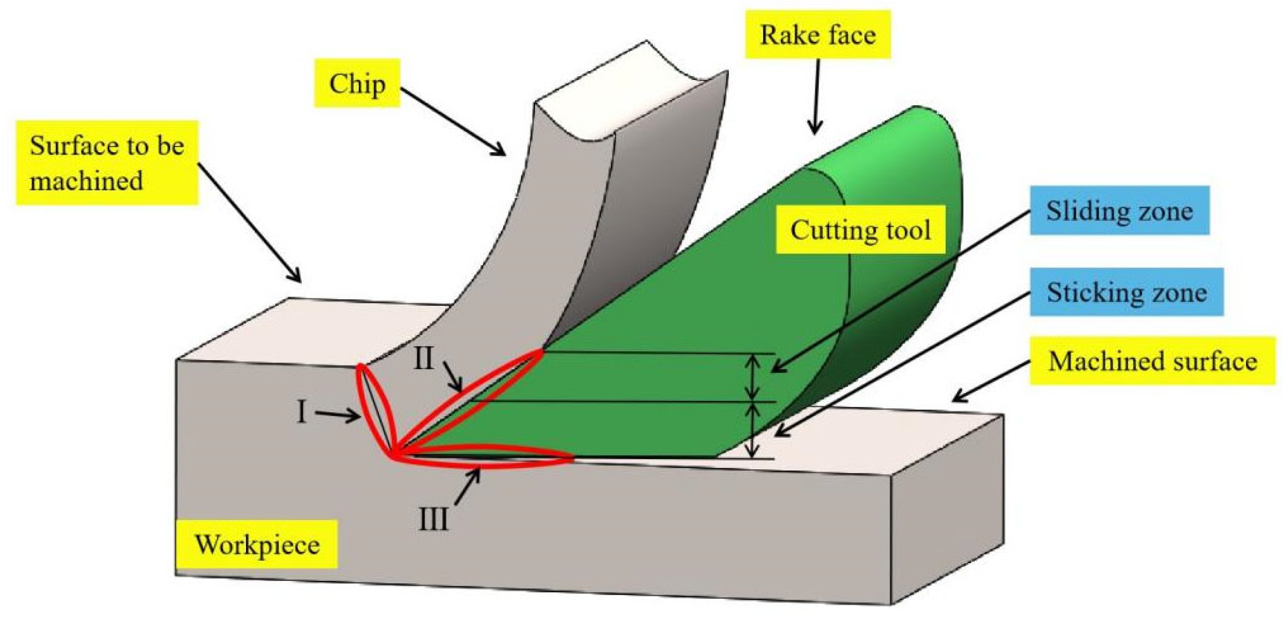
3.4.3. The Pulse Current Improves the Friction State between the Chip and the Tool
4. Conclusions
Author Contributions
Funding
Institutional Review Board Statement
Data Availability Statement
Acknowledgments
Conflicts of Interest
Nomenclature
| EPT | electric-pulse-assisted turning |
| CT | conventional turning |
| CCI | TiAlN-coated cemented carbide insert |
| UCI | uncoated carbide insert |
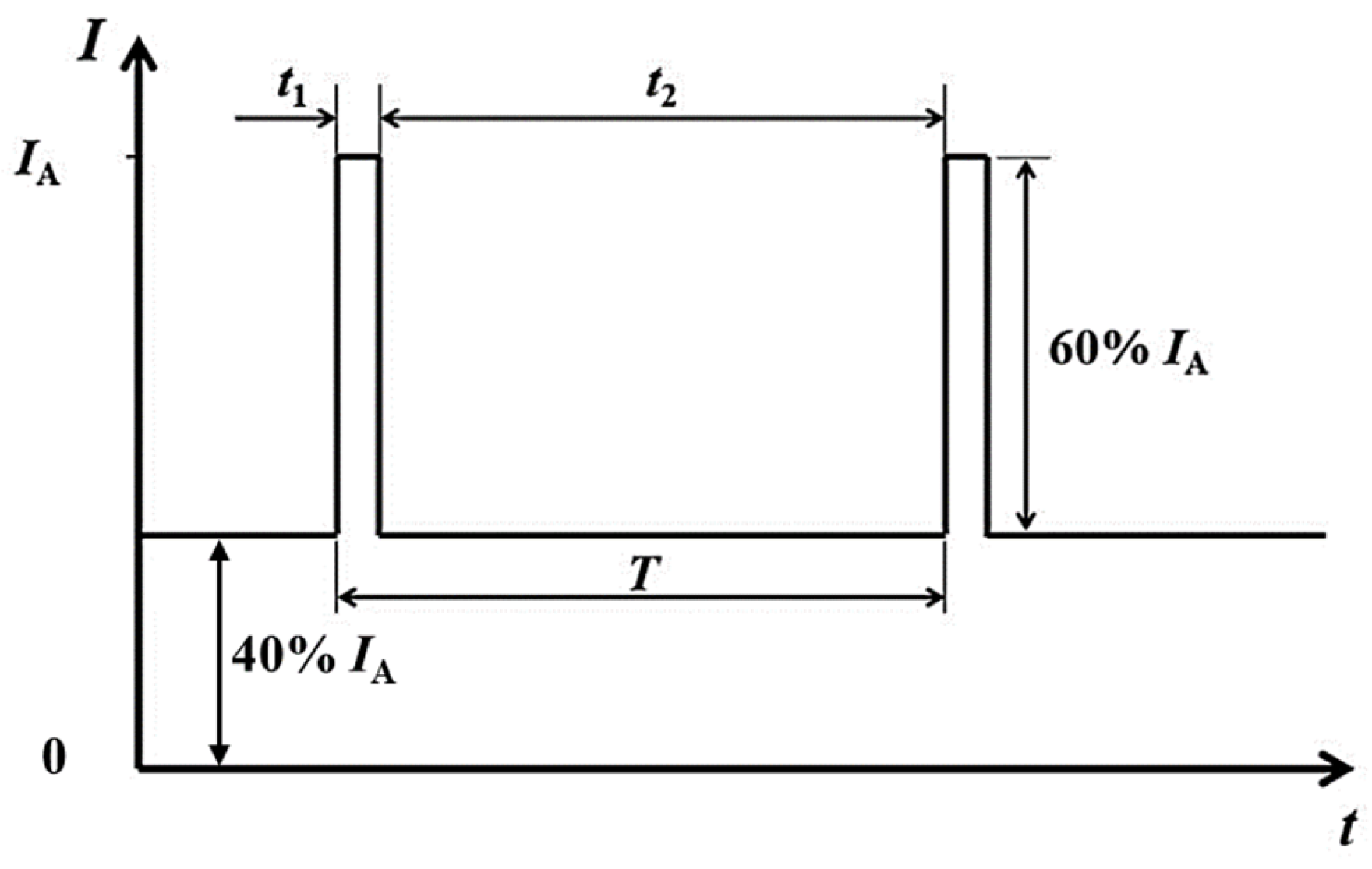
| t1 | pulse on time |
| t2 | pulse off time |
| T | pulse period |
| IA | peak current |
| S | cross-sectional area of the workpiece |
| Ft | tangential force |
| TC27 | Ti5Al4Mo6V2Nb1Fe |
| Ra | Roughness of surface |
References
- Ellyson, B.; Brochu, M.; Brochu, M. Characterization of bending vibration fatigue of SLM fabricated Ti-6Al-4V. Int. J. Fatigue 2017, 99, 25–34. [Google Scholar] [CrossRef]
- Joyson, S.S.; Sakthivel, P.; Jerome, A.P.; Samuel, R.D. Effect of edge radius on forces, tool wear and surface integrity under edge radius dominated tool-chip contact conditions. Proc. Inst. Mech. Eng. Part B J. Eng. Manuf. 2023. [Google Scholar] [CrossRef]
- Umbrello, D. Finite element simulation of conventional and high speed machining of Ti6Al4V alloy. J. Mater. Process. Technol. 2008, 196, 79–87. [Google Scholar] [CrossRef]
- Shokrani, A.; Dhokia, V.; Newman, S. Investigation of the effects of cryogenic machining on surface integrity in CNC end milling of Ti–6Al–4V titanium alloy. J. Manuf. Process. 2016, 21, 172–179. [Google Scholar] [CrossRef] [Green Version]
- Ruggiero, A.; D’amato, R.; Gómez, E.; Merola, M. Experimental comparison on tribological pairs UHMWPE/TIAL6V4 alloy, UHMWPE/AISI316L austenitic stainless and UHMWPE/AL2O3 ceramic, under dry and lubricated conditions. Tribol. Int. 2016, 96, 349–360. [Google Scholar] [CrossRef]
- Bai, D.; Sun, J.; Chen, W.; Wang, T. Wear mechanisms of WC/Co tools when machining high-strength titanium alloy TB6 (Ti-10V-2Fe-3Al). Int. J. Adv. Manuf. Technol. 2016, 90, 2863–2874. [Google Scholar] [CrossRef]
- Sharma, A.; Sharma, M.D.; Sehgal, R. Experimental Study of Machining Characteristics of Titanium Alloy (Ti–6Al–4V). Arab. J. Sci. Eng. 2012, 38, 3201–3209. [Google Scholar] [CrossRef]
- Sartori, S.; Moro, L.; Ghiotti, A.; Bruschi, S. On the tool wear mechanisms in dry and cryogenic turning Additive Manufactured titanium alloys. Tribol. Int. 2017, 105, 264–273. [Google Scholar] [CrossRef]
- Masek, P.; Maly, J.; Zeman, P.; Heinrich, P.; Alagan, N.T. Turning of titanium alloy with PCD tool and high-pressure cooling. J. Manuf. Process. 2022, 84, 871–885. [Google Scholar] [CrossRef]
- Troitskii, O.A.; Likhtman, V.I. The anisotropy of the action of electron and gamma radiation on the deformation of zinc single crystal in the brittle state. Sov. Phys. Dokl. 1963, 8, 91–93. [Google Scholar]
- Conrad, H. Electroplasticity in metals and ceramics. Mater. Sci. Eng. A 2000, 287, 276–287. [Google Scholar] [CrossRef]
- Conrad, H.; Sprecher, A.F.; Cao, W.D.; Lu, X.P. Electroplasticity—The effect of electricity on the mechanical properties of metals. JOM 1990, 42, 28–33. [Google Scholar] [CrossRef]
- Conrad, H. Thermally activated plastic flow of metals and ceramics with an electric field or current. Mater. Sci. Eng. A 2002, 322, 100–107. [Google Scholar] [CrossRef]
- Hameed, S.; Hernan, A.; Rojas, G. Electroplastic cutting influence on powder consumption during drilling process. Int. J. Adv. Manuf. Technol. 2016, 87, 1835–1841. [Google Scholar] [CrossRef] [Green Version]
- Egea, A.J.S.; Rojas, H.A.G.; Montaña, C.A.M.; Echeverri, V.K. Effect of electroplastic cutting on the manufacturing process and surface properties. J. Mater. Process. Technol. 2015, 222, 327–334. [Google Scholar] [CrossRef]
- Wang, H.; Chen, L.; Liu, D.; Song, G.; Tang, G. Study on electropulsing assisted turning process for AISI 304 stainless steel. Mater. Sci. Technol. 2015, 31, 1564–1571. [Google Scholar] [CrossRef]
- Ghiotti, A.; Bruschi, S.; Simonetto, E.; Gennari, C.; Calliari, I.; Bariani, P. Electroplastic effect on AA1050 aluminium alloy formability. CIRP Ann. 2018, 67, 289–292. [Google Scholar] [CrossRef]
- Sun, J.; Guo, B. A new multi-view approach to characterize 3D chip morphology and properties in end milling titanium Ti-6Al-4V. Int. J. Mach. Tools Manuf. 2008, 48, 1486–1494. [Google Scholar] [CrossRef]
- Xu, X.; Zhao, Y.; Wang, X.; Zhang, Y.; Ning, Y. Effect of rapid solid-solution induced by electropulsing on the microstructure and mechanical properties in 7075 Al alloy. Mater. Sci. Eng. A 2016, 654, 278–281. [Google Scholar] [CrossRef]
- Ren, Z.J.; Qu, S.G.; Zhang, Y.L.; Li, X.Q.; Yang, C. Machining Performance of TiAlN-Coated Cemented Carbide Tools with Chip Groove in Machining Titanium Alloy Ti-6Al-0.6Cr-0.4Fe-0.4Si-0.01B. Metals 2018, 8, 850. [Google Scholar] [CrossRef] [Green Version]
- Lima, G.D.; Nascimento, B.L.; de Souza Alves Júnio, I.; Trindade, M.P.; Griza, S. Fatigue behavior and life predictions of thermally oxidized Ti6Al4V alloy according to oxidation parameters. Eng. Fail. Anal. 2021, 130, 105737. [Google Scholar] [CrossRef]
- Ao, D. Study on Electric Pulse Assisted Single Point Incremental Forming of Ti6Al4V Titanium Alloy Sheet. Ph.D. Thesis, Shandong University, Jinan, China, 2019. (In Chinese). [Google Scholar]
- Li, R.; Shih, A. Finite element modeling of 3D turning of titanium. Int. J. Adv. Manuf. Technol. 2006, 29, 253–261. [Google Scholar] [CrossRef] [Green Version]
- Palanikumar, S.R.; Boppana, K.; Boppana, S.B.; Natarajian, E. Analysis of Chip Formation and Temperature Measurement in Machining of Titanium Alloy (Ti-6Al-4V). Exp. Tech. 2023, 47, 517–519. [Google Scholar] [CrossRef]
- Wang, L. Simulation Analysis and Experimental Research on Laser Heating-Assisted Turning of Titanium Alloy Ti6Al4V. Master’s Thesis, Harbin Institute of Technology, Harbin, China, 2016. (In Chinese). [Google Scholar]
- Komanduri, R.; Von Turkovich, B. New observations on the mechanism of chip formation when machining titanium alloys. Wear 1981, 69, 179–188. [Google Scholar] [CrossRef]
- Stolyarov, V.V. Deformability and nanostructuring of TiNi shape-memory alloys during electroplastic rolling. Mater. Sci. Eng. A 2009, 503, 18–20. [Google Scholar] [CrossRef]
- Sánchez-Egea, A.; González-Rojas, H.; Montilla-Montaña, C.; Kallewaard-Echeverri, V. Turning Process Assisted in situ by Short Time Current Pulses. Procedia Eng. 2015, 132, 507–512. [Google Scholar] [CrossRef] [Green Version]
- Wu, N. Research on High Temperature Wear Properties of Several Nitride Coatings. Master’s Thesis, Nanchang Aeronautical University, Nanchang, China, 2015. (In Chinese). [Google Scholar]
- Gangopadhyay, S.; Acharya, R.; Chattopadhyay, A.K.; Paul, S. Composition and structure-property relationship of low friction, wear resistant TiN-MoSx composite coating deposited by pulsed closed-field unbalanced magnetron sputtering. Surf. Coat. Technol. 2009, 203, 1565–1572. [Google Scholar] [CrossRef]
- Dai, X. Microstructure and Mechanical Properties of TiAl(Si)N Coatings. Master’s Thesis, Liaoning University of Science and Technology, Anshan, China, 2015. (In Chinese). [Google Scholar]
- Nouari, M.; Makich, H. Experimental investigation on the effect of the material microstructure on tool wear when machining hard titanium alloys: Ti–6Al–4V and Ti-555. Int. J. Refract. Met. Hard Mater. 2013, 41, 259–269. [Google Scholar] [CrossRef]
- Zareena, A.; Veldhuis, S. Tool wear mechanisms and tool life enhancement in ultra-precision machining of titanium. J. Mater. Process. Technol. 2012, 212, 560–570. [Google Scholar] [CrossRef]
- Ayed, Y.; Germain, G.; Ammar, A.; Furet, B. Degradation modes and tool wear mechanisms in finish and rough machining of Ti17 Titanium alloy under high-pressure water jet assistance. Wear 2013, 305, 228–237. [Google Scholar] [CrossRef] [Green Version]
- Wang, X. Research on Friction and Wear Characteristics and Tool Life of Titanium Alloy Ti6Al4V High-Efficiency Cutting Tools. Ph.D. Thesis, Shandong University, Jinan, China, 2009. (In Chinese). [Google Scholar]
- Liu, P. Basic research on high-speed milling of titanium alloys with superhard tools. Ph.D. Thesis, Nanjing University of Aeronautics and Astronautics, Nanjing, China, 2011. (In Chinese). [Google Scholar]


| Element | Al | Mo | V | Nb | Fe | Si | C | H | O | Ti |
|---|---|---|---|---|---|---|---|---|---|---|
| wt % | 5.59 | 4.10 | 5.92 | 1.94 | 1.02 | 0.054 | 0.0064 | 0.0016 | 0.074 | 81.294 |
| Yield Strength (Mpa) | Ultimate Tensile Strength (MPa) | Reduction in Cross-Section Area (%) | Elongation (%) |
|---|---|---|---|
| 1047 | 1111 | 70.3 | 15.2 |
| Relief Angle | Cutting Edge Angle | Minor Cutting Edge Angle |
|---|---|---|
| 5° | 95° | 5° |
| Specimen Number | Electro-Pulsing Frequency (Hz) | Current Density of the Amplitude in the Cross-Section (A/mm2) | Root Mean Square of the Current Density in the Cross-Section (A/mm2) | Lasting Time of the Current per Circle (μs) | Equilibrium Temperature of the Surface (°C) |
|---|---|---|---|---|---|
| 1 | 0 | 0 | 0 | 0 | 26 |
| 2 | 500 | 0.67 | 0.42 | 100 | 103 |
| 3 | 600 | 0.89 | 0.57 | 100 | 154 |
| 4 | 700 | 1.42 | 0.90 | 100 | 197 |
| Element (wt%) | Ti | Al | Mo | V | Nb | Fe | Co | N |
|---|---|---|---|---|---|---|---|---|
| A | 75.66 | 4.68 | 3.93 | 6.11 | 1.74 | 1.07 | 6.81 | / |
| B | 84.90 | 4.60 | 3.13 | 6.40 | / | 0.96 | / | / |
| C | 80.88 | 5.69 | 4.28 | 6.16 | 2.07 | 0.90 | / | / |
| D | 79.94 | 5.05 | 4.76 | 6.74 | 2.27 | 1.24 | / | / |
| Coating | 35.83 | 30.75 | / | 0.13 | / | / | 0.1 | 33.19 |
Disclaimer/Publisher’s Note: The statements, opinions and data contained in all publications are solely those of the individual author(s) and contributor(s) and not of MDPI and/or the editor(s). MDPI and/or the editor(s) disclaim responsibility for any injury to people or property resulting from any ideas, methods, instructions or products referred to in the content. |
© 2023 by the authors. Licensee MDPI, Basel, Switzerland. This article is an open access article distributed under the terms and conditions of the Creative Commons Attribution (CC BY) license (https://creativecommons.org/licenses/by/4.0/).
Share and Cite
Guan, H.; Zhong, Y.; Zou, W.; Sun, P.; Zhai, J.; Qu, S. Research on the Electric-Pulse-Assisted Turning Behavior of TC27 Alloy. Metals 2023, 13, 702. https://doi.org/10.3390/met13040702
Guan H, Zhong Y, Zou W, Sun P, Zhai J, Qu S. Research on the Electric-Pulse-Assisted Turning Behavior of TC27 Alloy. Metals. 2023; 13(4):702. https://doi.org/10.3390/met13040702
Chicago/Turabian StyleGuan, Huashen, Yanzhen Zhong, Wei Zou, Pengfei Sun, Jianshuo Zhai, and Shengguan Qu. 2023. "Research on the Electric-Pulse-Assisted Turning Behavior of TC27 Alloy" Metals 13, no. 4: 702. https://doi.org/10.3390/met13040702