Article

The Parameter Identification of Physical-Based Constitutive Model by Inverse Analysis Method for Application in Near-Net Shape Forging of Aluminum Wheels

1
Department of Mechanical Engineering, Tsinghua University, Beijing 100084, China
2
Key Laboratory for Advanced Materials Processing Technology, Ministry of Education of China, Beijing 100084, China
*
Author to whom correspondence should be addressed.
Metals 2023, 13(4), 700; https://doi.org/10.3390/met13040700
Submission received: 8 March 2023 / Revised: 27 March 2023 / Accepted: 31 March 2023 / Published: 3 April 2023

Abstract

:
A reliable constitutive model is a prerequisite to simulate a new complex forming technique, which is represented by the near-net shape forging process of aluminum wheels in this study. The aim of the present work was to identify the physical-based constitutive model parameters of Al-Zn-Mg alloy via the inverse analysis method based on experimental data and numerical analysis: the stress–strain curves at different temperatures and strain rates were obtained based on hot compression tests. On the basis of the shape of the compressed specimens and experimental force–displacement data, the friction coefficients and the optimized physical-based constitutive model were determined by using two-times inverse analysis techniques. Results showed that the global average error between the predicted and experimental force–displacement curves was only 3.8%. Then, thermo-mechanical finite element models were built in the Deform-3D software to simulate the two-stage forging processes of the near-net shape forging of aluminum alloy wheels, and the results showed that the predicted load–stroke curves were in good agreement with the experimental ones in all forging stages, which verified the prediction accuracy of the optimized physical-based constitutive model. In addition, the identification of the physical-based constitutive model parameters by the inverse analysis method provides a theoretical basis for formulating and optimizing the near-net shape forging process parameters of aluminum alloy wheels.

1. Introduction

The aluminum wheel requires complex forging, including the disc and rim, and its forging process involves complex thermal, mechanical, and tribological interactions; thus, a numerical simulation method is necessary to provide reliable theoretical guidance in determining the forging process parameters before conducting forging experiments or forging production. Kim et al. [1] set up a thermo-mechanical finite element model for the hot forging process of 6061 aluminum alloy wheels. The maximum forging load of the small-scale experiment was consistent with the finite element analysis result, and a suitable tonnage of press equipment was recommended. Li et al. [2] used the finite element method to simulate the backward extrusion process of 6061 aluminum alloy wheels and analyzed the influences of several process parameters on the forming load. Yang et al. [3] conducted finite element analysis on the forging process of 6061 aluminum alloy wheels based on the obtained friction coefficient, determining the maximum forming load, temperature, and equivalent stress distribution of the wheel forging process. In these studies [1,4,5,6,7], a rolling or spinning process was required for the wheels to form rims with a thin and complex radial cross-section after the forging process was finished. In Kim et al.’s [1] study, wheels were formed by forward and backward extrusion, followed by machining and rolling steps to obtain the complete product shape. Ma et al. [4] and Zhang et al. [5] proposed a process for forged aluminum alloy wheels, and the process steps included rotary forging, initial forging, final forging, flaring and spinning for rims, etc. Chen et al. [6] and Lu et al. [7] investigated the effects of the process parameters on the forming quality and forming force during the forging and spinning processes of aluminum wheels. However, there are few reports on the near-net shape forging process of forged aluminum alloy wheels. Moreover, a reliable constitutive model is essential to predetermine the forging load–stroke curve and the maximum forging load of this new process.
The modified Zerilli–Armstrong (M-ZA) model proposed by Samantaray et al. [8] is a typical physical-based constitutive model, which considers the effects of thermal softening, isotropic hardening, and strain rate hardening; the coupling effects of temperature and strain, and the coupling effects of temperature and strain rate on flow stress, and it has been widely used by many researchers [9,10,11,12,13] to describe the flow behavior of aluminum alloys. Yu et al. [9] conducted hot compression tests and constructed the M-ZA model for 7055 aluminum alloy to predict accurately the flow stresses at different strains. Rudra et al. [10] described the flow behavior of 5083 aluminum alloy using the modified JC model, Arrhenius model, and M-ZA model, respectively, among which the M-ZA model had the highest prediction accuracy. Wang et al. [11] compared the prediction accuracy of the JC model, modified JC model, M-ZA model, and Voce’s equation for flow stress based on stress–strain data from hot tensile tests of 2099-T83 aluminum–lithium alloy, and the stresses predicted by the M-ZA model were in better agreement with the experimental values. Paturi et al. [12] developed a modified JC model and M-ZA model to describe the deformation behavior at elevated temperatures of high-strength aluminum alloy AA7075-T6. Ashtiani et al. [13] determined a modified JC model and M-ZA model for AA1070 aluminum alloy, and the results showed that the prediction accuracy of the M-ZA model for flow stress was higher than that of the M-JC model.
In hot compression tests, the deformation of specimens becomes nonuniform due to the unavoidable friction existing between the specimens and the tool head [14,15]. In addition, heat generation caused by plastic deformation raises the deformation temperature of specimens, especially specimens subjected to high strain rates. To solve the above problems, many researchers have presented and applied different methods to correct the original stress–strain data [16,17,18,19,20,21]. Dadras et al. [16] developed a semi-empirical model correcting the effect of friction on flow stresses based on the geometric factors of specimens. Ebrahimi et al. [17] estimated the friction coefficient according to the shape parameters of each compressed specimen and derived a friction correction equation to calculate the corrected stresses, as shown in Equation (1) below:
P a v e σ 0 = 8 b R H 1 12 + H R 2 1 b 2 3 2 H R 3 1 b 3 m 24 3 e b 2 e b 2 1
where P a v e is the corrected stress, σ 0 is the original stress, b is the bulge coefficient, R and H are the radius and height of compressed specimens, respectively, and m is the friction factor. Goetz et al. [18] determined the adiabatic correction factor based on the thermo-physical parameters of the tool head and specimen in uniaxial compression tests, which in turn determined the temperature rise, and the method was applied by Mostafaei et al. [19] to perform the correction of the adiabatic heating effect in the flow curves of Al-6Mg alloy. Peng et al. [20] derived a set of equations to calculate the temperature deviation caused by plastic deformation heat and the stress correction caused by the temperature deviation, as shown in Equations (2) and (3) below:
Δ T = 0.95 η ρ c 0 ε σ d ε
Δ σ = Q α n 1 R 1 T n + Δ T 1 T n
where Δ T is the temperature deviation; η is the conversion efficiency of plastic deformation heat, which is related to the strain rate; c is the specific heat; ρ is the density; Q is the deformation activation energy; α and n 1 are material constants; R is the ideal gas constant, and T n is the setting temperature. The correction method proposed by Peng et al. [20] was used in Sloof et al.’s [21] research for deformation heat correction, and they evaluated the effect of the correction on the reliability of the predicted flow stresses. Although the above studies effectively decreased the flow stress errors resulting from the friction factor or deformation heat generation, there are still great limitations due to the many uncertainties existing in compression tests [22].
Therefore, some studies [22,23,24,25,26,27] have used the inverse analysis method to ascertain the influence of friction and plastic deformation heat on flow stress. The inverse analysis method integrates experimental data, thermo-mechanical finite element models, and optimization algorithms together, where the experimental data are mostly obtained from hot compression tests or hot tension tests, and the finite element models’ inputted friction coefficients and thermo-physical parameters are built based on the above tests. Plumeri et al. [23] used the inverse analysis method to correct the deviation resulting from friction and deformation heat to the original strain–stress data, with the root mean square error of the measured and calculated forces as the objective function. Gawad et al. [24] determined the parameters of the rheological stress function for carbon manganese steel via the inverse analysis technique based on various types of hot compression and tension tests, and the experimental temperature variations due to deformation heating and the deformation inhomogeneity due to friction were accurately simulated in the finite element model. Yanagida et al. [25] introduced a new flow curve regression formulation for the flow behavior of carbon steel and the inverse analysis method was used to identify four independent parameters in the formulation. Ding et al. [26] obtained several material parameters of the flow stress model of 5083 aluminum alloy based on the inverse analysis technique. Zhang et al. [22] proposed a two-stage inverse analysis technique to identify 16 material parameters of the strain-compensated Arrhenius model for aluminum alloy 6N01 and demonstrated that the constitutive model based on the inverse analysis method predicted the force–displacement data more accurately than that based on the traditional linear fitting method, which was also verified by Xu et al.’s research [27].
However, there are few reports on the identification of physical-based constitutive model parameters via the inverse analysis method, such as the modified Zerilli–Armstrong (M-ZA) model, and, on the other hand, there is rarely any study of the near-net shape forging of aluminum alloy wheels. In addition, a few researchers have noticed that the friction coefficient between each specimen and tool head is different due to the uncertainty and randomness of some uncontrollable factors or different deformation conditions in hot compression tests, which will affect the model parameters’ identification by the inverse analysis technique, if the friction coefficient varies greatly.
Therefore, the optimal parameters of the M-ZA constitutive model were identified according to the following steps and verified with the experimental data of the near-net shape forging of Al-Zn-Mg alloy wheels. (1) Based on the corrected stress–strain curve, the parameters of the M-ZA model were obtained by the traditional linear fitting method. (2) The above M-ZA model was inputted into the thermo-mechanical finite element model simulating hot compression tests. Based on the bulge coefficients of compressed specimens, the friction coefficient between each specimen and tool head was determined using the inverse analysis method. (3) The friction coefficient under each deformation condition was inputted into the hot compression FE model. With the minimization of the error between the experimental and predicted force–displacement data as the optimization objective, nine parameters of the M-ZA model were identified by the inverse analysis method, where the SIMPLEX optimization algorithm [28] was used. The predicted force–displacement data based on the inverse analysis method and traditional linear fitting method were compared with the experimental data. (4) The above optimized constitutive model was applied in the FE model simulating the initial and final forging processes of 7075 aluminum alloy wheels, and the near-net shape forging experiments of wheels were carried out. The consistency between the experimental and predicted forging load not only verifies the prediction accuracy of the optimized M-ZA model, but also provides theoretical support for the formulation and optimization of the near-net shape forging process parameters of aluminum alloy wheels.

2. Hot Compression Tests

2.1. Experimental Material and Procedures of Hot Compression Tests

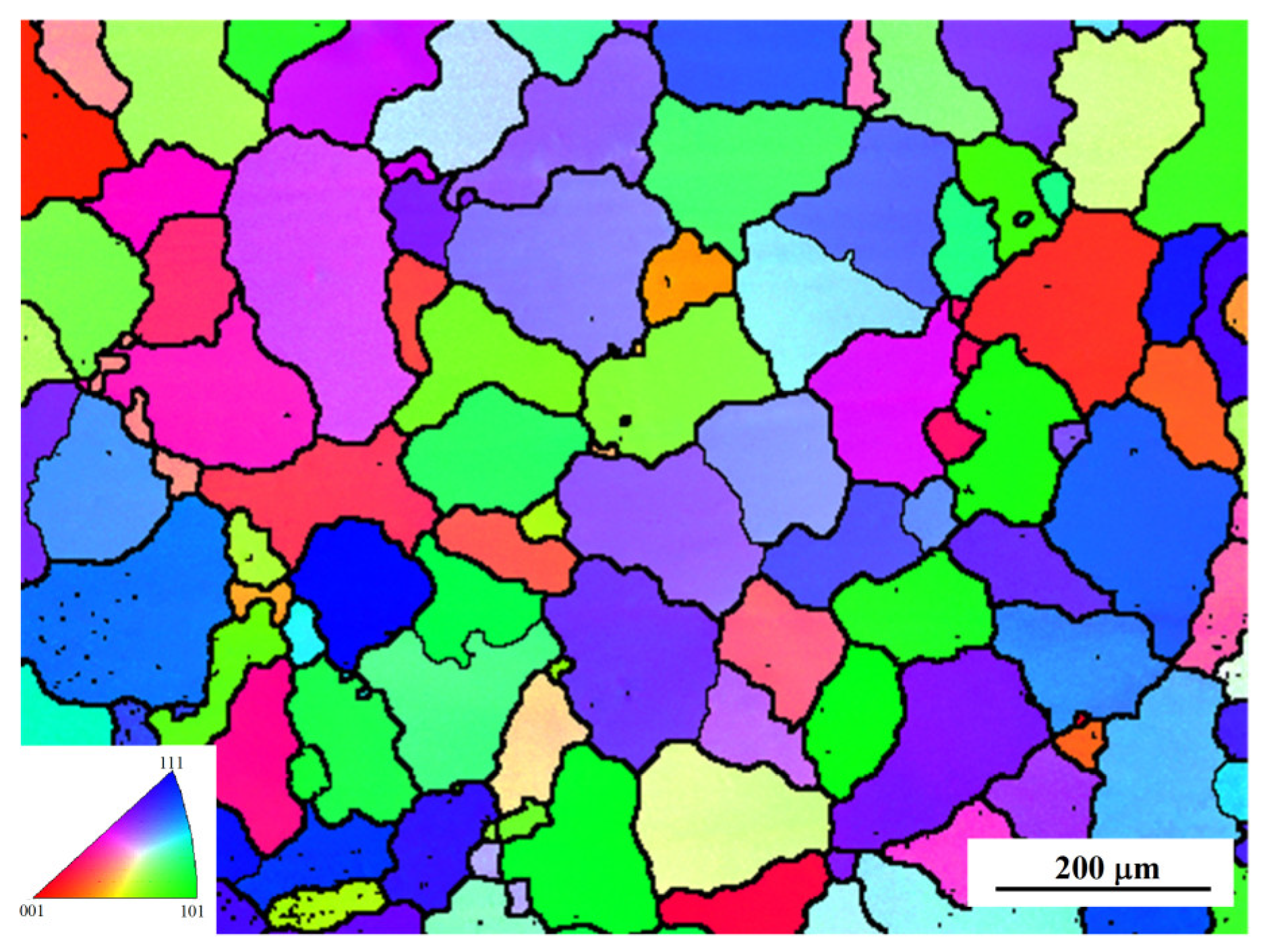
In this study, the experimental material was obtained from a homogenized 7075 aluminum alloy ingot produced by Innovation Industry & Trade Co., Binzhou City, Shandong Province, China. Its chemical composition is shown in Table 1. The cylindrical specimens with a diameter of 10 mm and a height of 15 mm, shown in Figure 1a, were machined along the axial direction of the ingot. After grinding and vibration polishing, the specimen was placed under SEM (accelerating voltage EHT = 20KV, aperture size 120 μm, and focal length = 15 mm) and the initial microstructure of the radial cross-section was observed, as shown in Figure 2, and the grains were equiaxed and uniform. The initial average grain size was approximately 107 μm, which was measured using the NanoMeasure 1.2 software.
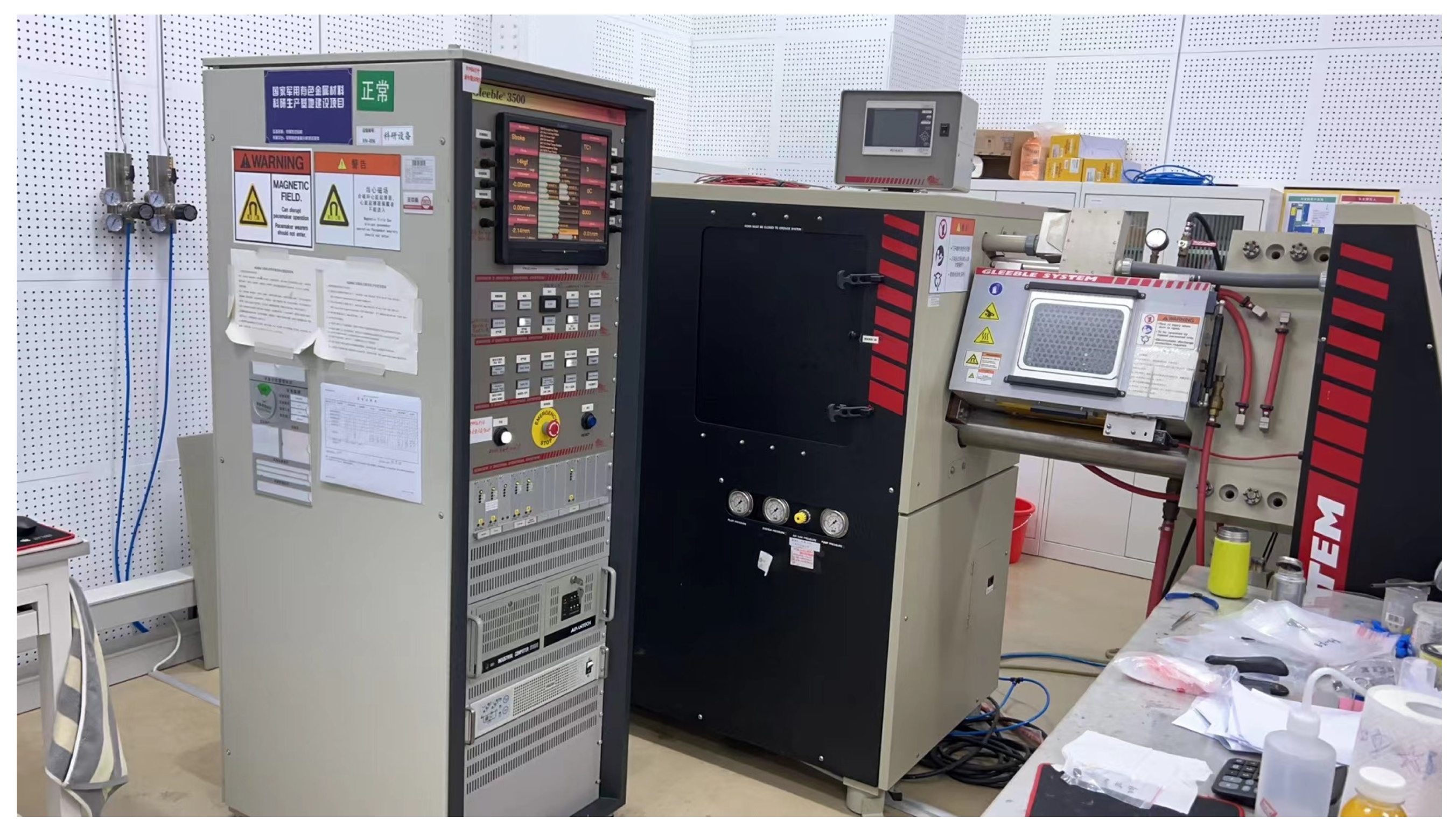
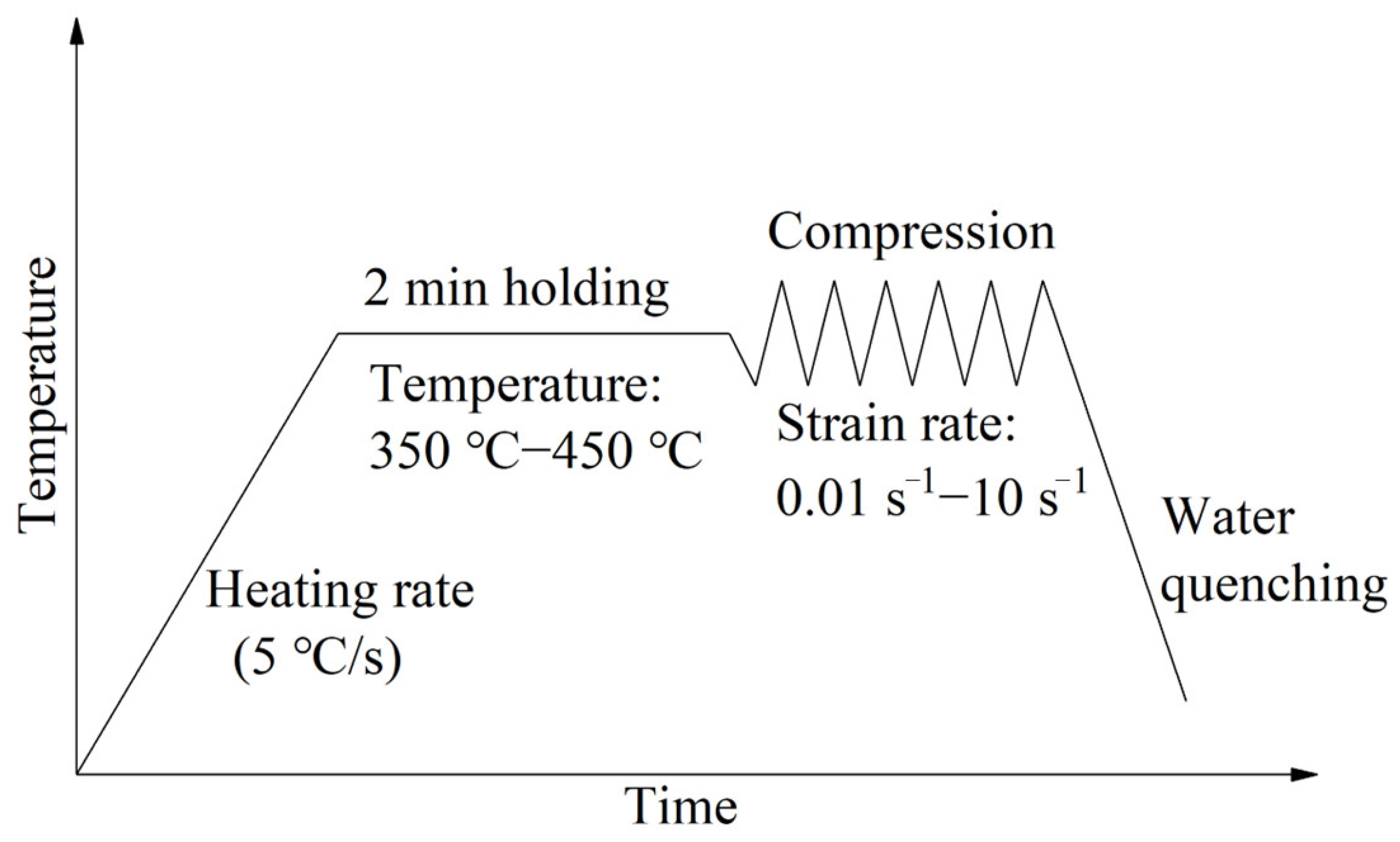
Hot compression tests were carried out on a thermal simulation testing machine named Gleeble-3500 (manufactured by DSI Corporation, St. Paul, MN, USA) at various deformation temperatures (300 °C, 350 °C, 400 °C, 450 °C) and strain rates (0.01 s−1, 0.1 s−1, 1 s−1, 10 s−1), and the compression height was 65%. The testing machine is shown in Figure 3. The temperature of the specimen throughout the process was monitored and the heating power was controlled by the temperature control system of the Gleeble-3500. Every specimen was heated to the set temperature by resistance heating at a rate of 5 °C/s and held for 2 min, as shown in Figure 4. Then, the compression process was conducted according to the set temperature and strain rate, after which the specimen was quenched in water immediately. The compressed specimen shape is shown in Figure 1b.

2.2. Flow Stress–Strain Curves and Their Corrections

Figure 5 shows the flow curves for 7075 aluminum alloy at different temperatures and strain rates. The storage or annihilation of dislocations [29] is involved throughout the deformation process, which leads to competition between the work-hardening and dynamic softening mechanisms. At the early stage of deformation, the reciprocity and multiplication of dislocations [30] lead to a rapid increase in flow stress, and the work-hardening mechanism dominates in this stage. As the strain increases, the rate of dislocation annihilation gradually approaches the rate of dislocation storage, and the work-hardening and the dynamic softening mechanisms reach equilibrium. Then, the flow stress slowly increases to the maximum value and stabilizes. At the later stage of deformation, the rate of dislocation annihilation exceeds the rate of dislocation storage and the dynamic softening mechanism slightly dominates, and thus the flow stress slowly decreases with the increase in strain. Under different tempertures and strain rates, as the deformation temperature decreases and the strain rate increases, the flow stress increases and the equilibrium point between the work-hardening and the dynamic softening mechanisms also shifts to the right, because lower temperatures bring slower thermal activation [29] and cause slower dislocation annihilation, and higher strain rates lead to a shorter deformation time and cause faster dislocation storage, and then both the strain at which the annihilation and storage of dislocations reach equilibrium and dislocation density increase.
In order to make the constitutive model obtained by the traditional linear fitting method more reliable, the original stress–strain curves were corrected to diminish the influence of plastic deformation heat and the friction factor on flow stress, according to Equations (1)–(3) [17,20]. The deformation heat correction was applied on the basis of the friction correction, and the corrected stress–strain curves at different temperatures and different strain rates are shown in Figure 5. The correction values of flow stress at high strain rates were significantly larger than those at low strain rates, where the correction value for the flow curve at 300 °C and 10 s−1 was as high as approximately 9%. This is because specimens compressed at high strain rates generate a large amount of heat internally, and the deformation time is not sufficient for the heat to apparently dissipate, and, accordingly, their deformation heat correction values are larger.

3. Identification of Modified Zerilli–Armstrong (M-ZA) Model Parameters by Inverse Analysis Method

3.1. Identification of M-ZA Model Parameters by Linear Fitting Method

In this study, the modified ZA model is used to describe the flow behavior of AA7075, as shown in Equation (4) below:
σ = C 1 + C 2 ε n exp C 3 + C 4 ε T + C 5 + C 6 T ln ε ˙
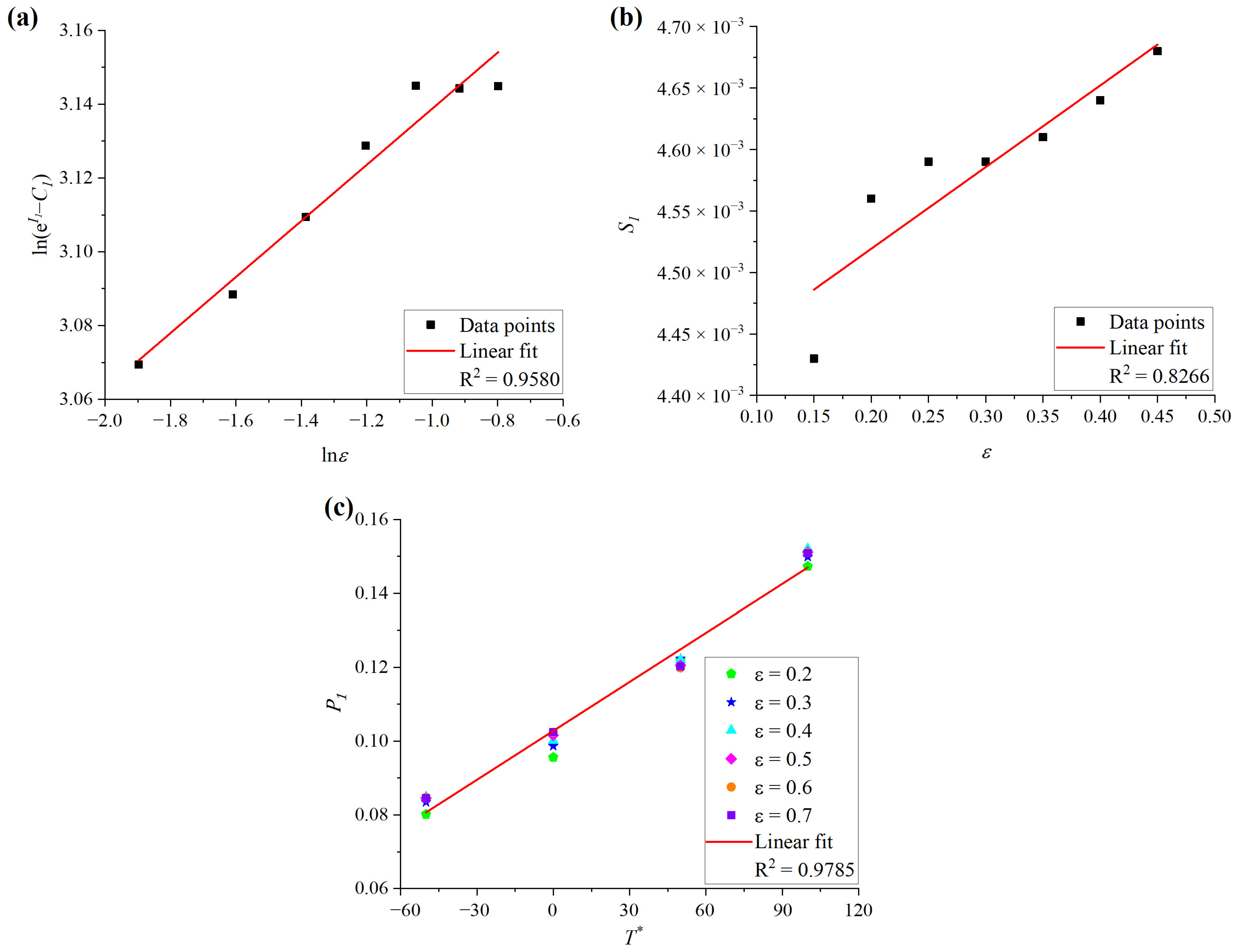
where σ is the flow stress (MPa), ε is the strain, ε ˙ = ε ˙ / ε ˙ ref , ε ˙ ref is the reference strain rate, and T = T T ref , T ref is the reference temperature. Here, 350 °C and 0.1 s−1 are chosen as the reference temperature and reference strain rate, respectively. C 1 ,   C 2 ,   C 3 ,   C 4 ,   C 5 ,   C 6 , and n are material constants, where the value of C 1 is the yield stress of the material at the reference temperature and reference strain rate, and C 1 = 77.30 MPa . The detailed procedures used to obtain other material parameters can be found in previous research [9,10,31]. Three intermediate variables named I 1 , S 1 , and P 1 were used, and the relationship equations between these variables and material parameters are shown in Equations (5)–(7), while the ln ε , ln e I 1 C 1 data points, ε , S 1 data points, and T , P 1 data points that were calculated, and their fitted lines, are shown in Figure 6a–c, respectively. Then, based on the corrected stress, the identified material parameters of the M-ZA model obtained via the linear fitting method are as shown in Table 2.
e I 1 = C 1 + C 2 ε n
S 1 = C 3 + C 4 ε
P 1 = C 5 + C 6 T

3.2. The Establishment of FEM Embedding M-ZA Model Based on Abaqus–Uhard Subroutine

In order to simulate hot compression tests using the M-ZA model, the M-ZA model was embedded into the Uhard subroutine, as shown in Equations (8)–(11), where SYIELD is the yield stress for isotropic plasticity; HARD (1), HARD (2), and HARD (3) are the variations of SYIELD with respect to the equivalent plastic strain, the equivalent plastic strain rate, and temperature, respectively.
S Y I E L D = σ ε , ε ˙ , T = C 1 + C 2 ε n exp C 3 + C 4 ε T + C 5 + C 6 T ln ε ˙
H A R D 1 = σ ε , ε ˙ , T / ε = C 2 n ε n 1 exp C 3 + C 4 ε T + C 5 + C 6 T ln ε ˙
C 4 C 1 + C 2 ε n T exp C 3 + C 4 ε T + C 5 + C 6 T ln ε ˙
H A R D 2 = σ ε , ε ˙ , T / ε ˙ = C 1 + C 2 ε n C 5 + C 6 T ) exp C 3 + C 4 ε T + C 5 + C 6 T ln ε ˙ / ε ˙
H A R D 3 = σ ε , ε ˙ , T / T = C 1 + C 2 ε n C 3 + C 4 ε + C 6 l n ε ˙ exp C 3 + C 4 ε T + C 5 + C 6 T l n ε ˙
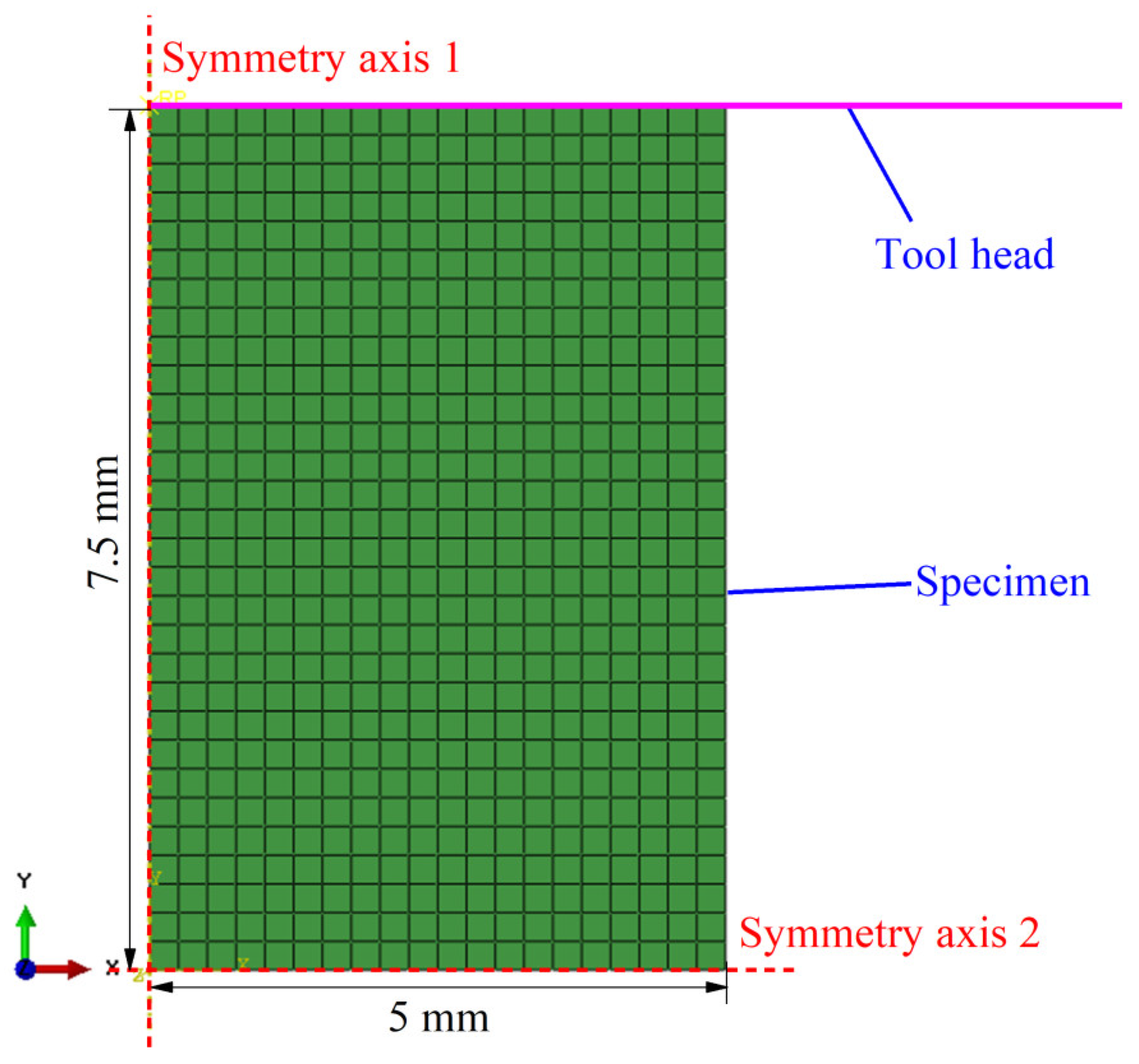
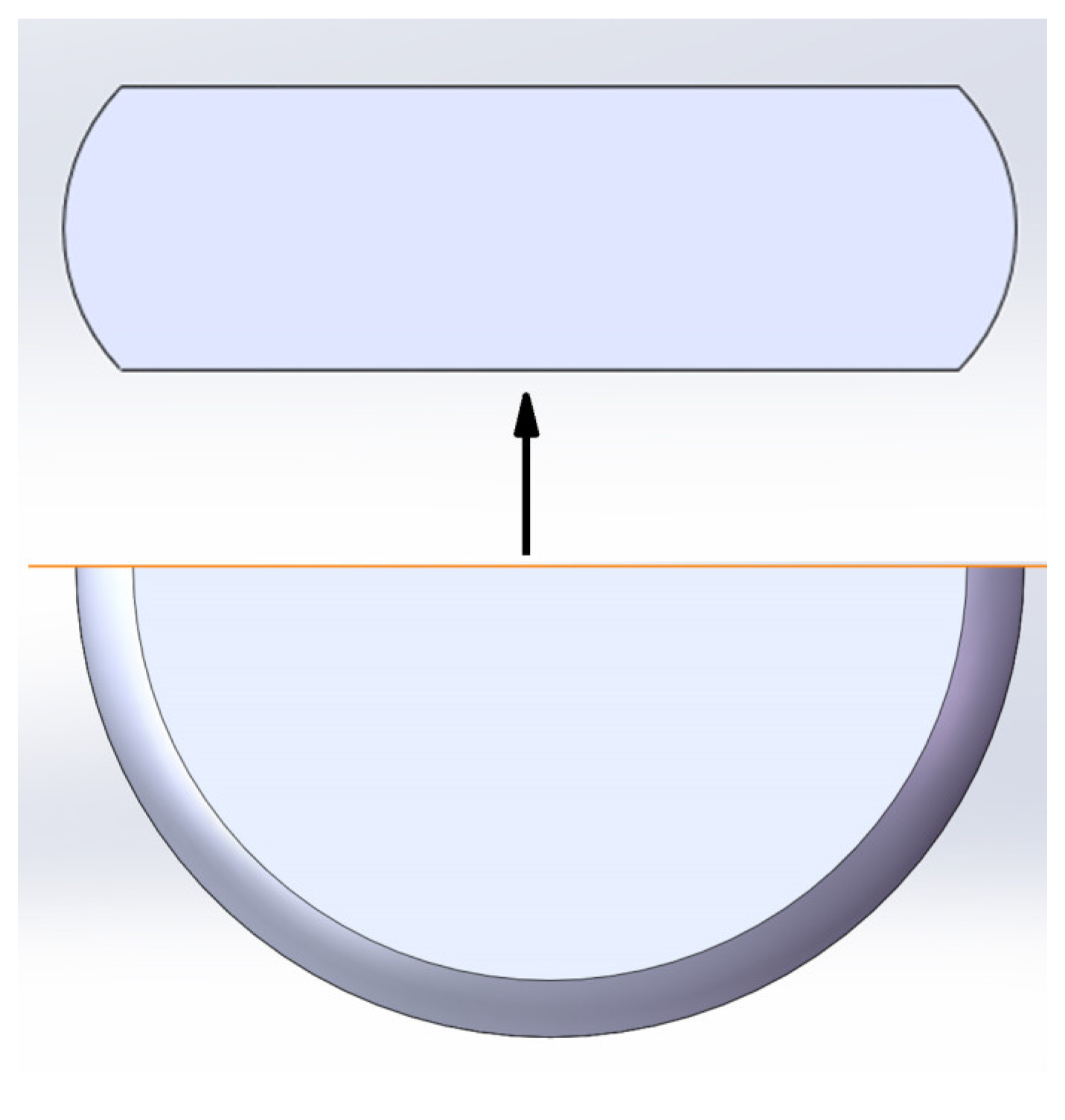
A two-dimensional axisymmetric thermo-mechanical FEM was built in the Abaqus CAE 6.14-1 software, as shown in Figure 7, and the axis of symmetry is marked as symmetry axis1 in Figure 7. The model contains two parts, the rigid tool head and the deformable specimen. The former is simplified as a straight line, which consists of two nodes that can be used to output force–displacement data. The specimen in FEM is symmetric about the x-axis, and the symmetry axis is marked as symmetry axis2 in Figure 7. One coupled temp–displacement (transient) step is created after the initial step and the number of increments is set to 100. After convergence tests on the element size, element shape, linear element, or second-order element and the number of increments, CAX8RT elements (an 8-node axisymmetric thermally coupled quadrilateral, biquadratic displacement, bilinear temperature, reduced integration) were used to simulate specimens. The number of elements was 601 and the number of nodes was 1902, the initial element size was 0.25 mm, and the meshing method was based on previous research [22,27]. The interactions specifying a penalty friction coefficient between the specimen and tool head were created, and the surface-to-surface contact type with finite sliding was selected. The thermo-physical parameters shown in Table 3 were inputted into the FEM.
The displacement boundaries of the tool head in the X direction and XY direction were set to 0 and the temperature boundary of the specimen was set to the temperature setting in the initial step. In order to simulate hot compression tests at a constant strain rate, the displacement boundary of the tool head in the Y direction was set to be user-defined in the coupled temp–displacement step, and the displacement function was defined in the DISP subroutine in the coupled temp–displacement step, as shown in Equation (12), where U 1 represents the displacement in the Y direction in this study. T I M E 2 represents the value of total time at the beginning of the current increment.
U 1 = 7.5 · exp ε ˙ · T I M E 2 7.5

3.3. Determination of the Friction Coefficient under Each Deformation Condition

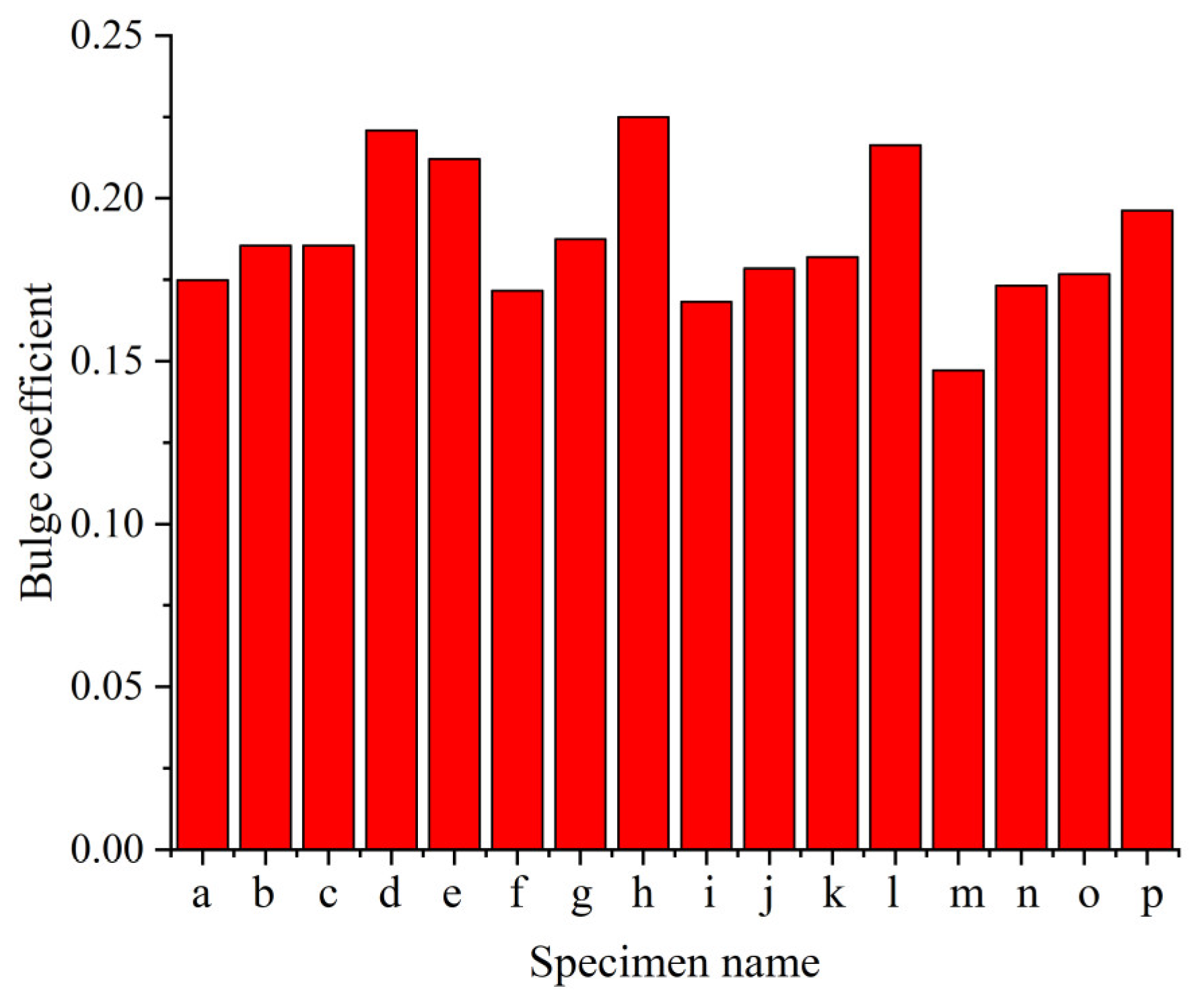
In order to determine the friction coefficients of 16 compression tests, the variable named the bulge coefficient [20] b and the equivalent radius R f were introduced, and the former represents the amount of bulge of the compressed specimens, as shown in Equations (13) and (14), where R M , R T , h , R 0 , and h 0 are the maximum radius, the top radius, the remaining height, the initial radius, and the initial height of the compressed specimens, respectively. After measuring the maximum radii, the top radii, and the heights of 16 compressed specimens under all deformation conditions, their bulge coefficients were calculated, as shown in Figure 8, where the specimens compressed at 300 °C and 0.01 s−1-10 s−1 are named “a” to “d”, the specimens compressed at 350 °C and 0.01 s−1-10 s−1 are named “e” to “h”, the specimens compressed at 400 °C and 0.01 s−1-10 s−1 are named “i” to “l”, and the specimens compressed at 450 °C and 0.01 s−1-10 s−1 are named “m” to “p”.
b = 4 R M R T R f · h h 0 h
R f = R 0 h 0 / h
E r r b = abs b e x p b s i m / b e x p
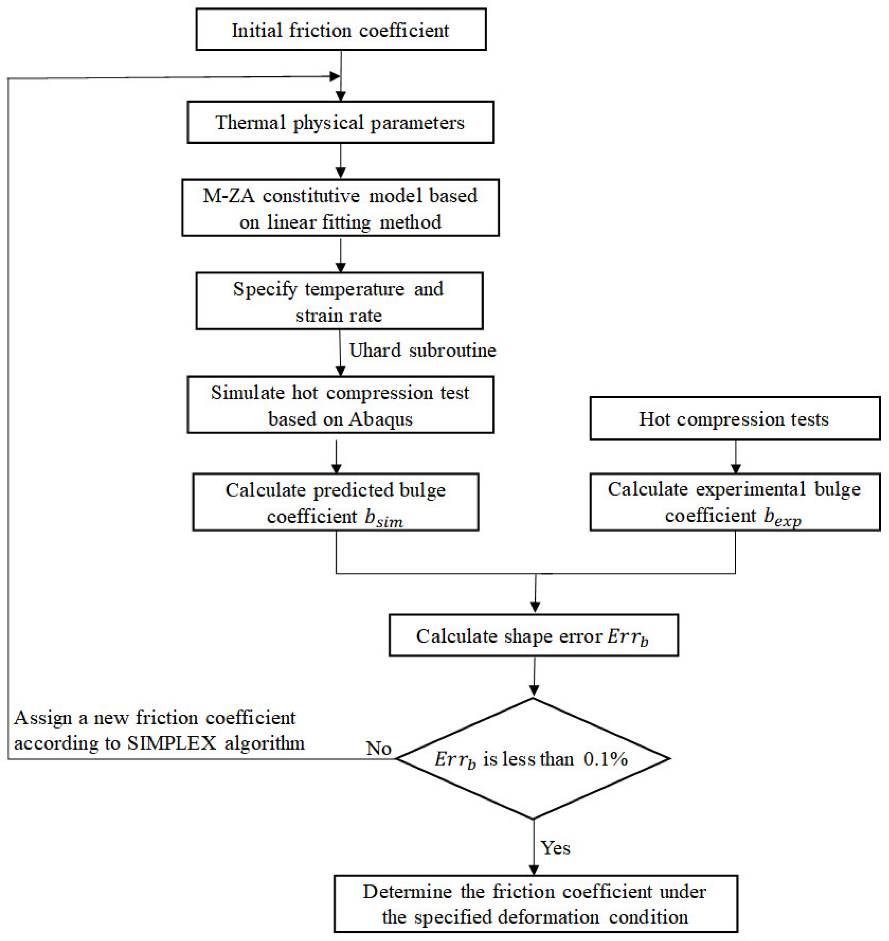
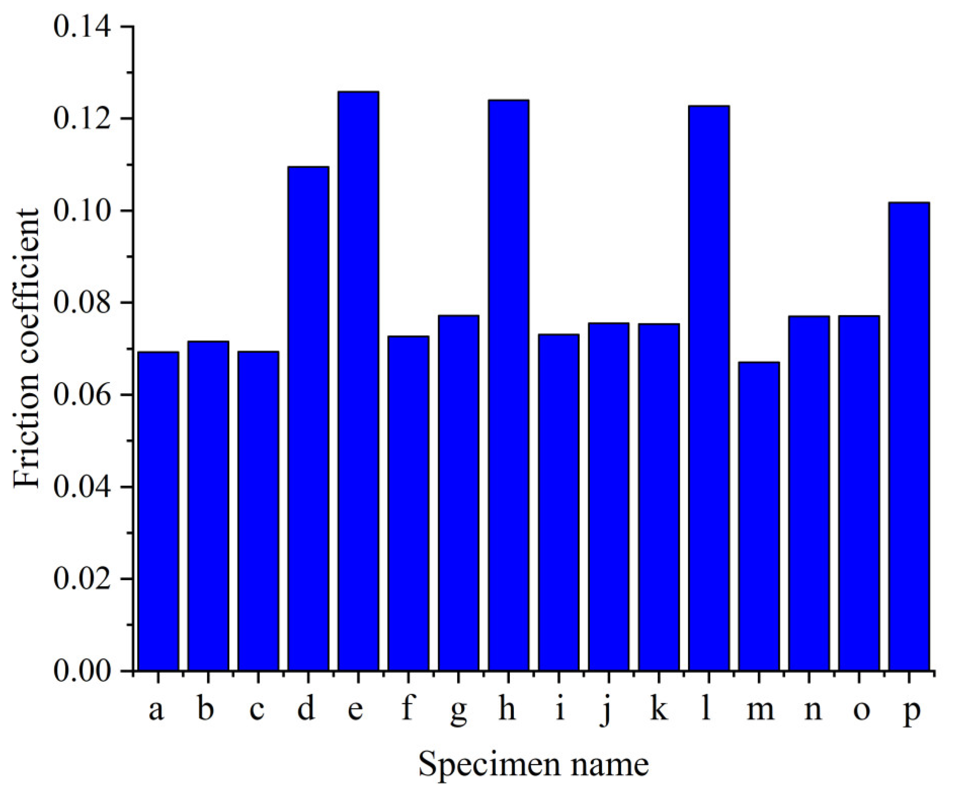
As shown in Figure 9, the initial friction coefficient, the thermo-physical parameters of the material, and the M-ZA model based on the linear fitting method were inputted into the FE model built in Section 3.2 and the predicted bulge coefficient b s i m was solved. Comparing the predicted bulge coefficient b s i m with the experimental bulge efficient b e x p , the shape error E r r b was calculated, as shown in Equation (15). With the minimization of the shape error as the optimization objective, the SIMPLEX algorithm was adopted to assign a new friction coefficient and hot compression simulation process under the specified deformation conditions; this was repeated until the shape error E r r b was less than 0.1%, and finally the optimized friction coefficient was obtained. By inputting different temperatures and strain rates in the FE model, the friction coefficient under each deformation condition could be determined separately by the inverse analysis method, as shown in Figure 10, where the maximal friction coefficient is 0.1258 and the minimum friction coefficient is 0.06706, and they differ by 46.69%. The friction coefficients between specimens named “d”, “e”, “h”, “l”, and “p” and the tool head were significantly higher than those of other specimens. The predicted friction coefficient between “e” (350 °C-0.01 s−1) and the tool head was 0.1258. The predicted friction coefficient between “j” (400 °C-0.1 s−1) and the tool head was 0.07553. The comparisons of the experimental and the predicted shapes of “e” and “j” are shown in Figure 11, respectively, and the experimental shapes are axial sections obtained by wire cutting along the center line of the compressed specimen, as shown in Figure 12. It can be observed that the amount of bulge of the experimental specimens is in good agreement with the shape of the simulated specimens, and the prediction errors of the maximum radii and the top radii are less than 1%, which further proves the reliability of determining the friction coefficient under different deformation conditions by the inverse analysis method based on the shape error E r r b .

3.4. Identification of M-ZA Model Parameters by Inverse Analysis Method

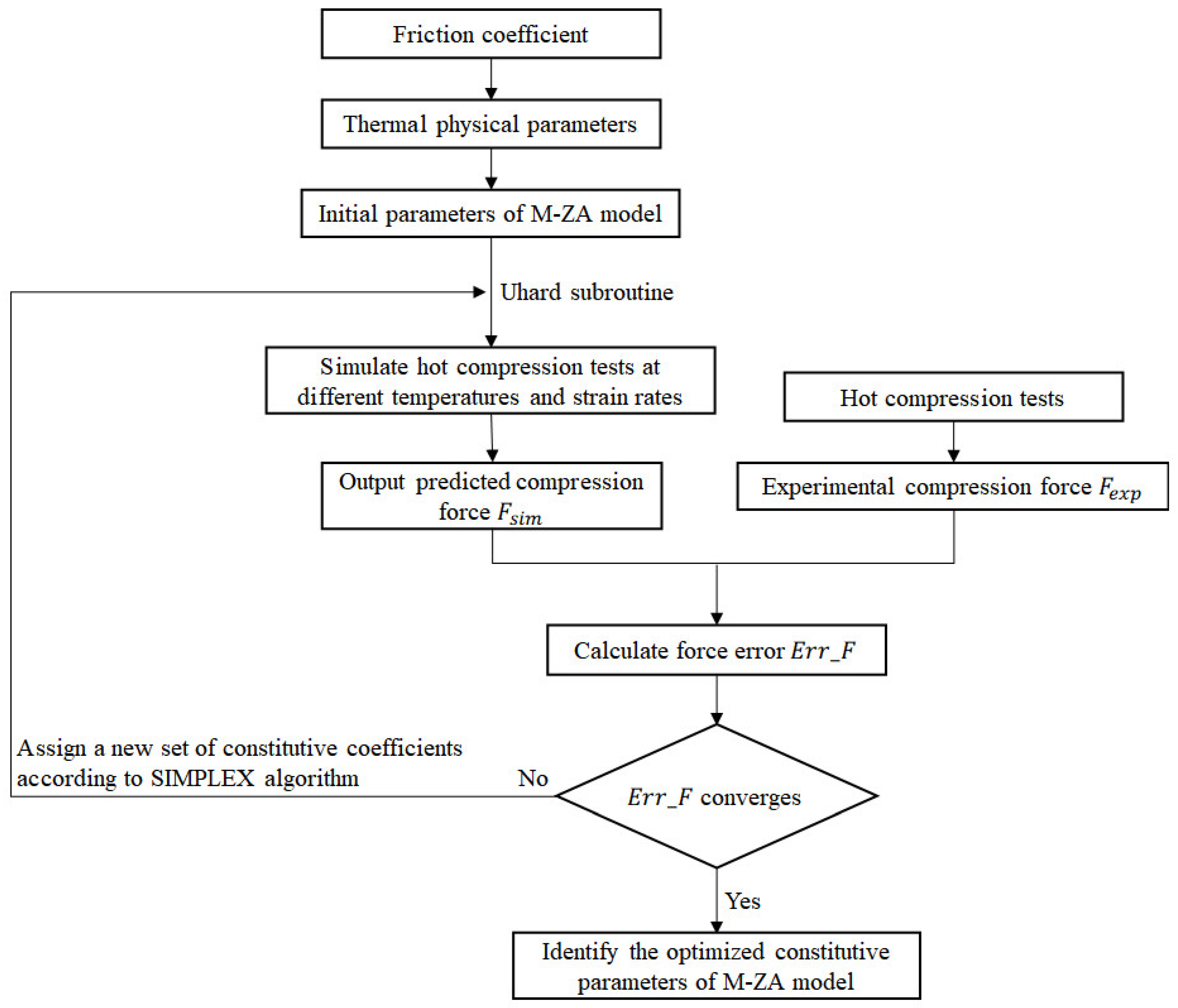
The upper and lower boundaries of the nine material parameters of the M-ZA model are specified in Table 4, and the detailed process of the inverse analysis method is shown in Figure 13. Firstly, the friction coefficients obtained in Section 3.3, and the thermo-physical parameters of AA7075, were input into the FEM, and then 10 sets of initial material parameters were specified in the mode-FRONTIER 2020R3 software using the Uniform Latin Hypercube algorithm, followed by hot compression simulation processes at different temperatures and strain rates based on the Abaqus software, which outputted compression force–displacement data. As shown in Equation (16), the force error E r r _ F between predicted force F s i m and experimental force F e x p was calculated. From the 10th loop onward, taking the minimization of the force error as the optimization objective, the SIMPLEX algorithm was adopted to assign a new set of constitutive parameters, and the hot compression simulation processes were repeated under different temperatures and strain rates until the force error E r r _ F converged ( E r r _ F of the i th iteration step and E r r _ F of the i + 1 th iteration step differed by less than 0.001%), and the final set of constitutive parameters were the optimized M-ZA model parameters based on the inverse analysis method.
E r r _ F = i = 1 N F e x p F s i m 2 i = 1 N F e x p 2
A A R E = 1 N i = 1 N F e x p F s i m F e x p
where N = 160, and these experimental data points are obtained from 16 compression force–displacement curves, and every 10 data points are taken from each curve (stroke s 1.5 ,   2 ,   2.5 ,   3 ,   3.5 ,   4 ,   4.5 ,   5 ,   5.5 ,   6 ).
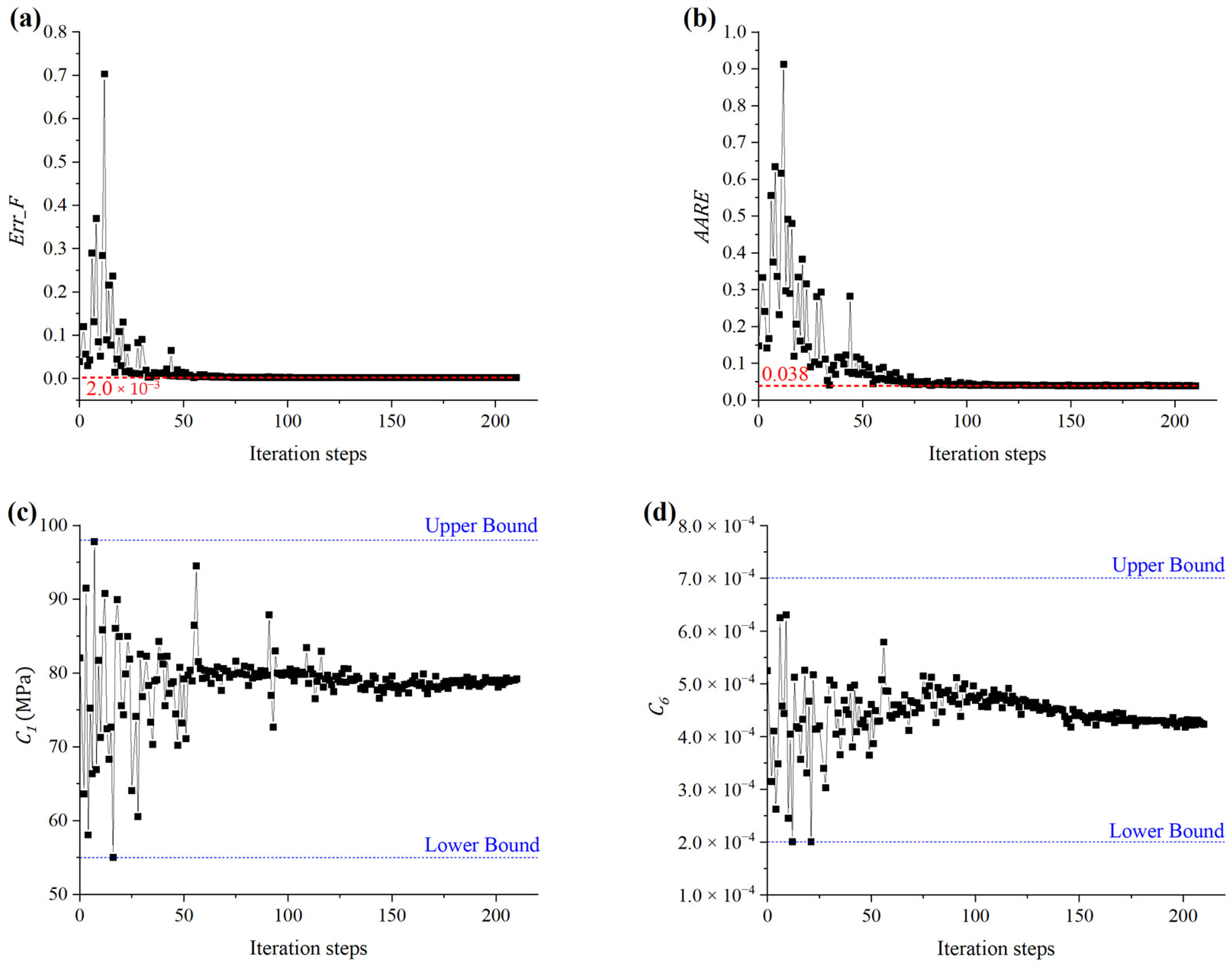
Table 5 shows the optimized M-ZA model parameters obtained after 210 iterations based on the inverse analysis method. As shown in Figure 14a,b, the amplitude of the fluctuation of E r r _ F gradually decreases from the 1st to the 50th iteration step, and after 50 iteration steps, E r r _ F obviously converges to a stable value of 2 × 10⁻³, and A A R E obviously converges to a stable value of 3.8% after 100 iteration steps, which is calculated according to Equation (17). Figure 14c,d show that the material parameters C 1 and C 6 converge to stable values after 150 iteration steps, and this demonstrates the reasonableness of the upper and lower boundaries of the material parameters.
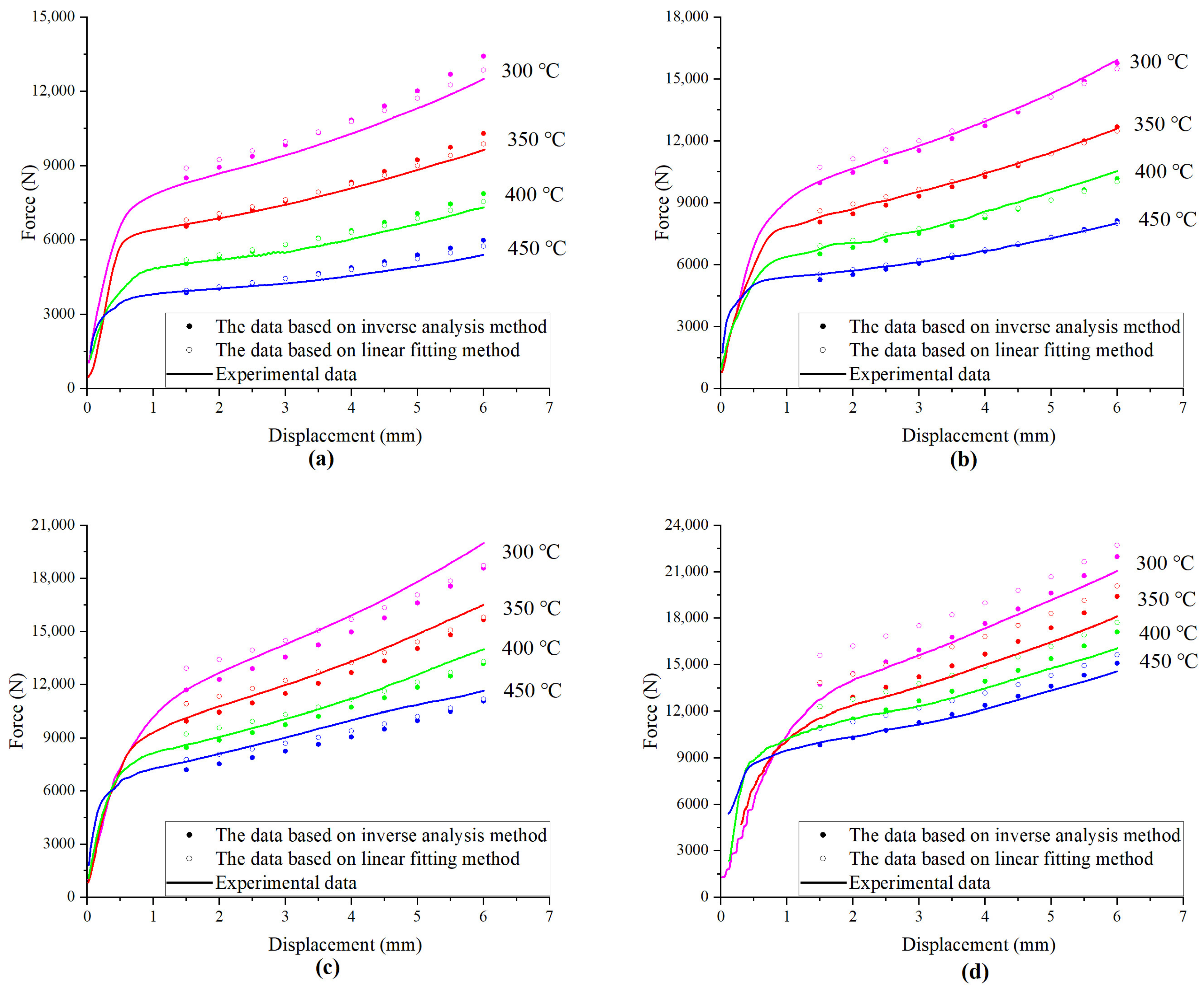
Figure 15 shows the experimental force–displacement curves and the simulated force–displacement data under different temperatures and strain rates, which were output by the FE model embedding the M-ZA constitutive model determined by the inverse analysis method and linear fitting method, respectively. The results show that the prediction accuracy of the M-ZA models based on the inverse analysis technique and linear fitting method is high at strain rates of 0.01 s−1, 0.1 s−1 and 1 s−1. However, when the strain rate is 10 s−1, as shown in Figure 15d, the M-ZA model based on inverse analysis predicts the compression force more accurately than the traditional linear fitting method, and the average prediction errors are 3.3% and 11.0%, respectively. The simulated compression force obtained by the linear fitting method is apparently larger than the experimental force under the highest strain rate, which is caused by the excessive deformation heat correction to the stress–strain curves in Section 2.2, or the limitations of the traditional linear fitting method.

4. Application of the M-ZA Model Determined by Inverse Analysis Method in the Near-Net Forging of Aluminum Alloy Wheels

The M-ZA model determined by the inverse analysis method was applied to build the initial and final FE models simulating the near-net forging of 16-inch aluminum alloy wheels in the Deform-3D 6.14 software. In addition, the initial and the final closed-die forging experiments were conducted.

4.1. Finite Element Simulation of Near-Net Forging of Wheels

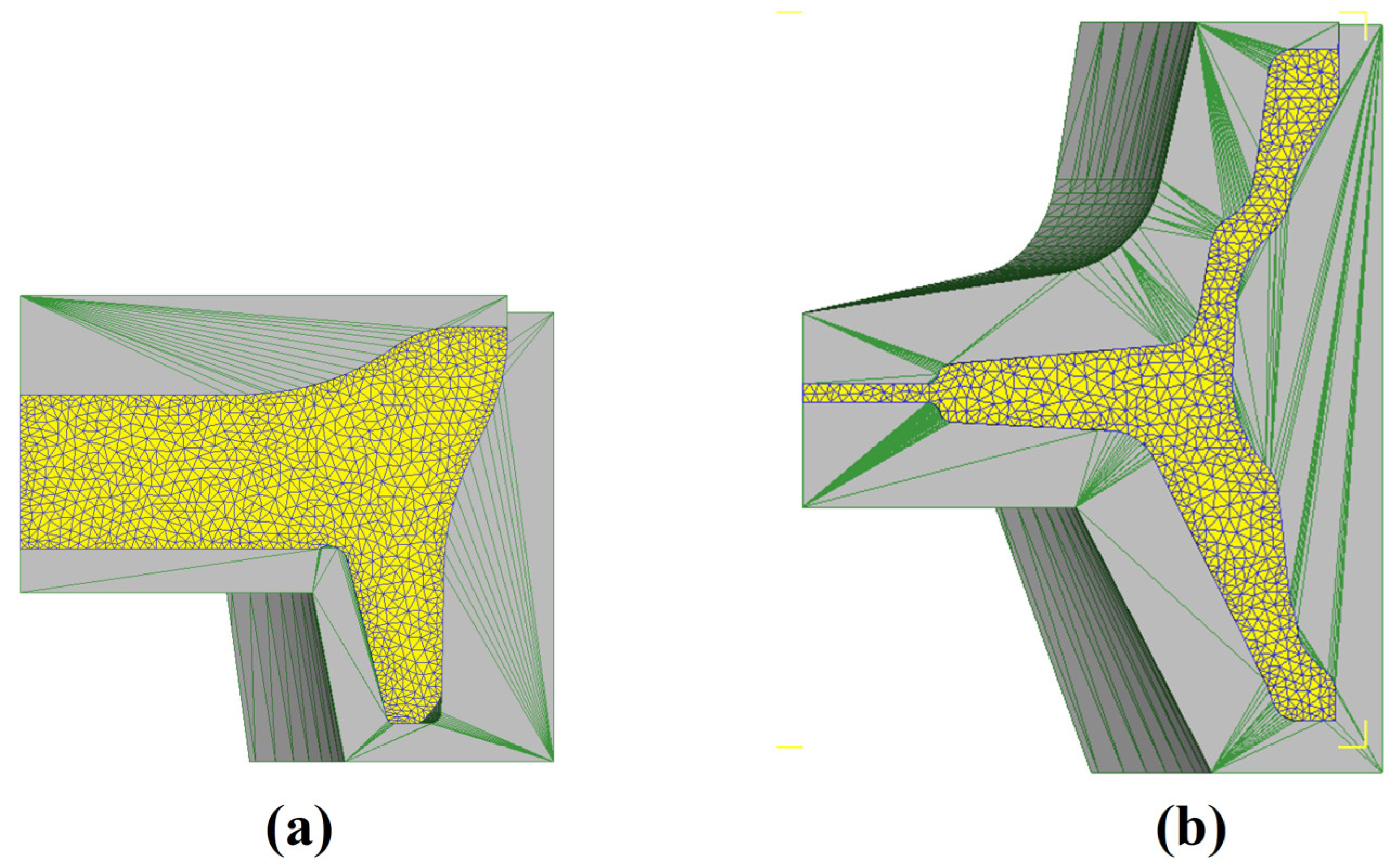
The billet size, initial temperature of the dies and billet, forging speed, and the transfer time of the preform are shown in Table 6. The initial forgings and final forgings are axisymmetric, so one eighth of the forgings and dies are used to build the FE models considering the calculation cost. The sides of all the dies and forgings are set as symmetric surfaces. Figure 16a shows the initial forging FE model of 7075 aluminum alloy wheels, and the cylindrical billet is forged into the preform in order to increase the plastic deformation. Figure 16b shows the final forging FE model, and the disc and the rim are formed during the final forging process. The M-ZA model is embedded in the Deform-3D software based on the user subroutine.

4.2. Experiments on Near-Net Shape Forging of Wheels

According to the parameters in Table 6, the near-net forging experiments of 7075 aluminum alloy wheels were carried out after developing a new set of dies. H13 steel dies and billets were heated for 3 h under their set temperatures. The heated billet was placed by the manipulator into the cavity with a lubricant under a 5000-ton hydraulic press (manufactured by Dayi Forging Equipment Co., Xuzhou City, Jiangsu Province, China) for the initial forging process, and then the preform was taken out by the manipulator, transferred to the next manipulator, and placed into the cavity with a lubricant under a 10,000-ton (manufactured by Dayi Forging Equipment Co., Xuzhou City, Jiangsu Province, China) hydraulic press for the final forging process, enclosed by one bottom die and four closed lateral dies. As shown in Figure 17a, the final forging process was finished, and four lateral dies were drawn back and thus the forged wheel could be taken out. Figure 17b shows that the final forging was filled well and had a thin flash. After machining, heat treatment, and quality inspection, the finished wheel could be obtained.

4.3. Comparisons of Experimental and Predicted Forging Load–Stroke Curves

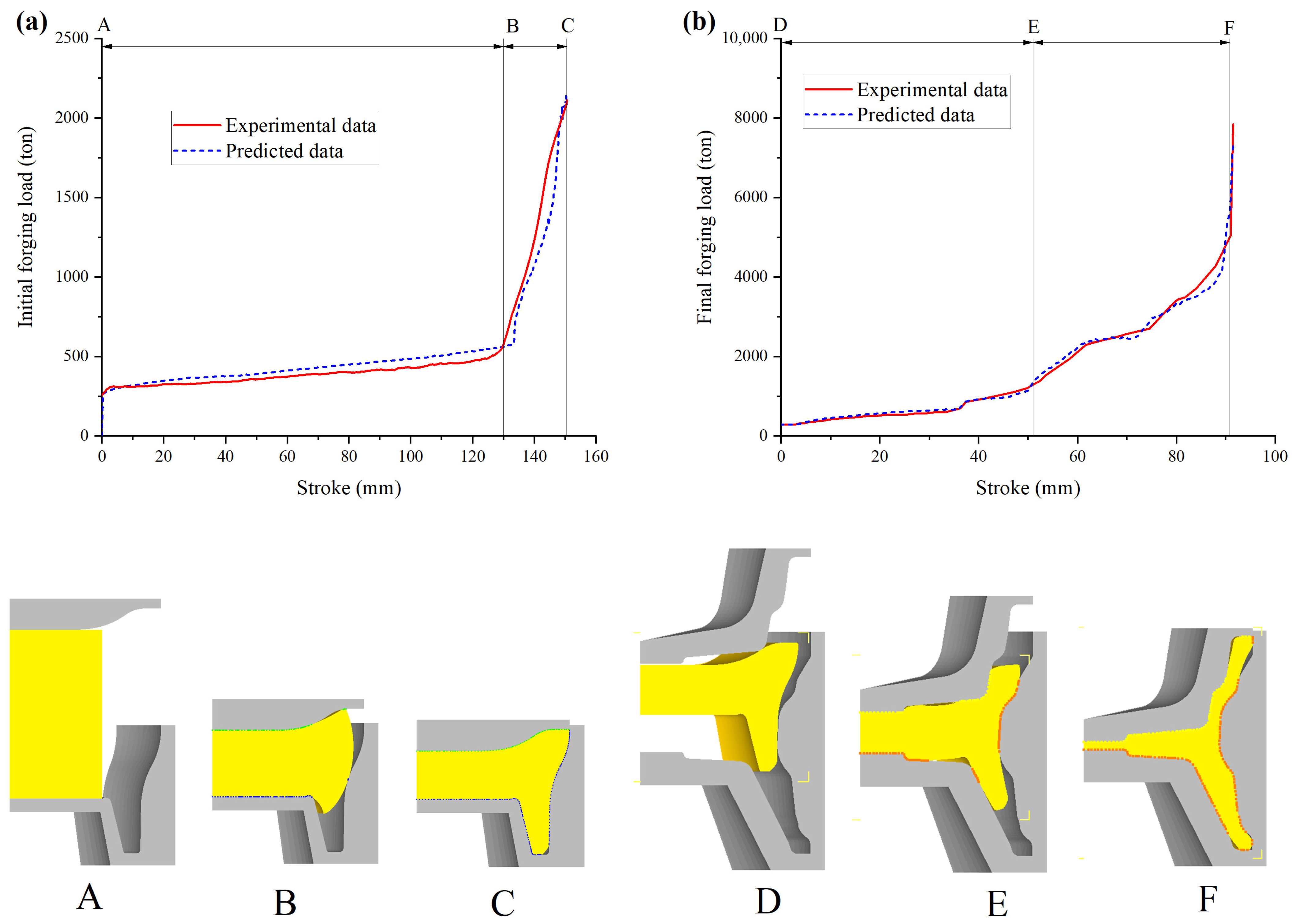
Figure 18 shows the experimental load–stroke data read from the hydraulic press and the predicted load–stroke curves obtained from the above FE models. As shown in Figure 18a, in the initial forging process, the predicted forging load–stroke curve is in good agreement with the experimental one. In the AB stage of the curves, the billet is upset so the load increases slowly. At point “B”, the billet comes into contact with the side wall of the female die and extrusion starts, and thus the load increases rapidly in the BC stage. The initial forging is not suitable to fill the specimen completely if the upper flash affects the die filling of the final forging process. The average error between the experimental and predicted load–stroke curves is 10.0% in the AB stage and 12.9% in the BC stage, and the experimental and predicted maximum forming load during the initial forging process are 2111 tons and 2118 tons, respectively, and they differ by 1.00%.
Figure 18b shows that the predicted forging load–stroke curve is in good agreement with the experimental one in the final forging process. The load increases slowly in the DE stage, which is because the contact area between the preform and dies is still relatively small in the early stage of final forging. In the EF stage, the disc is filled completely, and forward and backward extrusions exist; the thickness of the formed rim decreases, and thus the forging load increases more quickly. At point “F”, the material touches the top and bottom of the die cavity. Then, as the stroke continues to increase, the die cavity is filled completely, and the load increases steeply. The average error between the experimental and predicted load–stroke curves is 7.15% in the DE stage and 4.60% in the EF stage, and the predicted and experimental maximum forming loads during the final forging are 7319 tons and 7841 tons, respectively, and they differ by 6.66%. These above load average errors were calculated according to Equation (18), where j is the number of selected load–stroke data points, L e x p is the measured forging load, and L s i m is the predicted forging load. In this study, the data points were selected in equal stroke intervals of 0.5 mm.
E r r a v g = 1 j i = 1 j L e x p L s i m L e x p × 100 %
By comparing the above experimental load–stroke curves with the predicted data from the forging FE simulation, it is verified that the M-ZA model obtained by the inverse analysis method is reliable and can provide a theoretical guideline for the near-net shape forging process of aluminum alloy wheels.

5. Conclusions

In order to accurately determine the material parameters of the physical-based constitutive model (M-ZA model) of Al-Zn-Mg alloy (7075), the two-times inverse analysis method was applied to identify nine material parameters in this study, and the main conclusions are as follows.
  • Based on the bulge coefficients of the compressed specimens, 16 friction coefficients between the compressed specimens and tool head at different temperatures and strain rates were determined by the inverse analysis method, where the maximal friction coefficient was 0.1258 and the minimum friction coefficient was 0.06706, and they differed by 46.69%.
  • Based on the force–displacement data of the compressed specimens and the above 16 determined friction coefficients, nine material parameters of the M-ZA model were identified by the second inverse analysis technique, and the global average error between the experimental and predicted force–displacement curves was 3.8%. Moreover, the prediction accuracy of the compression force of the M-ZA model based on the inverse analysis method was higher apparently than that of the M-ZA model based on the traditional linear fitting method when the strain rate was 10 s−1, and the average prediction errors were 3.3% and 11.0%, respectively.
  • The forging FE models of 7075 aluminum alloy wheels were built based on the Deform-3D platform, and the near-net shape forging processes of the wheels were simulated. The near-net shape forging experiments of aluminum alloy wheels were carried out. The experimental forgings were filled well and the flashes were thin. The predicted forging load–stroke curves were in good agreement with the experimental data in all stages of the initial and final forging processes, and the load average error in each stage during the final forging process was less than 10%. This not only verifies the reliability of the M-ZA model obtained by using the two-times inverse analysis method, but also provides theoretical guidance for the formulation and optimization of the near-net-shape forging process parameters of aluminum alloy wheels.

Author Contributions

Conceptualization, L.C. and W.J.; methodology, L.C., C.Y. and R.W.; software, L.C.; validation, L.C.; formal analysis, L.C., H.J. and X.Z.; investigation, L.C.; resources, C.Y.; data curation, L.C.; writing-original draft preparation, L.C.; writing-review and editing, L.C., C.Y., R.W., W.J., H.J. and X.Z.; visualization, L.C.; supervision, C.Y., R.W. and W.J.; project administration C.Y. and R.W. All authors have read and agreed to the published version of the manuscript.

Funding

This research received no external funding.

Institutional Review Board Statement

Not applicable.

Informed Consent Statement

Not applicable.

Data Availability Statement

The data presented in this study are available on request from the corresponding author. The data are not publicly available due to involving business information.

Conflicts of Interest

The authors declare no conflict of interest.

References

  1. Kim, Y.H.; Ryou, T.K.; Choi, H.J.; Hwang, B.B. An Analysis of the Forging Processes for 6061 Aluminum-Alloy Wheels. J. Mater. Process. Technol. 2002, 123, 270–276. [Google Scholar] [CrossRef]
  2. Li, L.; Wang, F. Simulation Study on Influence of Forming Process Parameters on Backward Extrusion Height of 6061 Aluminum-Alloy Wheel. In Applied Mechanics and Materials; Trans Tech Publications Ltd.: Zurich, Switzerland, 2012; pp. 363–366. [Google Scholar]
  3. Yang, T.S.; Luo, K.C. Friction Factor of 6061 Aluminum Alloy and Application to The Finite Element Analysis of Wheel Forging. Key Eng. Mater. 2017, 739, 231–234. [Google Scholar] [CrossRef]
  4. Ma, Z. Study on Closed-Die Forging Technology of Forging Aluminum Alloy Wheel. Forg. Stamp. Technol. 2015, 40, 1–4. [Google Scholar]
  5. Zhang, L.P.; Qi, B.N.; Zhao, D.J. One-Piece Forged Aluminum Alloy Wheel Process Steps Analysis and Dies Design. In Proceedings of the International Conference on Mechanical Engineering and Mechanics, Wuxi, China, 5–7 November 2007; Volume 1–2, pp. 1641–1646. [Google Scholar]
  6. Chen, S.Y.; Shu, X.D.; Lu, Y.J. Effect of 6061 Aluminum Alloy Wheel Forging and Spinning Process Parameters on Forming Quality. Metalurgija 2022, 61, 317–320. [Google Scholar]
  7. Lu, Y.J.; Shu, X.D. Effect of Aluminum Alloy Wheel Forging and Spinning Process Parameters on Forming Force. Metalurgija 2021, 60, 227–229. [Google Scholar]
  8. Samantaray, D.; Mandal, S.; Borah, U.; Bhaduri, A.K.; Sivaprasad, P.V. A Thermo-Viscoplastic Constitutive Model to Predict Elevated-Temperature Flow Behaviour in A Titanium-Modified Austenitic Stainless Steel. Mater. Sci. Eng. A 2009, 526, 1–6. [Google Scholar] [CrossRef]
  9. Yu, R.; Wang, P.; Li, G.; Fang, M.; Xu, G.; Zhang, M. Correction and Modeling of Flow Stress During Hot Deformation of 7055 Aluminum Alloy. J. Mater. Eng. Perform. 2022, 31, 6870–6879. [Google Scholar] [CrossRef]
  10. Rudra, A.; Ashiq, M.; Das, S.; Dasgupta, R. Constitutive Modeling for Predicting High-Temperature Flow Behavior in Aluminum 5083+10wtpct Sicp Composite. Metall. Mater. Trans. B Process Metall. Mater. Process. Sci. 2019, 50, 1060–1076. [Google Scholar] [CrossRef]
  11. Wang, G.; Ma, G.; Wu, J. Research on Constitutive Model of 2099-T83 Aluminum-Lithium Alloy. J. Plast. Eng. 2019, 26, 174–181. [Google Scholar]
  12. Paturi, U.M.R.; Narala, S.K.R.; Pundir, R.S. Constitutive Flow Stress Formulation, Model Validation and Fe Cutting Simulation for Aa7075-T6 Aluminum Alloy. Mater. Sci. Eng. A Struct. Mater. Prop. Microstruct. Process. 2014, 605, 176–185. [Google Scholar] [CrossRef]
  13. Ashtiani, H.R.R.; Shayanpoor, A.A. Prediction of The Hot Flow Behavior of Aa1070 Aluminum Using the Phenomenological and Physically-Based Models. Phys. Met. Met. 2021, 122, 1436–1445. [Google Scholar] [CrossRef]
  14. Venugopal, S.; Srinivasan, G.; Venkadesan, S.; Seetharaman, V. A Note on The Determination of the Friction Factor by Means of the Reduction-Capacity Test. J. Mech. Work. Technol. 1989, 19, 261–266. [Google Scholar] [CrossRef]
  15. Shen, G.; Vedhanayagam, A.; Kropp, E.; Altan, T. A Method for Evaluating Friction Using A Backward Extrusion-Type Forging. J. Mater. Process. Technol. 1992, 33, 109–123. [Google Scholar] [CrossRef]
  16. Dadras, P. A Semi-Empirical Solution to Upset Forging. J. Eng. Ind. Trans. Asme 1981, 103, 478–483. [Google Scholar] [CrossRef]
  17. Ebrahimi, R.; Najafizadeh, A. A New Method for Evaluation of Friction in Bulk Metal Forming. J. Mater. Process. Technol. 2004, 152, 136–143. [Google Scholar] [CrossRef]
  18. Goetz, R.L.; Semiatin, S.L. The Adiabatic Correction Factor for Deformation Heating During the Uniaxial Compression Test. J. Mater. Eng. Perform. 2001, 10, 710–717. [Google Scholar] [CrossRef]
  19. Mostafaei, M.A.; Kazeminezhad, M. Hot Deformation Behavior of Hot Extruded Al–6mg Alloy. Mater. Sci. Eng. A 2012, 535, 216–221. [Google Scholar] [CrossRef]
  20. Peng, N.; Tang, G.; Liu, Z. Correcting Method of Flow Stress Curve for Hot Compression. Hot Work. Technol. 2012, 41, 12–15. [Google Scholar]
  21. Slooff, F.A.; Zhou, J.; Duszczyk, J.; Katgerman, L. Constitutive Analysis of Wrought Magnesium Alloy Mg–Al4–Zn1. Scr. Mater. 2007, 57, 759–762. [Google Scholar] [CrossRef]
  22. Zhang, C.; Ding, J.; Dong, Y.; Zhao, G.; Gao, A.; Wang, L. Identification of Friction Coefficients and Strain-Compensated Arrhenius-Type Constitutive Model by A Two-Stage Inverse Analysis Technique. Int. J. Mech. Sci. 2015, 98, 195–204. [Google Scholar] [CrossRef]
  23. Plumeri, J.E.; Madej, Ł.; Misiolek, W.Z. Constitutive Modeling and Inverse Analysis of the Flow Stress Evolution During High Temperature Compression of a New Ze20 Magnesium Alloy for Extrusion Applications. Mater. Sci. Eng. A 2019, 740–741, 174–181. [Google Scholar] [CrossRef]
  24. Gawad, J.; Kuziak, R.; Madej, L.; Szeliga, D.; Pietrzyk, M. Identification of Rheological Parameters on The Basis of Various Types of Compression and Tension Tests. Steel Res. Int. 2005, 76, 131–137. [Google Scholar] [CrossRef]
  25. Yanagida, A.; Liu, J.; Yanagimoto, J. Flow Curve Determination for Metal Under Dynamic Recrystallization Using Inverse Analysis. Mater. Trans. 2003, 44, 2303–2310. [Google Scholar] [CrossRef] [Green Version]
  26. Ding, S.; Khan, S.A.; Yanagimoto, J. Flow Behavior and Dynamic Recrystallization Mechanism of A5083 Aluminum Alloys with Different Initial Microstructures During Hot Compression. Mater. Sci. Eng. A 2020, 787, 139522. [Google Scholar] [CrossRef]
  27. Xu, L.; Yao, Z.; Liu, J.; Xue, Z.; Xu, C.; He, H.; Li, L. Constitutive Model Parameter Identification for 6063 Aluminum Alloy Using Inverse Analysis Method for Extrusion Applications. J. Mater. Eng. Perform. 2021, 30, 7449–7460. [Google Scholar] [CrossRef]
  28. Mulyadi, M.; Rist, M.A.; Edwards, L.; Brooks, J.W. Parameter Optimisation in Constitutive Equations for Hot Forging. J. Mater. Process. Technol. 2006, 177, 311–314. [Google Scholar] [CrossRef]
  29. Guo, Y.; Zhang, J.H.; Zhao, H.W. Microstructure Evolution and Mechanical Responses of Al-Zn-Mg-Cu Alloys During Hot Deformation Process. J. Mater. Sci. 2021, 56, 13429–13478. [Google Scholar] [CrossRef]
  30. Salvado, F.C.; Teixeira-Dias, F.; Walley, S.M.; Lea, L.J.; Cardoso, J.B. A Review on The Strain Rate Dependency of the Dynamic Viscoplastic Response of Fcc Metals. Prog. Mater. Sci. 2017, 88, 186–231. [Google Scholar] [CrossRef] [Green Version]
  31. Ma, Z.; Ji, H.C.; Pei, W.C.; Wang, S.F.; Li, Y.G. Constitutive Relationship of 7075 Aluminum Alloy Based on Modified Zerilli-Armstrong (M-ZA) Model. Metalurgija 2021, 60, 269–272. [Google Scholar]
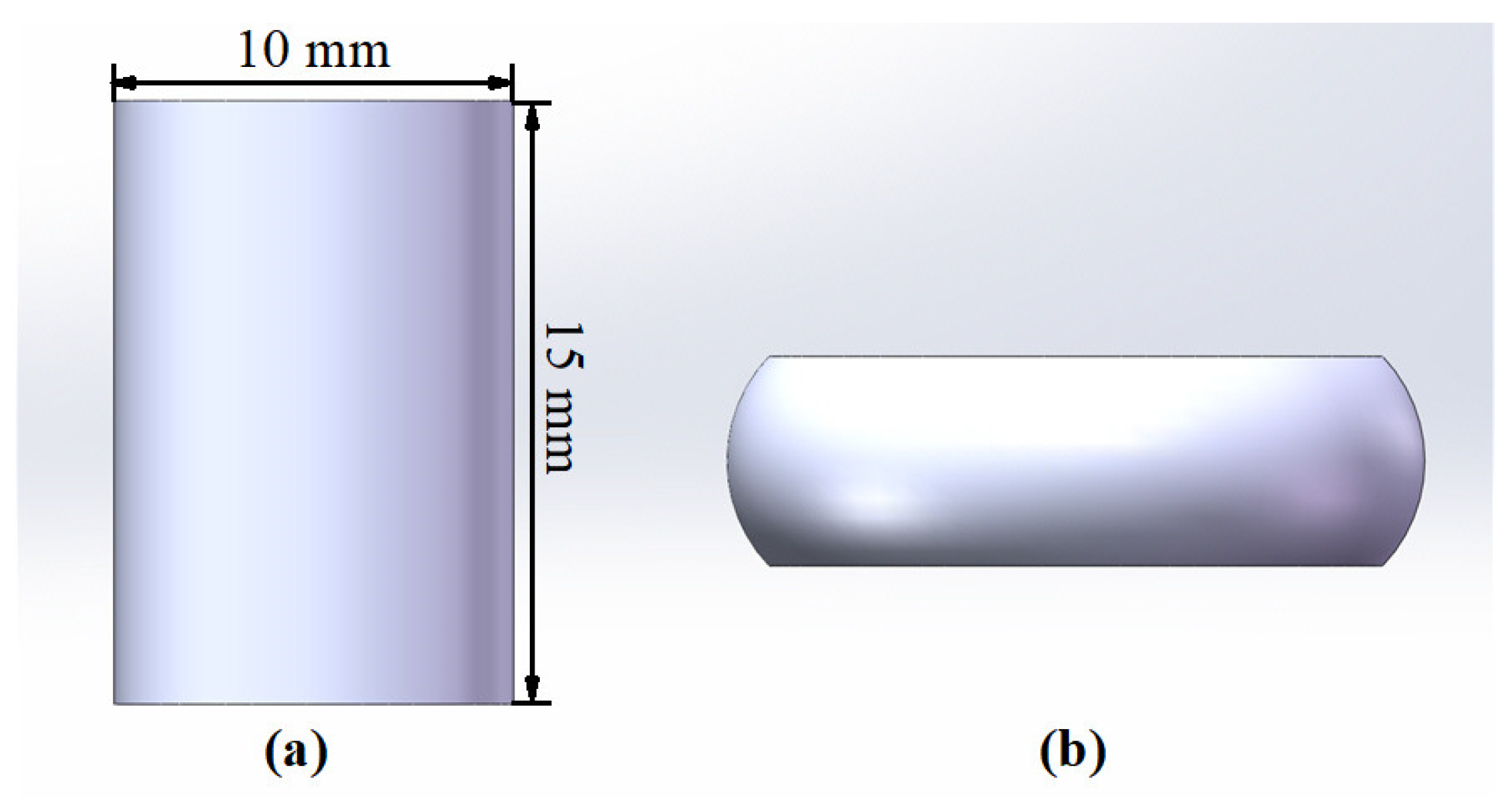
Figure 1. (a) The cylindrical specimen shape; (b) the compressed specimen shape.
Metals 13 00700 g001
Figure 2. Initial microstructure of AA7075 material.
Metals 13 00700 g002
Figure 3. Gleeble-3500 testing machine.
Metals 13 00700 g003
Figure 4. Temperature variation curve during hot compression tests.
Metals 13 00700 g004
Figure 5. The original and corrected stress–strain curves at different deformation temperatures: (a) 0.01 s−1; (b) 0.1 s−1; (c) 1s−1; (d) 10 s−1.
Metals 13 00700 g005
Figure 6. Data points and their fitted lines: (a) ln ε , ln e I 1 C 1 ; (b) ε , S 1 ; (c) T , P 1 .
Metals 13 00700 g006
Figure 7. Hot compression finite element model.
Metals 13 00700 g007
Figure 8. Calculated bulge coefficients under all deformation conditions.
Metals 13 00700 g008
Figure 9. The flowchart representing friction coefficient identification by inverse analysis technique.
Metals 13 00700 g009
Figure 10. Predicted friction coefficients under all deformation conditions.
Metals 13 00700 g010
Figure 11. Comparisons of experimental and simulated shapes (PEEQ: equivalent plastic strain): (a) “e” specimen; (b) “j” specimen.
Metals 13 00700 g011
Figure 12. Axial sections obtained by wire cutting to the compressed specimen.
Metals 13 00700 g012
Figure 13. The flowchart representing M-ZA model parameter identification by inverse analysis technique.
Metals 13 00700 g013
Figure 14. Variations in parameters with the number of iteration steps: (a)   E r r _ F ; (b) A A R E ; (c) C 1 ; (d) C 6 .
Metals 13 00700 g014
Figure 15. Comparisons of experimental and predicted compression force–displacement curves at different deformation temperatures: (a) 0.01 s−1; (b) 0.1 s−1; (c)1s−1; (d)10 s−1.
Metals 13 00700 g015
Figure 16. (a) Initial forging FE model; (b) final forging FE model.
Metals 13 00700 g016
Figure 17. (a) Final forging experiment; (b) one final forging.
Metals 13 00700 g017
Figure 18. (a) Load–stroke curves during initial forging process; (b) load–stroke curves during final forging process; A-F: the simulated material flow at different stages of the initial and final forging process.
Metals 13 00700 g018
Table 1. Chemical composition of AA7075 alloy (wt.%).
CompositionZnMgCuSiTiCrMnFeAl
Wt./%5.882.661.670.260.180.240.150.14Bal.
Table 2. Constitutive model parameters identified by linear fitting method.
C 1 (MPa) C 2 (MPa) C 3 C 4 C 5 C 6 n
77.3024.904.386 × 10−36.643 × 10−40.10284.420 × 10−47.605 × 10⁻²
Table 3. Thermo-physical parameters of AA7075 alloy.
Thermal
Conductivity
(W/(m·K))
Specific Heat
(J/(kg·K))
Density
(kg/m3)
Inelastic Heat
Fraction
13096028000.9
Table 4. Upper and lower boundaries for the nine model parameters.
Boundaries C 1 (MPa) C 2 (MPa) C 3 C 4 C 5 C 6 n T r e f log 10 ε ˙ r e f
Upper boundary5515000.050.00020300−2
Lower boundary98450.0060.0020.140.000734501
Table 5. The M-ZA model parameters identified by the inverse analysis method.
C 1 (MPa) C 2 (MPa) C 3 C 4 C 5 C 6 n T r e f ε ˙ r e f
79.1824.044.993 × 10−31.084 × 10−37.899 × 10−24.229 ×10−40.5460325.721.167 × 10−2
Table 6. Forging process parameters.
Billet
Diameter
Billet
Height
Billet
Temperature
Die
Temperature
Forging
Speed
Transfer Time
250 mm229 mm430 °C400 °C16 mm/s10 s
Disclaimer/Publisher’s Note: The statements, opinions and data contained in all publications are solely those of the individual author(s) and contributor(s) and not of MDPI and/or the editor(s). MDPI and/or the editor(s) disclaim responsibility for any injury to people or property resulting from any ideas, methods, instructions or products referred to in the content.