Article

Effects of Cold Expansion on Residual Stress of 7050 Aluminium Alloy Frame Forging

1
Light Alloy Research Institute, Central South University, Changsha 410083, China
2
State Key Laboratory of High Performance Complex Manufacturing, Central South University, Changsha 410083, China
3
College of Mechanical and Electrical Engineering, Central South University, Changsha 410083, China
*
Author to whom correspondence should be addressed.
Metals 2023, 13(4), 732; https://doi.org/10.3390/met13040732
Submission received: 22 March 2023 / Revised: 6 April 2023 / Accepted: 6 April 2023 / Published: 8 April 2023

Abstract

:
Regulation of residual stress in a component is the key to improving its service performance. A cold expansion method was proposed for reducing the residual stress in 7050 aluminium alloy curved frame forging after quenching. The effect of the cold expansion method on the residual stress and equivalent plastic strain distribution of the 7050 aluminium alloy curved frame forging was investigated. The results showed that the maximum residual stress at the center thickness was reduced from 153 MPa to 94 MPa after the cold expansion, while it decreased from 283 MPa to 120 MPa at the surface with the highest stress reduction rate of 86.2%. The stress uniformity in the final forming region of the forging was improved. The equivalent plastic strain of the forging gradually decreases from the center to each side along the diameter of the expanded hole in cold expansion. The stress reduction effect matched with the distribution of equivalent plastic strain. The surface stress of the forging measured by x-rays diffraction (XRD) method was in agreement with the simulation results, and the reliability of the numerical model was verified. The cold expansion method can effectively reduce the quenched residual stress in curved frame forging.

1. Introduction

The low weight of structural components is one of the critical problems in developing large aircraft, rockets, and spacecraft. The development and use of lightweight materials are the keys to this. High-strength aluminium alloys are widely used in aerospace applications because of their outstanding advantages such as low weight, high strength, corrosion resistance, good processing properties, and accessible surface treatment [1,2]. It is mainly used as a structural material in large carrier aircraft and accounts for over 70% of the total [3]. Most of the aluminium alloy components are designed to be thin-walled with a material removal rate of more than 90% after finishing [4,5] to meet the lightweight purpose. A 7000 series aluminium alloys have the advantages of high specific strength, high specific stiffness, high toughness, excellent processing, and welding properties [6]. They are often used in aircraft frames and other critical curved structures with high dimensional accuracy and excellent mechanical properties [7]. However, the dimensional stability of curved thin-walled components has been a problematic research area during machining. As a typical curved thin-walled component, the aircraft window frame is one of the critical components of aircraft. Its structural strength and dimensional stability are complex problems in research. It is also the key to determining whether a new breakthrough can be achieved in the development of large carrier aircraft. 7000 series aluminium alloy is used as a curved component of an aircraft window frame. It has to go through a series of processes such as billet forming, forging, heat treatment, cold deformation and machining, and every process has a crucial role in the final molding and performance [8]. The process of solution heat treatment, quenching and subsequent precipitation hardening is essential to strengthen 7000 series aluminium alloys and to achieve the formability required [9,10]. However, quenching introduces large residual stress into components [11,12,13]. During subsequent machining, the release of residual stress will directly affect the dimensional stability [12] and reduces the service life of the components [4]. Therefore, it is essential to relieve residual stress of curved forging after quenching.
In the field of residual stress reduction, a lot of research has been undertaken by scholars. G.H. Yang et al. [14] investigated the effect of 2A14 aluminium alloy on the evolution of residual stress in the stress field, temperature field and thermo-mechanical coupling conditions. The results show that the continuous increase of the external load leads to the increase of the residual stress of 2A14 aluminium alloy perpendicular to the tensile direction. The change of the residual stress is no longer significant when the external load approaches the yield strength; under the effect of temperature, the residual stress of 2A14 aluminium alloy decreases after the heating-holding-cooling process. The impact of over-ageing precipitation treatment on residual stress was studied by Robinson [15], and was shown to reduce the residual stress amplitude by 25–40%. The research by Godlewski [13] showed that the relaxation of residual stresses increased with increasing aging temperature; an aging temperature of 533 K used for 1 h could achieve a 50 pct reduction in residual stress in aluminium E319 alloy. Compared to the cold working techniques, the aging treatment could only reduce the residual stress by 40–50%. It was indicated that the vibration ageing treatment can reduce the residual stress and improve the dimensional stability of thin-walled 7075 aluminium alloy members [16]. A study by R. Pan [17] et al. investigated the effect on quenched residual stress in T-shaped aluminium alloy plates in terms of three aspects of the compression ratio, friction coefficient, and overlap length of the cold pressing process. Pan R. et al. [18] further investigated the quenched residual stress reduction of AA7050 aluminium alloy thick plates by cold compression method. By applying a compressive deformation of 1.5–3% to the aluminium alloy plate, the magnitude of residual stress could be reduced by 90%. Cozzolino and Luis [19] studied the residual stress in steel plates after welding, and partial rolling treatment was used to reduce the residual stress in the weld. Their study showed that partial rolling could effectively reduce the residual stress caused by welding. It was investigated by MR [20] the effect of edge distance ratio on the residual stress distribution in the cold reaming of 2024 aluminium alloy. When the edge distance ratio was less than 3, cold expansion had a significant effect on the residual stress distribution. Full-field in-plane residual strains and the out-of-plane surface deformations around open cold-expanded holes were measured by Amjad [21] in aluminium specimens of two different thicknesses giving thickness-to-diameter ratios of 0.25 and 1. The results show that the plastic deformation during cold expansion causes local out-of-plane deformation of the material near the hole’s edge, and deformation is more significant in specimens with a small thickness-to-diameter ratio. A study by Rahman [22] identified that cold expansion of prefabricated holes in AA5251 aluminium alloy plates could change the component’s residual stress field and enhance fatigue life.
In conclusion, the cold deformation method, an effective method for reducing residual stress, is widely used for various types of components. However, the reduction of residual stress in curved members, especially by the cold expansion method, has been rarely studied.
In this work, a circular hole cold expansion method was developed for the reduction of quenched residual stress in curved frame forging. A finite element numerical model was established to simulate the cold expansion process of curved frame forging; the distribution patterns of residual stress and equivalent plastic strains of curved frame forging after cold expansion were analyzed. Cold expansion experiments were conducted on the curved frame forging, and the surface stress of the forging before and after cold expansion was measured by the XRD method. The simulation and experiment results were discussed and compared discussed to verify the reliability of the numerical model. This work provides a new method for the residual stress reduction of curved frame forging.

2. Materials and Methods

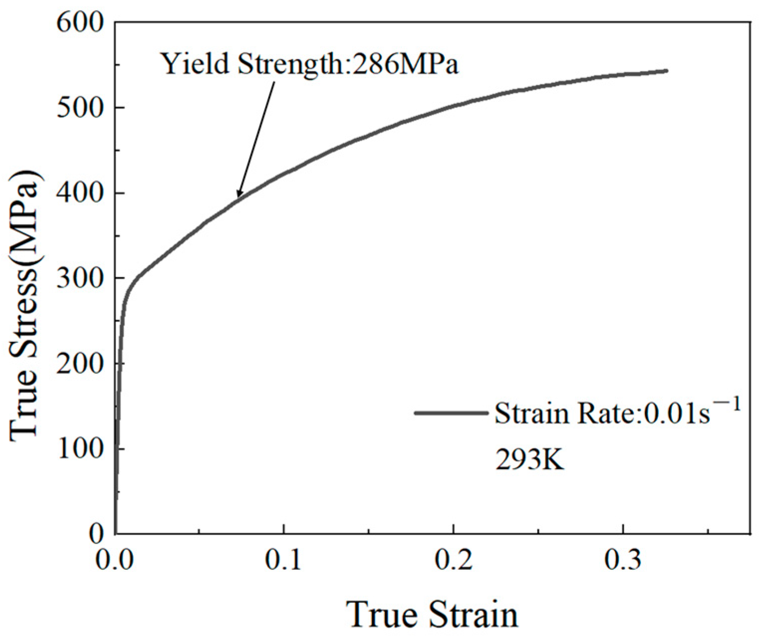
2.1. Material Parameters

Aluminium alloy is widely used in aviation, aerospace and weapons industries because of its better specific stiffness, specific strength, corrosion resistance and process ability. Especially in aerospace field, 7050 aluminium alloy is the most commonly used material because of its superior processing and welding properties. The chemical composition of 7050 aluminium alloy is listed in Table 1.
The mechanical behavior of the 7050 aluminium alloy was tested at a constant strain rate of 0.01 s −1 based on the actual cold expansion rate, as shown in Figure 1. At room temperature, the yield strength of 7050 aluminum alloy with a strain rate of 0.01 is 286 MPa, Young’s modulus is 75 GPa, and Poisson’s ratio is 0.3.

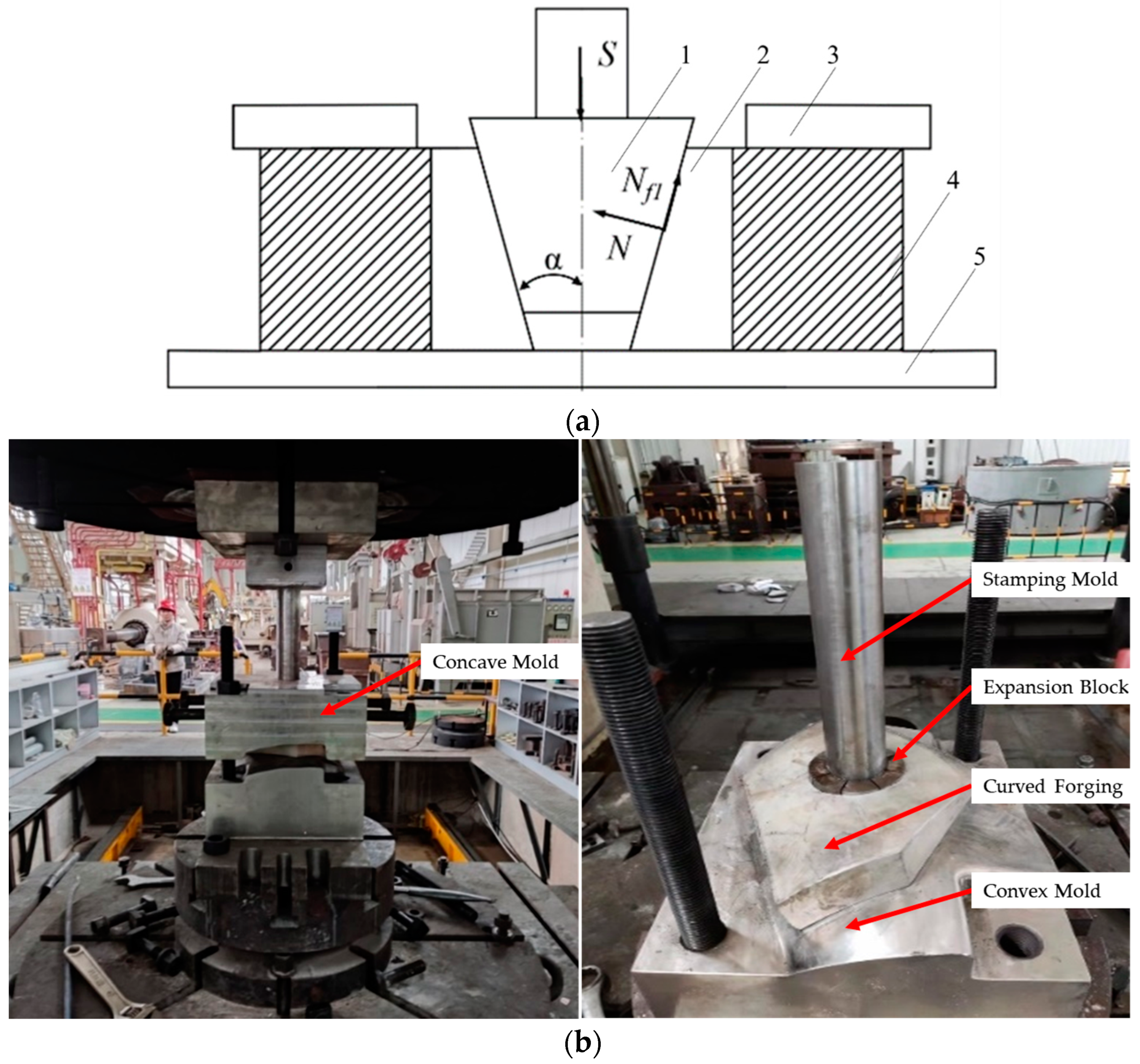
2.2. Cold Expansion Method

As shown in Figure 2, a cold expansion experiment was performed on the window frame forgings within 4 h after the quenching treatment, and the equipment used in the experiment was a 4000-ton forging machine. The basic steps are as follows.
(a)
Installation: install the convex mold, forging component, concave mold, stamping mold, and expansion block on the forging machine, and fix the convex and concave molds through bolts;
(b)
Loading: drive the forging machine to move vertically downward to the specified position and keep 30 s;
(c)
Unloading: the forging machine is slowly lifted up to unload the pressure;
(d)
Completion: loosen the fastening bolts and remove the forging part, the cold expansion process is completed.
Figure 2a is a schematic diagram of cold expansion; labels 1 to 5 represent stamping mold, expansion block, concave mold, curved frame forging, and convex mold.

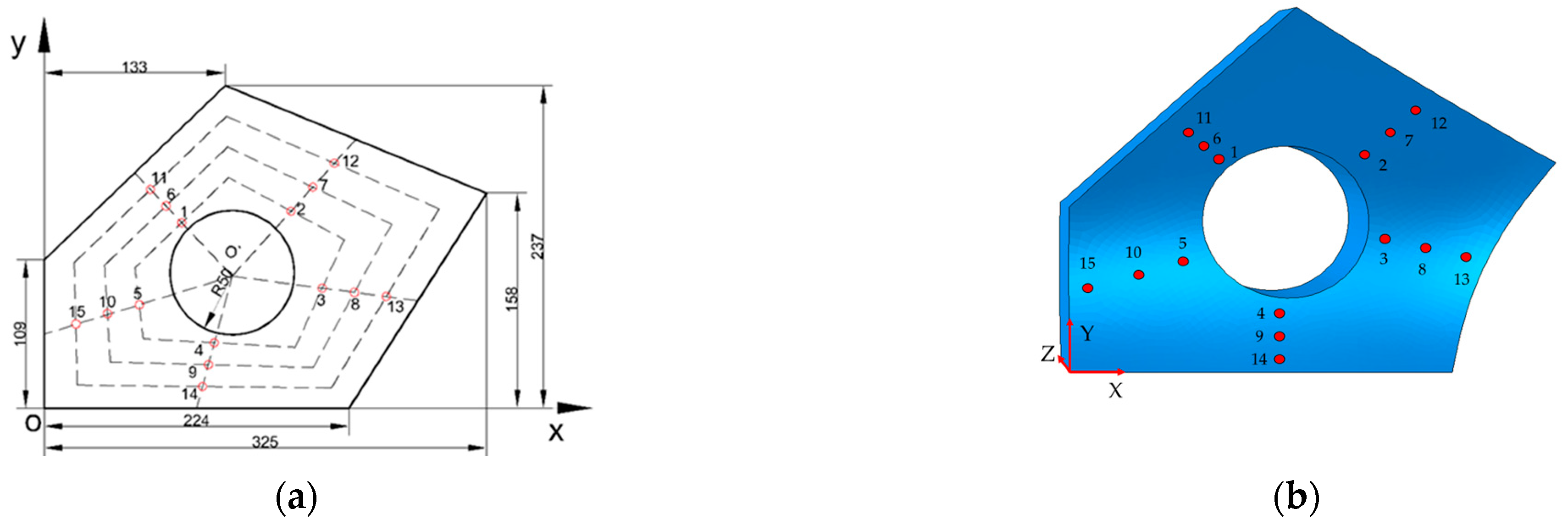
2.3. Residual Stress Measurement Method

Surface residual stress tests were performed on the forging within 4 h after the quenching process of the curved frame forging to obtain the residual stress distribution characteristics. A cold expansion experiment was performed on the curved frame forging, and its surface residual stress was re-examined.
Figure 3 depicts the projection of the curved frame forging in the XOY plane and the position of the XRD measurements points in forging. The thickness of the forging is 50 mm. A total of 15 test points were selected on the forgings, with 5 points selected for each circle. Points 1 to 5 were the first range, points 6 to 10 were the second range, and points 11 to 15 were the third range.
The surface of the forging was cleaned to prevent the surface oxidation layer from affecting the test results and marked the measured points; the X-ray diffractometer was started, warmed up, and set the parameters. Before measurement, the X-ray stress diffractometer was calibrated by measuring a stress-free coupon of 7050 aluminium alloy. Marked points of the window frame forging were tested, and the test crystal plane was 311. The residual stress on the surface of the curved frame forging before and after cold expansion was tested using an X-ray diffractometer. The parameters of the X-ray diffractometer are shown in Table 2.

3. Models Description

The residual stress analysis based on thermo-elastic-plastic (TEP) FEM was usually applied. In this section, the quenching and cold expansion process numerical models of the curved forging were established.

3.1. Quenching Model

The forging was heated to approximately 477 °C, held at temperature for 7 h. Then it was transferred to quench in water at 20 °C within 10 s. The forging entered the water along its thickness direction.
The finite element model of the curved forging quenching process was established using ABAQUS software. The eight-node linear hexahedral elements (HEX C3DR8T) were assigned to the whole model, and a coupled temperature-displacement analysis was performed. The mesh size was 5 mm × 5 mm × 5 mm.
The following assumptions were adopted in the quenching model:
(1)
The material of the curved frame forging is continuous and isotropic.
(2)
The initial temperature field distribution of the curved frame forging is uniform, and the initial residual stress is negligible.
(3)
The temperature of the quenching medium remains uniform.
(4)
The phase change of the curved frame forging during the quenching process is not considered.

3.2. Cold Expansion Numerical Modelling of Curved Frame Forging

After quenching, a numerical simulation model of the cold expansion process of the curved frame forging was established in ABAQUS by taking the calculated quenched residual stress as the predefined initial stress. The cold expansion model was shown in Figure 4, where the concave mold, forging, convex mold, and expansion block were in contact. The mesh type of the other instances (concave mold, convex mold, and expansion block) is a discrete rigid body with adaptive meshing. The residual stress distribution after cold expansion deformation ratios of 1%, 2%, and 3%, via the friction coefficient of 0.1, and the number of expansion blocks of 8, were predicted in numerical simulation.
The cold expansion simulation process includes four stages. In the first stage, the forging, expansion block and mold were assembled, and the initial boundary condition of the model was that the displacement components in X, Y and Z directions were 0. In the second stage, the expansion block is moved outward along the radial direction of the expansion hole, creating an extrusion force on the forging. In the third stage, the expansion block was moved inward along the radial direction of the expansion hole to the initial position of stage 2. In the fourth stage, the forging was unloaded from the molds.
The following assumptions were adopted in the cold expansion model:
(1)
The material of the curved frame forging is continuous and isotropic.
(2)
The friction coefficient between the curved frame forging and the mold is constant during the cold expansion process.
(3)
The temperature change of the curved frame forging during the cold expansion process is not considered.

4. Results and Discussion

The effectiveness of the cold expansion residual stress reduction technique has been evaluated by comparing the stress distributions in the curved frame forging after quenching and cold expansion. The residual stress reduction rates before and after cold expansion have been calculated. Moreover, the equivalent plastic strain of the forging was studied to analyze the effect of cold expansion on the deformation of the components after cold expansion. Finally, the reliability of the cold expansion model was verified by comparing the surface residual stress of the forging measured by XRD with the simulation results.

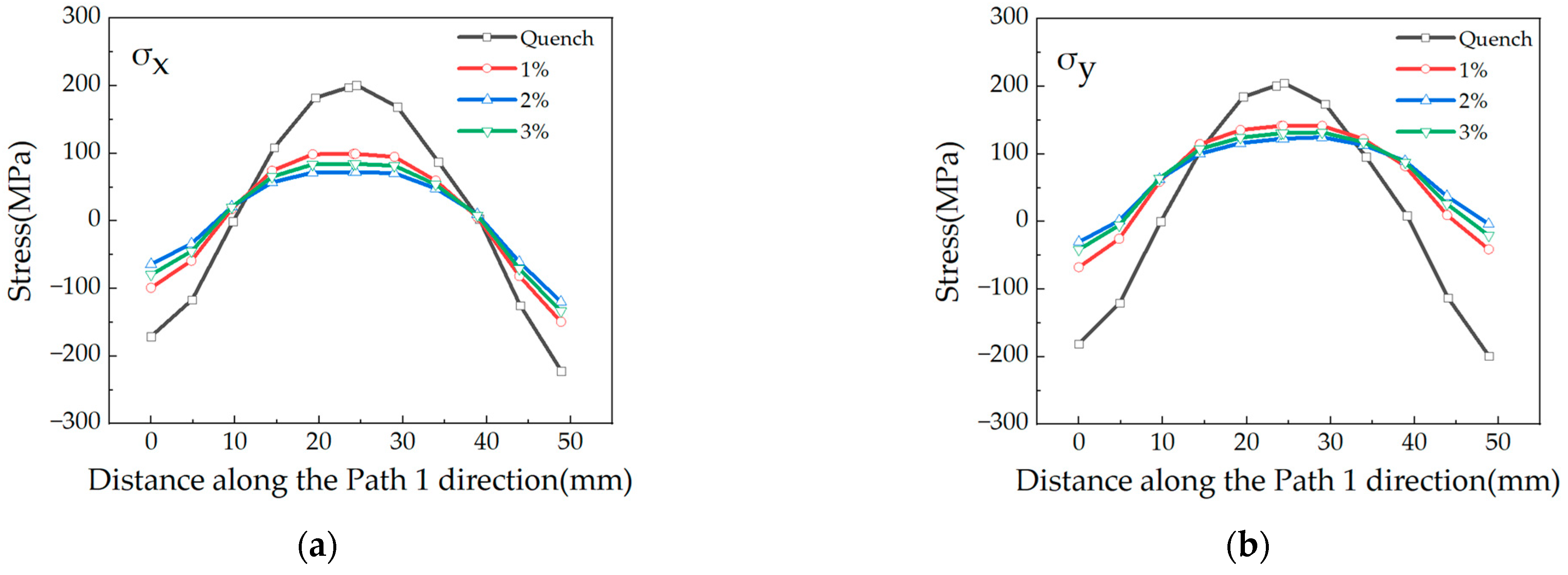
4.1. Effect of Cold Expansion Rate on Residual Stress

The cross-section was taken in the forging thickness direction through point 9, with the cross-section parallel to the YZ plane, as shown in Figure 5. The MN was taken as path 1 along the thickness direction, and the residual stress in this path was analyzed to demonstrate the effect of cold expansion rate on quenched stress.
The quenched residual stress in the forging was reduced to varying degrees after cold expansion. The distribution of stress in the X-direction (σx), Y-direction (σy), Z-direction (σz), and Mises was observed, as shown in Figure 6. The results revealed that 2% cold expansion rate of was most effective for reducing quenched residual stress. From the result, it could be seen that the magnitude of σz was within ±40 MPa, both before and after the cold expansion. However, after quenching, the stress amplitudes of σx and σy are relatively large. The forging surface exhibited compressive stress with a maximum compressive stress amplitude of 221 MPa, and the core exhibited tensile stress with a maximum tensile stress amplitude of 205 MPa. After cold expansion, the stress amplitudes of both σx and σy were reduced to varying degrees, but still exhibited surface compressive stress with a maximum compressive stress amplitude of 119 MPa, and core tensile stress with a maximum tensile stress amplitude of 125 MPa. After quenching, the von Mises stress along path 1 show a W-shaped distribution (larger values at the surface and in the core of the forging, and smaller values at the quarter thickness), with a maximum value of 227 MPa. After a 2% cold expansion process, the von Mises stress amplitude of the forgings was reduced to below 120 MPa.
The most effective ratio (2%) was subsequently used. The stress contour maps of the forging after quenching and cold expansion were shown in Figure 7. The distribution of von Mises stress could be seen in the maps. After quenching, the von Mises stress on the surface of the forging reached 283 MPa, and the von Mises stress in the center thickness of the forging reached 210 MPa. After quenching, the von Mises stress in the K region of the forging surface was above 260 MPa, and the von Mises stress value in the L region was above 220 MPa, as shown in Figure 7b. The K and L regions exhibited large stress, and the sum of the two areas occupied 2/3 of the convex surface. After the cold expansion, the von Mises stress on the surface of the forging was reduced significantly to below 120 MPa in most areas, as shown in Figure 7d. The von Mises stress in the K and L regions was effectively relieved. After quenching, it was observed that the stress in most areas of the central layer was below 210 MPa, and the stress did not exceed 80 MPa in the edge areas of the central layer shown in Figure 7a. After cold expansion, it was seen that the stress in most areas of the central layer of the forging was reduced to 135 MPa below, and the stress was displayed a circular distribution with an amplitude of 65 MPa or less in the area 14 mm to 38 mm from the expansion hole, as shown in Figure 7c.

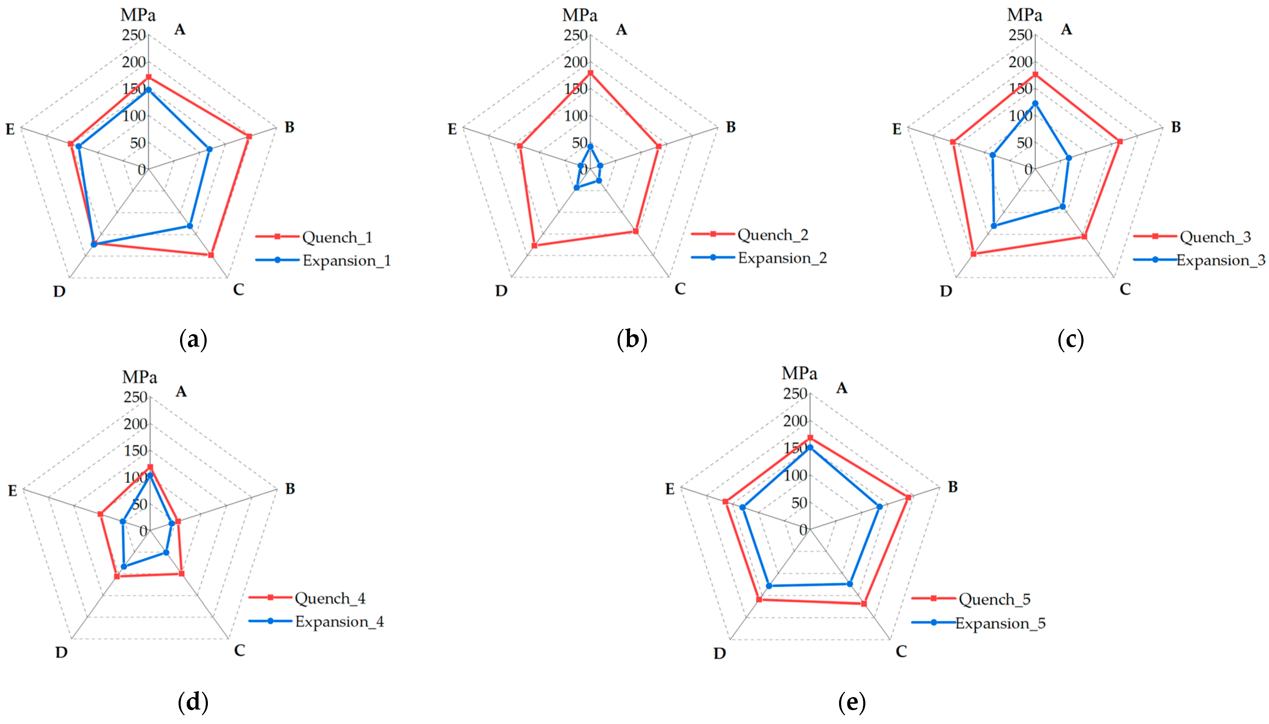
4.2. Residual Stress and Strain Fields after Cold Expansion

The effectiveness of the cold expansion residual stress reduction method was evaluated by comparing the stress distribution in curved frame forging after quenching and cold expansion. The forging was divided into five regions by five pentagons (P1, P2, P3, P4, P5) depending on the gradient of the von Mises stress cloud diagram. As in Figure 8, taking the intersection of O`A, O`B, O`C, O`D, O`E and P1, P2, P3, P4, and P5 at the center thickness of the forging, and von Mises stress radar maps were plotted after quenching and cold expansion of the forging as shown in Figure 9. Quench_1 represented the von Mises stress of region P1 after quenching, Expansion_1 represented the von Mises stress of region P1 after cold expansion, and so on. The ABCDE in the radar diagram corresponds to the ABCDE of the forgings.
As shown in Figure 9, the quenched von Mises stress in the central layer of the forging was larger in the P1, P3, and P5 regions, with a maximum value of 197 MPa; the quenched von Mises stress in the P4 region was smaller, below 120 MPa; the quenched von Mises stress amplitude in the P2 region was in between P4 and P3. After cold expansion, the von Mises stress amplitude in the P2 region decreased significantly from a maximum of 179 MPa to a maximum of 43 MPa. The von Mises stress amplitude in the P1, P3, P4, and P5 regions also decreased to some extent. However, the reduction effect in the P1 region was not satisfactory because it is in direct contact with the expansion block. Moreover, the stress reduction effect was poor in the O`A and O`D directions of the five regions. The distance between these two directions and the centre of the expanding hole was the farthest, and the effect of cold expansion was not obvious. After cold expansion, the von Mises stress in the centre thickness of the forging was reduced from an average of 153 MPa to an average of 94 MPa. The von Mises stress in the centre thickness of the forging was effectively relieved. Considering the stress uniformity in the final forming region of the forging, the standard deviation and the extreme deviation of the von Mises stress in the P5 region were calculated. The results indicated that the standard deviation of the quenched von Mises stress was 40.09 and the polar deviation was 134.23, while the standard deviation of the von Mises stress after cold expansion was 36.90 and the polar deviation was 107.99. After cold expansion, the stress uniformity in the P5 region of the forging was improved.
The equivalent plastic strain distribution of the curved frame forging after the cold expansion was obtained, as shown in Figure 10. To further discuss the plastic strain generated and the effect on stress reduction, the radar plot of the equivalent plastic strain after the cold expansion was plotted (Figure 11).
As shown in Figure 11, after cold expansion of the forging, the equivalent plastic strain gradually decreased from P1 to P5. The largest equivalent plastic strain was in the P1 region, with a maximum value of 3.2 × 10⁻². The P1 region was where the expansion hole was in contact with the expansion block, and the largest plastic deformation occurred in this region. The equivalent plastic strain in P2 is smaller than that in the P1 region but larger than that in the P3 region. The equivalent plastic strain in the P3 region was slightly larger than that in the P4 and P5 regions, and the equivalent plastic strain values in the P4 and P5 regions were both very small, less than 3.8 × 10⁻⁴.
In addition, we noticed that the equivalent plastic strain of the forging after the cold expansion was not uniformly distributed along the expansion aperture from the centre to each side. As in Figure 10, the path Ln (n = 1, 2, 3, 4, 5) was taken at the centre thickness of the forging to analyze the distribution of the equivalent plastic strain along it. The equivalent plastic strain distribution for the five paths of the forging in center thickness was shown in Figure 12. It was obvious that the equivalent plastic strains of L1, L3 and L4 decreased gradually from the expansion hole to each side of the forging; however, the equivalent plastic strains of L2 and L5 exhibited a decrease and then an increase. Moreover, we noticed that the distances from L2 and L5 paths along the expansion hole to the outer edge of the forging were 50.8 mm and 50.3 mm, respectively, a difference of less than 1%. However, the distances of L1, L3 and L4 paths were 86.6 mm, 72.3 mm and 73.2 mm, respectively, with differences of 70.5%, 42.3% and 44.1% from L2. We believed that the equivalent plastic strain of the forging after cold expansion had occurred in different distributions due to the different thicknesses of each path. Not only had plastic strain been accumulated in the area around the expanded hole, but plastic strain also penetrated the whole thickness in L2 and L5 directions, after cold expansion treatment.
In addition, we noticed that the equivalent plastic strain of the forging after the cold expansion was not uniformly distributed along the expansion aperture from the center to each side. As in Figure 10, the path Ln (n = 1, 2, 3, 4, 5) was taken at the center thickness of the forging to analyze the distribution of the equivalent plastic strain along it. The equivalent plastic strain distribution for the five paths of the forging in center thickness was shown in Figure 12. It was obvious that the equivalent plastic strains of L1, L3 and L4 decreased gradually from the expansion hole to each side of the forging; however, the equivalent plastic strains of L2 and L5 exhibited a decrease and then an increase. Moreover, we noticed that the distances from L2 and L5 paths along the expansion hole to the outer edge of the forging were 50.8 mm and 50.3 mm, respectively, a difference of less than 1%. However, the distances of L1, L3 and L4 paths were 86.6 mm, 72.3 mm and 73.2 mm, respectively, with differences of 70.5%, 42.3% and 44.1% from L2. We believed that the equivalent plastic strain of the forging after cold expansion had occurred in different distributions due to the different thicknesses of each path. Not only had plastic strain been accumulated in the area around the expanded hole, but plastic strain also penetrated the whole thickness in L2 and L5 directions, after cold expansion treatment.
The von Mises stress in the centre thickness of the forging had been reduced after cold expansion. The intersection points of O`A, O`B, O`C, O`D, O`E, and P1, P2, P3, P4, P5 at the centre thickness of the forging were taken to obtain the residual stress magnitude, and the residual stress reduction rate was calculated (Figure 13).
The stress reduction rate could be expressed by Equation (1).
δ = R S q R S e R S q × 100 %
δ —Reduction rate;
R S q —Residual stress before cold expansion;
R S e —Residual stress after cold expansion.
It can be observed from Figure 13 that the von Mises stress reduction rate was maximum in the P2 region in the centre thickness of the forging. Although the equivalent plastic strain in the P1 region is significantly larger than that in the P2 region, the stress reduction rate in the P1 region was significantly smaller than that in the P2 region. In the P1 region, the forging was in direct contact with the expansion block, and although significant plastic deformation occurs in this region after cold expansion, the stress was poorly relieved. The von Mises stress of the forging in the P2, P3 and P4 regions was effectively relieved; especially in the P2 region, the stress reduction rate was above 75%, with the highest reaching 86.2%. Before cold expansion, the von Mises stress amplitude in the P2 and P3 regions was large. After cold expansion, the stress in these regions was validly relieved, and the uniformity of the overall stress distribution of the forging was improved.

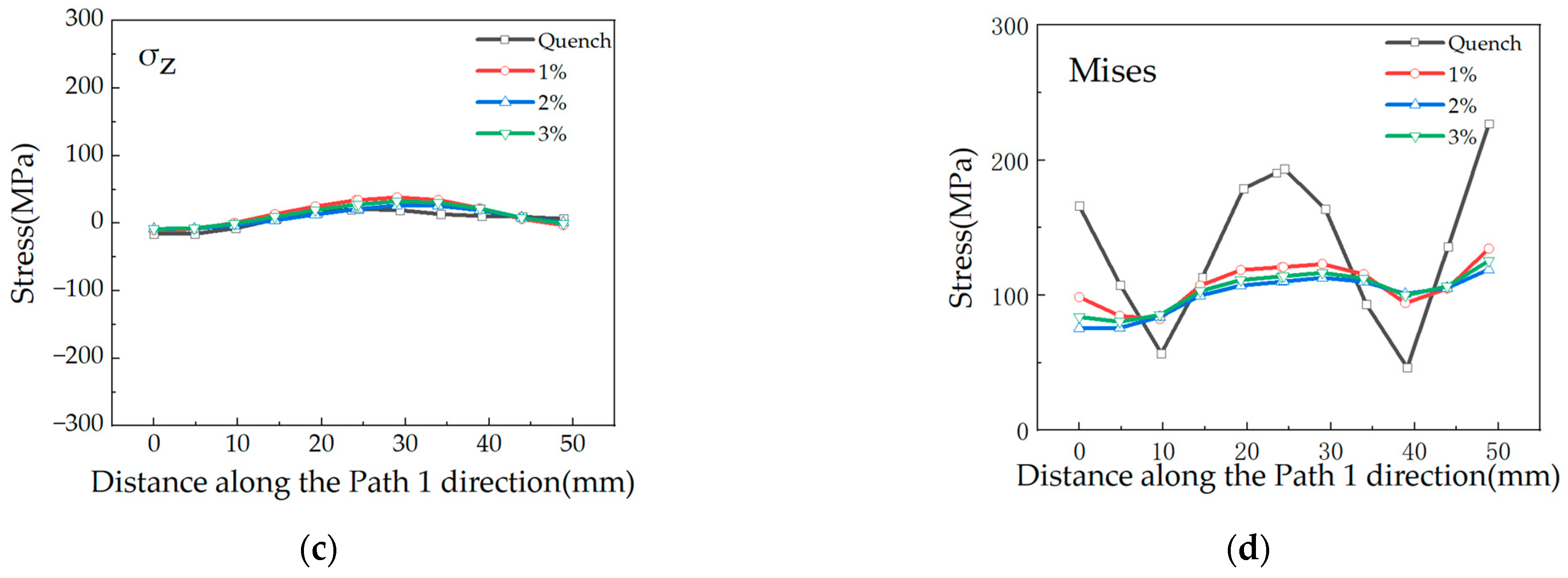
4.3. Results Verification

The X-directional stress on the surface of the forging before and after the cold expan-sion was measured by XRD. The X-directional stress at points 1 to 15 on the forging surface was obtained from the numerical model, compared with the experimental measurement results, and plotted in Figure 14. The experimental results show that the X-directional stress on the surface of the forging is reduced from a maximum of −194 MPa to −109 MPa after cold expansion. After cold expansion, the surface residual stress of forging is significantly reduced. After quenching, the average error between the measured and simulated values was 14.4%. After cold expansion, the average error between the measured and simulated values was 12.2%. There was a general agreement between the simulation results and measurements in terms of distribution trend and amplitude, which validated the reliability of the numerical model.

5. Conclusions

A cold expansion method, which was used to reduce the residual stress of curved frame forging, was proposed. Subsequently, a numerical model was developed to simulate the cold expansion process of curved frame forging. The effect of cold expansion method on the residual stress and equivalent plastic strain distribution of frame forging was investigated. The main conclusions were as follows.
(1)
The quenched numerical model results revealed that the quenched residual stress on the surface of the forging was up to 283 MPa, and the residual stress in the central layer was up to 210 MPa, which left a significant safety hazard for the subsequent processing.
(2)
The numerical results indicated that cold water quenching the 7050 aluminium alloy frame forgings led to large magnitude residual stress that varied from surface compression (up to 221 MPa) to tension in the core over 205 MPa. After cold expansion, the maximum compressive stress was reduced to 119 MPa, and the maximum tensile stress was reduced to 125 MPa. 2% cold expansion rate was the most efficiently for the reduction of quenched residual stress.
(3)
After 2% cold expansion, the residual stress in the forgings was effectively relieved. The von Mises stress on the surface was reduced from 283 MPa to 120 MPa; the von Mises stress at the central thickness was reduced from 153 MPa to 94 MPa. The stress uniformity in the final forming region of the forging was improved.
(4)
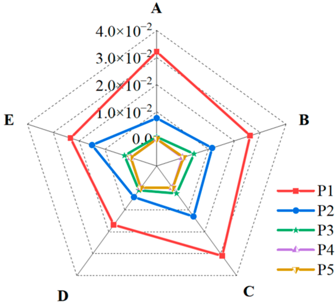
After cold expansion, extensive plastic deformation occurred in the vast majority of the area near the cold expansion hole, with a maximum plastic strain of 0.032 and a deformation of 0.013 in the smaller areas; the plastic strain in the area of the forging near each side was not significant. The equivalent plastic strain of the forging decreased gradually along the diameter of the expansion hole from the center to each side. However, in the two directions of the minimum thickness, the plastic strain decreased and then increased.
(5)
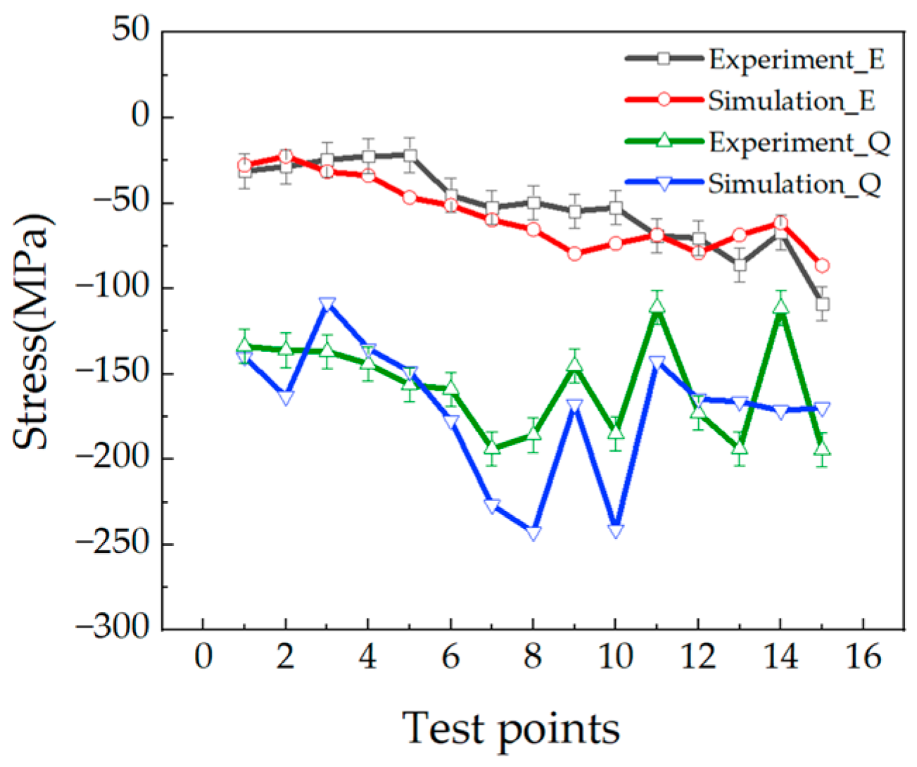
After cold expansion, the highest stress reduction rate of 86.2% was achieved in the region of 0.013 equivalent plastic strain at the center thickness of the forging; the stress reduction effect matched with the distribution of equivalent plastic strain. The XRD method was used to measure the surface stress of the forging after cold expansion, and the distribution was a general agreement with the numerical simulation results, which verified the reliability of the numerical model.

Author Contributions

Conceptualization: H.G., X.S. and T.Z.; Validation: H.G., X.S. and H.T.; Formal analysis: X.S. and H.T.; Investigation: H.G., X.S., T.Z. and H.T.; Writing—Review and Editing: H.G., X.S. and T.Z.; Supervision: T.Z. All authors have read and agreed to the published version of the manuscript.

Funding

This research was funded by the National Natural Science Foundation of China (Grant Number 51327902) and State Key Laboratory of High Performance and Complex Manufacturing (Grant Number ZZYJKT2022-04).

Data Availability Statement

The data presented in this study are available on request from the corresponding author.

Acknowledgments

We want to thank Yunxin Wu and Kang Chen for they support and help during the experimental work.

Conflicts of Interest

The authors declare no conflict of interest.

References

  1. Zhang, Y.Q.; Jiang, S.Y.; Zhao, Y.N.; Shan, D.B. Isothermal precision forging of complex-shape rotating disk of aluminum alloy based on processing map and digitized technology. Mater. Sci. Eng. A-Struct. Mater. Prop. Microstruct. Process. 2013, 580, 294–304. [Google Scholar] [CrossRef]
  2. Hu, H.E.; Wang, X.Y. Effect of Heat Treatment on the In-Plane Anisotropy of As-Rolled 7050 Aluminum Alloy. Metals 2016, 6, 79. [Google Scholar] [CrossRef]
  3. Miturska, I. Impact of assembly method on the strength of single-lap joints of aircraft aluminum alloy sheets. Adv. Sci. Technol. Res. J. 2020, 14, 163–170. [Google Scholar] [CrossRef]
  4. Huang, X.M.; Sun, J.; Li, J.F. Effect of Initial Residual Stress and Machining-Induced Residual Stress on the Deformation of Aluminium Alloy Plate. Strojniski Vestn.-J. Mech. Eng. 2015, 61, 131–137. [Google Scholar] [CrossRef]
  5. Shan, D.; Xu, W.; Si, C.; Lu, Y. Research on local loading method for an aluminium-alloy hatch with cross ribs and thin webs. J. Mater. Process. Technol. 2007, 187, 480–485. [Google Scholar] [CrossRef]
  6. Zhang, Y.; Shan, D.; Xu, F. Flow lines control of disk structure with complex shape in isothermal precision forging. J. Mater. Process. Technol. 2009, 209, 745–753. [Google Scholar] [CrossRef]
  7. Zhou, B.; Liu, B.; Zhang, S.G. The Advancement of 7XXX Series Aluminum Alloys for Aircraft Structures: A Review. Metals 2021, 11, 718. [Google Scholar] [CrossRef]
  8. Zheng, J.H.; Lin, J.G.; Lee, J.; Pan, R.; Li, C.; Davies, C.M. A novel constitutive model for multi-step stress relaxation ageing of a pre-strained 7xxx series alloy. Int. J. Plast. 2018, 106, 31–47. [Google Scholar] [CrossRef]
  9. Liu, Q.; Chen, S.C.; Gu, R.Y.; Wang, W.R.; Wei, X.C. Effect of Heat Treatment Conditions on Mechanical Properties and Precipitates in Sheet Metal Hot Stamping of 7075 Aluminum Alloy. J. Mater. Eng. Perform. 2018, 27, 4423–4436. [Google Scholar] [CrossRef]
  10. Xie, P.; Chen, K.H.; Chen, S.Y.; Ye, S.P.; Jiao, H.B.; Huang, L.P. Study on quenching sensitivity of 7097 aluminum alloy. Mater. Res. Express 2020, 7, 14. [Google Scholar] [CrossRef]
  11. Weng, Z.J.; Liu, X.Z.; Gu, K.X.; Guo, J.; Cui, C.; Wang, J.J. Modification of residual stress and microstructure in aluminium alloy by cryogenic treatment. Mater. Sci. Technol. 2020, 36, 1547–1555. [Google Scholar] [CrossRef]
  12. Singh, A.; Agrawal, A. Investigation of surface residual stress distribution in deformation machining process for aluminum alloy. J. Mater. Process. Technol. 2015, 225, 195–202. [Google Scholar] [CrossRef]
  13. Godlewski, L.A.; Su, X.M.; Pollock, T.M.; Allison, J.E. The Effect of Aging on the Relaxation of Residual Stress in Cast Aluminum. Metall. Mater. Trans. A-Phys. Metall. Mater. Sci. 2013, 44A, 4809–4818. [Google Scholar] [CrossRef]
  14. Yang, G.H.; Xue, B.; Li, Z.Y.; Zhou, G.; Zhang, S.H.; Lu, N.; Wen, L.; Zhang, D.Z. Influence of Stress Field and Temperature Field on Residual Stress of 2A14 Aluminum Alloy Based on In Situ SAXS Method. Materials 2023, 16, 170. [Google Scholar] [CrossRef]
  15. Robinson, J.S.; Pirling, T.; Truman, C.E.; Panzner, T. Residual stress relief in the aluminium alloy 7075. Mater. Sci. Technol. 2017, 33, 1765–1775. [Google Scholar] [CrossRef]
  16. Gong, H.; Sun, Y.J.; Liu, Y.Q.; Wu, Y.X.; He, Y.P.; Sun, X.L.; Zhang, M.H. Effect of Vibration Stress Relief on the Shape Stability of Aluminum Alloy 7075 Thin-Walled Parts. Metals 2019, 9, 27. [Google Scholar] [CrossRef]
  17. Pan, R.; Shi, Z.S.; Davies, C.M.; Li, C.; Kaye, M.; Lin, J.G. An integrated model to predict residual stress reduction by multiple cold forging operations in extra-large AA7050 T-section panels. Proc. Inst. Mech. Eng. Part B-J. Eng. Manuf. 2018, 232, 1319–1330. [Google Scholar] [CrossRef]
  18. Pan, R.; Pirling, T.; Zheng, J.H.; Lin, J.G.; Davies, C.M. Quantification of thermal residual stresses relaxation in AA7xxx aluminium alloy through cold rolling. J. Mater. Process. Technol. 2019, 264, 454–468. [Google Scholar] [CrossRef]
  19. Cozzolino, L.D.; Coules, H.E.; Colegrove, P.A.; Wen, S.W. Investigation of post-weld rolling methods to reduce residual stress and distortion. J. Mater. Process. Technol. 2017, 247, 243–256. [Google Scholar] [CrossRef]
  20. Ayatollahi, M.R.; Nik, M.A. Edge distance effects on residual stress distribution around a cold expanded hole in Al 2024 alloy. Comput. Mater. Sci. 2009, 45, 1134–1141. [Google Scholar] [CrossRef]
  21. Amjad, K.; Wang, W.C.; Patterson, E. A comparison of split sleeve cold expansion in thick and thin plates. J. Strain Anal. Eng. Des. 2016, 51, 375–386. [Google Scholar] [CrossRef]
  22. Seifi, R. Total fatigue lives, crack growth paths and cycles in cold expanded adjacent holes. Int. J. Fatigue 2018, 113, 69–77. [Google Scholar] [CrossRef]
Figure 1. Stress-strain curve of 7050 aluminium alloy at a constant temperature of 293 K and a constant strain rate of 0.01 s −1.
Metals 13 00732 g001
Figure 2. Cold expansion of forging: (a) schematic diagram: 1—stamping mold; 2—expansion block; 3—concave mold; 4—curved frame forging; 5—convex mold; (b) experiment.
Metals 13 00732 g002
Figure 3. Residual stress test: (a) a projection of the forging in the XOY plane; (b) the position of the XRD measurement points in forging.
Metals 13 00732 g003
Figure 4. Simulation model of cold expansion.
Metals 13 00732 g004
Figure 5. The analysis location of cold expansion rate on quenched residual stress in the forging.
Metals 13 00732 g005
Figure 6. Effect of cold expansion ratio on quenched stress of the forging: (a) stress in X-direction; (b) stress in Y-direction; (c) stress in Z-direction; (d) von Mises stress.
Metals 13 00732 g006aMetals 13 00732 g006b
Figure 7. Stress contour diagram of the curved frame forging after quenching and cold expansion: (a) von Mises stress in the center thickness of the forging after quenching; (b) von Mises stress on the surface of the forging after quenching; (c) von Mises stress in the center thickness of the forging after cold expansion; (d) von Mises stress on the surface of the forging after cold expansion.
Metals 13 00732 g007
Figure 8. The region of von Mises stress.
Metals 13 00732 g008
Figure 9. Von Mises stress after quenching and cold expansion of the central layer forging: (a) von Mises stress in region P1; (b) von Mises stress in region P2; (c) von Mises stress in region P3; (d) von Mises stress in region P4; (e) von Mises stress in region P5.
Metals 13 00732 g009
Figure 10. Equivalent plastic strain map of the forging after cold expansion.
Metals 13 00732 g010
Figure 11. Equivalent plastic strain of the forging.
Metals 13 00732 g011
Figure 12. Equivalent plastic strain in the centre layer of the forging in the direction of the diameter of the expanded hole.
Metals 13 00732 g012
Figure 13. Von Mises stress reduction rate in the centre thickness of the forging.
Metals 13 00732 g013
Figure 14. Comparison of the experimental data and the simulated results. Experiment_E is the measured stress after cold expansion; Simulation_E is the simulated stress after cold expansion; Experiment_Q is the measured stress before cold expansion; and Simulation_Q is the simulated stress before cold expansion.
Metals 13 00732 g014
Table 1. The chemical composition of 7050 aluminium alloy.
ElementZnMgCuZrFeSiTiMnAl
wt.%5.7–6.71.9–2.62.0–2.60.08–0.1150–0.15≤0.12≤0.12≤0.10Bal.
Table 2. XRD measurement parameters.
X-ray Diffraction ParametersSpecification/Values
Tube typeCr
Supplied current during the experiment6.7 mA
Supplied voltage during the experiment30 kV
Exposure time for the calibration8 s
Exposure time for measurement10 s
Collimator diameter2 mm
Collimator distance10.390 mm
Detector distance50 mm
Tilt angle−45° to 45°
Number of tilts5/5
Rotation angle0° to 90°
Number of rotations2
Stress resolution±10 MPa
Disclaimer/Publisher’s Note: The statements, opinions and data contained in all publications are solely those of the individual author(s) and contributor(s) and not of MDPI and/or the editor(s). MDPI and/or the editor(s) disclaim responsibility for any injury to people or property resulting from any ideas, methods, instructions or products referred to in the content.

