Article

Effect of Standing Time after Mixing on the Mixture Microstructure of an Al-Si Alloy during Controlled Diffusion Solidification with Simultaneous Mixing

State Key Laboratory of Advanced processing and Recycling of Nonferrous Metals, Lanzhou University of Technology, Lanzhou 730050, China
*
Author to whom correspondence should be addressed.
Metals 2023, 13(4), 733; https://doi.org/10.3390/met13040733
Submission received: 17 March 2023 / Revised: 7 April 2023 / Accepted: 7 April 2023 / Published: 9 April 2023
(This article belongs to the Section Metal Casting, Forming and Heat Treatment)

Abstract

:
Taking pure Al (938.15 K) and Al-12Si (858.15 K) melts as two precursors and the Al-8Si alloy as the target alloy, the effect of the standing time after mixing on the microstructure of a mixture during controlled diffusion solidification with simultaneous mixing was investigated via a simulation and experiment. The simulation results indicate that the entrapped air will promptly form bubbles and cause the mixture to overflow within a short time of 1.2 s. An effective blending action still occurs during the initial stage (i.e., 0–0.5 s) of the standing process, resulting in the significant homogenization of the temperature field due to the thermal conductivity being much higher than the solute diffusivity. This is due to the large difference between the two thermophysical parameters, causing nuclei to rapidly form in the pure Al melt close to the interface of the pure Al/Al-12Si melts during mixing. Some of the nuclei will remelt, and others will only grow towards the pure Al melt side in a stable solid/liquid interface during standing, resulting in nondendritic Al grains and an increase in their size but a decrease in their number. These changing tendencies of grain morphology, size and number due to the standing time are consistent with those from the experiment, implying the employed simulation and calculation, as well as the achieved results, are reasonable and reliable.

1. Introduction

Al alloys have many advantages, such as being lightweight and low cost, as well as having abundant resources, high thermal conductivity and good corrosion resistance; thus, they have been widely applied in automobile, aerospace, electronic information and sport equipment fields, in which weight loss is considered as one of the most important goals [1,2]. However, shrinkage porosities are inevitable in the Al alloy castings prepared by traditional casting technologies [3]. In addition, the casting processing of wrought Al alloys is always a target for researchers because of the difficulty of avoiding hot cracks in the resulting castings [4,5]. In essence, the formation of these two types of defects is attributed to the dendritic solidification behavior during the casting process [3,5,6]. Therefore, achieving a microstructure with small nondendritic grains can avoid or at least decrease these defects.
Thus far, two types of technologies have been developed to obtain a nondendritic solidification microstructure: semisolid forming and controlled diffusion solidification (CDS). For semisolid forming, a nondendritic slurry for rheoforming or nondendritic ingot for thixoforming should be prepared prior to the forming process by using special technologies [7,8,9]. Therefore, this technique is quite complicated, and the achieved castings are relatively costly. In contrast, the CDS process is quite simple, in which one precursor alloy melt (Alloy 1) with a high thermal mass (HTM; high temperature and large mass) is poured into another precursor alloy melt (Alloy 2) with a low thermal mass (LTM) to obtain the target alloy mixture, and then the mixture is immediately cast [10,11]. Saha et al. used the CDS technology to successfully produce commercial Al-Zn, Al-Mg, and Al-Cu aluminum alloy castings with a fine nondendritic grain structure, where the net-shaped wrought alloy castings particularly had high integrity and free hot cracks, and where their mechanical properties were equivalent to or even higher than those of the corresponding counterparts prepared with plastic deformation processing technologies [1,12]. Thus, CDS has great potential for use in engineering applications.
According to the available investigations on CDS, the resulting mixture from the two precursor alloy melts (Alloy 1 and Alloy 2) is composed of numerous small pockets of both precursor melts. Then, nuclei rapidly generate in the Alloy 1 pockets due to rapid chilling by the surrounding Alloy 2 pockets, which subsequently grow in a stable solid/liquid interface without constitutional supercooling due to the back-diffusion of solutes in the Alloy 2 pockets towards the solid/liquid interface. As this is opposite to the process of conventional solidification, it leads to the formation of small nondendritic primary grains [10,11,13]. Existing investigations have suggested several requirements for CDS to successfully achieve a casting with small spherical primary grains, which mainly include: (1) the mass ratio of Alloy 1/Alloy 2 is larger than 3; (2) the temperatures of the two precursor melts should be controlled within several superheat degrees (less than 10 K); and (3) the temperature difference between the two precursor melts is higher than 50 K [14,15,16,17]. The aim of requirement (1) is to achieve a mixture with uniform composition at the macroscale but a heterogeneous composition at the microscale (i.e., forming many small Alloy 1 pockets), whereas requirements (2) and (3) are meant to obtain a large supercooling degree in the Alloy 1 pockets within a short time. Under these conditions, many nuclei can be generated during mixing. Unfortunately, even if these requirements are all satisfied, anomalously coarse and irregular grains are always inevitable in the resultant castings [18]. The reason for the forming of such grains is attributed to the undesirable blending resulting from the employed mixing method. The formation of such grains can be restrained to some extent by decreasing the mixing rate [19], but this will decrease productivity. In addition, some composition alloys cannot be cast due to the requirement limitation (1).
In order to overcome the shortcomings mentioned above, the authors propose a modified CDS technique in which two precursor melts are simultaneously mixed at their respective pouring rates, the two melts converge in the air and fall into a crucible, and finally, the resulting mixture is poured [6]. The results indicated that when pure Al (Alloy 1) and Al-12Si (wt.%, Alloy 2) melts were mixed to produce an Al-8Si alloy casting at a mass ratio of 1:2, a casting with fine spherical primary grains was obtained, and no anomalous grains were observed [6]. The used mass ratio (1:2) was considerably smaller than 3, and more importantly, the results indicated that the higher the mixing rate, the smaller and more spheroidal the primary grains [6]. That is, this modified CDS technique should have more promising potential in engineering applications.
As discussed above, the available investigations have performed quite comprehensive studies on the mechanisms for forming a fine nondendritic microstructure, such as on the nucleation, subsequent growth mode and resultant morphology of primary grains during CDS, as well as on the influencing factors, such as the temperatures and compositions of the two precursor melts, the mass ratio and the mixing rate, and on the corresponding influencing mechanisms; therefore, some important achievements have been obtained [6,20,21]. However, the standing process of the mixture prior to pouring should also be an important parameter of CDS, as mentioned above. Still, only some ambiguous words or phrases, such as “immediately” [22] and “rapidly” [10,11], have been previously used to describe the standing process, and there has been no detailed investigation focusing on its effect on the final microstructure. Therefore, taking pure Al and Al-12Si alloys as precursor alloys and Al-8Si as the final target alloy in this work, the effects of the standing time after mixing on the temperature and the solute fields in the resulting melt mixture were first investigated by simulation and theoretical calculation to understand the nucleation, growth mode and morphology of primary grains. Experiments were then conducted to partially confirm the results from the simulation and calculation by observing the microstructures of water-quenched specimens.

2. Investigation Process

2.1. Simulation and Calculation Processes

As stated above, pure Al and Al-12Si alloys were selected as Alloy 1 and Alloy 2 to form the target Al-8Si alloy (Alloy 3). Fluent software simulated the mixing process (Fluent 2020R1, Ansys Inc., Pittsburgh, PA, USA), and the detailed process was the same as described in [6]. The dimensions of the used model are marked in Figure 1a, which were half of those of the equipment used in the latter experiment to save calculation time. In order to improve the simulation accuracy, the mesh sizes in the model (ranging from 0.88 mm to 2.125 mm) were much smaller than those in [6]. In addition to the continuity equation (mass conservation equation), the Navier–Stokes equation (momentum conservation equation) and energy conservation equation, expressed by Equations (1)–(5) mentioned in [6], demonstrates that solute diffusion was taken into account in this work, which is represented by Equation (1) [22,23]. The symbol C in Equation (1) refers to the solute concentration (wt.%), and the liquidus temperatures (TLiq) of pure Al and Al-12Si were 933.15 K and 853.15 K, respectively, which were obtained from the JMatPro software database (JMatPro 9.0, Sente Software Corporation, Guildford, UK). The meanings of the other symbols in the related equations and the values of the involved thermophysical parameters are the same as those in [6].
C t + u C x + v C y + w C z = D 2 C x 2 + 2 C y 2 + 2 C z 2
The temperatures of pure Al (Alloy 1) and Al-12Si (Alloy 2) were 938.15 K and 858.15 K, respectively, as shown by Figure 1b (the phase diagram was drawn using the FactSage software, FactSage 7.0, Montreal, QC, Canada), i.e., the superheating of the two precursor melts both occurred at 5 K, and the temperature difference was 80 K. To achieve the Al-8Si target alloy (Alloy 3), the mass ratio of pure Al/Al-12Si should be 1:2. In the simulation, the masses of the pure Al and Al-12Si melts were 1/3 kg and 2/3 kg, respectively, i.e., a 1 kg Al-8Si melt was achieved after mixing. During mixing, the two precursor melts were simultaneously poured within 1 s at their respective constant pouring rates. The standing time began as soon as all the melt completely fell into the Alloy 3 melt pool, and the statuses from 0 s to 1.2 s were simulated based on the computing power of the employed workstation. According to the simulation results, the average temperature of the resultant mixture was 883.56 K (Figure 1b), and thus, the temperature of the crucible that contains the mixture (Alloy 3) was set at this temperature.
With respect to nucleation during the standing process, it was assumed that once the temperature of one mesh with composition C (the concentration of Si) fell below the liquidus temperature, it then solidified. As expected, the greater the number of solidified meshes, the larger the nucleation rate. Therefore, the variation tendency of the nucleation rate due to the standing time can be estimated by the number percentages of solidified meshes at different standing times. By fitting the liquidus temperature of the hypoeutectic Al–Si alloy in Figure 1b using MATLAB software (MATLAB 9.11, MathWorks, Inc., Portola Valley, CA, USA), the variation in the TLiq with a Si concentration C can be achieved, which is expressed by Equation (2).
T L i q = 1980600 × C 5 - 627730 × C 4 + 70856 × C 3 - 4235.3 × C 2 - 490.06 × C + 932.45
In order to clarify the effects of the standing time on the growth mode of nuclei and, thus, on the resulting grain morphology, both the supercooling degrees and widths of the supercooling zones at the interface of the pure Al (Alloy 1)/Al-12Si (Alloy 2) melts under different standing times were calculated using the MATLAB software, based on the model shown in Figure 2. The status within a width of 100 μm (x1 + x2 = 100 μm) across one interface was calculated, and x1 (33 μm) and x2 (67 μm) were determined according to the mass ratio of Alloy 1/Alloy 2 (i.e., 1:2). It was assumed that the solute diffusion and heat transfer only took place along the x direction. The relationship between the solute diffusion coefficient D and melt temperature is expressed as 𝐷 = 𝐷0𝑒𝑥𝑝(−𝑄/𝑅𝑇), where D0 is the diffusion constant (8.10 × 10⁻⁷ m2/s), R is the gas constant (8.31432 J/mol·k) and Q is the activation energy (3.89 × 10⁴ J/mol). The solute diffusion and heat transfer equations are given as Equations (3) and (4), respectively.
ρ C p T t = K L 2 T x 2 + 2 T y 2
ρ C t = D ( 2 C x 2 + 2 C y 2 )
where KL is the heat transfer coefficient, and its values for the pure Al melt and Al–Si melt are 90.33 W/(m·k) and 78.36 W/(m·k), respectively, and t′ is the time for the solute diffusion and heat transfer. It is known that nucleation needs time, and the time needed for forming a stable nucleus composed of many ordered atoms in a melt is approximately 10−8 s for most metals [24]. Thus, the shortest time t′, corresponding to the time for the standing of 0 s, was 10−8 s. The status during the period from 10−8 s to 7 × 10⁻⁶ s was calculated due to the limited computing ability of the employed computer. The meanings of the other symbols are the same as those in the above simulation. The values of all the thermophysical parameters were taken from the JMatPro software database.

2.2. Experimental Process

In order to indirectly confirm the above simulation and calculation results, the water-quenched specimens extracted from the mixture were left standing for different durations and metallographically observed. The equipment used for mixing was illustrated in reference [6]. After 2/3 kg of pure Al and 4/3 kg of Al-12Si were melted in two crucibles (Crucible 1 and Crucible 2) at 938 K and 858 K, respectively, they were then simultaneously poured into Crucible 3 at the pouring rates of 1/3 kg/s and 2/3 kg/s, respectively. Crucible 3 was preheated to 883 K (the average temperature of the mixture). After mixing, some small specimens were extracted from the mixture at different standing durations and then water-quenched. It should be noted that the masses of the melts were twice those used in the simulation because the dimensions of the experiment equipment were twice those of the model in the simulation.
Metallographic specimens were cut from the center of the water-quenched specimens and then finished, polished and etched using Keller’s agent (2.5 vol% HNO3, 1.5 vol% HCl, 1 vol% HF and 95 vol% distilled water). Finally, they were observed with an Axio Scope A1 optical microscope (OM). The primary Al grains’ size, number, shape factor and volume fraction were examined via Image-Pro Plus 6.0 software (Media Cybernetics, Inc., Rockville, MD, USA). For each specimen, at least three typical OM images were examined at a magnification of 200 times.

3. Results and Discussion

3.1. Simulation

3.1.1. Effect on Concentration and Temperature Fields

Figure 3 shows the density distribution fields along the longitudinal section of the mixture when standing for different durations after mixing. It is found that obvious macrosegregation existed in the mixture when the mixing was just completed, and simultaneously, a lot of air was also mixed in and generated some bubbles (the blue-colored structures) with different sizes (Figure 3a). As the standing proceeded, both the macrosegregation and bubbles rapidly decreased until they disappeared at 1.2 s (Figure 3b–d). More importantly, the number of macro-Al-rich pockets (the yellow-green particle-like structures of several millimeters) also gradually decreased (Figure 3a–d). These results indicate that the mixture became more and more uniform in concentration as the standing time became longer, and all the entrapped air bubbles floated upward and overflowed the mixture at 1.2 s due to having a smaller density than the melt mixture. In addition, it was found that the mixture surface became smoother, turning into a plane at 1.0 s (Figure 3c), which implies that the convection intensity induced by the inertia force during mixing gradually decreased.
Figure 3 indicates that the entrapped air bubbles can be obviously distinguished from the mixture melt by using the density distribution field, providing an effective way for studying the behavior of entrapped air bubbles during CDS. However, Figure 3 also shows that this field rapidly became quite uniform in most regions of the mixture at 1.0 s, i.e., the concentration, at least at the microscale, became quite uniform at this time. However, it is impossible that the mixture became so uniform within such a short period [6,25]. Thus, the concentration field was used to further clarify the evolution of the solute field over the standing time. In addition, the authors’ previous investigation indicated that the concentration field along the cross-section of the mixture was more comprehensive than that along the longitudinal section and, thus, could further represent the status of solute distribution in the whole mixture [6]. Therefore, the concentration, temperature and flow fields along the cross-section at half of the height of the mixture are given in Figure 4, Figure 5 and Figure 6, respectively. The results indicate that the concentration homogenization seemed to be very prompt (Figure 4a–c), but the macrosegregation still existed at 1.2 s (Figure 4d). In contrast, the homogenization during the initial period of 0–0.5 s was obviously quicker than during the subsequent process of 0.5–1.2 s (comparing Figure 4a–d). Figure 5 gives the evolution of temperature over the standing time, showing a similar change tendency to that of the concentration, i.e., the temperature also became more uniform as the standing time increased, and its homogenization during the initial period of 0–0.5 s was also relatively quicker (comparing Figure 5a–d). However, in view of the color difference, it was found that the nonuniformity of temperature was likely smaller than that of the corresponding concentration (comparing the images in Figure 4 with the corresponding images in Figure 5). In addition, Figure 5c shows that the temperature had already become quite uniform at 1.0 s, and no changes occurred after this time (comparing Figure 5c,d). These results imply that the homogenization of the temperature field was quicker than that of the concentration field, which is attributed to the thermal conductivity being larger when compared to the solute diffusivity [22].
It is expected that the flow field should have a much larger effect on both the concentration and temperature fields in addition to the contributions from the solute diffusion and heat transfer, as the more intensive the convection is, the more uniform the concentration and temperature fields are. As shown in Figure 6, the convection intensity was quite intense when standing for 0 s, especially in the center region of the mixture (Figure 6a). However, the intensity sharply weakened as the standing time increased (Figure 6c,d), particularly during the initial period of 0–0.5 s (comparing Figure 6a,b), and then there was a decrease in the decreased amplitude (comparing Figure 6b–d). Based on these results, the variations in both the concentration and temperature fields can be reasonably interpreted. The weakening of the convection intensity contributed to the mixture viscosity [26].
Figure 4c,d and Figure 5c,d show that both the temperature and concentration in the regions marked by a box are quite uniform. However, when these regions were magnified, as shown in Figure 7, these two parameters were all essentially inhomogeneous, and there was a small Al-rich pocket with a higher temperature in the two regions, which was surrounded by the Si-rich melt with a lower temperature. In addition, there was a multilayered transition interface between the Al-rich pocket and the surrounding Si-rich melt. The multilayered interface comprised smaller, i.e., micro-sized, pockets of these two melts [6,15,17,27]. In view of the differences in color and size of the Al-rich pocket, it can also be suggested that the homogenization of the concentration (comparing Figure 7a,b) and temperature (comparing Figure 7c,d) was still occurring during the latter period of 1.0–1.2 s. In addition, it was found that the pocket sizes in the temperature fields are obviously larger than those in the concentration fields (comparing Figure 7a,c, as well as Figure 7b,d), which also implies that the homogenization of the temperature field was quicker than that of the concentration field.
In order to further clarify the variations in the concentration and temperature fields due to the standing time, the values of these two parameters at the center position of the mixture, for instance, the center points in the images in Figure 4 and Figure 5, were extracted and plotted against the standing time, as shown in Figure 8. It is seen that the Si concentration at this position changed in jumps within the period of 0–0.5 s and then varied smoothly, whereas the temperature generally varied in a quite smooth way, although the change in amplitude was very sharp during the initial period. The former result implies that both the pure Al melt (Al-rich melt) and Al-12Si melt (Si-rich melt) alternatively changed at a high frequency at this position due to the intensive convection during the initial period, resulting in rapid blending (homogenization). As expected, the subsequently weakened convection also contributed to the steady variation in concentration. The latter result means that the heat transferred so quickly when the two melt streams contacted each other that the temperature difference between the two melts was significantly decreased when they fell into the bottom of Crucible 3 and formed a mixture pool. As a result, the temperature did not change in jumps, even if the two melts alternatively were altered at this position in a high frequency during the initial period. All these results further confirm that the heat transfer was much quicker than the solute diffusion.

3.1.2. Effect on Nucleus Number

Figure 9 schematically presents the solidified meshes in the mixture when standing for different lengths of time, in which the red color represents solidified regions and the gray color shows liquid regions. It was found that the total number of solidified meshes continuously decreased as the standing time increased (comparing Figure 9a–d). This change can be more clearly seen from the quantitative result presented in Figure 10, showing that the number percentage of solidified meshes decreased from 49% at 0 s to 28% at 1.2 s. This result means the nucleus number continuously decreased as the standing time was prolonged. Figure 9 also indicates that the positions of the solidified meshes changed with the standing time. This implies that the generated nuclei or grains were individually suspended in the liquid, and they moved along the convection liquid during standing.
According to the authors’ previous investigation, nuclei should be generated in the pure Al melt as soon as the two streams make contact due to chilling from the low-temperature Al-12Si melt and the surrounding air; however, innumerable nuclei were formed in the numerous pure Al pockets close to the interface of the pure Al/Al-12Si in the mixture, which was caused by the mixing effect after the two contacting streams entered the mixture pool [6]. As stated above, the nuclei then moved along the liquid convection phase, just like “dissociated grains” [24,28]. Additionally, the temperature distribution in the mixture was quite inhomogeneous (Figure 5 and Figure 7c,d). In this case, as the nuclei floated to positions with a high temperature, they were then melted. More importantly, some nuclei were also melted by the heat transferred from the Al melt far away from the nuclei in the pure Al pockets. Of course, new nuclei simultaneously formed as new, smaller Al-rich pockets were generated, or the Al-rich pockets were subjected to a greater chilling effect from the surrounding lower-temperature Si-rich melt. That is, the number of nuclei that survived during mixing and the subsequent standing was determined by the competition between formation and remelting. However, the average temperature, i.e., the equilibrium temperature, of the mixture (Al-8Si) was 883.56 K. Still, its liquidus temperature was 883.15 K, indicating that the mixture was in a superheating state at 0.41 K. Therefore, this suggests that the remelting of nuclei was superior to the formation during standing, and thus, the number of surviving nuclei continuously decreased as the standing time was prolonged.

3.1.3. Effect on Growth Mode and Resultant Morphology of Primary Grains

The early-formed nuclei grow during subsequent mixing and standing processes if they survive, and these grains are directly inherited into the final castings achieved after pouring the mixture. In fact, the essentiality of the pouring process is similar to that of mixing. Therefore, clarifying the growth mode and the resultant morphology of the primary grains is quite significant for understanding the microstructure formation of the final casting. It is known that the growth mode is determined by the supercooling degree and width of the supercooling zone in the liquid ahead of the solid/liquid interface, and these two parameters depend on the liquidus temperature and the actual temperature of the liquid [18,22]. Therefore, the liquidus temperature and actual temperature in the liquid ahead of the solid/liquid interface at different standing durations were theoretically calculated in this work.
As an example, for illustrating the detailed conditions of the solid/liquid interface, Figure 11a presents the results after standing for 10−8 s, i.e., the time needed to form one nucleus. As stated in Section 3.1.2, it was assumed that the Al-rich melt would solidify as soon as its temperature cooled below its liquidus temperature. This suggests that one nucleus with a diameter of d was formed in the pure Al melt close to the interface of the pure Al/Al-12Si melts; the supercooling zone drove that with a width of d (marked by a gray shadow). The melt ahead of the nucleus on the pure Al melt side was in a superheated state with a maximum superheat degree of ΔT1, while the melt on the Al-12Si melt side was also in a superheated state; however, with a much higher maximum superheat degree of ΔT2 (marked by a green shadow). The results for the different standing durations, ranging from 10−8 s to 7 × 10⁻⁶ s, are presented in Figure 11b, which shows that the liquidus temperatures of the two sides of the interface were almost constant with the standing time due to the unchanged compositions. Because of the small diffusion coefficient of Si in the Al melt (2.31 × 10⁻⁹ m2/s) and the short time (10−8–7 × 10⁻⁶ s), the resulting diffusion of the solute Si atoms could be ignored, and the variation in the Si concentration across the interface remained vertically sharp, which was similar to the status when the two melts first made contact. However, in contrast, the thermal conductivity in either the pure Al melt or Al-12Si melt was much larger (90.33 W/(m·k) in the pure Al melt and 78.36 W/(m·k) in the Al-Si melt). Thus, the slope of the temperature curve across the interface obviously became smaller as the heat transfer was conducted. As a result, the width of the supercooling zone on the pure Al side became larger, leading to the solid/liquid interface (marked by the purple points in Figure 11b) moving towards the pure Al melt side, i.e., the continuous growth of the nucleus (grain) moved towards the pure Al melt side, but the melt ahead of the interface was still in a superheated state with a maximum superheating degree of ΔT1. However, for the Al-12Si melt side, the solid/liquid interface remained at the original position, the melt ahead of this interface was still superheated with a maximum superheat degree of ΔT2, and the general superheat degree near the interface continuously increased due to the heat transferred from the neighboring pure Al melt. That is, the nucleus (grain) only grew towards the pure Al melt side, and the variation in the grain size, i.e., the parameter d in Figure 11a, was due to the standing time shown by Figure 11c. More importantly, the melts ahead of the two-sided interfaces were always kept in the superheated state, which enabled the stabilization of the whole solid/liquid interface, resulting in a nondendritic (spheroidal) grain. According to the above discussion, the grain growth process during mixing, especially the subsequent standing process, can be schematically illustrated in Figure 11d.
The limitation of the above calculation is that only the results from a short standing period (the longest time is only 7 × 10⁻⁶ s) were calculated due to the insufficient computing ability of the employed computer. As expected, the temperatures of the pure Al and Al-12Si melts will gradually become the same when the standing time is increased due to the heat transfer. In addition, the liquidus temperature of these two melts will also change because of atom diffusion, resulting in the variation in the solid/liquid interface conditions, which will affect the subsequent growth mode and, thus, the final grain morphology. Therefore, it can be suggested that the stabilization of the solid/liquid interface, which guarantees the formation of nondendritic grains, can be attributed to the thermal conductivity being higher than the solute diffusivity. In addition, the grains would partially remelt until they completely disappear because of the superheat characteristics of the mixture during standing. At the least, the findings in this work definitely provide the growth mode and resulting morphology of grains during mixing, as well as the initial solidification period after the pouring of the CDS process.

3.2. Experiment

In order to confirm a part of the results from the above simulation and calculation, an experiment was conducted where the specimens were extracted from the mixture after being stood for different durations ranging from 0 s to 10 min and then observed by OM. The results indicate that the microstructure, when standing for 0 s, was composed of non-dendrites and dendrites (Figure 12a). The coarse nondendritic structures are the primary Al grains formed during the mixing process, and the dendrites are solidified from the liquid phase during water-quenching. As the standing time increased, both the number and fraction of grains having a nondendritic structure continuously decreased, while the size gradually increased as the standing time increased to 10 s, and the general morphology seemed to become continuously irregular (comparing Figure 12a–d). It was found that the whole microstructure at 10 min was composed of uniform, thin and developed dendrites (Figure 12 f), but there were some thick nondendritic structures (marked by arrows in Figure 12e) at 60 s in addition to the developed dendrites, which were similar to those at 10 min. Thus, the thick nondendritic structures, as well as those in Figure 12b–d, most likely originated from the primary Al grains displayed in Figure 12a. Based on this standpoint, the images were quantitatively examined, as shown in Figure 13, indicating that the nondendritic structures had almost completely disappeared at 60 s.
As discussed in Section 3.1, some nuclei remelt during standing, and the others grow in a stable solid/liquid interface, forming in pure Al pockets close to the interface of the pure Al/Al-12Si melts. Therefore, the size of the primary Al grains increased as the standing time was prolonged, and the resultant grains had a nondendritic morphology; however, the number of grains continuously decreased. The grown grains remelt after a given time, which is mainly due to the superheat characteristics of the mixture. Therefore, the grain size decreased as the standing time exceeded 10 s. In addition, the remelting of a grain preferentially occurs along defects, such as solute segregation and dislocations [29,30], which leads the grain to become more irregular (i.e., the shape factor to increase). The present results mean that only some remains of the nondendritic grains were left after standing for 60 s and completely melted at 10 min. Generally, the results of this simple experiment confirm that the simulation and calculation employed in this work and the achieved results are reasonable and reliable. More importantly, the mixture should be poured as soon as possible after mixing, i.e., within 10 s in this work, to avoid the obvious remelting of the nuclei or grains generated during standing. The prerequisite for doing this is meant to guarantee a good blending effect; otherwise, macrosegregation will form in the final castings.

4. Conclusions

  • Air can be entrapped in the mixture along the two precursor melt streams, but it floats upward and overflows from the mixture in the form of bubbles within 1.2 s of standing.
  • The blending action still effectively occurs during standing, especially during the initial stage (i.e., 0–0.5 s), due to the extensive convection induced by the inertial force that originates during mixing, which leads to the significant homogenization of the concentration field and, in particular, the temperature field due to the thermal conductivity being much higher than the solute diffusivity.
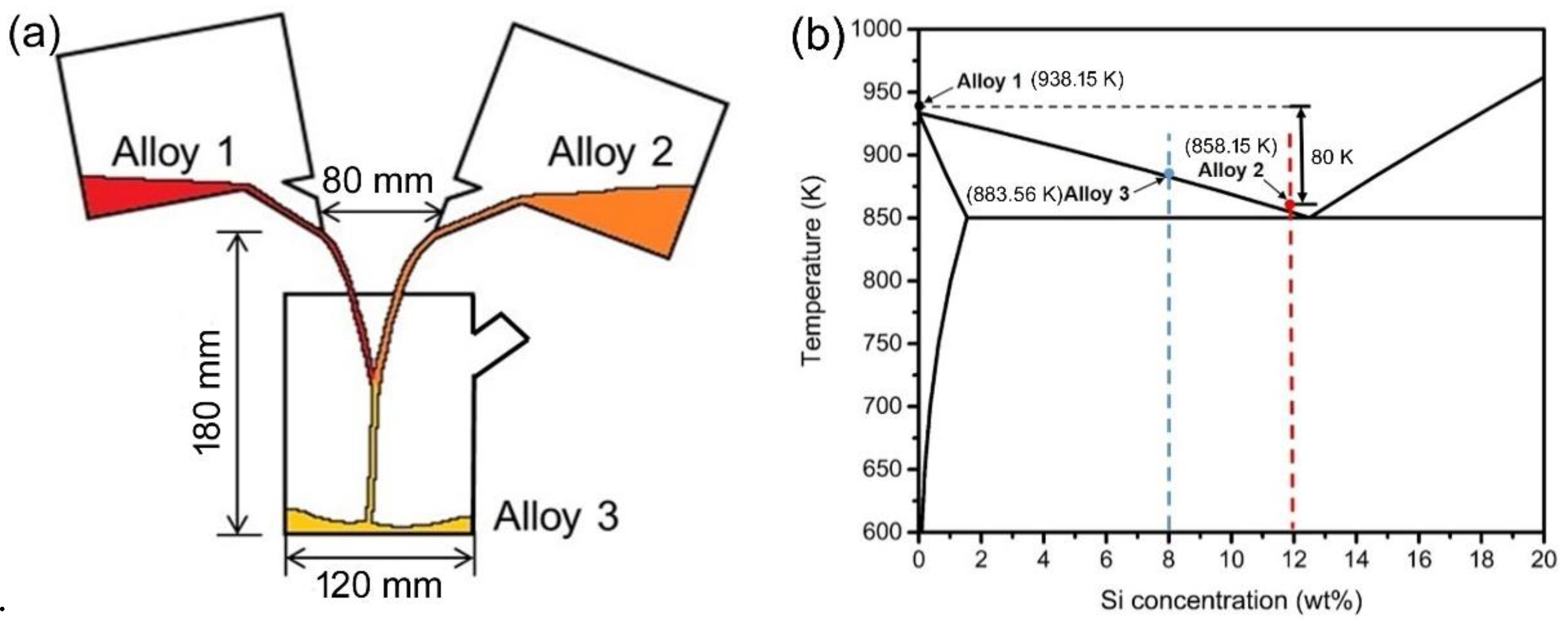
  • It is due to the thermal conductivity being much higher than the solute diffusivity that the melt in the pure Al pockets close to the interface of the pure Al/Al-12Si melts is first rapidly chilled to a supercooling state by the surrounding low-temperature Al-12Si melt, which then causes nuclei to form in this pure Al melt promptly.
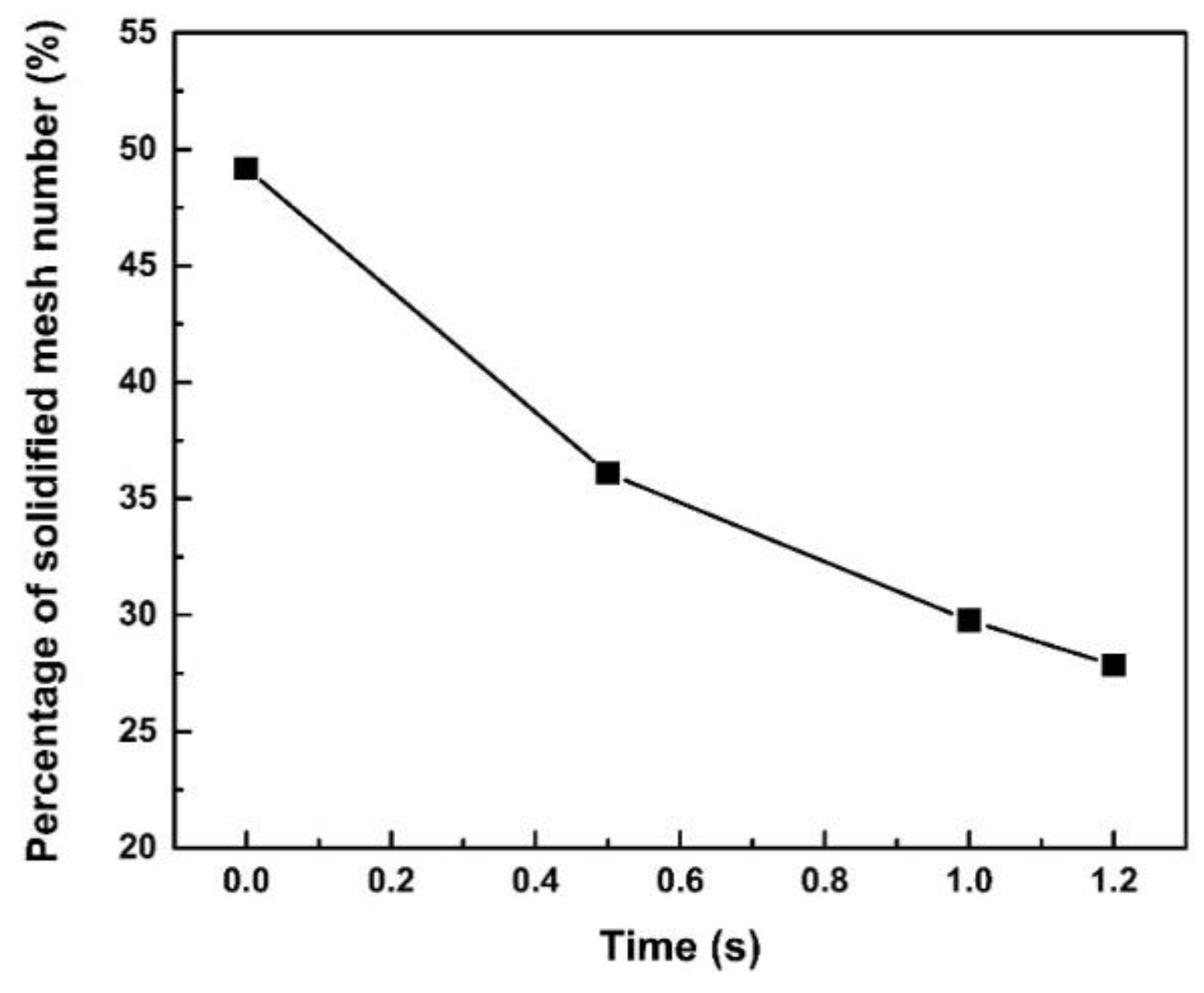
  • Some nuclei remelt, and the others grow only towards the pure Al melt side in a stable solid/liquid interface during standing, increasing the size of nondendritic grains but decreasing their number. However, all the grown nondendritic grains will finally remelt again due to the superheat characteristics of the mixture.
  • The experiment results, such as the change tendencies of the grain morphology, size and number, are consistent with those from the simulation and calculation, implying that the employed simulation and calculation and the achieved results are reasonable and reliable. The mixture should be poured within 10 s after mixing in order to avoid the obvious remelting of grains.

Author Contributions

T.C. designed the experimental program; Y.L. performed the experiments and analyzed the experiment results under the guidance of T.C.; T.C. and Y.L. wrote the paper. All authors have read and agreed to the published version of the manuscript.

Funding

This work was supported by the National Key Research and Development Program of China (grant number 2018YFB2001800).

Data Availability Statement

Not applicable.

Acknowledgments

All individuals included in this section have consented to the acknowledgement.

Conflicts of Interest

The authors declare no conflict of interest.

References

  1. Apelian, D.; Makhlouf, M.M.; Saha, D. CDS Method for Casting Aluminium-Based Wrought Alloy Compositions: Theoretical Framework. Mater. Sci. Forum. 2006, 519–521, 1771–1776. [Google Scholar] [CrossRef]
  2. Kumar, G.; Hegde, S.; Prabhu, K.N. Heat transfer and solidification behaviour of modified A357 alloy. J. Mater. Process. Technol. 2007, 182, 152–156. [Google Scholar] [CrossRef]
  3. Suh, D.W.; Lee, S.Y.; Lee, K.H.; Lim, S.K.; Oh, K.H. Microstructural evolution of Al–Zn–Mg–Cu–(Sc) alloy during hot extrusion and heat treatments. J. Mater. Process. Technol. 2004, 1330, 155–156. [Google Scholar] [CrossRef]
  4. Saha, D.; Shankar, S.; Apelian, D.; Makhlouf, M.M. Casting of aluminum-based wrought alloys using controlled diffusion solidification. Met. Mater. Trans. A 2004, 35, 2174. [Google Scholar] [CrossRef]
  5. Ghiaasiaan, R.; Amirkhiz, B.S.; Shankar, S. Quantitative metallography of precipitating and secondary phases after strengthening treatment of net shaped casting of Al-Zn-Mg-Cu (7000) alloys. Mater. Sci. Eng. A 2017, 698, 206. [Google Scholar] [CrossRef]
  6. Chen, T.J.; Yang, X.K.; Xue, H.; Bi, G.L.; Zhang, X.Z.; Guan, R.G. Mixing process and nucleation of an Al-Si alloy during controlled diffusion solidification with simultaneous mixing and effect of mixing rate. J. Mater. Sci. 2022, 57, 3018. [Google Scholar] [CrossRef]
  7. Haga, T.; Nakamura, R.; Tago, R.; Watari, H. Effects of casting factors of cooling slope on semisolid condition. Trans. Nonferrous Met. Soc. China 2010, 20, 968. [Google Scholar] [CrossRef]
  8. Zhang, Z.-X.; Chen, T.-J.; Liu, K.; Xue, H.; Qi, J.-C.; Bi, G.-L.; Ma, Y. Efficient fabrication of semisolid nondendritic Al alloy slurry with high quality. China Foundry 2022, 19, 117–130. [Google Scholar] [CrossRef]
  9. Birol, Y. A357 thixoforming feedstock produced by cooling slope casting. J. Mater. Process. Technol. 2007, 186, 94–101. [Google Scholar] [CrossRef]
  10. Yang, X.; Li, Y.-D.; Luo, X.-M.; Zhou, H.-W.; Cai, Q.-Y.; Li, M.; Ma, Y. Microstructural evaluation and mechanical properties of 7075 aluminum alloy prepared by controlled diffusion solidification. China Foundry 2019, 16, 238–247. [Google Scholar] [CrossRef]
  11. Ghiaasiaan, R.; Zeng, X.; Shankar, S. Controlled Diffusion Solidification (CDS) of Al-Zn-Mg-Cu (7050): Microstructure, heat treatment and mechanical properties. Mater. Sci. Eng. A 2014, 594, 260–277. [Google Scholar] [CrossRef]
  12. Cini, E.; Vinet, B.; Desré, P.J. A thermodynamic approach to homogeneous nucleation via fluctuations of concentration in binary liquid alloys. Philos. Mag. A 2009, 80, 955–966. [Google Scholar] [CrossRef]
  13. Ghiaasiaan, R.; Shankar, S. Microstructure, Intermetallic Phases, and Fractography of the Cast Al-5.8Zn-2.2Mg-2.5Cu Alloy by Controlled Diffusion Solidification. Met. Mater. Trans. A 2020, 51, 4711–4726. [Google Scholar] [CrossRef]
  14. Khalaf, A.A. Controlled Diffusion Solidification: Process Mechanism and Parameter Study. Ph.D. Thesis, McMaster University, Hamilton, ON, Canada, 2010. [Google Scholar]
  15. Birsan, G.; Ashtari, P.; Shankar, S. Valid mould and process design to cast tensile and fatigue test bars in tilt pour casting process. Int. J. Cast Met. Res. 2013, 24, 284–378. [Google Scholar] [CrossRef]
  16. Pourgharibshahi, M.; Saghafian, H.; Divandari, M.; Timelli, G. Controlled Diffusion Solidification Pathway of an AA 7xxx Series Aluminum Alloy. Met. Mater. Trans. A 2018, 50, 326–335. [Google Scholar] [CrossRef]
  17. Khalaf, A.A.; Ashtari, P.; Shankar, S. Formation of Nondendritic Primary Aluminum Phase in Hypoeutectic Alloys in Controlled Diffusion Solidification (CDS): A Hypothesis. Met. Mater. Trans. B 2009, 40, 843–849. [Google Scholar] [CrossRef]
  18. Khalaf, A.A.; Shankar, S. Mechanism of Anomalous Grain Formation during Controlled Diffusion Solidification. JOM 2020, 72, 3733–3743. [Google Scholar] [CrossRef]
  19. Khalaf, A.A.; Shankar, S. Effect of mixing rate on the morphology of primary Al phase in the controlled diffusion solidification (CDS) process. J. Mater. Sci. 2012, 47, 8153–8166. [Google Scholar] [CrossRef]
  20. Ghiaasiaan, R. Controlled Diffusion Solidification Process (CDS) of Al-7xxx Wrought Alloys: Heat Treatments, Microstructures and Mechanical Properties. Ph.D. Thesis, McMaster University, Hamilton, ON, Canada, 2015. [Google Scholar]
  21. Li, Y.D.; Zang, X.L.; Ma, Y.; Apelian, D.; Zhou, H.W. Effect of mixing rate and temperature on primary Si phase of hypereutectic Al-20Si alloy during controlled diffusion solidification (CDS) process. China Foundry 2015, 12, 173. [Google Scholar]
  22. Khalaf, A.A. Mechanism of controlled diffusion solidification: Mixing, nucleation and growth. Acta Mater. 2016, 103, 301–310. [Google Scholar] [CrossRef]
  23. Kund, N.K.; Dutta, P. Numerical simulation of solidification of liquid aluminum alloy flowing on cooling slope. Trans. Indian Inst. Met. 2012, 20, s898–s905. [Google Scholar] [CrossRef]
  24. Ji, S.; Fan, Z. Solidification Behavior of Sn-15 Wt Pct Pb Alloy under a High Shear Rate and High Intensity of Turbulence during Semisolid Processing. Metall. Mater. Tran. A Phys. Metall. Mater. Sci. 2002, 33A, 3511–3520. [Google Scholar] [CrossRef]
  25. Gumulya, M.; Utikar, R.; Evans, G.; Joshi, J.; Pareek, V. Interaction of bubbles rising inline in quiescent liquid. Chem. Eng. Sci. 2017, 166, 1–10. [Google Scholar] [CrossRef]
  26. Khalaf, A.A. Microstructure evolution of Al-Si hypoeutectic alloys prepared by controlled diffusion solidification. Int. J. Adv. Manuf. Technol. 2022, 120, 5003–5014. [Google Scholar] [CrossRef]
  27. Khalaf, A.A.; Shankar, S. Favorable Environment for a Nondendritic Morphology in Controlled Diffusion Solidification. Metall. Mater. Trans. A 2011, 42, 2456–2465. [Google Scholar] [CrossRef]
  28. Das, A.; Fan, Z. Morphological development of solidification structures under forced fluid flow: Experimental observation. Mater. Sci. Technol. 2003, 19, 573–580. [Google Scholar] [CrossRef]
  29. Hariharan, A.; Lu, L.; Risse, J.; Kostka, A.; Gault, B.; Jägle, E.A.; Raabe, D. Misorientation-dependent solute enrichment at interfaces and its contribution to defect formation mechanisms during laser additive manufacturing of superalloys. Phys. Rev. Mater. 2019, 3, 123602. [Google Scholar] [CrossRef]
  30. Kontis, P.; Chauvet, E.; Peng, Z.; He, J.; da Silva, A.K.; Raabe, D.; Tassin, C.; Blandin, J.-J.; Abed, S.; Dendievel, R.; et al. Atomic-scale grain boundary engineering to overcome hot-cracking in additively-manufactured superalloys. Acta Mater. 2019, 177, 209–221. [Google Scholar] [CrossRef]
Figure 1. (a) Dimensions of the used model, and (b) temperatures and compositions of Alloy 1, Alloy 2 and Alloy 3 marked in Al–Si binary phase diagram.
Metals 13 00733 g001
Figure 2. Schematic diagram of the model for revealing the interface conditions of pure Al/Al-12 melts.
Metals 13 00733 g002
Figure 3. Density distribution fields along the longitudinal section of the mixture when stood for (a) 0 s, (b) 0.5 s, (c) 1.0 s and (d) 1.2 s.
Metals 13 00733 g003
Figure 4. Concentration fields along the cross-section at half of the height of the mixture when stood for (a) 0 s, (b) 0.5 s, (c) 1.0 s and (d) 1.2 s.
Metals 13 00733 g004
Figure 5. Temperature fields along the cross-section at half of the height of the mixture when stood for (a) 0 s, (b) 0.5 s, (c) 1.0 s and (d) 1.2 s.
Metals 13 00733 g005
Figure 6. Flow fields along the cross-section at half of the height of the mixture when stood for (a) 0 s, (b) 0.5 s, (c) 1.0 s and (d) 1.2 s.
Metals 13 00733 g006
Figure 7. Magnified images of the regions marked in Figure 4c,d and Figure 5c,d. Inserts in (a)–(d) are the further magnified images of the corresponding regions marked.
Metals 13 00733 g007
Figure 8. Variations in temperature and Si concentration at the center region of the mixture due to standing time.
Metals 13 00733 g008
Figure 9. Schematics of solidified meshes along the cross-section at half of the height of the mixture when stood for (a) 0 s, (b) 0.5 s, (c) 1.0 s and (d) 1.2 s.
Metals 13 00733 g009
Figure 10. Variation in the percentage of solidified mesh number with standing time.
Metals 13 00733 g010
Figure 11. Interface conditions between pure Al and Si-12Si melts when standing for (a) 10−8 s and (b) different lengths of time ranging from 10−8 s to 7 × 10⁻⁶ s; (c) variation in grain size due to standing time; and (d) schematic of grain growth.
Metals 13 00733 g011
Figure 12. Microstructures of the water-quenched mixture after standing for (a) 0 s, (b) 5 s, (c) 10 s, (d) 30 s, (e) 60 s and (f) 10 min.
Metals 13 00733 g012
Figure 13. Variations in average size, shape factor, number and fractions of nondendritic primary Al grains due to standing time.
Metals 13 00733 g013
Disclaimer/Publisher’s Note: The statements, opinions and data contained in all publications are solely those of the individual author(s) and contributor(s) and not of MDPI and/or the editor(s). MDPI and/or the editor(s) disclaim responsibility for any injury to people or property resulting from any ideas, methods, instructions or products referred to in the content.

