Abstract
In this paper, the influence mechanism of tempering temperature on the microstructure and mechanical properties of 35CrMo steel used in the hammerhead of piston-type impact pile hammer is systematically analyzed. The microstructure was characterized by scanning and transmission electron microscope, X-ray diffraction, and electron backscattering diffraction, and the mechanical properties were tested by the uniaxial tensile test and Charpy V-notch impact test. The results show that after tempering at 580–680 °C, the microstructure of 35CrMo is tempered sorbite. With the increase in tempering temperature, the α phase in the matrix gradually recovers, the dislocation density decreases, the low-angle grain boundaries gradually change to the high-angle grain boundaries, and the carbides gradually change from long rod-shaped network continuous distribution to spherical uniform dispersion distribution, but all of them are M3C. Meanwhile, with the increase in tempering temperature, the strength decreases and the toughness increases, which is mainly affected by dislocation density and matrix supersaturation. Furthermore, 35CrMo enters the two-phase zone after tempering at 710–740 °C, and its microstructure is lamellar martensite, with carbide dissolved. At this point, its mechanical properties mainly depend on grain size.
1. Introduction
The piston-type impact pile hammer driven by hydraulic pressure is widely used because of its advantages of high-impact energy efficiency, convenient operation, and environmental protection, which can meet the strict requirements of piling technology in the fields of building construction, roads and bridges, ports and waterways, etc. [1,2,3]. In this pile hammer system, the piston as the hammerhead will bear a high load and high-frequency pulse impact force. At present, the piston is usually made of medium and low-carbon steel and carburized to meet the requirements of impact conditions on its surface hardness and wear resistance. However, the carburized piston still has some failure forms, such as the cracking of carburized layer, the dent of the impact end face, crack propagation, and slight deformation of the whole body, due to the lack of strength and toughness of its core material [4,5]. Therefore, the mechanical properties of the piston matrix material, such as strength and impact toughness, are the prerequisites for determining the service life of the hydraulic impact pile hammer and the maximum impact force allowed by the impact pile hammer [6]. Notably, 35CrMo alloy steel (the alloy essential composition is 0.35C0.8Mn 0.95Cr 0.2Mo) is a kind of chromium molybdenum medium carbon low alloy steel. Because of its low price, excellent comprehensive mechanical properties, and good processability, such as hardenability, creep resistance, quenching deformability, and machinability, it is widely used to manufacture all kinds of important parts bearing impact, bending and torsion, high load, and important structural parts under high load [7,8,9]. Therefore, 35CrMo steel is a potential hammer material for piston impact pile hammers.
Quenching and tempering are one of the important methods for improving material properties. The formulation of tempering technology affects microstructure evolution and determines the final mechanical properties [10]. The microstructure evolution of Cr-Mo steel during tempering has attracted extensive attention because of the enhancement of its thermal strength and creep resistance by Cr and Mo, and tempering temperature as the main parameter of the steel tempering process has become an important variable in various research [11,12]. According to Luo et al., the tempering temperature can control the decomposition degree of martensite/austenite islands (M-A) in the microstructure of low alloy Cr-Mo steel and then optimize its impact toughness [13]. Furthermore, the test results of mechanical properties of steel 30CrNi2MoV, 40CrNiMo, 40CrNi2MoA, and NiCrMoV after the tempering show that the strength decreases and the plasticity increases with the increase in tempering temperature [14]. Lee and Su pointed out that when 40CrNiMo steel was tempered at its lower critical temperature (AC1), the change of mechanical properties was basically consistent with the above rules, but when the tempering temperature was 300 °C, martensite tempering embrittlement occurred, and there were many layered carbides precipitated by retained austenite in the microstructure [15]. Zhao et al. [16] also found a discontinuous change in mechanical properties. Meanwhile, most studies have pointed out that the evolution of the second phase (such as precipitated carbide) accompanying the tempering process will affect the final mechanical properties of martensitic steel. Jiang et al. indicated that the final mechanical properties of 2.25Cr1Mo0.25V steel after different tempering processes depend not only on the decomposition of martensite austenite (M-A) but also on the precipitation of carbides [17]. In George Kraus’s view, the dispersion distribution of carbide in steel is beneficial to improve its strength and toughness, but the increase in tempering temperature will lead to the increase in martensite lath width and coarsening of carbide, thus reducing its strength. The existence of the second phase, such as transition carbide, cementing, and retained austenite, will make the changing trend of mechanical properties discontinuous with the increase in tempering temperatures, such as the deterioration of toughness caused by martensite embrittlement [18]. By comparing and analyzing the type, shape, size, and distribution characteristics of the second phase in G18CrMo2-6 steel at different tempering temperatures, Li et al. believed that the second-phase structure is related to the critical fracture stress that induces crack initiation, and it is the key factor that affects the impact properties of G18CrMo2-6 steel, especially in the ductile-brittle transition temperature range, and its fracture depends entirely on the size of the initial crack initiated by the second-phase [19,20]. Chen pointed out that the coarsening of carbide will lead to the deterioration of the impact toughness of 42CrMo steel during high-temperature tempering [21]. Therefore, it is of practical significance to pay attention to the relationship between the microstructure evolution (especially the characteristics of the second phase) and the final mechanical properties of Cr-Mo steel at different tempering temperatures for obtaining the optimal tempering process.
35CrMo steel is a kind of low alloy steel which is widely used under various heavy-duty conditions. It is of great significance to study the effects of different heat treatment processes on its mechanical properties for obtaining the best process parameters under specific conditions. Li paid attention to the influence of pretreatment processes such as quenching and normalizing at different temperatures on the hardness and tensile strength of 35CrMo steel. It was found that the mechanical properties of quenched 35CrMo steel are better than that of normalized steel, and the initial microstructure is different due to different pretreatment processes, which would greatly affect the final mechanical properties of the sample [22]. Praveen Singh studied the influence of different quenching media on the microstructure evolution, mechanical properties, and wear resistance of 35CrMo steel and, finally, found that the volume fraction of martensite structure in 35CrMo steel would increase with the increase in cooling rate determined by quenching media, and the formation of martensite was beneficial to the improvement of strength, hardness and wear resistance, but toughness would decrease [23]. In addition, more research work on 35CrMo steel is focused on process experiments or surface treatment and micro-pitting corrosion behavior [8,24,25,26], but there is still a lack of systematic research on microstructure evolution, dislocation substructure level and their relationship with mechanical properties during tempering, especially in the relatively high tempering temperature range. In this paper, 35CrMo steel will be quenched and tempered at high temperatures, and the influence mechanism of tempering temperature on its microstructure, distribution, and morphology of the second phase and substructure level will be analyzed, which will provide some theoretical guidance for the actual production and preparation process of the hammerhead materials of a hydraulic hammer.
2. Experimental Section
2.1. Raw Material and Heat Treatment
The raw material used in the experiment is a forged round bar 35CrMo steel sample with a diameter of 150 mm and a length of 100 mm, and its original structure was ferrite and spheroidized carbides. Firstly, the chemical composition was determined by a vertical full spectrum spark direct reading spectrometer. The measured results are shown in Table 1. Comparing the listed AISI standards, it can be seen that the chemical composition of the materials used in the experiment meets the requirements of 35CrMo in the AISI standards.

Table 1.
Main chemical composition of 35CrMo Steel in AISI standard and this work (wt.%).
2.2. Heat Treatment
The forged bar was cut into 70 mm × 48 mm × 12 mm specimens, homogenized at 1050 °C for 20 h, and then heated from room temperature for 3 h to 860 °C and insulated for 2 h. After being removed, the samples were cooled in oil to room temperature. Then, the above oil-quenched samples were heated to 580, 610, 640, 680, 710, and 740 °C for 2 h, and then kept for 2 h. The samples were taken out and cooled to room temperature in air, and the detailed heat treatment process curve was shown in Figure 1.
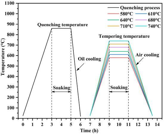
Figure 1.
Schematic map of heat treatment for 35CrMo steel.
2.3. Microstructural Observation
The metallographic structures of quenched and tempered samples at six different temperatures were analyzed. After grinding, polishing, and etching with 4% nitric acid alcohol solution, the metallographic structures under different heat treatment conditions were observed with an OLYMPUS GX53 optical microscope (OM, Olympus Corporation, Tokyo, Japan) and Zeiss GeminiSEM 500 field emission scanning electron microscope (SEM, Zessi Company, Oberkochen, Germany). X-ray diffraction (XRD) was accomplished by SmartLab SE03030502 XRD scans equipped with Ni-filtered Cu Kα radiation (Rigaku Corporation, Tokyo, Japan), the diffraction angle range is set to 40° to 102°, and the scanning accuracy is 2°/min. Electron back-scattered diffusion (EBSD) (step size of measurement is 0.75 μm) was used to analyze the texture. The EBSD samples were electrolyte polished with 5 vol.% perchloric acid alcohol solution, the polishing voltage was 12 V, and the polishing time was 10 ~ 15 s. The transmission electron microscope (TEM) samples were prepared by electrolytic corrosion method. The wafer samples with diameter of 3 mm were mechanically thinned to a thickness of 50 μm at different tempering temperatures and thinned using Tenupol electrolytic double spraying device. The electrolyte used was 5 vol. % perchloric acid alcohol solution, the electrolytic double spray voltage was 20 V, and the electrolytic temperature was −25 °C~−20 °C. The thin area in the transmission sample was selected, and the microstructure was observed by JEM 2100F transmission electron microscope (JEOL Ltd., Tokyo, Japan), and the working voltage was 200 kV.
2.4. Mechanical Properties
The tempered samples at different temperatures were processed into three V-notched impact specimens with dimensions of 10 mm × 10 mm × 55 mm according to ASTM E23-02-standard test methods for notched bar impact testing of metallic materials. Then, the room temperature Charpy impact test was carried out on the above-mentioned specimens by JB-30 B pendulum impact tester. The impact properties at different tempering temperatures are taken from the average values of the results of three specimens. After ultrasonic cleaning, the impact fracture of the sample was observed by means of scanning electron microscope (SEM) and was analyzed by means of energy dispersive spectroscopy (EDS). The Vickers hardness was tested with a load of 500 gf and a dwell time of 10 s on surface of the polished sample. Tensile specimens at different tempering temperatures were prepared by spark cutting machine, and the gauge distance was 10 mm × 2 mm. The uniaxial tensile test of the specimens at room temperature was carried out by Z 250 tensile testing machine, and the tensile strain rate was 1 × 10³ s−1. At least three specimens were tested at each tempering temperature. In addition, it should be noted that no extensometer is added during the tensile test, so the calculation of elongation requires additional measurement; that is, after the three tensile samples at tempering temperature in each group are pulled off, the broken parts are carefully butted together at the broken parts to ensure that their axes are in the same straight line. At this time, vernier calipers are used to measure the gauge distance after the samples are broken. If it is stipulated that the gauge distance measured at this time is L1 and the gauge distance measured before the fracture is L0, the calculation formula of elongation is as follows:
Similarly, the final elongation of the sample is obtained from the average of three samples at each tempering temperature.
3. Results
3.1. Microstructure and Mechanical Properties after Oil Quenching
The microstructure of 35CrMo steel after oil quenching at 860 °C for 2 h is shown in Figure 2, which is a typical lamellar martensite structure. At the same time, a certain amount of bainite structure can be observed due to the influence of the cooling rate during oil quenching [23]. Notably, 35CrMo steel belongs to medium carbon steel. In the process of austenite-martensite transformation, the mismatch between the new and old phases is larger than that of low-carbon steel, and the corresponding strain energy will be larger. Based on the influence of strain energy on the morphology of martensite, the morphology of martensite will exist in strips at this time [27]. At this time, the tensile strength σb and yield strength σs of 35CrMo steel are 1687 MPa and 1276 MPa, respectively, and the impact energy of 35CrMo steel is only 9.82 J, and its hardness is 532.1 ± 7.2 HV.
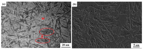
Figure 2.
OM (a) and SEM (b) images of 35CrMo steel after oil quenching.
3.2. Microstructure Evolution
The SEM images of the microstructure of 35CrMo steel tempered at different temperatures are shown in Figure 3. It can be seen that after tempering at 580 °C, 610 °C, 640 °C and 680 °C, the microstructure is tempered sorbite, but the morphology, size, and distribution of precipitates and the morphology of matrix structure are obviously different. The samples tempered at low temperatures (580 °C, 610 °C) have incomplete recovery of α phase in the alloy, and the matrix structure still retains some lath martensite morphology. Since the rich C atoms in the martensite obtained after quenching will preferentially precipitate at the interface of martensite lath during tempering, at this tempering temperature, the cementite precipitated by them is mainly in the form of a plate or strip with a relatively large aspect ratio, as shown in Figure 3a,b. According to Figure 3c, as the tempering temperature increases, most of the needle-like carbides are retained, but their aspect ratio decreases significantly, and some carbides begin to aggregate and gradually spheroidize. The cementite continues to aggregate and grow with the tempering temperature further increasing to 680 °C (Figure 3d), and the cementite is obviously spheroidized, the number of cementing decreases greatly, and the cementite is distributed in granular form on the matrix structure. When the tempering temperature reaches 710 °C, the carbide which had gathered and spheroidized on the matrix structure has dissolved and nearly disappeared, and the martensite structure has gradually lathed, which indicates that the tempering temperature has reached the critical austenitizing temperature of the experimental steel (Figure 3e). This conclusion is more fully proved after tempering at 740 °C, as shown in Figure 3f, the carbide has completely disappeared, and the microstructure has completely changed into lath martensite.
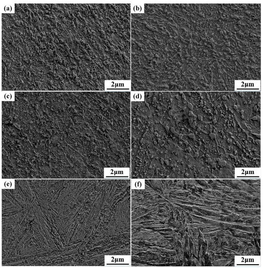
Figure 3.
SEM images of the microstructure of 35CrMo steel after tempering at different temperatures: (a) 580 °C, (b) 610 °C, (c) 640 °C, (d) 680 °C, 710 °C, and (f) 740 °C.
In the TEM image of 35CrMo sample steel tempered at 610 °C shown in Figure 4a, it can be seen that the precipitated carbide has a relatively large aspect ratio and a dense distribution, and it can be identified as M3C carbide by the selected area electron diffraction (SAED). Meanwhile, there are a large number of dislocation cells in the matrix structure, as shown in Figure 4b. The distribution density of M3C carbide in the steel tempered at 680 °C decreased significantly, and the spheroidization is serious. However, the spheroidized carbide is apparently segregated at the grain boundary. We can also see that the grain size of the matrix is obviously larger than that after tempering at 610 °C, which indicates that the martensite grain coarsens obviously with the increase in tempering temperature (Figure 4c). When tempered at 740 °C, the carbide basically dissolves, and the existence of carbide can hardly be seen in its TEM image (Figure 4d), which proves once again that the tempering temperature has entered the sub-temperature quenching zone of the sample steel.
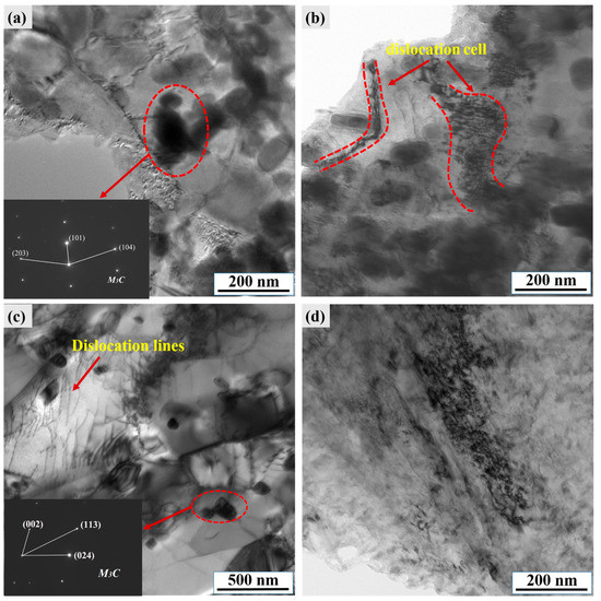
Figure 4.
The Bright field TEM images of 35CrMo steel after tempering at different temperatures (a) and (b) 610 °C, (c) 680 °C, and (d) 740 °C.
Figure 5 shows the Kernel Average Misorientation (KAM) map of the samples tempered at 610 °C, 680 °C, and 740 °C. KAM reflects the homogenization degree of plastic deformation in the test area, which can directly judge the stress distribution law of materials [28]. With the tempering temperature rising from 610 °C to 680 °C, there are more areas with low KAM value, and the distribution is more uniform, which indicates that in this area, the residual stress gradually decreases when the tempering temperature rises but increases again when the tempering temperature rises to 740 °C.
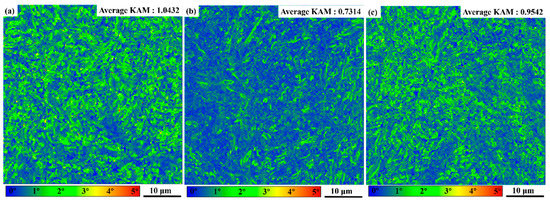
Figure 5.
KAM maps of 35CrMo steel after tempering at different temperatures (a) 610 °C, (b) 680 °C, (c) 740 °C.
After the local orientation difference is known, the geometrically necessary dislocation density can be further calculated by Formula (1).
wherein μ is the step length, b is the length of the Burgers vector, and KAMave represents the average KAM value of the selected area, which can be calculated according to Formula (2).
The KAML,i refers to the local KAM value at point i, and N represents the number of points in the test area.
According to Formulas (2) and (3), the geometric dislocation density is proportional to KAMave [26].
As the tempering temperature increases from 610 °C to 680 °C, the average KAM decreases from 1.0432 to 0.7314, which indicates that the geometric dislocation density gradually decreases as the tempering temperature increases. When the tempering temperature of the sample steel rises to 740 °C, the average KAM value rises again, which means that the dislocation density increases, which also proves that the temperature exceeds the critical temperature of the sample steel, that is, the phase transformation from austenite to martensite occurs again.
Another grain boundary angle that deserves attention during tempering is the grain boundary angle. EBSD analysis shows the grain boundary angle characteristics of test steel tempered at 610 °C, 680 °C, and 740 °C. This set grain boundary angle is Low-Angle Grain Boundaries (LAGBs) when it is less than 10°, and High-Angle Grain Boundaries (HAGBs) when it is greater than 10°. The results of the analysis are shown in Figure 6. It can be seen that when tempered at 610 °C, the proportion of HAGBs is 74.8%, while when tempered at 680 °C, the proportion of HAGBs rises to 79.0%. In this way, martensite grains will be coarsened during tempering, and this coarsening is achieved by eliminating fine grain boundaries. Therefore, martensite grains separated by LAGBs during quenching will gradually recover with tempering, and with the increase in tempering temperature, the proportion of corresponding HAGBs in the unit area will increase. As shown in Figure 6c, the number of LAGBs per unit area increased significantly after the steel specimen was austenitized again and transformed into lath martensite, so the proportion of large angle boundaries decreased to 74.6% after tempering at 740 °C.
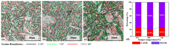
Figure 6.
The low-angle grain boundaries (LAGBs) and high-angle grain boundaries (HAGBs) that are marked in the band contrast images of 35CrMo steel after tempering at different temperatures (a) 610 °C, (b) 680 °C, (c) 740 °C, and percentage stack histogram of LAGBs and HAGBs (d).
3.3. Mechanical Properties
The stress–strain curve of 35CrMo steel tempered at different temperatures at room temperature is shown in Figure 7a. According to the results, the variation law of tensile properties with tempering temperature was summarized, as shown in Figure 7b. In the temperature range of 580 °C to 680 °C, the tensile strength and yield strength decrease as the tempering temperature increases. The tensile strength and yield strength can be maintained at 694 MPa and 546 MPa at 680 °C. As the tempering temperature is higher than 680 °C, the tensile strength and yield strength increase with the increase in tempering temperature, but it is worth noting that when the tempering temperature reaches about 720 °C, the tensile strength and yield strength decrease. The variation of elongation with tempering temperature is just opposite to that of strength, reaching the maximum value (27.5%) at 680 °C and the lowest value (only 9%) at 740 °C. The impact toughness of 35CrMo steel tempered at different temperatures at room temperature is shown in Figure 7c. When tempered at 580–680 °C, the impact toughness gradually increases as the tempering temperature increases. Among them, after tempering at 580 °C and 610 °C, the toughness increases most obviously from the original 92.7 J to 147.5 J, and after tempering at 680 °C, the impact toughness reaches the peak value of 190.0 J, and then the impact toughness decreased with the increase in tempering temperature: after tempering at 710 °C, the impact toughness decreased to 110.0 J, and after tempering at 740 °C, the toughness decreased to the lowest value (90.0 J).
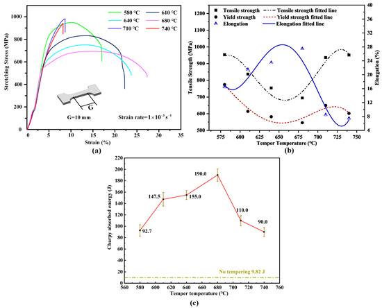
Figure 7.
Mechanical properties of 35CrMo steel at different tempering temperatures. (a) Tensile stress–strain curves, (b) strength and elongation curve, and (c) impact properties curve.
3.4. Impact Fracture Morphology
Figure 8 shows the macro impact fracture morphology of 35CrMo steel tempered at different temperatures at room temperature. After tempering at 580–680 °C, there are shear lip, fiber zone, and radiation zone in the fracture morphology, as shown in Figure 8a–d. With the increase in tempering temperature, the roughness of the fracture surface increases gradually, the proportion of fiber zone and shear lip increases continuously, and the thickness of the shear lip increases significantly. It shows that with the increase in tempering temperature, the frequency of plastic deformation and propagation direction change during crack propagation increases, and the ability to absorb impact energy before fracture increases (that is, the toughness gradually increases). When the tempering temperature continues to increase, the absorbed impact energy decreases rapidly. The macro morphology and roughness of the impact fracture surface obtained after tempering at 710 °C as shown in Figure 8e obviously decrease, and the fracture surface is a standard square, the shear lip and fiber area basically disappear, and the herringbone pattern can be seen on the cross section, which shows a typical brittle fracture. The characteristics of brittle fracture are more obvious after tempering at 740 °C. As shown in Figure 8f, the overall fracture surface is flatter than the impact fracture surface tempered at 680 °C.
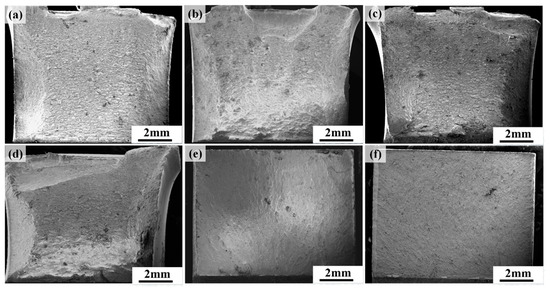
Figure 8.
SEM images of macro fracture morphology of 35CrMo steel tempered at different temperatures after Charpy impact test at room temperature: (a) 580 °C, (b) 610 °C, (c) 640 °C, (d) 680 °C, (e) 710 °C, and (f) 740 °C.
The location near the V-notch in the impact fracture was selected for a high-magnification SEM observation. The results are shown in Figure 9. As shown in Figure 9a, in the micro-morphology of impact fracture at 580 °C, there are a large number of large-area cleavage fracture surfaces, while there are dimples with uneven sizes at the connecting parts of cleavage fracture surfaces, and the second-phase particles with larger particle size can be clearly seen at the bottom of dimples. The area of the cleavage fracture surface decreases obviously after tempering at 610 °C, which indicates that the direction of the crack changes many times in the process of propagation, which will consume some energy. In addition, it can be observed that a large number of tearing edges exist around the cleavage fracture surface, and a large number of small dimples with small size and shallow depth are distributed on the tearing edges, which is the embodiment of toughness improvement (Figure 9b). After the tempering temperature reaches 640 °C, a large number of dimples with equal dimensions are uniformly distributed on the impact fracture surface, which indicates that the ductile fracture is the main one at this time (Figure 9c). Compared with Figure 9d, the size and depth of the dimples on the impact fracture surface after tempering at 680 °C are significantly higher than those of the samples tempered at 640 °C, and the energy absorbed by the corresponding impact fracture increases synchronously. Energy Dispersive Spectroscopy (EDS) analysis of the second-phase inclusions at the bottom of the dimples shows that the inclusions are mainly MnS. Further increasing the tempering temperature to 710 °C, the cleavage plane appears again, and compared with the impact fracture after tempering at 610 °C, the tearing edge is narrower and the number of dimples is smaller (Figure 9e). The cleavage facets in the fracture surface continue to increase and the cleavage steps become more obvious after tempering at 740 °C, even showing a “river-like” pattern in some areas, showing typical cleavage fracture characteristics (Figure 9f).
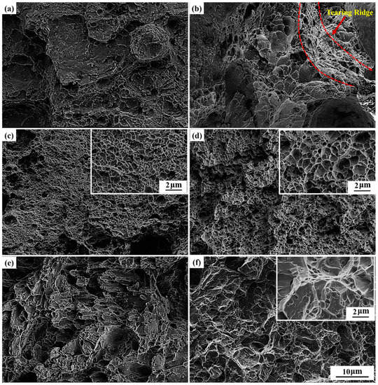
Figure 9.
High-magnification SEM images of fracture morphology of 35CrMo steel tempered at different temperatures: (a) 580 °C, (b) 610 °C, (c) 640 °C, (d) 680 °C, (e) 710 °C, and (d) 740 °C.
4. Discussion
4.1. Influence of Tempering Temperature on Microstructure
Figure 2 shows that the quenched structure of 35 CrMo steel is lath martensite, which can be attributed to the increase in phase expansion rate and the formation of a large amount of strain energy during the phase transformation from austenite to martensite. At the same time, the distortion energy generated by the formation of a new martensite phase by austenite with a high elastic modulus will also increase. Under the combined action of strain energy and distortion energy, the martensite structure of medium carbon steel formed by high-temperature quenching is easy to grow on a plate [29].
As shown by the transition from Figure 5a,b, the high-density dislocations obtained by quenching microstructure gradually decrease with the increase in tempering temperature. This is because during tempering, dislocations slip and rearrange to offset the stress, and some dislocations slip or assimilate into the grain boundaries, resulting in dislocation annihilation. This phenomenon is more obvious with the increase in tempering temperature [30]. The dislocation reduction also means a decrease in residual stress, so the residual stress of 35 CrMo steel decreases with the increase in tempering temperature in the range of 580–680 °C [31]. The tempering mechanism not only reduces dislocations but also eliminates low-angle grain boundaries in the martensite matrix. As shown in the evolution process of Figure 6a,b, the content of LAGBs decreases, while the remaining HAGBs will rearrange, minimizing the area and energy of grain boundaries, and gradually forming equiaxed ferrite grains. With the increase in tempering temperature, this kind of equiaxed crystal becomes more and more obvious, as shown in Figure 3a–d [18,32].
Within the temperature range of 580–680 °C, although the precipitated carbides of 35 CrMo steel at different tempering temperatures are M3C, there are some differences in morphology. In the microstructure after tempering at 580 °C (Figure 3a), the particles of the second phase are very dense, and the main shape is strip-shaped, which indicates that ε-carbide has been basically dissolved in the parent phase at this tempering temperature, and the new and more stable carbide nucleates and grows again in the form of out-of-site transformation. With the increase in tempering temperature, the long rod-shaped second-phase particles are disconnected and discontinuous [12]. Furthermore, after tempering at 640 °C, in order to reduce the surface energy of the precipitated phase, spheroidized carbides begin to appear. With the continuous increase in tempering temperature, the spheroidized carbides grow up, relatively small particles dissolve, and, finally, the microstructure at 680 °C presents as large spheroidal carbides [21,33].
An interesting finding is that the critical austenitizing temperature of the sample steel is lower than the estimated value, and the preset tempering temperature of 710 °C and 740 °C has entered the two-phase zone. At this time, the microstructure of the sample is lath martensite, which is different from the lath martensite after quenching at 860 °C. This difference is caused by the difference in the initial microstructure. At 710 °C, the undissolved fine carbide is still dispersed in the matrix, but at 740 °C, the carbide completely dissolves. With the increase in quenching temperature, the grain size of lath obviously coarsens, mainly because with the increase in quenching temperature, the atomic diffusion ability gradually increases, and the grains grow up by mutual annexation, which shows the increase in grain size [34].
4.2. Influence of Tempering Temperature on Mechanical Properties
When 35CrMo steel is tempered at 580 °C~680 °C, its strength decreases gradually with the increase in tempering temperature, which is closely related to the microstructure evolution of the sample steel during tempering. Firstly, when tempered at 580 °C and 610 °C, the α phase is not completely recovered, and the matrix structure still retains the lamellar martensite morphology to a great extent, which has a certain blocking effect on dislocation movement. With the increase in tempering temperature, this blocking effect gradually decreases with the increase in α phase recovery [17]. At the same time, through the comparative analysis of the dislocation density of the sample tempered at 610 °C and 680 °C (Figure 5a,b), it can be seen that in this tempering temperature range, the dislocation density of the sample steel gradually decreases with the increase in tempering temperature, correspondingly, the number of dislocations that can interact with slip dislocations decrease, resulting in the reduction in the rheological stress required for plastic deformation under the action of external force. That is to say, in this tempering temperature range, the dislocation strengthening effect of 35CrMo steel gradually weakens with the tempering temperature increasing [32,35]. Furthermore, by comparing the lattice constant of alpha-Fe obtained by XRD test analysis (as shown in Figure 10), when 35CrMo steel is tempered at 580 °C–680 °C, the changing trend of lattice constant and strength with tempering temperature are in good agreement. After high-temperature tempering, a large number of carbon atoms and alloy elements exist in the body-centered cubic lattice structure of the matrix structure in the form of gaps, or replacing an iron atom in the lattice, and a large number of iron-based crystals are distorted accordingly [19]. This kind of distortion can interact with the stress field around dislocations, and it can also improve the strength of the material through the obstacle caused by dislocation movement. During the tempering process, the carbon atoms and alloying elements are precipitated successively, and the distortion degree of the iron-based crystal is restored. Because the lattice constant is proportional to the solid solubility of carbon atoms and alloy elements in alpha-Fe, it can be inferred from Figure 10 that the precipitation phenomenon and the degree of distortion recovery will become stronger with the increase in tempering temperature, further indicating that the weakening of the solid solution strengthening effect aggravates the deterioration of strength [32,36]. Furthermore, combining the SEM images and TEM images of the matrix structure of the sample steel tempered at 580 °C–680 °C, and considering that the grain size of the matrix is only related to the nucleation and growth process of austenite during high-temperature quenching, the effect of fine grain strengthening on the strength is not considered. Meanwhile, it can be observed that the grain size of the second phase is larger at different tempering temperatures, which have a certain strengthening effect on the strength of the Orowan mechanism. However, due to the small difference in size, it is considered that the influence of precipitation on the strength of 35CrMo is not significant.
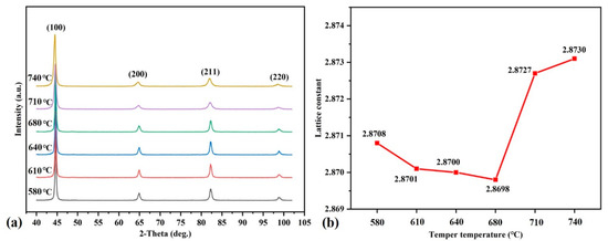
Figure 10.
XRD patterns (a) and the lattice constant of alpha-Fe (b) of 35CrMo steel at different tempering temperatures.
The toughness of 35CrMo steel increases with the increase in tempering temperature when it is tempered at 580 °C–680 °C. It can be said that when 35CrMo is tempered in this temperature range, its dislocation strengthening effect and solution strengthening effect gradually decrease with the increase in tempering temperature (that is to say, the matrix material softens correspondingly). With the increase in the softening degree of the matrix, the plastic deformation zone of 35CrMo which can absorb impact energy in the fracture process increases. As shown in Figure 9a–d, with the increase in tempering temperature, the thickness of the shear lip gradually increases and the crack propagation is relatively slow, which is one of the main reasons for the improvement of impact toughness [37]. Furthermore, the obvious differences in morphology and distribution characteristics of precipitated phases are also worth noting. With the increase in tempering temperature, the carbides in the microstructure shown in Figure 3a–d gradually change from the continuous distribution of a long rod-like network to a uniform spherical dispersion distribution. Firstly, according to Griffith’s fracture theory, the existence of the second phase will limit the size of the crack tip forming zone, thus reducing the initiation work of microcracks per unit area, which is harmful to the fracture toughness of materials. A large number of experiments show that, compared with spherical or near-spherical particles, the long rod-shaped particles with sharp edges have significantly stronger stress concentration, are more prone to microcracks, and are more harmful to toughness. At the same time, the continuous distribution of the second phase in a network is more harmful to the fracture toughness than the uniform dispersion distribution, which makes it easier for cracks to propagate [17,18,20,21,22,32]. Secondly, the disharmony of deformation between precipitates and matrix induces geometrically necessary dislocations. Geometrically necessary dislocations density induced by flake precipitates is one order of magnitude higher than that induced by spherical precipitates, and a large number of dislocations will increase the effective size of microcracks due to their stress concentration, thus damaging the toughness of materials [38]. Therefore, the toughness of 35CrMo will increase with the increase in tempering temperature, which is because the negative influence of the precipitated phase is weakened. In addition, as shown in Figure 6, compared with tempering at 610 °C, the proportion of LAGBs per unit area of 35CrMo tempered at 680 °C decreased from 25.2% to 21%, and the proportion of HAGBs increased correspondingly, indicating that with the increase in tempering temperature, the LAGBs gradually changed to the HAGBs, and the HAGBs change the crack propagation direction, resulting in the bending of crack propagation path and an increase in crack propagation energy. Therefore, compared with the LAGBs, the HAGBs make crack propagation more difficult, thus greatly improving the toughness of materials [32,39].
With the increase in temperature, the grain size of 35CrMo entering the sub-temperature quenching zone increases, resulting in the deterioration of strength and toughness. Even though there are fine carbides in the matrix structure after sub-temperature quenching at 710 °C, its toughness is still better than that of the sample steel after sub-temperature quenching at 740 °C. Therefore, in the sub-temperature quenching zone, the influence of precipitation relative toughness is smaller than that of grain size. In terms of strength, the superposition effect of fine grain strengthening and precipitation strengthening is obviously better than that of solution strengthening.
5. Conclusions
- (1)
- After tempering at 580–680 °C, the microstructure of 35CrMo is tempered sorbite and M3C carbide precipitates. Along with the increase in tempering temperature, the matrix structure α phase gradually recovers, the dislocation density decreases, carbides gradually aggregate and spheroidize, and the solid solubility of carbon atoms and alloy elements in α-Fe decreases, and the proportion of low-angle grain boundaries also decreases.
- (2)
- After 580–680 °C tempering, the strength of 35CrMo decreases, and the toughness increases with the increase in tempering temperature. Within this tempering temperature range, the main factors affecting the strength are the dislocation density of the matrix and the solid solubility of carbon atoms and alloying elements. The matrix softening, dislocation density, and solid solubility also have important effects on the toughness of 35CrMo. In addition, its toughness is closely related to the morphology and distribution of carbides and the proportion of high-angle grain boundary angles.
- (3)
- The Austenitic critical temperature (AC1) of 35CrMo sample steel is between 680 °C and 710 °C, so the grain size increases with the increase in temperature when tempering above this critical temperature, and the grain size is the key factor affecting the mechanical properties of 35CrMo in the sub-temperature quenching zone.
- (4)
- As the tempering temperature increases, the tensile and yield strengths decrease and then increase with increasing tempering temperature, with the tensile and yield strengths remaining at 734 MPa and 586 MPa for specimens tempered at 680 °C. In addition, the tensile and yield strengths decrease with increasing tempering temperatures, and the impact toughness tends to increase and then decrease as the tempering temperature increases, reaching a peak of 190.0 J after tempering at 680 °C and a minimum (90.0 J) after tempering at 740 °C.
Author Contributions
All the authors contributed to the conceptualization and design of the study. The material preparation, data collection, and analysis were performed by Q.R., Z.K., J.W., T.H. and P.X. The first draft of the manuscript was written by Q.R., and all the authors provided inputs for the initial versions of the manuscript. All authors have read and agreed to the published version of the manuscript.
Funding
This work was supported by the National Natural Science Foundation of China (Grant No. U1910212).
Data Availability Statement
Relevant research data can be obtained upon request from the corresponding author.
Conflicts of Interest
The authors declare no conflict of interest.
References
- Guo, Y.; Hu, J.P.; Zhang, L.Y. Finite-element analysis of multi-body contacts for pile driving using a hydraulic pile hammer. Proc. Inst. Mech. Eng. Part C J. Mech. Eng. Sci. 2011, 225, 1153–1161. [Google Scholar] [CrossRef]
- Tuncdemir, H. Impact hammer applications in Istanbul metro tunnels. Tunn. Undergr. Space Technol. 2008, 23, 264–272. [Google Scholar] [CrossRef]
- Hu, J.P.; Li, K.J.; Zhu, H.D. Dynamic Analysis of Hammer Buffer System Using Pseudo-Bond Graph Simulation Method. Adv. Mater. Res. 2014, 908, 335–339. [Google Scholar] [CrossRef]
- Jiang, B.; Liu, Y.; Zhou, L.; Zhang, C.; Chen, L.; Wang, G. Research Status of Microstructure and Properties Control of Steel for Heavy Drill. Cailiao Daobao/Mater. Rev. 2019, 33, 854–861. [Google Scholar]
- Zhenwei, W.; Jianping, W.; Changwen, H.; Jiabing, S.; Baoguo, X.; Xingquan, Z. Cracking failure analysis of steel piston forging die. Eng. Fail. Anal. 2022, 138, 106291. [Google Scholar] [CrossRef]
- Sokolski, M.; Sokolski, P. Strength estimation of the impact zone—A critical area of the tools of the hydraulic hammers. Arch. Civ. Mech. Eng. 2016, 16, 767–776. [Google Scholar] [CrossRef]
- Xiao, Z.-B.; Huang, Y.-C.; Liu, Y. Plastic Deformation Behavior and Processing Maps of 35CrMo Steel. J. Mater. Eng. Perform. 2016, 25, 1219–1227. [Google Scholar] [CrossRef]
- Lv, Y. Influence of laser surface melting on the micropitting performance of 35CrMo structural steel gears. Mater. Sci. Eng. A 2013, 564, 1–7. [Google Scholar] [CrossRef]
- Duan, X.; Yu, H.; Lu, J.; Huang, Z. Temperature Dependence and Formation Mechanism of Surface Decarburization Behavior in 35CrMo Steel. Steel Res. Int. 2019, 90, 1–8. [Google Scholar] [CrossRef]
- Shu, Z.Q.; Yuan, P.B.; Ouyang, Z.Y.; Gong, D.M.; Bai, X.M. Effects of Tempering Temperature on Microstructure and Mechanical Properties of Drill Pipe Steel 26CrMo. Acta Metall. Sin. 2017, 53, 669–676. [Google Scholar]
- Peral, L.B.; Zafra, A.; Belzunce, J.; Rodríguez, C. Effects of hydrogen on the fracture toughness of CrMo and CrMoV steels quenched and tempered at different temperatures. Int. J. Hydrogen Energy 2019, 44, 3953–3965. [Google Scholar] [CrossRef]
- Krauss, G. Deformation and fracture in martensitic carbon steels tempered at low temperatures Verformung und bruch von bei niedrigen temperaturen angelassenen unlegierten stahlen. HTM—Haerterei-Tech. Mitteilungen 2002, 57, 106–115. [Google Scholar]
- Luo, Y.; Peng, J.-M.; Wang, H.-B.; Wu, X.-C. Effect of tempering on microstructure and mechanical properties of a non-quenched bainitic steel. Mater. Sci. Eng. A 2010, 527, 3433–3437. [Google Scholar] [CrossRef]
- Saeglitz, M.; Krauss, G. Deformation, fracture, and mechanical properties of low-temperature-tempered martensite in SAE 43xx steels. Metall. Mater. Transac. A Phys. Metall. Mater. Sci. 1997, 28, 377–387. [Google Scholar] [CrossRef]
- Lee, W.-S.; Su, T.-T. Mechanical properties and microstructural features of AISI 4340 high-strength alloy steel under quenched and tempered conditions. J. Mater. Process. Technol. 1999, 87, 198–206. [Google Scholar] [CrossRef]
- Zhao, Y.-J.; Ren, X.-P.; Hu, Z.-L.; Xiong, Z.-P.; Zeng, J.-M.; Hou, B.-Y. Effect of tempering on microstructure and mechanical properties of 3Mn-Si-Ni martensitic steel. Mater. Sci. Eng. A 2018, 711, 397–404. [Google Scholar] [CrossRef]
- Jiang, Z.H.; Wang, P.; Li, D.Z.; Li, Y.Y. Effects of tempering temperature on the microstructure and me-chanical properties of granular bainite in 2.25Cr-1Mo-0.25V steel. Acta Metall. Sin. 2015, 51, 925–934. [Google Scholar]
- Krauss, G. Tempering of Lath Martensite in Low and Medium Carbon Steels: Assessment and Challenges. Steel Res. Int. 2017, 88, 1700038. [Google Scholar] [CrossRef]
- Li, Z.; Liu, Y.; Zhang, R.; Luo, C.; Qi, H. Study on impact fracture behavior of G18CrMo2-6 steel after tempering. Proc. Inst. Mech. Eng. Part L: J. Mater. Des. Appl. 2021, 235, 2627–2636. [Google Scholar] [CrossRef]
- Li, Z.J.; Xiao, N.M.; Li, D.Z.; Zhang, J.Y.; Luo, Y.J.; Luo, R.X. Influence of microstructure on impact toughness of G18CrMo2-6 steel during tempering. Acta Metall. Sin. 2014, 50, 77–786. [Google Scholar]
- Chen, J.; Mo, W.; Wang, P.; Lu, S. Effects of tempering temperature on the impact toughness of steel 42CrMo. Acta Metall. Sin. 2012, 48, 1186. [Google Scholar] [CrossRef]
- Li, A.M.; Hu, M.J. Influence of Original Structure on Microstructure and Properties of 35CrMo Steel after Zero Time Holding Quenching. Adv. Mater. Res. 2012, 472–475, 978–981. [Google Scholar] [CrossRef]
- Singh, P.; Singh, S. Effect of quenching media on microstructural evolution, mechanical and wear properties of AISI4135 steel. Proc. Inst. Mech. Eng. Part C J. Mech. Eng. Sci. 2021, 235, 5616–5625. [Google Scholar] [CrossRef]
- Li, Z.; Zhou, Y.; Wang, S. Influence of Strain and Stress Triaxiality on the Fracture Behavior of GB 35CrMo Steel during Hot Tensile Testing. Adv. Mater. Sci. Eng. 2018, 2018, 5124524. [Google Scholar] [CrossRef]
- Zhang, J.; Lu, L.; Shiozawa, K.; Zhou, W.; Zhang, W. Effect of nitrocarburizing and post-oxidation on fatigue behavior of 35CrMo alloy steel in very high cycle fatigue regime. Int. J. Fatigue 2011, 33, 880–886. [Google Scholar] [CrossRef]
- Li, S.; Akiyama, E.; Uno, N.; Hirai, K.; Tsuzaki, K.; Zhang, B. Evaluation of delayed fracture property of outdoor-exposed high strength AISI 4135 steels. Corros. Sci. 2010, 52, 3198–3204. [Google Scholar] [CrossRef]
- Liu, Z.-C.; Ji, Y.-P.; Duan, B.-Y.; Ren, H.-P. Substructure and formation mechanism of lath martensite. Cailiao Rechuli Xuebao/Transac. of Mater. Heat Treat. 2011, 32, 56–61. [Google Scholar]
- Yan, Z.; Wang, D.; He, X.; Wang, W.; Zhang, H.; Dong, P.; Li, C.; Li, Y.; Zhou, J.; Liu, Z.; et al. Deformation behaviors and cyclic strength assessment of AZ31B magnesium alloy based on steady ratcheting effect. Mater. Sci. Eng. A 2018, 723, 212–220. [Google Scholar] [CrossRef]
- Ji, Y.P.; Liu, Z.C.; Ren, H.P. Morphology and Formation Mechanism of Martensite in Steels with Different Carbon Content. Adv. Mater. Res. 2011, 201–203, 1612–1618. [Google Scholar] [CrossRef]
- Wen, T.; Hu, X.; Song, Y.; Yan, D.; Rong, L. Effect of tempering temperature on carbide and mechanical properties in a Fe-Cr-Ni-Mo high-strength steel. Jinshu Xuebao/Acta Metall. Sin. 2014, 50, 447–453. [Google Scholar]
- Soleimani, M.; Mirzadeh, H.; Dehghanian, C. Effects of tempering on the mechanical and corrosion properties of dual phase steel. Mater. Today Commun. 2019, 22, 100745. [Google Scholar] [CrossRef]
- Sun, C.; Fu, P.-X.; Liu, H.-W.; Liu, H.-H.; Du, N.-Y. Effect of Tempering Temperature on the Low Temperature Impact Toughness of 42CrMo4-V Steel. Metals 2018, 8, 232. [Google Scholar] [CrossRef]
- Liu, M.; Wang, C.H.; Dai, Y.C.; Li, X.; Cao, G.H.; Russell, A.M.; Liu, Y.H.; Dong, X.M.; Zhang, Z.H. Effect of quenching and tem-pering process on sulfide stress cracking susceptibility in API-5CT-C110 casing steel. Mater. Sci. Eng. A 2017, 688, 378–387. [Google Scholar] [CrossRef]
- Wen, M.; Dong, W.; Pang, H.; Lu, S. Microstructure and Impact Toughness of Welding Heat- Affected Zones of a Fe-Cr-Ni-Mo High Strength Steel. Jinshu Xuebao/Acta Metall. Sin. 2018, 54, 501–511. [Google Scholar]
- Liu, H.; Fu, P.; Liu, H.; Sun, C.; Ma, X.; Li, D. Microstructure evolution and mechanical properties in 718H pre-hardened mold steel during tempering. Mater. Sci. Eng. A 2017, 709, 181–192. [Google Scholar] [CrossRef]
- Hutchinson, B.; Hagström, J.; Karlsson, O.; Lindell, D.; Tornberg, M.; Lindberg, F.; Thuvander, M. Microstructures and hardness of as-quenched martensites (0.1–0.5%C). Acta Mater. 2011, 59, 5845–5858. [Google Scholar] [CrossRef]
- Yan, P.; Liu, Z.; Bao, H.; Weng, Y.; Liu, W. Effect of tempering temperature on the toughness of 9Cr–3W–3Co martensitic heat resistant steel. Mater. Des. 2014, 54, 874–879. [Google Scholar] [CrossRef]
- Yuan, S.P.; Liu, G.; Wang, R.H.; Pu, X.; Zhang, G.J.; Sun, J.; Chen, K.H. Coupling effect of multiple precipitates on the ductile fracture of aged Al–Mg–Si alloys. Scr. Mater. 2007, 57, 865–868. [Google Scholar] [CrossRef]
- Liu, J.; Yu, H.; Zhou, T.; Song, C.; Zhang, K. Effect of double quenching and tempering heat treatment on the microstructure and mechanical properties of a novel 5Cr steel processed by electro-slag casting. Mater. Sci. Eng. A 2014, 619, 212–220. [Google Scholar] [CrossRef]


Disclaimer/Publisher’s Note: The statements, opinions and data contained in all publications are solely those of the individual author(s) and contributor(s) and not of MDPI and/or the editor(s). MDPI and/or the editor(s) disclaim responsibility for any injury to people or property resulting from any ideas, methods, instructions or products referred to in the content. |
© 2023 by the authors. Licensee MDPI, Basel, Switzerland. This article is an open access article distributed under the terms and conditions of the Creative Commons Attribution (CC BY) license (https://creativecommons.org/licenses/by/4.0/).