Article

Iron Diffusion in Electron Beam Melt (EBM) γ-TiAl Based Alloy from the Building Platform: Interface Characterization

by
Mohammad Saleh Kenevisi
1,2,*,
Cristian Ghibaudo
1,2,
Emilio Bassini
1,2,
Daniele Ugues
1,2,
Giulio Marchese
1,2 and
Sara Biamino
1,2
1
Department of Applied Science and Technology (DISAT), Polytechnic University of Turin, Corso Duca degli Abruzzi 24, 10129 Turin, Italy
2
Integrated Additive Manufacturing iAM@PoliTO Center, Polytechnic University of Turin, Corso Castelfidardo 51, 10138 Turin, Italy
*
Author to whom correspondence should be addressed.
Metals 2023, 13(4), 772; https://doi.org/10.3390/met13040772
Submission received: 21 March 2023 / Revised: 5 April 2023 / Accepted: 13 April 2023 / Published: 15 April 2023
(This article belongs to the Section Additive Manufacturing)

Abstract

:
Electron beam melting (EBM) is a promising technique for processing γ-TiAl alloys that are susceptible to cracking. TiAl alloys are usually built on stainless steel platforms to reduce overall costs. The interface between the samples and the platform is generally brittle due to the strong diffusion of elements between the two components, making them easily separable just by applying impulsive bending stress. In this work, Ti-48Al-2Cr-2Nb samples were processed via EBM and separated from the platform without altering the interface layer. The interface was studied in four different conditions (as-built, hot isostatic pressed, and solution annealed at 1320 °C and 1360 °C) by using scanning electron microscopy (SEM), energy dispersive X-ray spectroscopy (EDS), X-ray diffraction (XRD), and hardness measurement. The results revealed that due to the diffusion of elements such as Fe Cr, and Ni, some hard intermetallics and phases were formed close to the interface of the platform and the first deposited layers, which was confirmed by SEM and XRD. According to the results among all diffusing elements, only Fe could diffuse significantly past the interface. More specifically, the diffusion range in the as-built condition was limited to about 350 μm. However, when the sample was heat treated at 1360 °C, Fe amounts of about 0.7 wt.% was still traced at distances as far as 500 μm. Additionally, annealing at higher temperatures led to more homogeneous and relatively higher hardness values within the matrix. According to the results obtained, removing the samples from the building platform with Electro Discharge Machining (EDM) above the contaminated layer before performing any heat treatment is advised to avoid the removal of thick material layers in order to get back to the nominal alloying composition.

1. Introduction

γ-Titanium Aluminides (γ-TiAl) are intermetallic compounds extensively studied in recent years. This interest is due to their remarkable mechanical and thermophysical properties at high temperatures, such as high strength and stiffness, low coefficient of thermal expansion, high thermal conductivity, and high corrosion and oxidation resistance [1,2]. These characteristics make them attractive to the aerospace and automotive industries [3]. TiAl-based alloys have densities ranging between 3.9 and 4.2 g/cm3, about half the densities of Ni-based alloys [4]. So, they have been considered suitable alternatives for high-temperature applications to Ni-based alloys and ceramics, which are deemed to be heavy and brittle, respectively. It is reported that the weight of a low-pressure gas turbine engine can be reduced by 20–30% by using blades made of TiAl alloy [5].
Different alloying elements are added to the binary TiAl system to modify the properties of the alloy. Cr and Nb are among the most widely added elements. Cr is a β stabilizer, and the addition of 1–3% of Cr leads to an increase in the ductility. Niobium, in minor addition, can enhance creep and oxidation resistance, while at higher concentrations of about 5–10%, the high-temperature strength is improved [6,7]. Moreover, small amounts of Fe can be added as the alloying element to increase the fluidity of the alloy during casting; however, this also increases the susceptibility to hot cracking [8,9]. TiAl alloys possess unique microstructures, from lamellar to equiaxed and duplex. As is known, changes in the microstructure (such as grain size, the volume fraction of different phases, and lamellar thickness and spacing) can significantly affect the characteristics of the material. A coarse lamellar microstructure is generally achieved when parts are produced by conventional manufacturing processes. However, modifying the microstructure, such as through grain refining, is quite an expensive process.
Moreover, because of their relatively low ductility and susceptibility to thermal cracking, the application of parts produced by conventional manufacturing techniques is still limited, and they have not been widely used in industry. As a result, there has been an interest in applying new manufacturing processes. Recently, electron beam melting (EBM), as an additive manufacturing (AM) process, has been identified as a promising alternative to the conventional processes of manufacturing TiAl alloys [10]. Freedom in design, buy-to-fly ratio, low impurity pick-up, fine microstructure, and enhanced properties are some of the advantages of the EBM process. However, at the same time, some limitations, such as inconsistencies in properties between different platforms, build size, and surface roughness, are also encountered [11,12,13,14,15,16].
The main focus of previous research in this field has been investigating the effect of processing parameters on mechanical properties. For example, research by Cormier et al. [17] is one of the earliest works in processing TiAl with EBM, where a remarkable aluminum loss is reported. Later, further research was done to optimize the processing parameters to reduce the Al loss [18,19,20]. The process-property relationship has been clearly investigated in the literature [10,21,22,23,24]; however, there is still interest in studying how low concentrations of different elements can influence the resulting microstructure.
It is known that the solubility of an element depends on its diffusion behavior, and therefore, different solutes exhibit different diffusion properties. In high-temperature applications, both self- and solute-diffusion play an essential role in the material characteristics. Regarding γ-TiAl, Ti self-diffusion [25], and Cr and Nb [26] solute-diffusion have already been studied, and it is claimed that the diffusion mechanisms are based on and controlled by the sublattices, anti-sites, and anti-structure bridge mechanisms [27,28].
Unlike most intermetallic compounds, Ti self-diffusion in the γ-TiAl system exhibits curvature in the Arrhenius diagram, where the diffusion rate is plotted at different temperatures. This difference is because different mechanisms dominate diffusivity at high and low temperatures [25]. Divinski et al. [29] showed that at relatively high temperatures, Ti diffusion is a non-linear function of temperature. Though at temperatures lower than 1470 K, the diffusion behavior displays an Arrhenius character. The diffusion rate is shown in Equation (1) and can be described as:
D T i = a × 10 6 × exp b k J . m o l 1 R T m 2 s 1
where a and b are constants (slightly affected by the chemical composition), T is the temperature, and R is the gas constant. The diffusion coefficient generally ranges from about 2 × 10⁻¹⁸ to 10−12 m2 s−1 when the temperature increases from 1150 K to 1726 K [29]. It is also claimed that, unlike Ti self-diffusion, Nb shows a linear Arrhenius temperature dependency, and it usually has a lower diffusion coefficient in the range from 7 × 10⁻²⁰ to 9 × 10⁻¹⁵ m2 s−1 [26]. Regarding Fe, it is reported by Przeorski et al. [28] that the diffusion of Fe in γ-TiAl is characterized by two different stages; a straight Arrhenius character for temperatures up to 1450 K, followed by a non-linear Arrhenius curve at higher temperatures. Based on what has already been considered, it can be stated that understanding the thermal stability of TiAl-based alloys and the diffusion processes is critical.
In powder bed fusion additive manufacturing processes, it is favorable to use a baseplate with a chemical composition similar to or close to that of the material being deposited to avoid composition changes in the manufactured parts. However, using a baseplate with the same chemical composition may not always be possible or cost-effective. For example, using baseplates made of stainless steel (SS) as the platform for depositing TiAl by the EBM process has some benefits. Regarding the cost, stainless steel plates are cheaper than the other plates that can be used for this material. Furthermore, concerning time, removing samples from the SS platform is much easier. They can be removed by applying a very low bending load due to the brittleness of the sample/baseplate interface. Therefore, no special post-processing technique, such as electro-discharge machining (EDM), is required. However, at the same time, the diffusion of some elements, such as Fe, in the first deposited layers should be noted. As a result, it is of great importance to study Fe diffusion and investigate its effect on the microstructure and properties of the parts.
This study aims to better understand the microstructural evolution of Ti-48Al-2Cr-2Nb alloy during the EBM and HIP processes in the presence of small amounts of Fe diffused from the baseplate into the first deposited layers. This study is performed by characterizing the as-built and heat-treated samples.

2. Materials and Methods

In this work, Ti48Al2Cr2Nb gas-atomized pre-alloyed powder was used to fabricate the samples. The powder was supplied by ATI Co. with D10 = 60.4 μm, D90 = 156 μm, and a mean diameter of 98 μm. Figure 1 illustrates the particle size distribution of the powder, and the chemical composition of the powder is provided in Table 1.
Cylindrical samples (ϕ 16 mm and 100 mm high) were built by an A2X Arcam EBM (GE Additive) machine on a stainless steel grade 316 plate. The manufacturing process parameters are given in a previous work from our research group [30].
The samples were detached from the platform by applying a bending force by hand, and some were post-processed by a HIP treatment. For the HIP process, the samples were soaked at 1260 °C for 4 h at 170 Mpa in Quintus QIH 15 L post-processing solution to eliminate flaws inherited from the printing stage. Additionally, solution annealing was applied to the HIPed samples. The process was done at two different temperatures: 1320 °C and 1360 °C. For each procedure, the samples were kept at the solutioning temperature for 180 min, followed by gas quenching aiming for a cooling rate close to 170 °C/min in the temperature range between the annealing temperature and 400 °C.
As-built, HIPed, and solution-annealed samples were cut parallel to the building direction to study the microstructure at different locations. For this purpose, and prior to the microstructural investigations, the samples were polished with different SiC papers and 1 μm diamond suspension. The final surface finishing was obtained with colloidal silica. Samples were observed in the as-polished condition. SEM micrographs were then taken using a Zeiss EVO 15 electron microscope equipped with an Ultim Max EDS detector by Oxford Instruments. X-ray diffraction (XRD) patterns were also obtained from different samples to understand better the presence of the precipitates and phases in the microstructure. The results were taken using a PANalytical Empyrean diffractometer.
To evaluate the effect of Fe diffusion on the mechanical properties of the alloy, microhardness tests were carried out along the building direction of the specimens using a VMHT 1200 Leica micro-Vickers hardness tester applying 100 g of force with a dwell time of 15 s.

3. Results and Discussion

3.1. Microstructural Evolution

SEM micrographs were studied to evaluate the chemical composition and Fe diffusion and its effect on the resulting microstructure in different conditions. Figure 2 shows SEM micrographs of the microstructure of the as-built and HIPed samples along the building direction.
It can be seen that in both conditions, due to the diffusion of elements from the baseplate into the printed samples, the microstructure of the first deposited layers is different from that of the other layers. In more detail, the elements, which are supposed to be mainly Fe, Ni, and Cr, diffused into the deposited material and formed some intermetallic phases within a range of 80 to 230 μm. In the EBM process and during manufacturing, the temperature of the baseplate can reach as high as 1050 °C. Taking Fe as an example, as it has a relatively high (in the range of about 10–15 to 10–13 m2/s) diffusion rate in Ti and Al intermetallics [25], a considerable diffusion of iron into the layers close to the baseplate/material interface is expected. Additionally, considering the as-built and HIPed conditions, it can be clearly understood that these phases exist at further distances from the interface for the HIPed sample. This can be attributed to the post-processing treatment applied to the sample. Therefore, according to Fick’s law, the diffused elements (namely Fe) had more time (at high temperatures) to diffuse greater distances compared to the as-built sample. Moreover, this time-temperature condition can result in the formation of phases that are larger in size (Figure 2b).
In order to better understand this phenomenon, the samples that were solution annealed at 1320 and 1360 °C were studied as well. As illustrated in Figure 3, the morphology of the phases present in the first deposited layers has been changed by the post-processing solution annealing heat treatment. Moreover, it can be seen that phases containing diffused atoms are present at even greater distances when the sample is heat treated at 1360 °C (Figure 3b).
Performing the annealing at higher temperatures results in an increase in the diffusivity of the involved atoms. This increased motion causes the diffused elements, such as Fe, to diffuse faster and, consequently, form different compounds at further distances from the baseplate interface.
The results of the EDS confirmed the diffusion of alloying elements from the platform into the deposited material. Figure 4a shows the microstructure of the sample in the as-built condition. The concentration of the major elements, namely Ti, Al, and Fe, along the building direction (the red line) is illustrated in Figure 4b. This shows that the diffusion of Fe resulted in a formation of a phase (or phases) that is rich in Fe and has lower amounts of Ti and Al compared to the bulk TiAl alloy.
A more in-depth investigation revealed the presence of two different phases in this region, which are distinguishable in Figure 4c, a high-resolution image formed from backscattered electrons. By comparing the chemical composition of the phases (given in Table 2), it can be concluded that the brighter phase on the left side has more Al, Fe, and Ni, while the darker phase on the right side is richer in Ti.
It is clear that the Cr content in the precipitated phases is much higher than its content in the matrix. Cr can improve the toughness properties of the alloy only when it acts as a β-stabilizing element by modifying the microstructure [31] and not by forming unfavorable phases with other elements. Elements distribution maps are also provided for better comparison (Figure 5).
As the diffusion of Ni was very limited and the changes in Cr in the matrix were negligible, further investigations were mainly focused on Fe. The changes in the Fe content of the material in the layers up to a distance of 500 μm from the building platform for the three conditions were plotted and are provided in Figure 6.
It can be seen that, in general, as we move away from the interface, the Fe content decreases. Some peaks are visible in all conditions which are related to the presence of intermetallic phases rich in Fe. Additionally, for the as-built condition, almost no Fe was detected in areas having a distance higher than ca. 350 μm from the interface. However, when the samples were heat-treated, Fe could be traced at further distances. For the sample solution annealed at 1320 °C, Fe could diffuse for about 450 μm; while, in the 1360 °C annealing condition, locations as far as 500 μm from the interface had a Fe content of about 0.7 wt.%. This can be ascribed to the higher diffusivity of Fe at higher temperatures.
As the layer thickness in the manufacturing process was 90 μm, it can be concluded that the number of layers affected by Fe diffusion is about four layers in the as-built condition. However, this can be higher if these layers are not removed and the sample has undergone heat treatment at relatively high temperatures.
Fe diffusion can have a possible positive effect on the properties of the material. It was shown by Shu et al. [32] that Fe addition to TiAl can improve the elastic properties and the ductility of the alloy. However, it should be noted that the element needs to be homogeneously dispersed in the material and occupy the Al atoms sites to avoid forming brittle intermetallics and, instead, exist in the form of a solid solution. Regarding the brittleness of the interface in this study, this behavior is due to the formation of brittle intermetallics containing not only Fe but also Ni and Cr.

3.2. Microhardness Measurement

Surface areas of about 0.04 mm2 (200 μm × 200 μm) of each condition (as-built, HIPed, and solution annealed) were scanned by 25 indentations, and the hardness values were measured. The size of this region of interest was kept constant in all conditions. As illustrated in Figure 7, the indentations covered all the possible phases (bright and dark areas), and therefore, the values can be representative of the total microstructure.
The average hardness values are provided in Table 3. In general, the samples that are post-processed showed higher values of average hardness. This can be justified by the diffusion of elements such as Fe and Ni to further distances due to the thermal treatment and solution annealing.
To better understand the changes in the hardness of the microstructure at different locations, the hardness values were mapped accordingly, as shown in Figure 8. The maps represent the areas within the square highlighted in red in Figure 7.
In the as-built condition, the average hardness at the bottom of the scanned area is relatively higher than that of the area on the top. This can be attributed to the formation of hard phases and intermetallics at the layers close to the baseplate. As elements such as Fe and Ni could penetrate farther in the HIPed condition, the area which is covered by these intermetallics is broadened. Therefore, the average value of the harness is increased. Generally, in solution annealing, as the specimen is kept in higher temperatures for longer times, diffusion of Fe and Ni from the intermetallics into the matrix occurred and led to more homogeneity as well as relatively higher hardness values within the matrix, specifically in the specimen annealed at 1360 °C.

3.3. XRD Analysis

Specimens were prepared by cutting the samples perpendicular to the building direction. The microstructure of the interface region and the areas close to (within the range of 100–150 μm) and far (500 μm) from the interface were characterized by XRD. As presented in Figure 9, some additional peaks were observed at the interface and the area close to it, which confirms the presence of compounds formed during the manufacturing process.
Peak analysis revealed that those additional peaks at 2θ = 13.1, 39.7, 40.3, 42.4, 43.2, and 72.1 can be related to some possible compounds containing Al, Ti, Fe, and Ni [32,33,34]. As an example, the peak at 2θ = 42.4 can be attributed to the NiTi phase, which is claimed to be formed in TiAl alloy in the presence of Ni [32].
XRD was also performed on different heat-treated samples to verify possible differences in the patterns of the samples. Specimens were cut and prepared along the building direction, and for each sample, the whole surface (7 mm × 7 mm) was scanned. The results (Figure 10) showed no remarkable difference between the patterns of the samples, and it was also revealed that in all samples, the microstructure was mainly composed of γ-TiAl.
Additionally, no clear peak attributable to the phases containing diffused Fe and Ni is observed. This means that those phases formed at the interface region are negligible.

4. Conclusions

In this work, cylindrical samples of Ti-48Al-2Cr-2Nb were fabricated by the EBM process using a stainless steel plate as the baseplate, and the effect of Fe, Cr, and Ni diffusion on the microstructure of the samples in as-built, HIPed, and solution-annealed conditions was investigated. The results showed that:
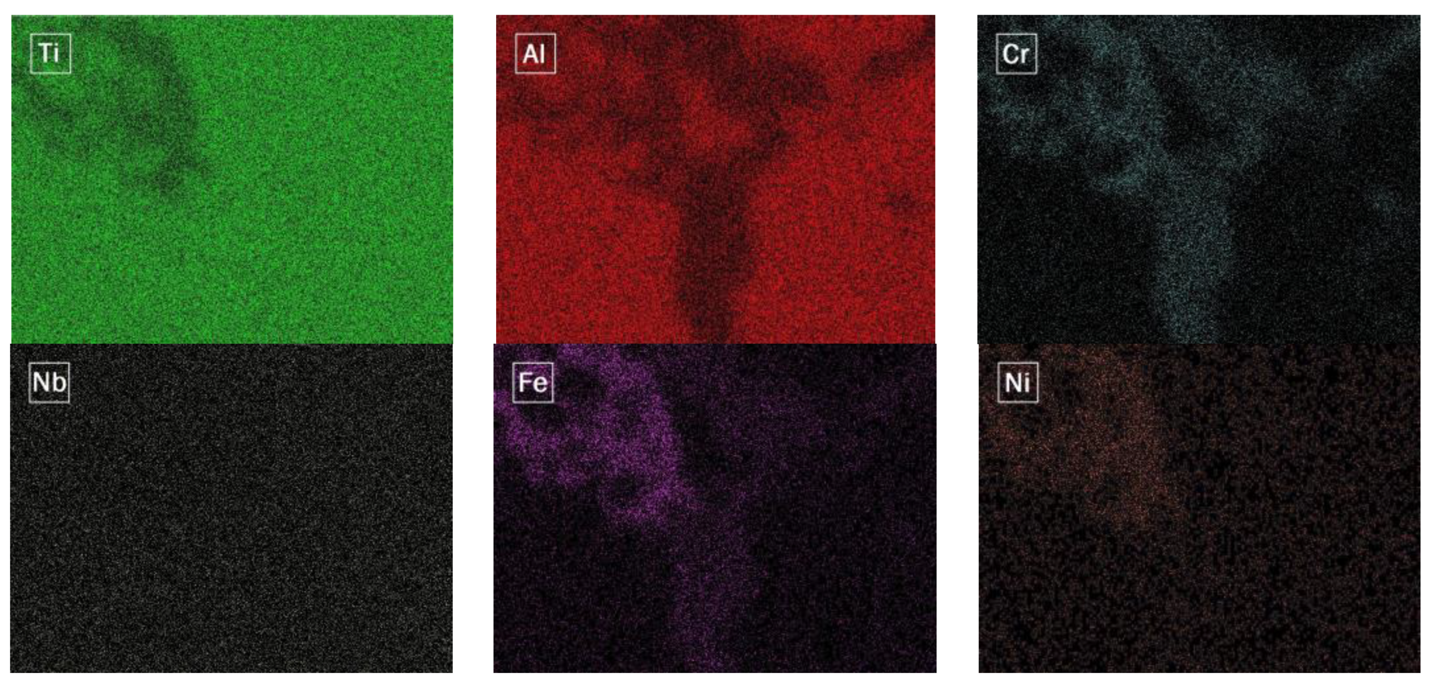
  • The diffusion of elements from the baseplate to the densified material led to the formation of some intermetallics and phases containing Ti, Al, Fe, and Ni, whose high hardness may explain the characteristic brittleness of the formed interface.
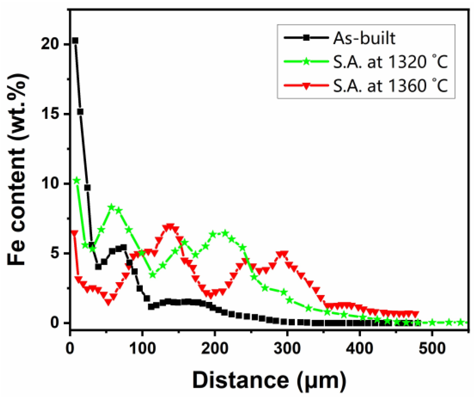
  • The diffusion length of Fe in the as-built condition was about 350 μm. However, in the samples solution-annealed at 1320 °C and 1360 °C, it was about 450 μm and >500 μm, respectively.
  • Hardness results showed that the matrix of the sample that was solution annealed at the higher temperature had more uniform and higher hardness values.
  • XRD patterns confirmed the formation of some compounds close to the interface of the baseplate and the deposited material.
Therefore, manufacturing samples of TiAl on a stainless steel baseplate give us the ability to detach the fabricated samples by applying a low bending force. However, it should be noted that removing the first deposited layers (about 350 μm) before applying any potential post-processing heat treatment is recommended to avoid any further diffusion of Fe into the part and a consequential negative effect on the behavior of the material. Due to the limitations in identifying the specific compounds formed at the interface region, future work can employ other techniques, such as TEM and electron diffraction patterns, to better characterize these phases.

Author Contributions

Conceptualization, E.B., D.U. and S.B.; methodology, E.B., M.S.K. and C.G.; investigation, M.S.K., C.G. and G.M.; data curation, M.S.K.; writing—original draft preparation, M.S.K.; writing—review and editing, E.B.; supervision, D.U. and S.B.; funding acquisition, S.B. All authors have read and agreed to the published version of the manuscript.

Funding

This research received no external funding.

Data Availability Statement

The data presented in this study are available upon request from the corresponding author.

Conflicts of Interest

The authors declare no conflict of interest.

References

  1. Baudana, G.; Biamino, S.; Klöden, B.; Kirchner, A.; Weißgärber, T.; Kieback, B.; Pavese, M.; Ugues, D.; Fino, P.; Badini, C. Electron Beam Melting of Ti-48Al-2Nb-0.7Cr-0.3Si: Feasibility investigation. Intermetallics 2016, 73, 43–49. [Google Scholar] [CrossRef]
  2. Dzogbewu, T.C.; du Preez, W.B. Additive Manufacturing of Ti-Based Intermetallic Alloys: A Review and Conceptualization of a Next-Generation Machine. Materials 2021, 14, 4317. [Google Scholar] [CrossRef] [PubMed]
  3. Bewlay, B.P.; Nag, S.; Suzuki, A.; Weimer, M.J. TiAl alloys in commercial aircraft engines. Mater. High Temp. 2016, 33, 549–559. [Google Scholar] [CrossRef]
  4. Wu, X. Review of alloy and process development of TiAl alloys. Intermetallics 2006, 14, 1114–1122. [Google Scholar] [CrossRef]
  5. Chen, W.; Li, Z. 11—Additive manufacturing of titanium aluminides. In Additive Manufacturing for the Aerospace Industry; Froes, F., Boyer, R., Eds.; Elsevier: Amsterdam, The Netherlands, 2019; pp. 235–263. [Google Scholar] [CrossRef]
  6. Clemens, H.; Wallgram, W.; Kremmer, S.; Güther, V.; Otto, A.; Bartels, A. Design of Novel β-Solidifying TiAl Alloys with Adjustable β/B2-Phase Fraction and Excellent Hot-Workability. Adv. Eng. Mater. 2008, 10, 707–713. [Google Scholar] [CrossRef]
  7. Dahara, M.S.; Tamirisakandalab, S.A.; Lewandowskia, J.J. Fatigue crack growth and fracture behavior of as-cast Ti-43.5AL-4Nb-1Mo-0.1B (TNM) compared to TI-48AL-2Nb-2Cr (4822) (POSTPRINT). Intermetallics 2017, 91, 158–168. [Google Scholar] [CrossRef]
  8. Fritz Appel, J.D.H.P.; Oehring, M. Gamma Titanium Aluminide Alloys: Science and Technology; John Wiley & Sons: New York, NY, USA, 2011. [Google Scholar]
  9. Raji, S.A.; Popoola, A.P.I.; Pityana, S.L.; Popoola, O.M. Characteristic effects of alloying elements on β solidifying titanium aluminides: A review. Heliyon 2020, 6, e04463. [Google Scholar] [CrossRef]
  10. Wimler, D.; Käsznar, K.; Musi, M.; Breuning, C.; Markl, M.; Keckes, J.; Clemens, H.; Körner, C.; Mayer, S. How electron beam melting tailors the Al-sensitive microstructure and mechanical response of a novel process-adapted γ-TiAl based alloy. Mater. Design 2021, 212, 110187. [Google Scholar] [CrossRef]
  11. Bourell, D.L.; Rosen, D.W.; Leu, M.C. The Roadmap for Additive Manufacturing and Its Impact. 3D Print. Addit. Manuf. 2014, 1, 6–9. [Google Scholar] [CrossRef]
  12. DebRoy, T.; Wei, H.L.; Zuback, J.S.; Mukherjee, T.; Elmer, J.W.; Milewski, J.O.; Beese, A.M.; Wilson-Heid, A.; De, A.; Zhang, W. Additive manufacturing of metallic components—Process, structure and properties. Prog. Mater. Sci. 2018, 92, 112–224. [Google Scholar] [CrossRef]
  13. Galati, M.; Iuliano, L. A literature review of powder-based electron beam melting focusing on numerical simulations. Addit. Manuf. 2018, 19, 1–20. [Google Scholar] [CrossRef]
  14. Herzog, D.; Seyda, V.; Wycisk, E.; Emmelmann, C. Additive manufacturing of metals. Acta Mater. 2016, 117, 371–392. [Google Scholar] [CrossRef]
  15. Körner, C. Additive manufacturing of metallic components by selective electron beam melting—A review. Int. Mater. Rev. 2016, 61, 361–377. [Google Scholar] [CrossRef] [Green Version]
  16. Larsson Morgan, L.U.; Ola, H. Rapid manufacturing with electron beam melting (EBM)—A manufacturing revolution? Solid Free. Fabr. Symp. 2003, 438–443. [Google Scholar]
  17. Cormier, D.; Harrysson, O.; Mahale, T.; West, H. Freeform Fabrication of Titanium Aluminide via Electron Beam Melting Using Prealloyed and Blended Powders. Res. Lett. Mater. Sci. 2007, 2007, 034737. [Google Scholar] [CrossRef]
  18. Murr, L.E.; Gaytan, S.M.; Ceylan, A.; Martinez, E.; Martinez, J.L.; Hernandez, D.H.; Machado, B.I.; Ramirez, D.A.; Medina, F.; Collins, S.; et al. Characterization of titanium aluminide alloy components fabricated by additive manufacturing using electron beam melting. Acta Mater. 2010, 58, 1887–1894. [Google Scholar] [CrossRef]
  19. Schwerdtfeger, J.; Körner, C. Selective electron beam melting of Ti–48Al–2Nb–2Cr: Microstructure and aluminium loss. Intermetallics 2014, 49, 29–35. [Google Scholar] [CrossRef]
  20. Biamino, S.; Penna, A.; Ackelid, U.; Sabbadini, S.; Tassa, O.; Fino, P.; Pavese, M.; Gennaro, P.; Badini, C. Electron beam melting of Ti–48Al–2Cr–2Nb alloy: Microstructure and mechanical properties investigation. Intermetallics 2011, 19, 776–781. [Google Scholar] [CrossRef]
  21. Cho, K.; Kawabata, H.; Hayashi, T.; Yasuda, H.Y.; Nakashima, H.; Takeyama, M.; Nakano, T. Peculiar microstructural evolution and tensile properties of β-containing γ-TiAl alloys fabricated by electron beam melting. Addit. Manuf. 2021, 46, 102091. [Google Scholar] [CrossRef]
  22. Kan, W.; Chen, B.; Jin, C.; Peng, H.; Lin, J. Microstructure and mechanical properties of a high Nb-TiAl alloy fabricated by electron beam melting. Mater. Design 2018, 160, 611–623. [Google Scholar] [CrossRef]
  23. Galati, M.; Rizza, G.; Salmi, A.; Biamino, S.; Ghibaudo, C.; Fino, P.; Iuliano, L. Residual stress investigation on Ti-48Al-2Cr-2Nb samples produced by Electron Beam Melting process. Procedia CIRP 2021, 99, 336–341. [Google Scholar] [CrossRef]
  24. Bieske, J.; Franke, M.; Schloffer, M.; Körner, C. Microstructure and properties of TiAl processed via an electron beam powder bed fusion capsule technology. Intermetallics 2020, 126, 106929. [Google Scholar] [CrossRef]
  25. Mishin, Y.; Herzig, C. Diffusion in the Ti–Al system. Acta Mater. 2000, 48, 589–623. [Google Scholar] [CrossRef]
  26. Herzig, C.; Przeorski, T.; Friesel, M.; Hisker, F.; Divinski, S. Tracer solute diffusion of Nb, Zr, Cr, Fe, and Ni in γ-TiAl: Effect of preferential site occupation. Intermetallics 2001, 9, 461–472. [Google Scholar] [CrossRef]
  27. Hao, Y.L.; Xu, D.S.; Cui, Y.Y.; Yang, R.; Li, D. The site occupancies of alloying elements in TiAl and Ti3Al alloys. Acta Mater. 1999, 47, 1129–1139. [Google Scholar] [CrossRef]
  28. Przeorski, T.; Friesel, M.; Hisker, F.; Divinski, S.V.; Herzig, C. Solute Diffusion in the Intermetallic Compound γ-TiAl. Defect Diffus. Forum 2001, 194–199, 493–498. [Google Scholar] [CrossRef]
  29. Divinski, S.V.; Herzig, C.; Klinkenberg, C. Tracer diffusion of niobium and titanium in binary and ternary titanium aluminides. J. Phase Equilibria Diffus. 2005, 26, 452–457. [Google Scholar] [CrossRef]
  30. Ghibaudo, C.; Wartbichler, R.; Marchese, G.; Clemens, H.; Ugues, D.; Biamino, S. Influence of focus offset on the microstructure of an intermetallic γ-TiAl based alloy produced by electron beam powder bed fusion. J. Manuf. Process. 2023, 89, 132–141. [Google Scholar] [CrossRef]
  31. Brotzu, A.; Felli, F.; Pilone, D. Effect of alloying elements on the behaviour of TiAl-based alloys. Intermetallics 2014, 54, 176–180. [Google Scholar] [CrossRef]
  32. Shu, S.; Qiu, F.; Tong, C.; Shan, X.; Jiang, Q. Effects of Fe, Co and Ni elements on the ductility of TiAl alloy. J. Alloys Compd. 2014, 617, 302–305. [Google Scholar] [CrossRef]
  33. Nová, K.; Novák, P.; Arzel, A.; Průša, F. Alloying of Fe-Al-Si Alloys by Nickel and Titanium. Manuf. Technol. J. 2018, 18, 645–649. [Google Scholar] [CrossRef]
  34. Simões, S.; Tavares, C.J.; Guedes, A. Joining of γ-TiAl Alloy to Ni-Based Superalloy Using Ag-Cu Sputtered Coated Ti Brazing Filler Foil. Metals 2018, 8, 723. [Google Scholar] [CrossRef] [Green Version]
Figure 1. Particle size distribution of the powder used in this study.
Metals 13 00772 g001
Figure 2. SEM micrographs of (a) as-built and (b) HIPed samples along the building direction.
Metals 13 00772 g002
Figure 3. Microstructure of the cross-sections of samples solution annealed at (a) 1320 and (b) 1360 °C.
Metals 13 00772 g003
Figure 4. (a) SEM micrograph of the as-built condition, (b) distribution of different elements along the building direction (from left to right), and (c) the region with higher magnification.
Metals 13 00772 g004
Figure 5. EDS mapping of the area in Figure 4c.
Metals 13 00772 g005
Figure 6. Fe content along the building direction in the three different conditions.
Metals 13 00772 g006
Figure 7. Microhardness indentations on (a) as-built, (b) HIPed samples, and the samples solution annealed at (c) 1320 and (d) 1360 °C.
Metals 13 00772 g007
Figure 8. Microhardness maps of (a) as-built, (b) HIPed samples, and the samples solution annealed at (c) 1320 and (d) 1360 °C.
Metals 13 00772 g008
Figure 9. XRD patterns of HIPed sample at different locations along the building direction.
Metals 13 00772 g009
Figure 10. XRD patterns of the samples heat-treated under different conditions (samples were cut along the building direction).
Metals 13 00772 g010
Table 1. Chemical composition (at.%) of the pre-alloyed powder determined by OES-ICP analysis.
ElementTiAlCrNb
PowderBal.48.71.92.0
Table 2. Chemical composition (in wt.%) of different regions of Figure 4c.
ElementTiAlNbCrFeNi
Area 146.9 ± 0.2329.2 ± 0.184.5 ± 0.27.7 ± 0.148.2 ± 0.163.4 ± 0.15
Area 260.7 ± 0.2420.5 ± 0.154.5 ± 0.29.4 ± 0.154.4 ± 0.140.4 ± 0.11
Matrix59.8 ± 0.2331.5 ± 0.185.3 ± 0.22.3 ± 0.10.9 ± 0.10.2 ± 0.11
Table 3. Average hardness values (HV 0.1) measured for each sample.
Conditionas-BuiltHIPedHeat Treated at 1320 °CHeat Treated at 1360 °C
Hardness321.2431.4440.8435.6
Standard Deviation112.7114.8123.477.7
Disclaimer/Publisher’s Note: The statements, opinions and data contained in all publications are solely those of the individual author(s) and contributor(s) and not of MDPI and/or the editor(s). MDPI and/or the editor(s) disclaim responsibility for any injury to people or property resulting from any ideas, methods, instructions or products referred to in the content.

