Article

The Impact of High-Speed and Thermal-Assisted Machining on Tool Wear and Surface Roughness during Milling of SKD11 Steel

1
Faculty of Mechanical Engineering, Hungyen University of Technology and Education, Hungyen 100000, Vietnam
2
School of Mechanical Engineering, Hanoi University of Science and Technology, 1A-Dai Co Viet Street, Hai Ba Trung District, Hanoi 100000, Vietnam
*
Author to whom correspondence should be addressed.
Metals 2023, 13(5), 971; https://doi.org/10.3390/met13050971
Submission received: 11 April 2023 / Revised: 14 May 2023 / Accepted: 16 May 2023 / Published: 17 May 2023
(This article belongs to the Section Metal Casting, Forming and Heat Treatment)

Abstract

:
This research investigates the impact of high-speed and thermal-assisted machining (HS-TAM) on tool wear and surface roughness during the milling of SKD11 steel. The goal is to identify high-speed and elevated temperature zones that can improve machining efficiency, enhance surface quality, minimize costs, and extend tool life. The study involves the high-speed milling of SKD11 steel at various temperature conditions to evaluate the effect of temperature on tool wear and surface roughness. Additionally, experiments are conducted at the highest allowable support temperature with increased high-speed cutting to examine the effect of high speed on tool wear and surface roughness. The study demonstrates the correlation between cutting-tool wear and surface roughness at various high-speed cutting conditions and TAM environments and provides recommendations for cutting speeds and heating temperatures for different quality and productivity objectives. The findings indicate that high-speed milling of SKD11 at 600 m/min and 500 °C can decrease cutting tool-wear height (wear volume) and surface roughness by 82.47% (95.74%) and 91.08%, respectively, compared to machining at room temperature. Furthermore, the higher-speed modes at 500 °C result in a slight increase in wear height and surface roughness for high-speed cutting below 800 m/min, but reduces surface roughness for high-speed cutting beyond 800 m/min, reaching a value of 0.158 µm at the high-speed cutting limit of 1000 m/min.

1. Introduction

Manufacturing processes aim to produce high-quality and efficiently machined products. High-speed machining is an advanced technology that can produce high-precision products and reduce the costs associated with the assembly and storage of fixtures [1]. High-speed machining offers advantages such as fast metal removal rate leading to increased machining productivity, low cutting force, and good surface quality [2,3,4,5]. During high-speed machining, the chip moves out of the cutting zone faster, significantly reducing the cutting heat because the cutting heat is transferred mainly to the chip [6]. However, tool wear and product surface quality are important parameters in high-speed machining. Tool wear is a complex process caused by the simultaneous action of the mechanical and thermal stresses of the cutting tool. The main cause of cutting-tool wear is friction and increased temperature due to friction at the contact area between the cutting tool, chip, and workpiece. The mechanism of cutting-tool wear is described by Xianhua Tian et al. [7]. High-speed machining is mainly applied in the mold industry, automobile industry, aviation industry, and light industry. However, high-speed machining also has some disadvantages, such as the need to carefully select the cutting mode, the cutting tool, the initial cost of equipment, and the cost of wear and maintenance of the machine. In addition, the spindle of the machine must be balanced dynamically.
Thermal-assisted machining (TAM), also known as machining assisted by heating or hot machining, was first introduced at the turn of the century [8]. The advantages of the heating process can overcome some of the limitations of high-speed machining. Studies have shown outstanding results compared to conventional machining methods, such as increased productivity, increased surface quality, more cutting performance, increased tool life, reduced vibration during cutting, and reduced cutting forces [9,10,11,12,13,14,15,16]. Therefore, the benefits of the heating process have made it an attractive research area. In this study, we evaluate the cutting ability of uncoated carbide cutters to mill SKD11 steel at room temperature and high temperature, respectively, to evaluate the cutting ability under normal machining and hot machining. The two output parameters are the amount of tool wear, which represents tool life, and the surface roughness, which characterizes the quality of the analyzed product under different temperature conditions [17,18,19,20,21,22,23,24,25,26,27,28].
Previous studies have shown the benefits of HS-TAM on tool life and surface quality for different materials. For example, L. Ozler et al. [17] investigated tool life when processing austenitic-manganese steel and found that the workpiece temperature is directly proportional to tool life while cutting speed is inversely proportional. Similarly, Ginta et al. [18] analyzed the benefits of heat machining on the machinability of titanium alloy Ti-6Al-4V and found that heat treatment significantly increases tool life and the material-removal rate. Chang et al. [19] studied the surface roughness when machining Al2O3 workpieces in a laser-heating environment and established an optimal set of technological parameters using the Taguchi method. These studies demonstrate the potential of HS-TAM in improving machining efficiency and quality.
Tool wear is a multifaceted process that arises from a combination of physical and chemical phenomena in the contact zone between the tool, chip, and workpiece. The deformation, heat, and forces generated by wear often cause changes to the shape and geometrical properties of the cutting region of the tool, particularly in high-speed machining operations where wear rates and cutting forces are significantly higher than those encountered in low-speed machining [1]. In such scenarios, the use of high-hardness coatings and costly materials, such as alloy flakes, polycrystalline diamond (PCD) tools, TiN-coated high-speed steel (HSS), and coated cemented carbide tools, are often necessary to enhance tool life and minimize wear, particularly when processing high-hardness workpieces. Notably, numerous studies have explored the application of various cutting tools to SKD11 steel. For example, CVD-coated tools with double layers of Al2O3/Ti(C,N) have been employed with cutting speeds ranging from 90–180 m/min as have TiN-coated ceramic inserts with cutting speeds of 75–125 m/min, and TiSiN-coated milling tools with a maximum cutting speed range of 300 m/min [5,13,20]. Despite the use of carbide-coated cutting tools, considerable wear persists, and wear rates increase as speed escalates, making it imperative to identify a solution that utilizes ordinary cutting tools to facilitate high-speed machining of hard materials [1].
This study investigates the impact of high-speed and thermal-assisted machining (HS-TAM) on tool wear and surface roughness when milling SKD11 steel. The aim is to identify optimal high-speed and elevated temperature zones that can enhance surface quality, improve machining efficiency, minimize costs, and extend tool life. The study involves the high-speed milling of SKD11 steel at various temperature conditions, including the highest allowable support temperature, to assess the effect of temperature on tool wear and surface roughness. The correlation between cutting-tool wear and surface roughness at various high-speed cutting and TAM conditions is investigated, and recommendations are provided for cutting speeds and temperature conditions for different quality and productivity objectives. The findings show that high-speed milling of SKD11 at 600 m/min and 500 °C can significantly decrease cutting tool-wear height and surface roughness compared to machining at room temperature. The study provides new insights into the relationship between temperature, cutting speed, tool wear, and surface roughness, and it can assist manufacturers in optimizing their milling process to achieve quality and productivity goals.

2. Methodology

2.1. Material

This study focuses on investigating the effects of HS-TAM on tool wear and surface roughness during the milling of SKD11 steel a commonly used material in the production of extrusion molds, plastic injection molds, and pressure casting molds due to its high hardness, compressive strength, impact toughness, and deformation resistance. A billet of SKD11 alloy steel, with dimensions of 70 × 80 × 31 (mm × mm × mm) and a hardness of 250 HB, was used in accordance with the JIS-G4404 standard from Japan. The chemical composition of the material is presented in Table 1. Previous research [24] examined the impact of heating the workpiece to different temperatures and allowing it to cool naturally in the air. The hardness of the samples was measured using a Brinell hardness tester, and the corresponding microstructures were imaged and analyzed using a microscope. The results indicate that the change in hardness of the material after heating is negligible, and the microstructure of the material remains unchanged compared to the original sample.

2.2. Experimental Setup

The experiment was conducted using Taiwan’s MC500 high-speed milling machine (Fuhong Machinery Co., New Taipei, Taiwan) with a spindle rotation speed of 100–30,000 rpm, a spindle capacity of 15 kW, a movement speed of the machine table when processing 1 ÷ 30,000 m/min, a maximum idle speed of 48,000 mm/min, and the displacement of the machine plate X × Y × Z = 500 mm × 400 mm × 300 mm. An electromagnetic induction-heating system was used to heat the workpiece just before machining, which consisted of a high-frequency heating circuit and a temperature controller. The temperature sensor was used to measure and send feedback on temperature information to the controller, which helped maintain constant temperature control throughout the machining process. A hard-alloy cutting piece without carbide code APKT1604 PDER-MA-HO1 from KORLOY (Šumperk, Czech Republic) was used, and a coolant was not used during machining. To assess the amount of wear on the cutting piece after each machining, the study used two methods: weighing the wear and measuring the wear height of the cutting piece. The weight of the hard-alloy cutting piece was measured using a microbalance AJ-3002 (Vibra Shinko, Denshi, Japan), and the wear height was measured on an HD-30AX (Mitutoyo, Kawasaki, Japan) series high-precision digital microscope. The surface roughness of the workpiece after machining was measured using a SJ-210 (Mitutoyo, Kawasaki, Japan) roughness measuring device. The experimental setup and test equipment are shown in Figure 1 and Figure 2, respectively.

3. Results and Discussions

3.1. Influence of the TAM Process on Cutting-Tool Wear during High-Speed Milling of SKD11

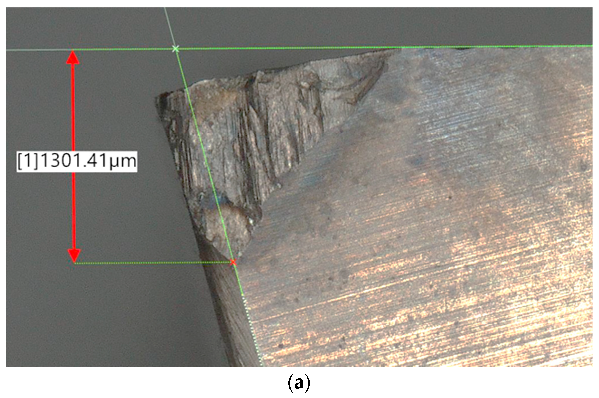
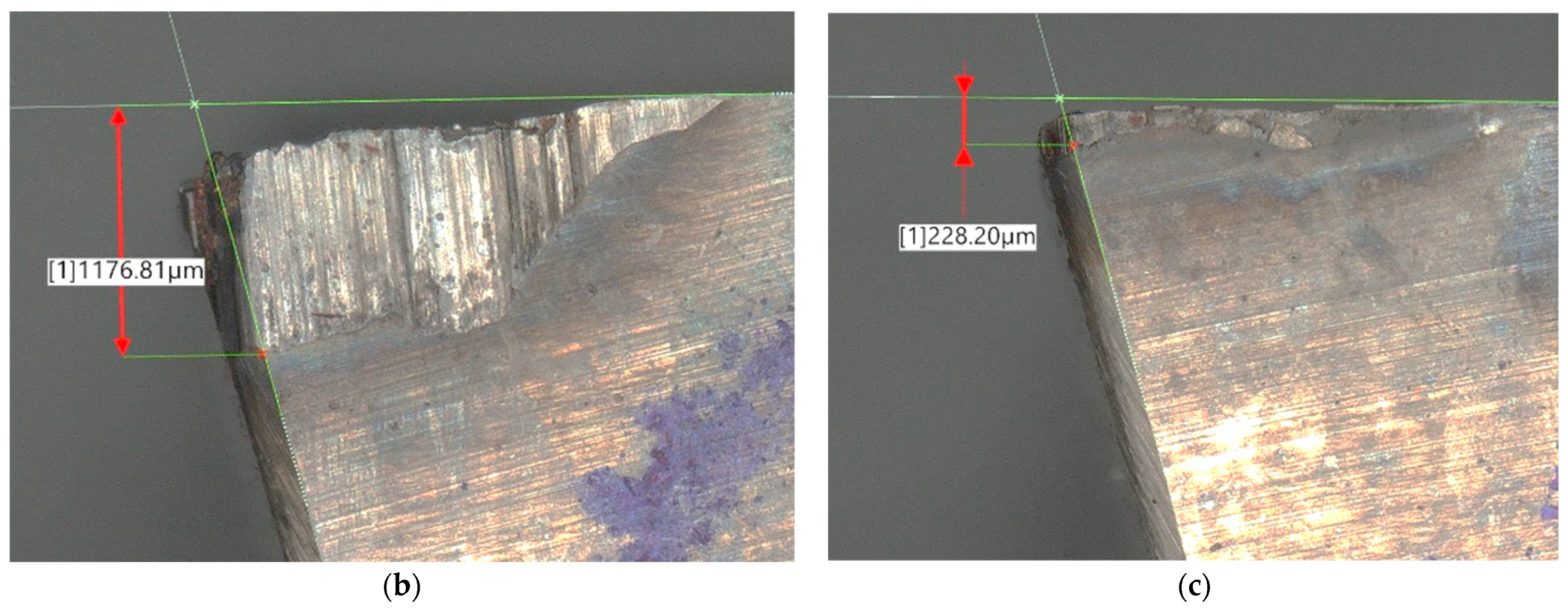
In this study, the effect of thermal-assisted machining (TAM) on the tool wear of a non-carbide-coated cutting tool when milling SKD11 steel at high speeds was investigated. Figure 3 shows an image of a hard-alloy steel tool (code APKT1604 PDER-MA-HO1) utilized for milling SKD11 steel at room temperature and elevated temperatures with a cutting mode of V = 600 m/min, feed rate f = 802 mm/min, and depth of cut t = 1.5 mm. The results showed that milling at room temperature led to severe wear on the cutting tool, resulting in tool breakage with a measured wear height of 1301 µm (Figure 3a). To address this issue, the present study investigated the effect of TAM on cutting-tool wear during high-speed milling of SKD11 steel, while minimizing tool costs and maintaining product quality. The experiments were carried out using the same hard-alloy steel tool (code APKT1604 PDER-MA-HO1) with the cutting mode of V = 600 m/min, feed rate f = 802 mm/min, and depth of cut t = 1.5 mm. The TAM method was conducted by heating the workpiece to various temperature conditions ranging from 200 °C to 500 °C to evaluate the impact of thermal assistance as shown in Figure 3b,c. The results (Table 2) showed that the use of non-carbide-coated cutting tools to mill SKD11 steel in a TAM environment resulted in a good-performing cutting process. The wear weight and wear height of the cutting tool decreased significantly as the workpiece temperature increased. The wear rate was most rapid in the temperature range from 250 °C to 350 °C. At a temperature of 500 °C, the wear weight did not change, but the wear height continued to decrease. However, the amount of wear-height reduction was lower than that when changing the temperature in the previous range. The results showed that non-carbide-coated cutting pieces were able to mill SKD11 steel effectively even in TAM environments. Thus, the use of non-carbide-coated cutting tools at elevated temperatures shows higher economic efficiency than conventional machining without sacrificing machinability. Table 2 provides details of the cutting mode, temperature conditions, and tool-wear results. The percentage of wear weight and height of the cutting tool in TAM compared to room-temperature machining was calculated using Formulas (1) and (2), respectively.
Δ m W T % = m w R m w T m w R × 100
Δ H W T % = H w R H w T H w R × 100
where: Δ m W T and Δ H W T represent the percentage reduction of wear weight and wear height, respectively. Additionally, m w R and m w T are the tool-wear weight (measured in grams) when milling at room temperature (R) and high temperature (T), respectively. Similarly, H w R and H w T refer to the tool-wear height (measured in micrometers) when milling at room temperature (R) and high temperature(T), respectively.
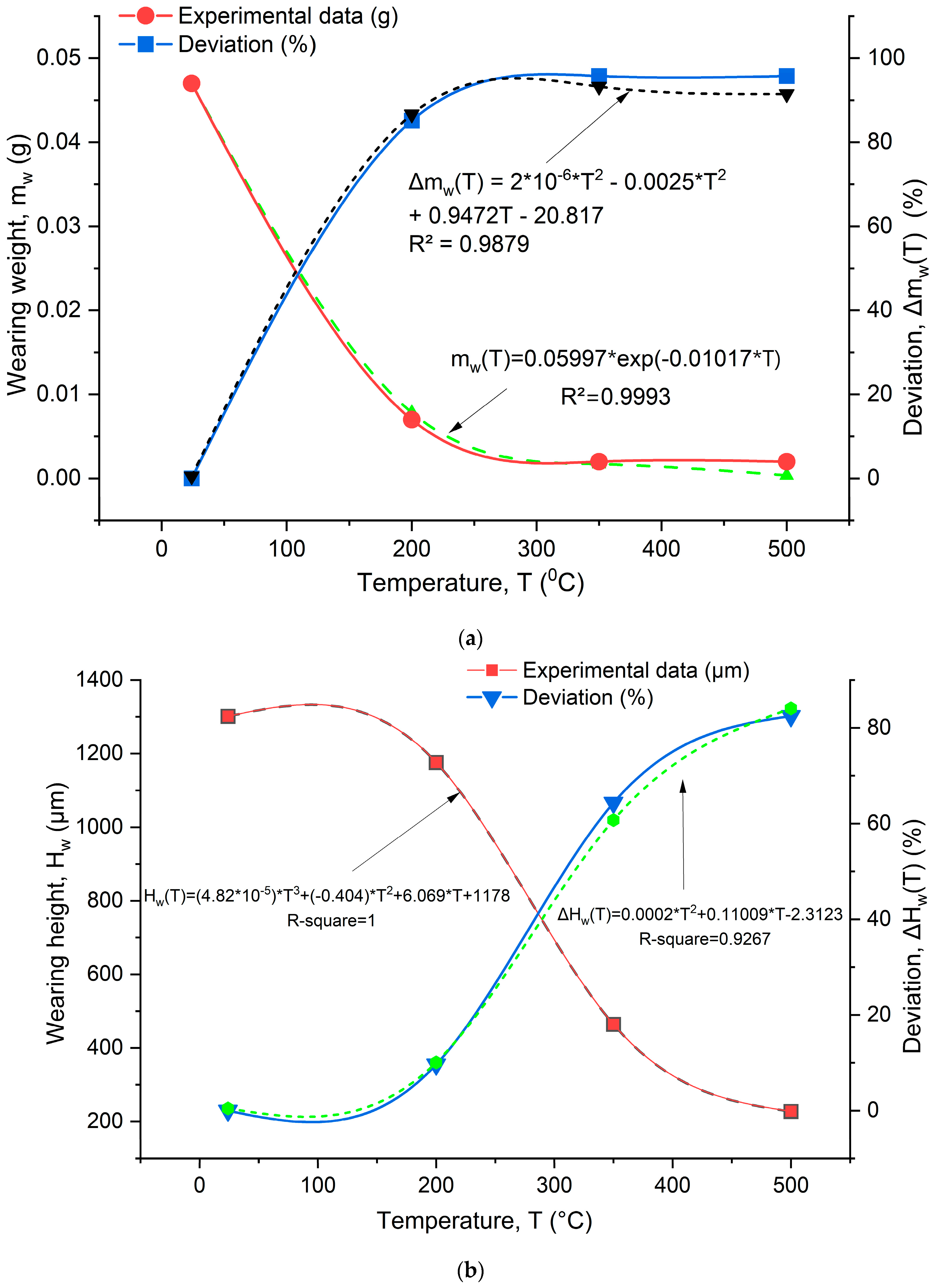
Figure 4 depicts the effects of thermal-assisted milling (TAM) on cutting wear and wear reduction. Increasing the TAM temperature significantly reduces the wear weight and height of the cutting tool. At room temperature, tool wear decreases due to piece breakage. However, at 200 °C, the cutting tool wears quickly. It has a large wear height but does not break. As the workpiece temperature rises to 350 °C, wear weight and wear height continue to decrease sharply. The wear-height graph shows the steepest slope in the temperature range from room temperature to 350 °C, indicating a rapid wear rate in this range. Within a heating range from 350 °C to 500 °C, the wear weight does not change, but the wear height continues to decrease at a lower rate. Increasing the TAM temperature decreases the wear rate. At 500 °C, the tool-wear height and wear weight improve by 82.47% and 95.74%, respectively. Thus, the TAM process significantly enhances tool wear when milling SKD11 steel. The study determined that the appropriate processing temperature for SKD11 steel is 500 °C to maintain the material’s microstructure and improve the cutting tool’s durability and lifespan. The amount of wear height directly affects the machining surface roughness and was chosen as a measurement criterion for analysis and evaluation of the input and output parameters of the machining process.

3.2. Influence of the High-Speed Cutting on Tool Wear in TAM Process for SKD11 Steel

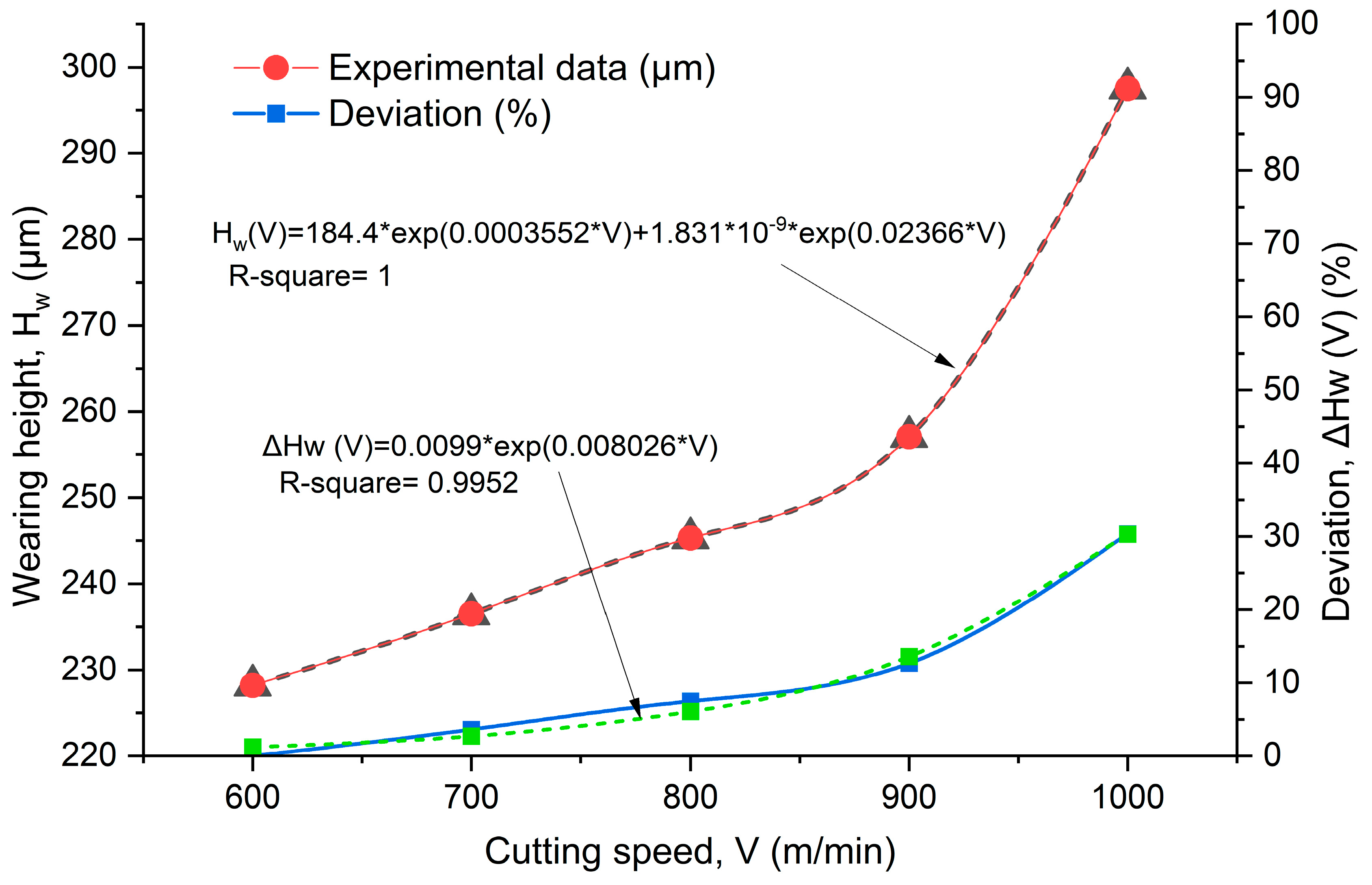
Previous research has shown that high temperatures can reduce the amount of tool wear in SKD11 steel. To further investigate the effect of cutting speed on wear amount, the present study evaluates the impact of high-speed cutting on tool wear when milling SKD11 steel in a TAM environment of 500 °C. The experiments were carried out with a constant feed rate and a fixed depth of cut (f = 802 mm/min, t = 1.5 mm). The workpiece was heated to 500 °C, with the cutting speed gradually increasing from 600 m/min up to 1100 m/min. The results of the experiments are presented in Figure 5 and Table 3, which show the cutting mode and the cutting-wear measurement (Hw) at different high-speed cuttings. The percentage deviation in wear height (ΔHw−V) is calculated by Formula (3).
Δ H W V % = H w V H w 600 H w 600 × 100
where Hw−600 and Hw−V are the wear height when machining at a cutting speed of 600 m/min and various cutting speeds, respectively.
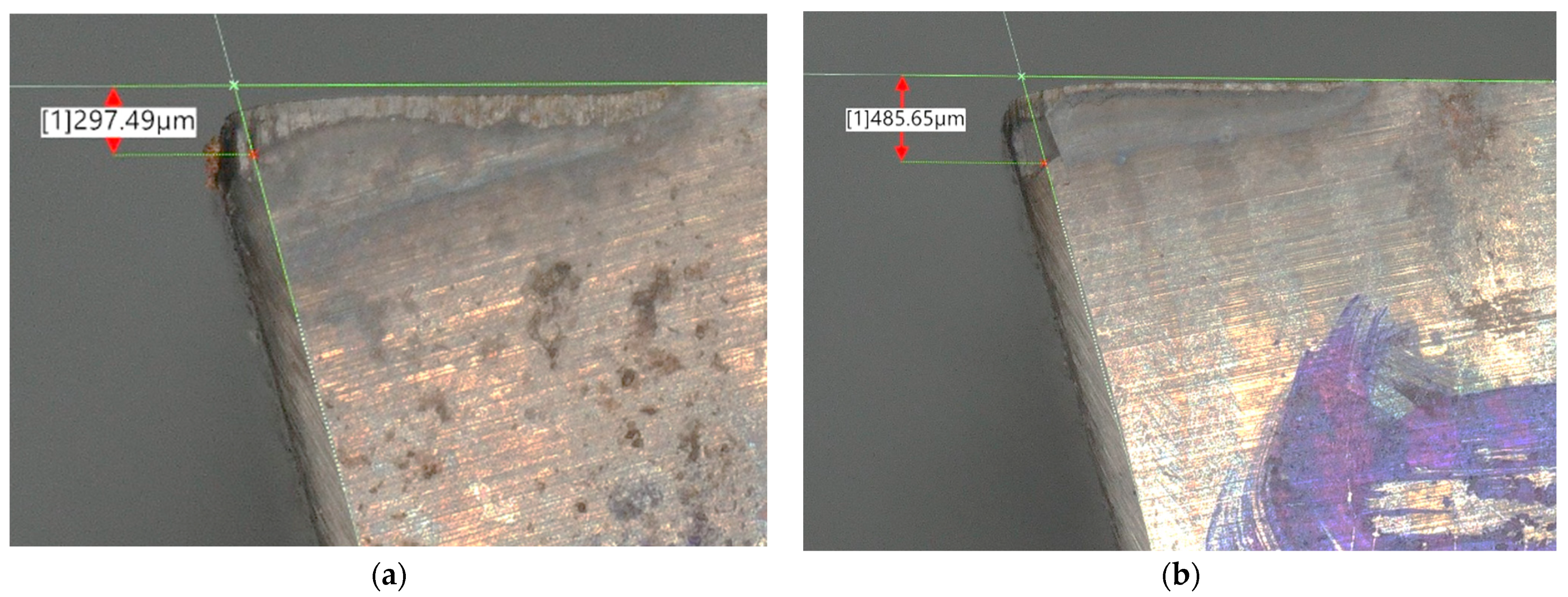
Figure 5 shows the wear of the cut piece during high-speed milling with TAM at V = 1000 m/min and V = 1100 m/min. It was observed that at the limited heating temperature of 500 °C and a cutting speed of up to 1100 m/min, the wear height increased sharply (485.64 µm), and the cut piece broke. Therefore, the cutting speed when high-speed milling with SKD11 steel heating should be 1000 m/min or less.
Figure 6 illustrates the variation of tool wear at different cutting speeds. The results indicate that when the cutting speed is increased from 600 m/min to 1000 m/min with a TAM of 500 °C, the wear rate remains stable. The wear rate seems to follow a linear law when the cutting speed is in the range of 600–900 m/min. However, when the cutting speed exceeds 900 m/min, the wear rate is accelerated, indicating that the tool-wear rate also increases with increasing cutting speed. The wear rate did not change significantly when the cutting speed was varied in the range of 600–1000 m/min with step changes of 100 m/min. As the cutting speed was increased from 600 to 700, 800, 900, and 1000 m/min, there was a step-wise increase in the tool-wear height by 8.3, 17.1, 28.9, and 69.3 µm, which corresponds to 3.6, 7.5, 12.7, and 30.4%, respectively.

3.3. Influence of TAM Process and High-Speed Cutting on Surface Roughness during Milling of SKD11 Steel

In the field of mechanical machining, tool wear directly affects the roughness of the surface being machined. The purpose of this study is to explore the connection between high-speed milling, temperature-assisted machining (TAM), and surface roughness. The roughness of a machined surface has a significant impact on its usefulness and determines factors such as durability, hardness, wear resistance, and heat resistance. This study used non-carbide-coated cutting tools to perform high-speed machining under the same cutting conditions (V = 600 m/min, f = 802 mm/min, t = 1.5 mm) at various elevated temperature levels ranging from room temperature to 500 °C to evaluate the effect of TAM on surface roughness.
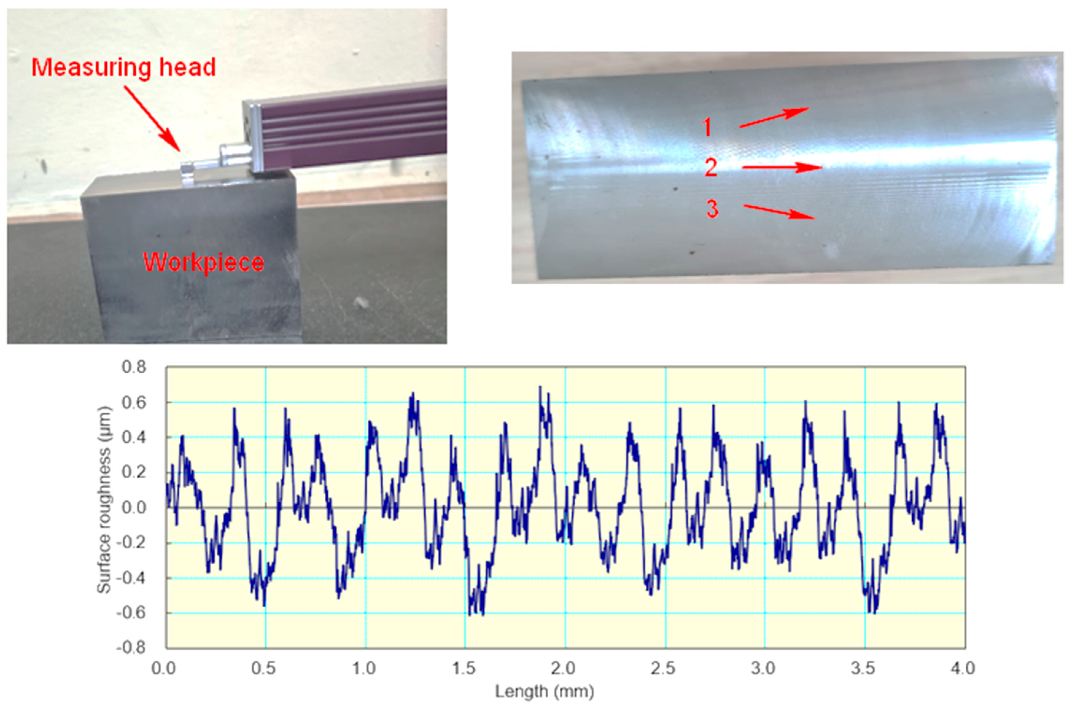
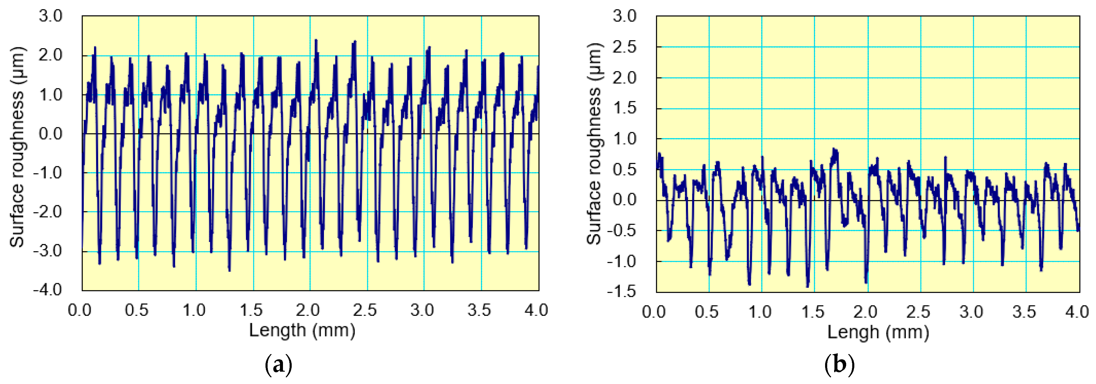
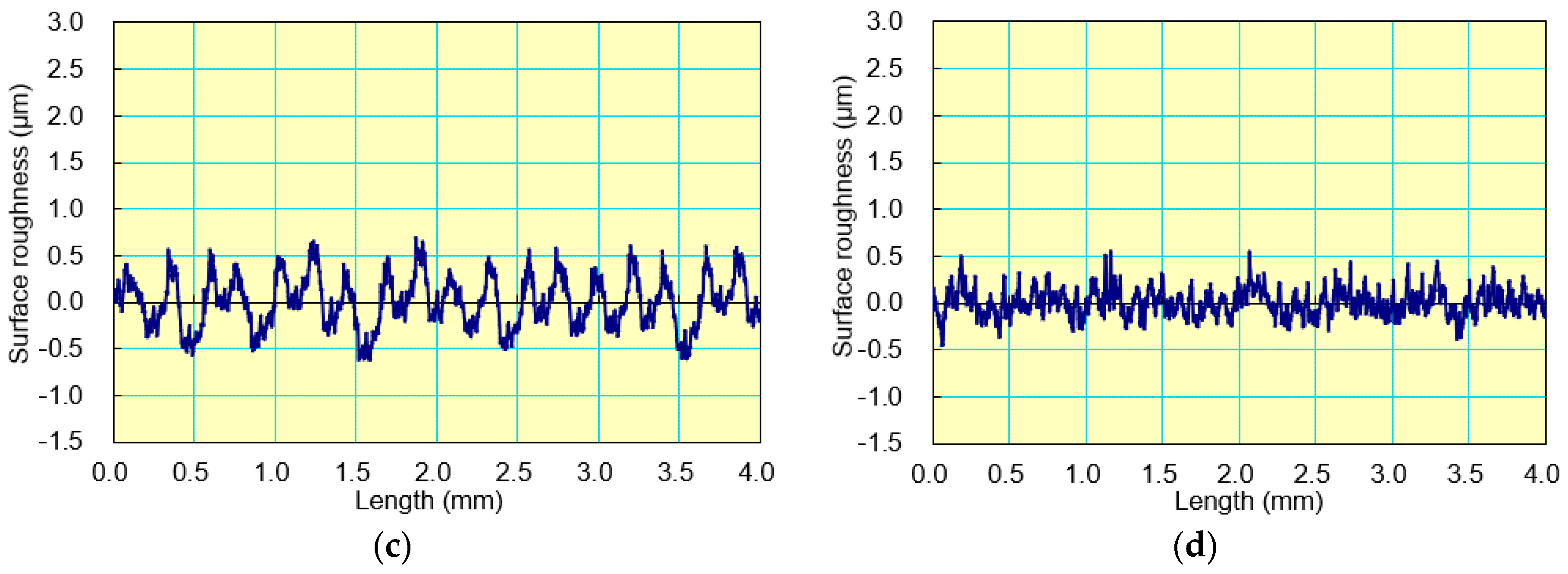
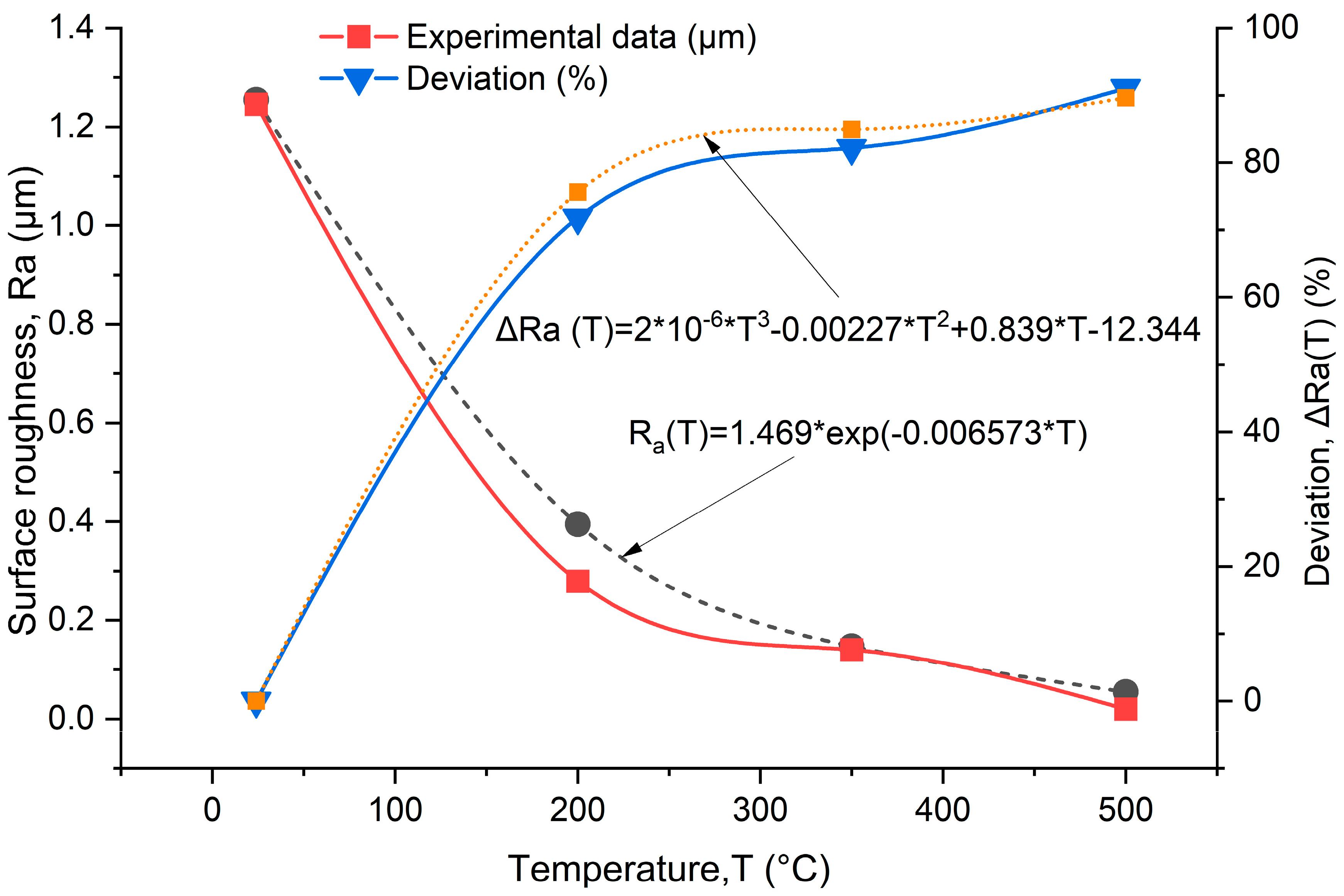
Figure 7 shows the measurement method and the results of the surface roughness profile. The average roughness criterion was used according to ISO standards to assess surface quality, with semi-finished machined surfaces classified as roughness levels 5–7 and finishing processing classified as roughness levels 8–10. To ensure accuracy, roughness was measured at three positions (1, 2, and 3) and the results were averaged. The measurement direction was perpendicular to the machining trace. Table 4 presents the cutting conditions, temperature levels, and average surface roughness results. The percentage variations in surface roughness are calculated using Formula (4). Figure 8 shows the surface roughness profile image when machining at room temperature, 200 °C, 350 °C, and 500 °C on the same magnitude of coordinate axes. The relationship between temperature and surface roughness is shown in Figure 9, which indicates that as the temperature increases, the surface roughness decreases. At a TAM of 200 °C, the surface roughness decreases by 71.82% compared to machining at room temperature. Surface roughness continues to decrease by 91.08% when the temperature increases up to 500 °C. This can be explained by the fact that the cutting force is high when machining at room temperature, resulting in high surface roughness [19,29]. However, when machining in a heated environment, the cutting force is significantly reduced due to the softening of the workpiece caused by heat. This leads to a more stable and easier cutting process and ultimately an increase in surface quality.
Δ R a T % = R a R R a T R a R × 100
where Δ R a T represents the percentage decrease in surface roughness, R a R denotes the surface roughness when machining at room temperature, and R a T represents the surface roughness at high temperature.
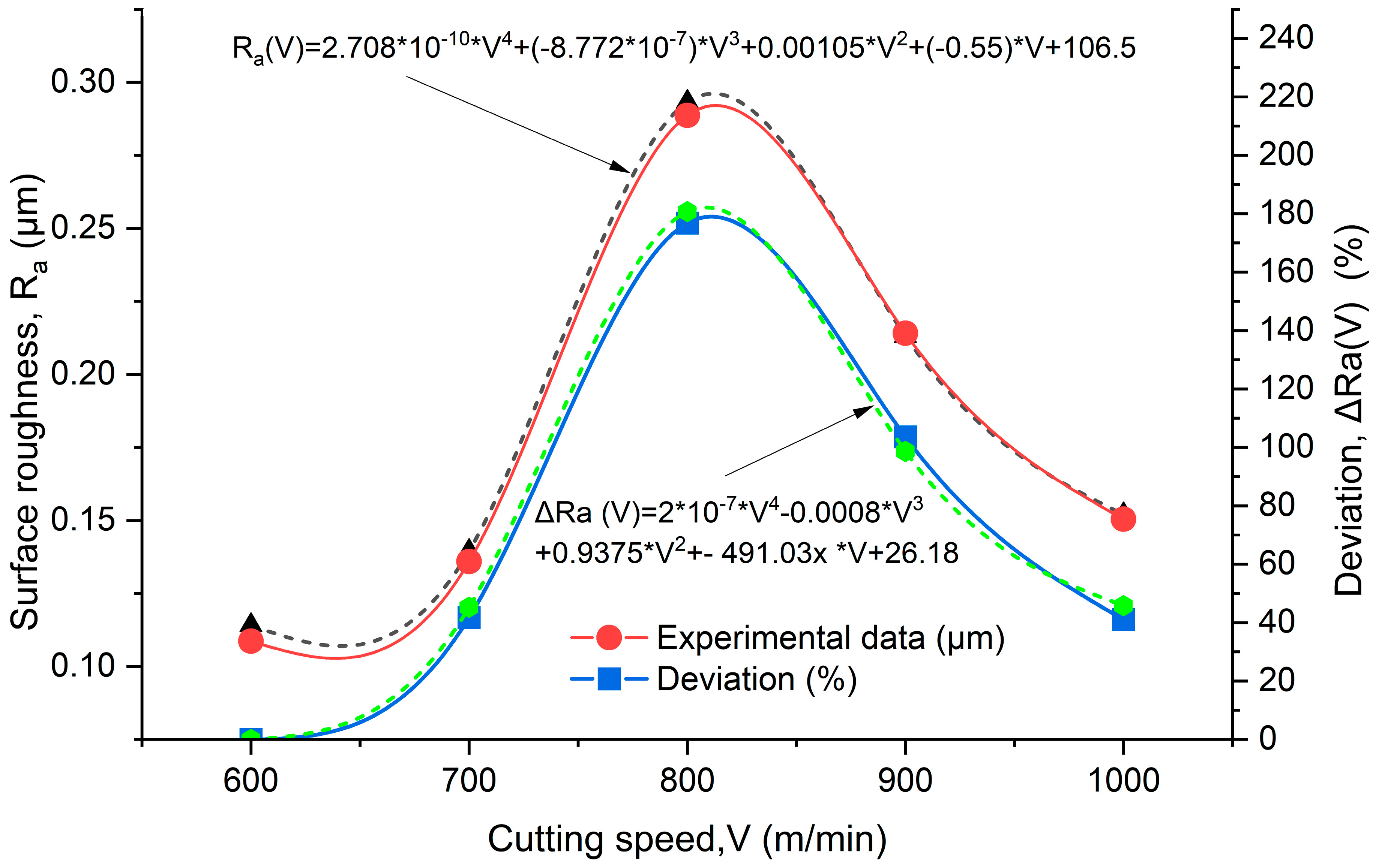
To evaluate the effect of high-speed cutting on surface roughness during milling in a TAM environment, experiments were conducted with a fixed feed rate (f = 802 mm/min), a fixed depth of cut (t = 1.5 mm), and a fixed workpiece heating temperature (T = 500 °C). The cutting speed was increased from 600 m/min to 1000 m/min. The percentage deviations of the surface roughness when machining at various cutting speeds (ΔRaV) are calculated by Formula (5). The surface roughness results at different settings are presented in Table 5 and Figure 10. The results show that when the cutting speed is increased from 600 to 800 m/min, the surface roughness increases significantly. However, when the cutting speed continues to increase from 800 to 1000 m/min, the surface roughness decreases.
Δ R a V % = R a V R a 600 R a 600 × 100
where Ra600 and RaV are corresponding to the surface roughness when machining at a cutting speed of 600 m/min and various cutting speeds.

3.4. Relationship between Surface Roughness and Cutting-Tool Wear during High-Speed Machining and TAM Process for SKD11 Steel

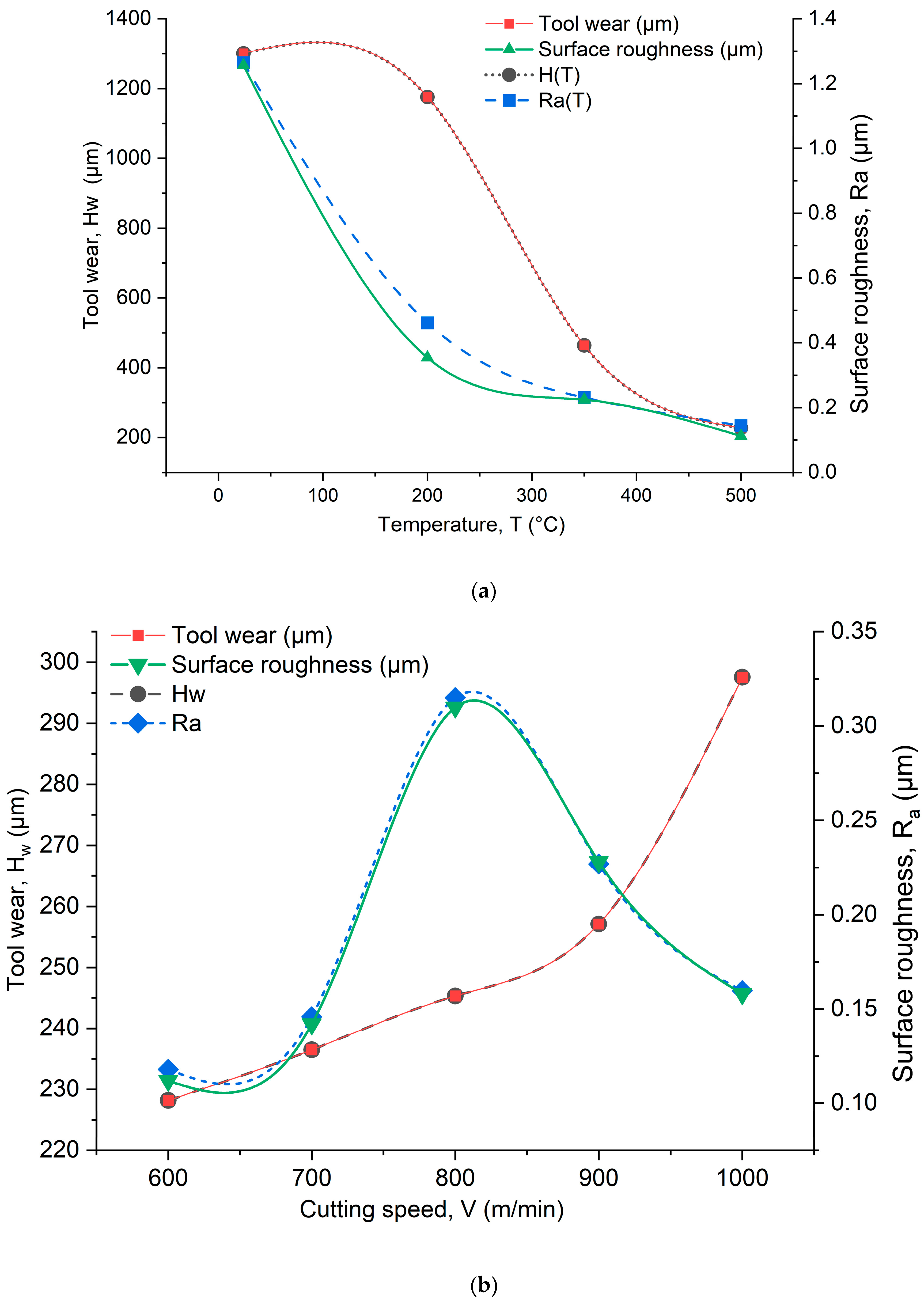
This section establishes the relationship between roughness and tool wear during high-speed machining with heating support for SKD11 steel based on the relationship between TAM, high-speed cutting, roughness, and tool wear. Figure 11 shows the effect of temperature and cutting speed on tool wear and surface roughness. As the temperature increases, tool wear decreases, and surface roughness tends to decrease (Figure 11a). Thus, at a constant cutting speed, the amount of tool wear is greatly reduced as the temperature is increased from 24 to 200, 350, and 500 °C, leading to a large decrease in surface roughness. Meanwhile, increasing the cutting speed from 600 to 700 and 800 m/min leads to an insignificant increase in tool wear, resulting in an increase in surface roughness. However, at higher cutting speeds above 800 m/min, the effect of speed on roughness is greater than that of the tool-wear rate. During high-speed machining, the cutting speed increases, and the higher workpiece temperature weakens the bond between metal particles. The increased temperature at the machining point also softens the workpiece, limiting the possibility of microcracks caused by adjoining existing porosities in the workpiece. Additionally, during machining at higher speeds, the tool’s cutting edge is polished and sharpened, resulting in better surface quality.
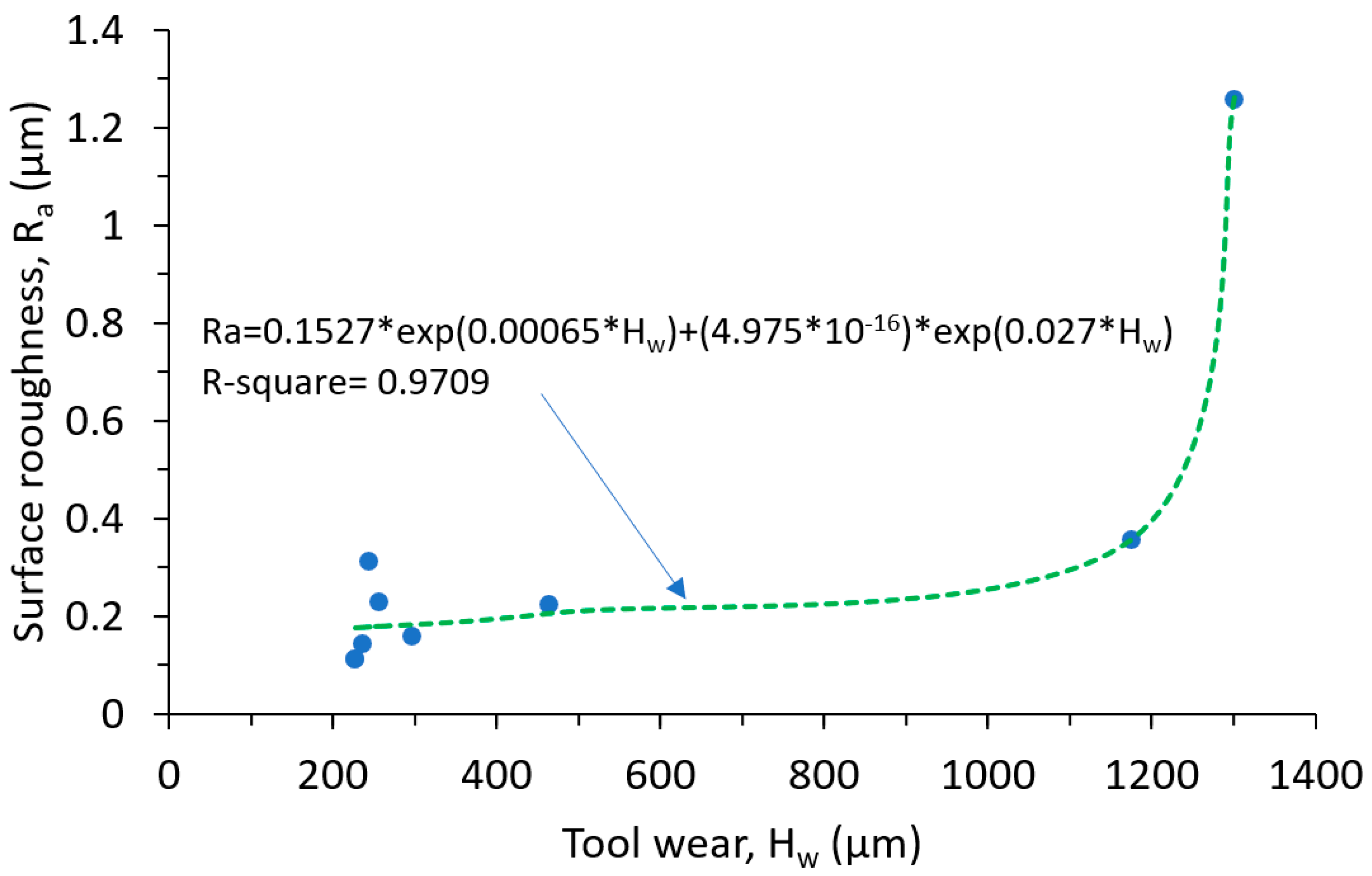
Through an analysis of the relationship between tool wear and surface roughness in high-speed machining and TAM processes for SKD11 steel, Table 6 and Figure 12 were created to demonstrate the connection between surface roughness and cutting-tool wear during high-speed machining with heating support. Equation (6) accurately represents the relationship between surface roughness and wear height of the cutting tool, with an R-square value of 0.9709. As tool wear increases, surface roughness also increases. Severe tool wear is observed during high-speed cutting (V = 600 m/min) and machining at room temperature, with a tool-wear height of up to 1301.4 µm and product surface roughness of 1.256 µm. However, when the temperature is increased at this high-speed mode (V = 600 m/min), tool-wear height and surface roughness decrease sharply, reaching their minimum values at the T = 500 (°C) TAM mode. This represents an improvement of 82.47% and 91.08% in tool wear and surface roughness, respectively, compared to machining at room temperature. When the cutting speed is increased at the heating mode T = 500 (°C), the amount of tool wear tends to increase, reaching a decrease in wear of 77.14% at V = 1000 m/min. Surface roughness is significantly improved, with an 87.42% increase in roughness compared to machining at room temperature and high speed (V = 600 m/min).
R a = 0.1527 × exp 0.00065 × H w + 4.975 × 10 16 × exp 0.027 × H w
where: Ra refers to surface roughness measured in micrometers (µm), and Hw represents the tool-wear height, also measured in micrometers (µm).
The present study investigated the effect of temperature and high-speed cutting on tool wear and surface roughness during high-speed milling of SKD11 steel in a TAM environment induced by electromagnetic induction. The results provide valuable insights for selecting appropriate heating conditions, high-speed cutting modes, and other parameters. Specifically, if the objective is to achieve a desired surface quality, a heating temperature of 500 °C and a cutting speed of 600 m/min can result in low surface roughness. However, if the focus is on increasing the material-removal rate, a cutting speed of 1000 m/min and a tempering temperature of 500 °C are recommended while still achieving low surface roughness in the high-temperature condition. These findings can contribute to the optimization of the machining process for improved efficiency and performance. Furthermore, the approach of using electromagnetic induction for heating during high-speed milling presents a promising alternative for enhancing the machinability of SKD11 steel.

4. Conclusions

In this experimental study, we investigated the impact of high temperature and cutting speed on cutting-tool wear and surface roughness during high-speed milling of SKD11 alloy steel in a TAM environment. This study yielded the following significant conclusions:
-
The heating process is an effective and economical method for supporting milling with low-cost non-carbide-coated cutting tools.
-
Tool wear decreases as TAM temperature increases during the machining process, and increases with increasing cutting speed. Wear rates are relatively uniform between cutting speeds of 600 m/min to 900 m/min, with faster wear rates observed at speeds greater than 900 m/min.
-
Surface roughness decreases with increasing TAM temperature during the milling process. The roughness initially increases with increasing cutting speed between 600 m/min and 800 m/min but decreases as the cutting speed continues to increase.
-
The amount of wear height has a clear impact on surface roughness during high-speed machining with a TAM of SKD11 steel. However, when the cutting speed exceeds 800 m/min, the effect of cutting speed on surface roughness becomes more pronounced than the impact of tool wear under the same TAM temperature of 500 °C, even though the tool wear rate increases significantly at high cutting speeds.
-
To achieve optimal surface quality, we recommend using a milling mode with a cutting speed of 600 m/min at 500 °C. However, for higher material removal speed and reduced machining time, a cutting speed of 1000 m/min and a TAM temperature of 500 °C are ideal, while still achieving low surface roughness under these conditions.
In conclusion, this study provides valuable insights into the effects of elevated temperature and high-speed cutting on cutting-tool wear and surface roughness during high-speed milling with TAM of SKD11 alloy steel. The findings can guide the selection of suitable machining conditions for achieving the desired surface quality and material-removal rate while minimizing tool wear.

Author Contributions

Conceptualization, D.-T.N.; Data curation, T.-B.M.; Formal analysis, D.-T.N.; Funding acquisition, T.-T.L.; Investigation, T.-T.L.; Methodology, D.-T.N.; Project administration, T.-B.M.; Resources, T.-B.M.; Software, T.-T.L.; Supervision, D.-T.N.; Validation, D.-T.N.; Visualization, D.-T.N.; Writing—original draft, T.-B.M.; Writing—review & editing, D.-T.N. and T.-B.M. All authors have read and agreed to the published version of the manuscript.

Funding

This work was supported by Vietnam Ministry of Education and Training (MOET) under grant number B2022-BKA-08.

Data Availability Statement

Not applicable.

Acknowledgments

The authors gratefully thank the financial support of Vietnam Ministry of Education and Training under Vietnam Grants B2022-BKA-08. The School of Mechanical Engineering and Hanoi University of Science and Technology are gratefully acknowledged for providing the support and conditions to carry out this research.

Conflicts of Interest

The authors declare no conflict of interest.

References

  1. Liu, Z.; Ai, X.; Zhang, H.; Wang, Z.; Wan, Y. Wear patterns and mechanisms of cutting tools in high-speed face milling. J. Mater. Process. Technol. 2002, 129, 222–226. [Google Scholar] [CrossRef]
  2. Khan, S.A.; Ameer, M.F.; Uddin, G.M.; Ali, M.A.; Anwar, S.; Farooq, M.U.; Alfaify, A. An in-depth analysis of tool wear mechanisms and surface integrity during high-speed hard turning of AISI D2 steel via novel inserts. Int. J. Adv. Manuf. Technol. 2022, 122, 4013–4028. [Google Scholar] [CrossRef]
  3. Baig, A.; Jaffery, S.H.I.; Khan, M.A.; Alruqi, M. Statistical Analysis of Surface Roughness, Burr Formation and Tool Wear in High Speed Micro Milling of Inconel 600 Alloy under Cryogenic, Wet and Dry Conditions. Micromachines 2023, 14, 13. [Google Scholar] [CrossRef] [PubMed]
  4. Thi-Hoa, P.; Thi-Bich, M.; Van-Canh, T.; Tien-Long, B.; Duc-Toan, N. A study on the cutting force and chip shrinkage coefficient in high-speed milling of A6061 aluminum alloy. Int. J. Adv. Manuf. Technol. 2018, 98, 177–188. [Google Scholar] [CrossRef]
  5. del Olmo, A.; de Lacalle, L.L.; de Pissón, G.M.; Pérez-Salinas, C.; Ealo, J.; Sastoque, L.; Fernandes, M. Tool wear monitoring of high-speed broaching process with carbide tools to reduce production errors. Mech. Syst. Signal Process. 2022, 172, 109003. [Google Scholar] [CrossRef]
  6. Lezanski, P.; Shaw, M.C. Tool face temperatures in high speed milling. J. Eng. Ind. 1990, 112, 132–135. [Google Scholar] [CrossRef]
  7. Tian, X.; Zhao, J.; Zhao, J.; Gong, Z.; Dong, Y. Effect of cutting speed on cutting forces and wear mechanisms in high-speed face milling of Inconel 718 with Sialon ceramic tools. Int. J. Adv. Manuf. Technol. 2013, 69, 2669–2678. [Google Scholar] [CrossRef]
  8. Irving, A.D.; Clarance, L.M.; Russell, F.H. High Temperature Machining Methods; Armed Services Techinical Information Agency, Arlington Hall Station: Arlington, VA, USA, 1963. [Google Scholar]
  9. Su, H.; Liu, P.; Fu, Y.; Xu, J. Tool life and surface integrity in high-speed milling of titanium alloy TA15 with PCD/PCBN tools. Chin. J. Aeronaut. 2012, 25, 784–790. [Google Scholar] [CrossRef]
  10. Mac, T.-B.; Luyen, T.-T.; Nguyen, D.-T. A Study for Improved Prediction of the Cutting Force and Chip Shrinkage Coefficient during the SKD11 Alloy Steel Milling. Machines 2022, 10, 229. [Google Scholar] [CrossRef]
  11. Kong, X.; Dang, Z.; Liu, X.; Wang, M.; Hou, N. Simulation and Experimental Analysis of Tool Wear and Surface Roughness in Laser Assisted Machining of Titanium Alloy. Crystals 2023, 13, 40. [Google Scholar] [CrossRef]
  12. Jeong, H.-I.; Lee, C.-M. A study on improvement of tool life using a heat shield in laser assisted machining to Inconel 718. Opt. Laser Technol. 2021, 142, 107208. [Google Scholar] [CrossRef]
  13. Xavierarockiaraj, S.; Kuppan, P. Investigation of cutting forces, surface roughness and tool wear during laser assisted machining of SKD11Tool steel. Procedia Eng. 2014, 97, 1657–1666. [Google Scholar] [CrossRef]
  14. Thanh-Huan, N.; Duc-Toan, N. Experimental Researches of Turning Hardened 9CrSi Alloy Tool Steel with Laser-Assisted Machining. Arab. J. Sci. Eng. 2021, 46, 11725–11738. [Google Scholar] [CrossRef]
  15. Bijanzad, A.; Munir, T.; Abdulhamid, F. Heat-assisted machining of superalloys: A review. Int. J. Adv. Manuf. Technol. 2022, 118, 3531–3557. [Google Scholar] [CrossRef]
  16. Phan, N.H.; Toan, N.D.; Shailesh, S. Simultaneous improvement of Z-coordinate and overcut in EDM of titanium grade 5 alloy using a carbon-coated micro-tool electrode. Mod. Phys. Lett. B 2023, 2340004. [Google Scholar] [CrossRef]
  17. Özler, L.; Inan, A.; Özel, C. Theoretical and experimental determination of tool life in hot machining of austenitic manganese steel. Int. J. Mach. Tools Manuf. 2001, 41, 163–172. [Google Scholar] [CrossRef]
  18. Ginta, T.L.; Amin, A.N. Thermally-assisted end milling of titanium alloy Ti-6Al-4V using induction heating. Int. J. Mach. Mach. Mater. 2013, 14, 194–212. [Google Scholar] [CrossRef]
  19. Chang, C.-W.; Kuo, C.-P. Evaluation of surface roughness in laser-assisted machining of aluminum oxide ceramics with Taguchi method. Int. J. Mach. Tools Manuf. 2007, 47, 141–147. [Google Scholar] [CrossRef]
  20. Wang, R.; Yang, D.; Wang, W.; Wei, F.; Lu, Y.; Li, Y. Tool Wear in Nickel-Based Superalloy Machining: An Overview. Processes 2022, 10, 2380. [Google Scholar] [CrossRef]
  21. Ye, G.; Zhang, P.; Zhang, J.; Zhang, Y.; Huang, X. Study on nanometer cutting mechanism of single crystal silicon at different temperatures. J. Manuf. Process. 2023, 93, 275–286. [Google Scholar] [CrossRef]
  22. Germain, G.; Santo, P.D.; Lebrun, J. Comprehension of chip formation in laser assisted machining. Int. J. Mach. Tools Manuf. 2011, 51, 230–238. [Google Scholar] [CrossRef]
  23. Mac, T.-B.; Banh, T.-L.; Nguyen, D.-T. Study on cutting force and chip shrinkage coefficient during thermal: Assisted machining by induction heating of SKD11 steel. J. Korean Soc. Precis. Eng. 2019, 36, 803–811. [Google Scholar] [CrossRef]
  24. Mac, T.B.; Luyen, T.T.; Nguyen, D.T. Assessment of the Effect of Thermal-Assisted Machining on the Machinability of SKD11 Alloy Steel. Metals 2023, 13, 699. [Google Scholar] [CrossRef]
  25. Musavi, S.H.; Sepehrikia, M.; Davoodi, B.; Niknam, S.A. Performance analysis of developed micro-textured cutting tool in machining aluminum alloy 7075-T6: Assessment of tool wear and surface roughness. Int. J. Adv. Manuf. Technol. 2022, 119, 3343–3362. [Google Scholar] [CrossRef]
  26. Sommer, D.; Pape, D.; Esen, C.; Hellmann, R. Tool Wear and Milling Characteristics for Hybrid Additive Manufacturing Combining Laser Powder Bed Fusion and In Situ High-Speed Milling. Materials 2022, 15, 1236. [Google Scholar] [CrossRef]
  27. Ghoreishi, R.; Roohi, A.H.; Ghadikolaei, A.D. Analysis of the influence of cutting parameters on surface roughness and cutting forces in high speed face milling of Al/SiC MMC. Mater. Res. Express 2018, 5, 086521. [Google Scholar] [CrossRef]
  28. Dong, T.P.; Toan, N.D. A study on the investigation of the microstructure of SKD61 steel after selected quenching and tempering processes. Mod. Phys. Lett. B 2023, 2340022. [Google Scholar] [CrossRef]
  29. Subramanian, A.V.M.; Nachimuthu, M.D.G.; Cinnasamy, V. Assessment of cutting force and surface roughness in LM6/SiC p using response surface methodology. J. Appl. Res. Technol. 2017, 15, 283–296. [Google Scholar] [CrossRef]
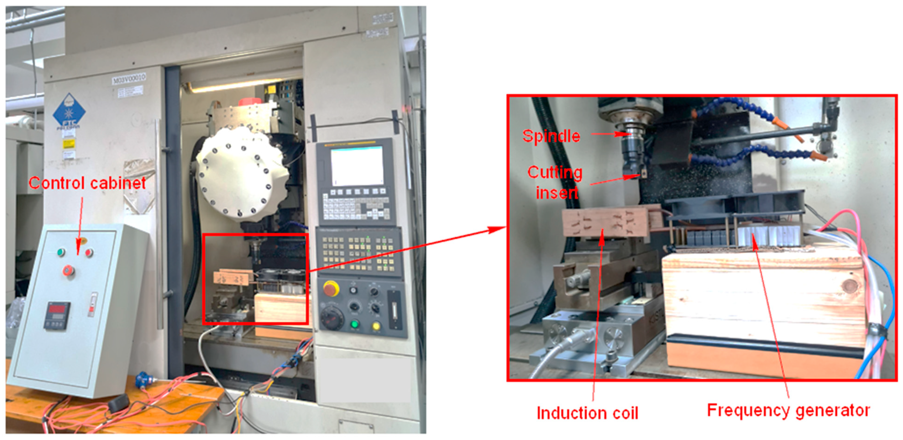
Figure 1. Experimental setup for the milling process.
Metals 13 00971 g001
Figure 2. Testing equipment. (a) Microbalance AJ-3002 from Vibra-Japan, (b) HD-30AX series high-precision digital microscope.
Metals 13 00971 g002
Figure 3. Tool-wear changes of uncoated hard-alloy cutting tool during SKD11 steel milling at different temperatures—room temperature (a), 200 °C (b), and 500 °C (c).
Metals 13 00971 g003aMetals 13 00971 g003b
Figure 4. The tool wear and corresponding wear reduction measured by weight (a) and height (b) during milling at various temperatures.
Metals 13 00971 g004
Figure 5. Tool wear during high-speed milling with a TAM of 500 °C at V = 1000 m/min (a) and V = 1100 m/min (b).
Metals 13 00971 g005
Figure 6. The variation of tool-wear height at different cutting speeds and TAM of 500 °C.
Metals 13 00971 g006
Figure 7. The measurement method and the results of the surface roughness profile.
Metals 13 00971 g007
Figure 8. The surface roughness profile obtained under different machining temperatures: room temperature (a), 200 °C (b), 350 °C (c), and 500 °C (d).
Metals 13 00971 g008aMetals 13 00971 g008b
Figure 9. The impact of temperature at a cutting speed of 600 (m/min) on the surface roughness of SKD11 steel during milling.
Metals 13 00971 g009
Figure 10. The surface roughness obtained at various high-speed cutting rates with a TAM of 500 °C.
Metals 13 00971 g010
Figure 11. Effect of cutting temperature (a) and cutting speed (b) on tool wear and surface roughness.
Metals 13 00971 g011
Figure 12. Relationship between roughness and tool wear during high-speed machining with heating support for SKD11 steel.
Metals 13 00971 g012
Table 1. Chemical composition of SKD11 alloy steel, mass %.
CCrMoSiMnPSV
1.4211.70.830.30.410.0250.00040.23
Table 2. Cutting conditions and measured tool-wear height results at various temperatures.
Exp. No.V
(m/min)
f
(mm/min)
t
(mm)
T
(°C)
mw
(g)
Hw
(µm)
Δmw-T (%)ΔHw-T
(%)
16008021.5240.0471301.4--
26008021.52000.0071176.085.119.64
36008021.53500.002464.295.7464.33
46008021.55000.002228.295.7482.47
Table 3. Cutting conditions and measured tool-wear height results at various high-speed milling.
Exp. No.V
(m/min)
f
(mm/min)
t
(mm)
T
(°C)
Hw
(µm)
ΔHw
(%)
16008021.5500228.20
27008021.5500236.53.6
38008021.5500245.37.5
49008021.5500257.112.7
510008021.5500297.530.4
Table 4. The surface roughness outcomes obtained during the high-speed milling process at elevated temperatures.
Exp. No.V
(m/min)
f
(mm/min)
t
(mm)
T
(°C)
Ra
(µm)
ΔRa (%)
16008021.5241.256-
26008021.52000.35471.82
36008021.53500.22482.17
46008021.55000.11291.08
Table 5. The surface roughness outcomes obtained during the high-speed milling process at different cutting speeds and a TAM of 500 °C.
Exp. No.V
(m/min)
f
(mm/min)
t
(mm)
T
(°C)
Ra
(µm)
ΔRa
(%)
156008021.55000.112-
167008021.55000.14226.79
178008021.55000.31176.79
189008021.55000.228103.57
1910008021.55000.15841.07
Table 6. The tool-wear height and surface roughness results obtained from high-speed milling at various temperature conditions.
V (m/min)6006006006007008009001000
T (°C)24200350500500500500500
Hw (µm)1301.41176464.2228.2236.5245.3257.1297.5
Ra (µm)1.2560.3540.2240.1120.1420.310.2280.158
ΔHw % -9.6464.3382.4781.8381.1580.2477.14
ΔRa % -71.8282.1791.0888.6975.3281.8587.42
Disclaimer/Publisher’s Note: The statements, opinions and data contained in all publications are solely those of the individual author(s) and contributor(s) and not of MDPI and/or the editor(s). MDPI and/or the editor(s) disclaim responsibility for any injury to people or property resulting from any ideas, methods, instructions or products referred to in the content.