Abstract
Novel HEAp-Ti/Al laminated composites embedded with particles of the high-entropy alloy Al0.5CoCrFeNi (HEA) were fabricated by vacuum hot-press sintering at 730 °C. The phase composition and microstructure of the composites were studied with X-ray diffractometer (XRD), scanning electron microscope SEM, energy dispersive spectrometer (EDS), transmission electron microscope (TEM), and electron backscattering diffraction (EBSD) techniques. At this temperature, it has been observed that Al3Ti intermetallic compound is the favored phase and the reaction results in the dispersion of Al3Ti in the original Al layer. A large number of interfaces are formed between Al3Ti and Al. The deformed Al3Ti grains are concentrated in the interface near the Ti side. The mechanical properties, including tensile and compressive properties at room temperature, were analyzed. The tensile test results indicate that the composite exhibited an average tensile strength of 258 MPa and an average yield strain of 9.86%. Compression test results show that when a load perpendicular to the layer is applied, the yield strain and yield stress of the material are 9.67% and 474.09 MPa, respectively. Moreover, under a load parallel to the layer, the material fails due to interfacial debonding.
1. Introduction
Metal–intermetallic laminated (MIL) composites have gained significant attention due to their excellent mechanical properties [1]. These composites are prepared using various intermetallic compound systems such as Fe-Al [2], Ti-Al [3], and Ni-Al [4]. Among these systems, Ti-Al3Ti MIL composites exhibit low density, high modulus of elasticity, and exceptional high-temperature properties, making them promising materials for high-temperature-resistant structural applications [5,6,7,8]. In 2001, Vecchio [9] created MIL-layered composites using Ti-Al plates stacked on top of each other in an air environment and reacted through sintering. This process maintained a continuous reaction interface between solid Ti and liquid Al, which controlled the growth of Al3Ti. In a follow-up study, the researchers investigated the phases that formed after the Ti-Al diffusion reaction. By comparing the Gibbs free energy of the Ti-Al family of intermetallic compounds, they found that only Al3Ti was produced. This conclusion was also supported by Mostafa’s study [10,11].
To study the mechanical properties of MIL composites, various testing methods have been employed by scholars. Rohatgi et al. [12] conducted a study on Ti-Al3Ti laminated composites where the R-curves and fracture behavior were investigated by testing single-sided notched specimens. The fracture toughness of MIL composites was observed to increase by more than ten times compared to monolithic Al3Ti. This was attributed to the plastic deformation of the Ti layers, which resulted in energy dissipation and the consequent increase in fracture toughness values. Adharapurapu et al. [13] investigated the fatigue crack extension in MIL composites, which indicated that the toughness of the composites is improved by both crack capture at the ductile/brittle interface and subsequent crack bridging formed by the ductile Ti layer. In addition, some fiber and particle reinforcements were introduced into the MIL composites to further improve the material properties. Jiang et al. [14] prepared a shape memory alloy NiTi fiber reinforced (SMAFR) Ti/Al3Ti laminated composite, whose ductility was enhanced greatly due to the introduction of superelastic NiTi fiber. It is noteworthy that a named reactive band between the NiTi fiber and the matrix formed during the fabrication process, which possessed the ability to transfer the load from the matrix to the fiber reinforcement. SiC and Al2O3 ceramic fibers were incorporated into Ti/Al3Ti laminate composites, and the results demonstrated that the fibers enhance the toughness of the composite by promoting fiber debonding and pull-out effects [15,16].
In recent years, high-entropy alloys (HEAs) have gained comprehensive attention due to their superior performance [17,18,19]. The presence of multiple principal elements in an alloy results in an increase in the overall mixed entropy, leading to the formation of simple solid solutions like FCC, BCC, and HCP [20]. It has been found that the HEA particle reinforcement exhibits exceptional wettability with the matrix, resulting in superior interfacial bonding [21,22]. As a result, HEA particles are considered an ideal choice for use as reinforcements in structural composites. Due to the severe lattice distortion effect, high-entropy alloys (HEAs) exhibit excellent physical properties such as high hardness and strength, making them ideal for various applications in fields like aerospace and nuclear engineering [23]. Among the various HEA systems, the AlxCoCrFeNi system has been studied extensively for its mechanical properties and phase composition [24,25,26,27]. The Al0.5CoCrFeNi high-entropy alloy differs from the equal atomic ratio AlCoCrFeNi high-entropy alloy in that it is composed of both a ductile FCC phase and a brittle BCC phase [28,29]. This unique phase structure contributes to improved mechanical properties. Al0.5CoCrFeNi high-entropy alloy has shown potential in particle reinforcement applications. In a study conducted by Li et al. [30], it was demonstrated that the inclusion of Al0.5CoCrFeNi high-entropy alloy particles led to a considerable reduction in grain size within the 2024Al matrix. Zhang et al. [31] used ultrasonic casting to prepare Al0.5CoCrFeNi high-entropy alloy particle-reinforced Al matrix composites. The addition of the high-entropy alloy particles resulted in a significant reduction in the grain size of the Al matrix, which in turn increased the number of grain boundaries. This large number of grain boundaries hindered dislocation movement during the tensile process, thus increasing the yield limit of the composite. In general, the incorporation of Al0.5CoCrFeNi high-entropy alloy can enhance matrix properties.
Despite the growing interest in HEA particles, limited research has been conducted on their impact on the microstructure and mechanical properties of multilayered composites. Additionally, the failure mode of these composites remains unknown. To address this gap in knowledge, we investigated the effect of Al0.5CoCrFeNi high-entropy alloy particles on the mechanical properties of MIL composites. HEA particle-reinforced MIL composites were prepared through vacuum hot-press sintering. The study investigated the phase composition of HEAp-Ti/Al laminated composites through various techniques such as XRD, SEM, EDS, TEM, and EBSD. The tensile properties were also examined through static tensile experiments at room temperature, and the failure mechanism was determined by observing tensile fractures. Moreover, the compressive properties were evaluated by conducting compression tests with varying loading directions, and the failure mechanism was discussed in detail.
2. Experimental Procedure
2.1. Materials Preparation
HEAp-Ti/Al laminated composites were prepared by vacuum hot-press sintering of TA1 foil (80 mm × 80 mm × 0.8 mm), 1060Al foil (80 mm × 80 mm × 0.9 mm), and HEA particles (2 g). HEA particles were purchased from Beijing Yijin New Material Technology Co., Ltd., Beijing, China. The compositions of the two foil materials used are shown in Table 1. Before carrying out vacuum hot-press sintering, the oil and oxide films on the surfaces of the TA1 foil and Al foil were treated to provide a good surface condition for the subsequent preparation of the materials.

Table 1.
The chemical compositions of foils and HEA Particles in the composite.
The treated materials were stacked according to the sequence of Ti-Al-HEAp-Al-Ti, and then the stacked materials were put into a vacuum hot-pressing furnace for sintering (High Multi5000, Jiamusi, China). In the preparation process, firstly, the temperature was raised to 600 °C at the heating rate of 6.67 °C/min, and the pressure of 3 MPa was applied. A heating rate of 6.67 °C/min ensures that the foil is heated uniformly. The application of a pressure of 3 MPa ensures that the softer Al does not suffer large plastic deformations under high pressure and that a good mechanical bond between the softened TA1 foil and the aluminum foil can be achieved. Then, the temperature was kept at 600 °C for 30 min, and then the temperature was raised to 730 °C at a heating rate of 4.33 °C/min, and the pressure was removed after reaching the set temperature. After holding at 730 °C for 6 h, the pressure of 3 MPa was re-applied. Once the furnace temperature dropped to 400 °C, the pressure was removed. Finally, the sample was cooled to room temperature together with the vacuum hot pressing furnace. The schematic diagram of the treatment process of the original material and the preparation process of the HEAp-Ti/Al laminated composite is shown in Figure 1.
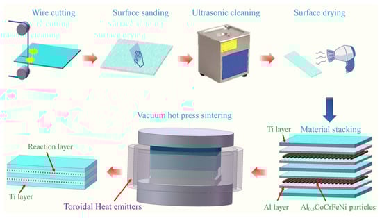
Figure 1.
Schematic diagram of raw material treatment method and preparation process of HEAp-Ti/Al laminated composites.
2.2. Microstructure Characterization
An X’Pert PRO X-ray diffractometer (Harbin, China) was used to determine the phase composition of HEAp-Ti/Al laminated composites. The scanning range was from 20° to 90°, and the scanning speed was 4°/min. The microstructure of the prepared materials was characterized using a scanning electron microscope (SEM) of ZEISS sigma500 (Wuhan, China) and FEI Nova NanoSEM450 (Zhengzhou, China), and the element distribution and atomic ratio of the prepared materials were identified with an energy dispersive spectrometer (Harbin, China). The reaction layer was observed with a JEM-2100 transmission electron microscope (Harbin, China). The data collected by electron backscattering diffraction (EBSD) were analyzed using OIM software (OIM 6.0, Ametek Inc., Berwyn, PA, USA).
2.3. Mechanical Testing Methods
The quasi-static tensile and compressive properties of laminated composites were tested on an Instron universal testing machine (Instron 5967, Nantong, China). The strain rates of tensile and compressive tests were both 10−3/s. Due to the anisotropy of the properties of laminated composites, loads are applied in two directions perpendicular to and parallel to the laminates during the compression test. After the test is completed, the engineering stress–strain curve is drawn by engineering stress and engineering strain. The size of the specimen for the mechanical properties test is shown in the corresponding section.
3. Results and Discussion
3.1. Morphologies of HEA Particles and XRD Patterns
As shown in Figure 2a, the Al0.5CoCrFeNi particles display a spherical shape with an average size of approximately 320 μm. Compared to smaller particles, using high-entropy alloy (HEA) particles of this size can enhance the contact area between the particles and the matrix, promoting superior interfacial bonding. The EDS mapping images and the atomic ratios between the elements are shown in Figure 3b–f, where the elements are evenly distributed and no elemental aggregation occurs.
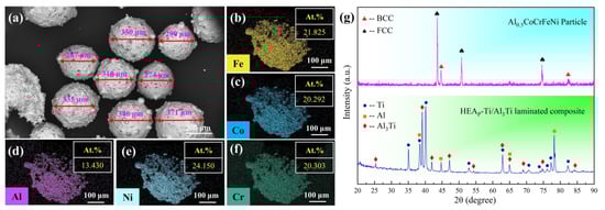
Figure 2.
(a) SEM image of Al0. 5CoCrFeNi particles; (b–f) EDS element mapping images; (g) XRD patterns of HEA particles and HEAp-Ti/Al laminated composites.
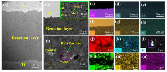
Figure 3.
Microstructure of HEAp-Ti/Al laminated composites: (a) SEM image containing the Ti layer and reaction layer; (b) SEM image of the Ti layer and reaction layer; (c–h) EDS mapping of different elements corresponding to (b); (i) SEM image of the reaction layer containing HEA particles; (j–o) EDS mapping of different elements corresponding to (i).
Figure 2g depicts the XRD patterns of HEA particles and HEAp-Ti/Al laminated composites. The figure reveals that the Al0.5CoCrFeNi particles utilized in the experiment consist of both body-centered cubic (BCC) and face-centered cubic (FCC) phases, with no other hybrid phases present. The laminated composites, prepared at 730 °C, consist of Ti phase, Al phase, and Al3Ti phase, indicating the presence of residual Al phase in the composites.
3.2. SEM Morphologies
As shown in Figure 3a, HEAp-Ti/Al laminated composites comprise a Ti layer and a reaction layer. Figure 3c–h demonstrates that the elements are evenly distributed near the interface. While some particles were consumed during the diffusion process, residual HEA particles were found in the middle of the reaction layer, as shown in Figure 3i. Based on the results of the point energy spectra at points 4 and 5, it is clear that the phases surrounding the HEA particles are the Al phase and the Al3Ti phase, respectively. It is widely recognized that the majority of Ti/Al laminated composites have a center line in the original Al layer (or Al3Ti layer, reaction layer, etc.). However, the residual HEA particles are observed to partially bridge the aforementioned defects. Upon analysis of Table 2 and Figure 3j–o, it becomes apparent that the Fe element displays significant variations in comparison to the other elements. The EDS surface scan further confirms the aggregation of Fe at this location.
Table 2.
Elemental and corresponding atomic ratios for each point.
3.3. TEM Results
According to the Ti-Al phase diagram in Figure 4a, when the temperature is increased, intermetallic compounds such as Ti3Al, TiAl, TiAl2, and Ti2Al5 may appear in addition to Al3Ti formation. In order to further determine the composition of the phases in the reaction layer, a TEM analysis of the reaction layer was carried out. Figure 4b displays a clear interface, while Figure 4c,d shows the selected area electron diffraction SAED results for the regions near the interface, revealing the presence of the Al phase and Al3Ti phase on each side of the interface. The results indicate that a strong interface bonding was formed between the residual aluminum and the newly formed Al3Ti, facilitating stress transfer and ultimately enhancing the material’s strength.
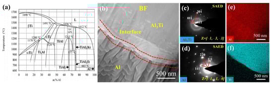
Figure 4.
TEM images of HEAp-Ti/Al laminated composites: (a) Ti-Al phase diagram; (b) bright field phases of Al3Ti and Ti; (c,d) selected area electron diffraction (SAED) of Al and Al3Ti, respectively; (e,f) EDS mapping of elements Al and Ti.
3.4. EBSD Characterization
The orientation and dynamic recrystallization of the grains have an important impact on the mechanical properties of the material and were, therefore, analyzed by EBSD. The image quality (IQ) map of HEAp-Ti/Al laminated composites is depicted in Figure 5a. It can be clearly seen that the grain size of the Ti layer is obviously larger than that of the reaction layer. Grains with different sizes can cause dislocation accumulation at the interface position, which leads to an improvement in work hardening ability, thus obtaining high strength and excellent plastic deformation ability. The phase map of HEAp-Ti/Al laminated composites is depicted in Figure 5b, with the reaction layer consisting of Al and Al3Ti phases. The ratio of the Al3Ti phase to the Al phase is approximately 0.424:0.192.
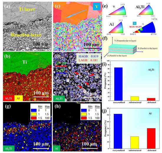
Figure 5.
EBSD analysis of HEAp-Ti/Al laminated composites: (a) IQ map of HEAp-Ti/Al laminated composites; (b) Phase distribution map of HEAp-Ti/Al laminated composites, green for Ti phase, yellow for Al phase, and red for Al3Ti phase; (c) IPF map of HEAp-Ti/Al laminated composites in the perpendicular to layer direction (Y); (d) Grain boundary map of Al3Ti, red—LAGB, blue—HAGB; (e) Color card of Ti, Al, and Al3Ti, and IPF map of Ti; (f) Orientation diagram for HEAp-Ti/Al laminated composites with the Y direction perpendicular to the layer; (g) Grain orientation spread map of Al3Ti; (h) Grain orientation spread map of Al; (i,j) Volume fraction statistics for recrystallization, substructure, and deformation regions of Al3Ti and Al, respectively.
Figure 5c shows the inverse pole figure (IPF) map of HEAp-Ti/Al laminated composites perpendicular to the layer. The Al and Al3Ti grains appear more dispersed in color and lack any noticeable preferred orientation. In contrast, the Ti grains are more concentrated in color and display a clear preferred orientation in the Y direction.
Figure 5d shows the grain boundary map of Al3Ti, where the percentage of high-angle grain boundaries (HAGB) is 0.819, and the percentage of low-angle grain boundaries (LAGB) is 0.181. In addition, some Al3Ti grains are separated by LAGB, indicating the occurrence of continuous dynamic recrystallization (CDRX). The temperature and pressure during material preparation also contribute to the promotion of CDRX. Therefore, it can be inferred that in HEAp-Ti/Al laminated composites, CDRX is the dominating recrystallization mechanism for Al3Ti.
The IPF map of Ti in Figure 5e confirms that Ti exhibits a texture//Y axis, with a maximum intensity of texture of 10.257. The texture of the material is determined by the direction of atom diffusion during preparation. Specifically, in layered materials, Ti atoms tend to move primarily perpendicular to the layers during the preparation process.
Figure 5g,h illustrates the distribution of recrystallized, substructured, and deformed regions for Al3Ti and Al, respectively. In these figures, blue represents the recrystallized grains, red represents the substructure, and yellow represents the deformation region. The percentage of recrystallized grains can be observed from Figure 5i,j, which are 0.832 for Al3Ti and 0.697 for Al. The percentage of deformed grains in Al is higher compared to that of Al3Ti. This can be attributed to the growth mechanism of Al3Ti. During formation, Al3Ti is ejected into the liquid Al, which then splits the liquid Al upon solidification, leading to the formation of numerous Al/Al3Ti interfaces. These interfaces result in tissue stresses during Al solidification, which can cause stress concentrations. When these stresses become too high, deformation of the Al grains can occur. It is worth noting that a large number of deformed Al3Ti grains appear at the interface location, and these grains have high internal stresses that can easily induce crack nucleation when subjected to external forces. However, it is also possible to transfer stresses quickly to the more plastic Ti layers, reducing the location of crack nucleation and thus improving the material’s properties.
In summary, it is clear from the results of the material characterization that no new phases were detected after the addition of the HEA particles. The EDS results show no agglomeration of the elements in the HEA in the material, and it can be assumed that the atoms of the elements are only solidly soluble in the lattice of Ti, Al3Ti, and Al. The effect of the HEA in bridging the centerline defects also has a beneficial effect on the properties of the material. The effect of HEA particles bridging the interface will be shown in the tensile fracture.
3.5. Tensile Testing
3.5.1. Macroscopic Fracture Morphology and Tensile Curves
Figure 6a displays the dimensions of the tensile specimen and the direction of loading during the tensile test. The image in Figure 6b shows the macroscopic view of the specimen after the tensile test, revealing that the reaction layer fractured earlier than the Ti layer. The engineering stress–strain curves of the HEAp-Ti/Al laminated composites are presented in Figure 6c. The average tensile strength reaches 258 MPa and an average yield strain of 9.86%. Moreover, it has an average elongation to failure of 49%. The HEAp-Ti/Al laminated composites first enter the elastic deformation stage, and after reaching the ultimate tensile strength, the stress drops rapidly. The fracture of the reaction layer is the main cause of the stress drop. The material then enters a necking phase until the material fractures, which is mainly loaded by the Ti layer.
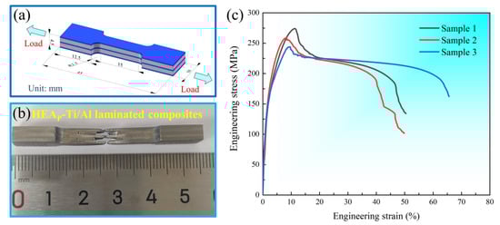
Figure 6.
Macroscopic fracture morphology and tensile curves: (a) Schematic diagram of tensile specimen size and loading direction; (b) Macroscopic morphology after tensile testing; (c) Engineering stress–strain curves.
3.5.2. Tensile Fracture Morphologies
Figure 7a depicts the macro picture of Figure 7b–d. The fracture surface in Figure 7b displays a significant height difference, suggesting that the fracture of the reaction layer occurred earlier than that of the Ti layer. Figure 7c,d showcases the fracture morphology on the side of the tensile specimen. The reaction layer exhibits transverse cracks (perpendicular to the layer) and longitudinal cracks (along the interface). Additionally, during the propagation process, there is a transverse crack deflection phenomenon, and a considerable number of Al phase tear traces appear in the fracture morphology. The plastic deformation of these Al phases during the tensile process can alleviate the internal stress, which ultimately improves the plastic deformation ability of the materials.
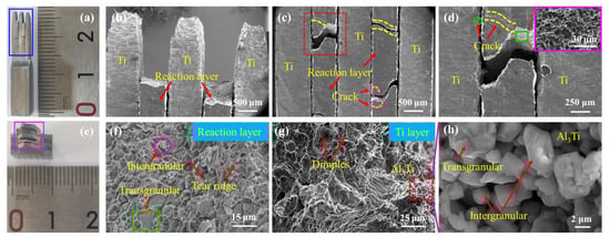
Figure 7.
Tensile fracture micromorphologies of HEAP-Ti/Al laminated composites: (a) SEM observation position of side surface of tensile specimen; (b) Side tensile fracture morphology, the reaction layer fractured earlier than Ti layer; (c) Reaction layers of interlaminar cracking and fracture; (d) An enlarged partial view corresponding to “(c)”; (e) SEM observation position of tensile specimen fracture; (f) The fracture characteristics of the reaction layer include brittle fracture of Al3Ti and plastic fracture of Al; (g) Plastic fracture characteristics of Ti layer and adhesion of Al3Ti; (h) The brittle fracture characteristics corresponding to the adhesion of Al3Ti in “(g)”.
Figure 7e shows the macro picture of Figure 7f–h. The fracture morphology of the reaction layer is shown in Figure 7f. The fracture surface of Al3Ti is flat, and there are some transgranular and transgranular fractures, which are typical brittle fracture characteristics. Moreover, there are a large number of tear cracks formed by the Al phase in the tensile process around it. Therefore, the reaction layer finally presents a mixed fracture mode of Al3Ti brittle fracture and Al plastic fracture. Figure 7g displays the fracture morphology of the Ti layer, revealing the presence of dimples, a typical feature of plastic fracture. Additionally, the Al3Ti phase is observed to adhere to one side of the fractured Ti layer. Figure 7h shows that the fracture mode of the Al3Ti is primarily intergranular, with a small amount of transgranular fracture. Notably, there is no tear crack of the Al phase in the fractured Al3Ti, indicating the formation of a dense Al3Ti layer at the interface.
Figure 8a,b displays the microscopic morphology of fractured HEA particles. The cracks are observed in the middle of the reaction layer due to the accumulation of oxides, which results in weak interfacial bonding. In Figure 8a, the HEA particles are penetrated by cracks, but there is no crack between the HEA particles and the matrix, indicating good interfacial bonding strength between them. This supports the feasibility of using HEA particles as reinforcement. In Figure 8b, the fracture surface of HEA particles is flat. Although EDS spot scanning results show that the proportion of Al atoms reaches 99.317%, HEA particles do not show the characteristics of plastic fracture but show the characteristics of brittle fracture.
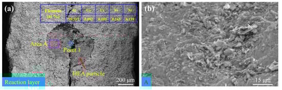
Figure 8.
Fracture morphologies of HEA particles: (a) Interlaminar cracks; (b) Fracture characteristics of HEA particles.
3.6. Compression Testing
3.6.1. Compression Results under Load Perpendicular to the Layer
Figure 9a illustrates the schematic diagram of the compression specimen for the HEAp-Ti/Al laminated composites, highlighting the specific dimensions and loading direction. The load was applied perpendicular to the layer direction during the compression test. Figure 9b presents the macroscopic morphology and engineering stress–strain curves of the compression pattern under this loading direction. The yield strain and yield stress of the material were 9.67% and 474.09 MPa, respectively, and did not undergo catastrophic crushing. As can be seen from Figure 9c, a large number of 45° shear cracks appear in the reaction layer during compression. It can be seen from Figure 9d that the fracture mode of the reaction layer is mainly transgranular fracture, and no tear ridge of the Al phase is found. Therefore, we can speculate that cracks mainly propagate along the location where Al3Ti is concentrated.
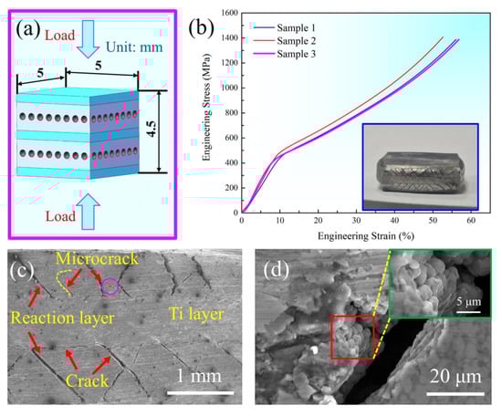
Figure 9.
Transverse compressive properties of HEAp-Ti/Al laminated composites: (a) The specific dimensions and loading direction; (b) Engineering stress-strain curves; (c) Cracks in the reaction layer; (d) The brittle fracture characteristics of the fracture surface.
3.6.2. Compression Results under Load Parallel to the Layer
A schematic diagram of the specific dimensions and loading directions of the HEAp-Ti/Al laminated composites compression specimen is shown in Figure 10a. It can be seen from the macroscopic morphology of the compressed sample in Figure 10b that debonding occurs at the interface between the reaction layer and the Ti layer, which is also the main failure mode of the prepared material at this temperature. The morphology of the side surfaces of the debonded reaction layer is shown in Figure 10c, producing a major crack of 45° and a number of tiny cracks. It can be seen from Figure 10d that there are a few plastic fracture characteristics of tearing ridges in the debonding surface, which are mainly transgranular fracture and intergranular fracture of intermetallic compound Al3Ti. Therefore, it is easier to induce crack nucleation at the interface position during deformation. When the deformation increases continuously, the crack propagates along the interface, which eventually leads to interface debonding.
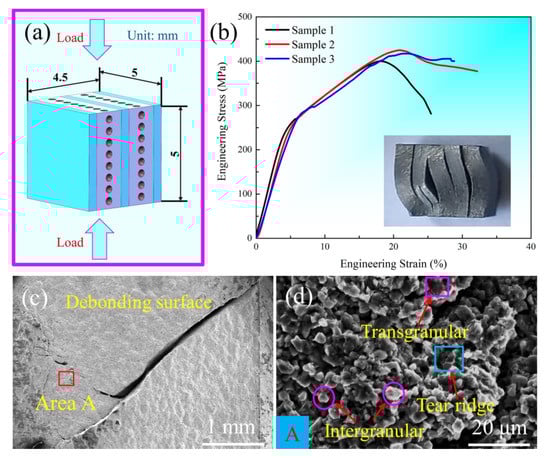
Figure 10.
Longitudinal compressive properties of HEAp-Ti/Al laminated composites: (a) The specific dimensions and loading direction; (b) Engineering stress–strain curves; (c) Cracks on the debonding surface of the reaction layer; (d) The brittle fracture characteristics of the debonding surface.
3.7. Strengthening Mechanism
Previous research has demonstrated that Ti/Al laminar composites possess exceptional mechanical properties [32,33,34]. By comparing Ti/Al laminate composites with known tensile properties, the composite produced in this study exhibits a certain degree of improvement in both strength and plasticity; the tensile properties of the relevant Ti/Al laminate composites are listed in Table 3. The following section will elucidate the mechanism behind this enhancement.
Table 3.
Tensile properties of Ti/Al laminate composites.
Through SEM, TEM, and EBSD characterization of the microstructure of the laminated composites, it can be found that the intermetallic compound Al3Ti formed in the preparation process is uniformly dispersed in the original Al layer in granular form, and a large number of interfaces are formed between Al3Ti and Al. At the same time, a certain number of HEA particles also exist in the reaction layer. The deformed grains of Al3Ti are concentrated at the interface of the reaction layer and Ti layer.
Figure 11a shows that the grain boundaries of Al and Al3Ti have high KAM values, indicating a higher dislocation density. The HRTEM image in Figure 11b reveals no lattice distortion in the Al3Ti lattice fringes at the interface locations. As shown in Figure 11c, a large number of dislocations are found to be present in the inverse fast Fourier transformation (IFFT) image near the interface location. The interfaces between Al and Al3Ti can lead to an increase in dislocation density, resulting in a significant number of dislocations at the interface location. This may impede each other’s motion during the material’s plastic deformation. The accumulation of dislocations due to the large number of grain boundaries during plastic deformation results in strain hardening, which improves the strength and plastic deformation ability of materials.
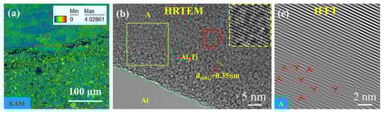
Figure 11.
(a) KAM map of HEAp-Ti/Al laminated composites; (b) HRTEM image of the interface location; (c) IFFT image of Al3Ti corresponding to (b).
When subjected to compressive stress perpendicular to the layer, Al with good plastic deformation ability will preferentially undergo plastic deformation, but a large number of interfaces in the reaction layer will hinder dislocation movement, so it is necessary to increase stress to promote dislocation movement, thus producing a strengthening effect. In HEAp-Ti/Al laminated composites, when Al3Ti particles come into contact with each other in the reaction layer, they bear the load and act as load strengtheners. As a result, a large number of tiny cracks form in the reaction layer and interlayer cracks at the interface between the reaction layer and the Ti layer. These cracks can absorb a significant amount of energy, thereby enhancing the material’s properties. In addition to this, analysis using SEM and tensile fracture shows that the HEA does not debond from the surrounding matrix during the tensile process and achieves good bridging action when delamination cracks occur in the reaction layer. It also acts as a barrier to dislocation movement during plastic deformation. The improvement in properties can be attributed to four main factors: (1) dislocation strengthening; (2) direct load-bearing capacity of Al3Ti; (3) multiple cracks that can absorb energy; and (4) HEA particles prevent dislocation movement.
4. Conclusions
Ti/Al laminate composites embedded with Al0.5CoCrFeNi particles were prepared by vacuum hot-press sintering at 730 °C. The microstructure and mechanical properties of the HEAp-Ti/Al laminated composites were investigated. The main conclusions drawn are as follows.
- The interfaces of HEAp-Ti/Al laminated composites exhibit strong bonding. Additionally, the intermetallic compound Al3Ti is evenly distributed throughout the original Al layer.
- TEM analysis revealed the presence of numerous dislocations at the interfacial region of the intermetallic compound Al3Ti and Al. Furthermore, EBSD analysis indicated the occurrence of Al3Ti deformation in the interface area between the Ti layer and the reaction layer.
- The results of the tensile test indicated that the HEAp-Ti/Al laminated composites had an average tensile strength of 258 MPa and an average yield strain of 9.86%. Upon observing the tensile fracture, it was observed that the Ti layer failed through plastic fracture, presenting dimples. On the other hand, the reaction layer exhibited both brittle and ductile fractures. The HEA particles showed brittle fracture characteristics.
- The results of the compressive test indicate that a significant number of microcracks are formed in the reaction layer when the load is applied perpendicular to the layer. This occurrence is advantageous in enhancing the material properties. When the load is applied parallel to the layer, material failure mainly occurs through interfacial debonding.
Author Contributions
Methodology, funding acquisition, writing—review & editing, E.W.; Writing—original draft, data curation, L.L.; Project administration, funding acquisition, F.K.; Resources, methodology, S.L.; Visualization, data curation, J.L.; Resources, investigation, Y.T.; Funding acquisition, formal analysis, W.J.; Supervision, validation, X.S. All authors have read and agreed to the published version of the manuscript.
Funding
The authors gratefully acknowledge the financial support of this study by the National Natural Science Foundation of China (No. 51901058), “Ten Million” Major Project of Heilongjiang Province (2020ZX03A03) and the Heilongjiang Provincial Natural Science Foundation of China (LH2020E084).
Data Availability Statement
The raw/processed data required to reproduce these findings cannot be shared at this time due to technical or time limitations.
Conflicts of Interest
The authors declare that they have no known competing financial interests or personal relationships that could have appeared to influence the work reported in this paper.
References
- Vecchio, K.S. Synthetic multifunctional metallic-intermetallic laminate composites. JOM 2005, 57, 25–31. [Google Scholar] [CrossRef]
- Wang, H.; Zhu, C.; Vecchio, K.S. Deformation and fracture evolution of FeAl-based metallic-intermetallic laminate (MIL) composites. Acta Mater. 2020, 194, 496–515. [Google Scholar] [CrossRef]
- Kattner, U.R.; Lin, J.C.; Chang, Y.A. Thermodynamic Assessment and Calculation of the Ti-Al System. Metall. Mater. Trans. A 1992, 23, 2081–2090. [Google Scholar] [CrossRef]
- Jafari, R.; Eghbali, B.; Adhami, M. Influence of annealing on the microstructure and mechanical properties of Ti/Al and Ti/Al/Nb laminated composites. Mater. Chem. Phys. 2018, 213, 313–323. [Google Scholar] [CrossRef]
- Lazurenko, D.V.; Lozanov, V.V.; Stark, A.; Pyczak, F.; Ruktuev, A.A.; Emurlaev, K.I.; Song, L.; Bataev, I.A.; Ivanov, I.V.; Ogneva, T.S.; et al. In situ synchrotron X-ray diffraction study of reaction routes in Ti-Al3Ti-based composites: The effect of transition metals on L12 structure stabilization. J. Alloys Compd. 2021, 875, 160004. [Google Scholar] [CrossRef]
- Lazurenko, D.V.; Petrov, I.Y.; Mali, V.I.; Esikov, M.A.; Kuzmin, R.I.; Lozanov, V.V.; Pyczak, F.; Stark, A.; Dovzhenko, G.D.; Bataev, I.A.; et al. Ti-Al3Ti metal-intermetallic laminate (MIL) composite with a cubic titanium trialuminide stabilized with silver: Selection of fabrication regimes, structure, and properties. J. Alloys Compd. 2022, 916, 165480. [Google Scholar] [CrossRef]
- Price, R.D.; Jiang, F.; Kulin, R.M.; Vecchio, K.S. Effects of ductile phase volume fraction on the mechanical properties of Ti-Al3Ti metal-intermetallic laminate (MIL) composites. Mater. Sci. Eng. A 2011, 528, 3134–3146. [Google Scholar] [CrossRef]
- Zhou, P.; Guo, C.; Wang, E.; Wang, Z.; Chen, Y.; Jiang, F. Interface tensile and fracture behavior of the Ti/Al3Ti Metal-Intermetallic Laminate (MIL) composite under quasi-static and high strain rates. Mater. Sci. Eng. A 2016, 665, 66–75. [Google Scholar] [CrossRef]
- Harach, D.J.; Vecchio, K.S. Microstructure evolution in metal-intermetallic laminate (MIL) composites synthesized by reactive foil sintering in air. Metall. Mater. Trans. A Phys. Metall. Mater. Sci. 2001, 32, 1493–1505. [Google Scholar] [CrossRef]
- Mirjalili, M.; Soltanieh, M.; Matsuura, K.; Ohno, M. On the kinetics of TiAl3 intermetallic layer formation in the titanium and aluminum diffusion couple. Intermetallics 2013, 32, 297–302. [Google Scholar] [CrossRef]
- Yu, S.; Zhipeng, W.; Lianxi, H.; Binghua, W.; Taiqing, D. Characterization on solid phase diffusion reaction behavior and diffusion reaction kinetic of Ti/Al. Rare Met. Mater. Eng. 2017, 46, 2080–2086. [Google Scholar] [CrossRef]
- Rohatgi, A.; Harach, D.J.; Vecchio, K.S.; Harvey, K.P. Resistance-curve and fracture behavior of Ti-Al3Ti metallic-intermetallic laminate (MIL) composites. Acta Mater. 2003, 51, 2933–2957. [Google Scholar] [CrossRef]
- Adharapurapu, R.R.; Vecchio, K.S.; Jiang, F.; Rohatgi, A. Effects of ductile laminate thickness, volume fraction, and orientation on fatigue-crack propagation in Ti-Al3Ti metal-intermetallic laminate composites. Metall. Mater. Trans. A Phys. Metall. Mater. Sci. 2005, 36, 1595–1608. [Google Scholar] [CrossRef]
- Wang, E.; Guo, C.; Zhou, P.; Lin, C.; Han, X.; Jiang, F. Fabrication, mechanical properties and damping capacity of shape memory alloy NiTi fiber-reinforced metal-intermetallic-laminate (SMAFR-MIL) composite. Mater. Des. 2016, 95, 446–454. [Google Scholar] [CrossRef]
- Han, Y.; Que, Q.; Cheng, R.; Lin, C.; Han, W.; Wang, E.; Zhu, J.; Yan, H. Microstructure Evolution and Mechanical Performances of SiCf Reinforced (Al3Ti + Al3Ni)-Based Metallic-Intermetallic Laminate Composite. Met. Mater. Int. 2021, 27, 4035–4046. [Google Scholar] [CrossRef]
- Vecchio, K.S.; Jiang, F. Fracture toughness of Ceramic-Fiber-Reinforced Metallic-Intermetallic-Laminate (CFR-MIL) composites. Mater. Sci. Eng. A 2016, 649, 407–416. [Google Scholar] [CrossRef]
- Cui, L.; Ma, B.; Feng, S.Q.; Wang, X.L. Microstructure and Mechanical Properties of High-Entropy Alloys CoCrFeNiAl by Welding. Adv. Mater. Res. 2014, 936, 1635–1640. [Google Scholar] [CrossRef]
- YWang, P.; Li, B.S.; Ren, M.X.; Yang, C.; Fu, H.Z. Microstructure and compressive properties of AlCrFeCoNi high entropy alloy. Mater. Sci. Eng. A 2008, 491, 154–158. [Google Scholar]
- Yeh, J.W.; Chen, S.K.; Lin, S.J.; Gan, J.Y.; Chin, T.S.; Shun, T.T.; Tsau, C.H.; Chang, S.Y. Nanostructured High-Entropy Alloys with Multiple Principal Elements: Novel Alloy Design Concepts and Outcomes. Adv. Eng. Mater. 2004, 6, 299–303. [Google Scholar] [CrossRef]
- Zhang, Y.; Zuo, T.T.; Tang, Z.; Gao, M.C.; Dahmen, K.A.; Liaw, P.K.; Lu, Z.P. Microstructures and properties of high-entropy alloys. Prog. Mater. Sci. 2014, 61, 1–93. [Google Scholar] [CrossRef]
- Li, Q.; Zhao, S.; Bao, X.; Zhang, Y.; Zhu, Y.; Wang, C.; Lan, Y.; Zhang, Y.; Xia, T. Effects of AlCoCrFeNiTi high-entropy alloy on microstructure and mechanical properties of pure aluminum. J. Mater. Sci. Technol. 2020, 52, 1–11. [Google Scholar] [CrossRef]
- Wang, H.; Ren, W.; Li, G.; Wen, H.; Wang, C.; Chen, J.; Zhao, Y.; Chen, G.; Kai, X. Microstructure and properties of FeCoNi1.5CrCu/2024Al composites prepared by microwave sintering. Mater. Sci. Eng. A 2021, 801, 140406. [Google Scholar] [CrossRef]
- Rios, M.L.; Baldevenites, V.L.; Voiculescu, I.; Rosca, J.M. AlCoCrFeNi High Entropy Alloys as Possible Nuclear Materials. Microsc. Microanal. 2020, 26, 406–407. [Google Scholar] [CrossRef]
- Du, L.M.; Lan, L.W.; Zhu, S.; Yang, H.J.; Shi, X.H.; Liaw, P.K.; Qiao, J.W. Effects of temperature on the tribological behavior of Al0.25CoCrFeNi high-entropy alloy. J. Mater. Sci. Technol. 2019, 35, 917–925. [Google Scholar] [CrossRef]
- Liu, Y.; Chen, J.; Li, Z.; Wang, X.; Fan, X.; Liu, J. Formation of transition layer and its effect on mechanical properties of AlCoCrFeNi high-entropy alloy/Al composites. J. Alloys Compd. 2019, 780, 558–564. [Google Scholar] [CrossRef]
- Wang, Q.; Zeng, L.; Gao, T.; Du, H.; Liu, X. On the room-temperature tensile deformation behavior of a cast dual-phase high-entropy alloy CrFeCoNiAl0.7. J. Mater. Sci. Technol. 2021, 87, 29–38. [Google Scholar] [CrossRef]
- Zhao, C.; Li, J.; Liu, Y.; Ma, X.; Jin, Y.; Wang, W.Y.; Kou, H.; Wang, J. Optimizing mechanical and magnetic properties of AlCoCrFeNi high-entropy alloy via FCC to BCC phase transformation. J. Mater. Sci. Technol. 2021, 86, 117–126. [Google Scholar] [CrossRef]
- Niu, S.; Kou, H.; Zhang, Y.; Wang, J.; Li, J. The characteristics of serration in Al0.5CoCrFeNi high entropy alloy. Mater. Sci. Eng. A 2017, 702, 96–103. [Google Scholar] [CrossRef]
- Yang, H.; Li, J.; Pan, X.; Wang, W.Y.; Kou, H.; Wang, J. Nanophase precipitation and strengthening in a dual-phase Al0.5CoCrFeNi high-entropy alloy. J. Mater. Sci. Technol. 2021, 72, 1–7. [Google Scholar] [CrossRef]
- Li, Z.; Zhang, Y.; Xiong, H.; Kong, C.; Yu, H. Fabrication of particle-reinforced aluminum alloy composite: Role of casting and rolling. Mater. Manuf. Process. 2022, 37, 90–98. [Google Scholar] [CrossRef]
- Zhang, Y.; Luo, K.; Lei, G.; Yu, H. Interfacial Characteristics and Enhanced Mechanical Properties of Al0.5CoCrFeNi High-Entropy Alloy Particles Reinforced Al Matrix Composites. Metall. Mater. Trans. A 2022, 53, 4161–4167. [Google Scholar] [CrossRef]
- Qin, L.; Fan, M.; Guo, X.; Tao, J. Plastic deformation behaviors of Ti-Al laminated composite fabricated by vacuum hot-pressing. Vacuum 2018, 155, 96–107. [Google Scholar] [CrossRef]
- Huang, M.; Xu, C.; Fan, G.; Maawad, E.; Gan, W.; Geng, L.; Lin, F.; Tang, G.; Wu, H.; Du, Y.; et al. Role of layered structure in ductility improvement of layered Ti-Al metal composite. Acta Mater. 2018, 153, 235–249. [Google Scholar] [CrossRef]
- Fan, M.; Domblesky, J.; Jin, K.; Qin, L.; Cui, S.; Guo, X.; Kim, N.; Tao, J. Effect of original layer thicknesses on the interface bonding and mechanical properties of TiAl laminate composites. Mater. Des. 2016, 99, 535–542. [Google Scholar] [CrossRef]


Disclaimer/Publisher’s Note: The statements, opinions and data contained in all publications are solely those of the individual author(s) and contributor(s) and not of MDPI and/or the editor(s). MDPI and/or the editor(s) disclaim responsibility for any injury to people or property resulting from any ideas, methods, instructions or products referred to in the content. |
© 2023 by the authors. Licensee MDPI, Basel, Switzerland. This article is an open access article distributed under the terms and conditions of the Creative Commons Attribution (CC BY) license (https://creativecommons.org/licenses/by/4.0/).