Article

Study on Corrosion Resistance of S-Carbon Bricks for Blast Furnace Hearth in Molten Iron

1
School of Metallurgical and Ecological Engineering, University of Science and Technology Beijing, Beijing 100083, China
2
State Key Laboratory of Advanced Metallurgy, University of Science and Technology Beijing, Beijing 100083, China
*
Author to whom correspondence should be addressed.
Metals 2023, 13(7), 1240; https://doi.org/10.3390/met13071240
Submission received: 5 June 2023 / Revised: 1 July 2023 / Accepted: 5 July 2023 / Published: 6 July 2023
(This article belongs to the Special Issue Low-Carbon Metallurgy Technology towards Carbon Neutrality)

Abstract

:
This study simulated the corrosion reaction of S-carbon bricks in a hearth at different carbon contents, flow velocities and temperatures, and their macroscopic and microscopic morphologies were observed by scanning electron microscopy (SEM) and energy-dispersive spectroscopy (EDS). The results showed that the dissolution of elemental carbon from carbon bricks into molten iron was a rate-controlled reaction. Increasing the temperature to around 1500 °C and decreasing the carbon content to around 4.5% reduced the saturated solubility of carbon in molten iron, and the erosion degree and dissolution rate of the carbon bricks increased correspondingly. For the flow velocity, its increase promoted mechanical flushing and led to an increase in the convective heat transfer coefficient of molten iron, which would increase the hot-side temperature of the hearth sidewall, promoting carbon unsaturation in hot metal and the dissolution reaction.

1. Introduction

The long campaign life of blast furnaces has gradually become an important direction of the iron-making process. With the application of copper cooling staves, the focus of the stable running of blast furnaces is gradually transferred to the hearth [1,2,3,4,5]. Due to the erosion of high-temperature molten iron and slag, along with molten iron circulation, the life of hearths is the emphasis of BF life research. The corrosion resistance of refractory materials is the main factor affecting the life of blast furnace hearths [6,7,8,9,10,11,12,13,14]. Thus, it is important to see the corrosion progress of refractory in blast furnace environments.
Carbon brick is widely used in blast furnace hearths due to its good thermal conductivity and low wettability by slag [15]. With the development of refractory materials over the years, S-carbon bricks with better performance indexes are widely selected, but temperature rises at the sidewalls of furnaces and other abnormal phenomena have also been recorded [16]. In order to understand the unusual performance of S-carbon bricks, their corrosion progress and reaction mechanism in molten iron should be systematically observed and studied. Zhang et al. [17] studied the corrosion behavior of carbon composite bricks using CaO-SiO2-MgO-Al2O3-Cr2O3-B2O3 slag at different rotational speeds and temperatures. The result disclosed that the increase in rotational speed, temperature and content of B2O3 in the slag aggravated the radius decrease of the brick. Meanwhile, the square of the value of the radius decrease of the brick changed linearly with the reaction time, representing that the dissolution of the brick into slag may be governed by the mass diffusion step. Jiao et al. [18] studied the corrosion progress of aluminum–carbon composite bricks (ACCBs) in blast furnace iron and slag at different slag basicities and times using the rotating immersion method. The results showed that the corrosion caused by the slag is the lightest and increases with the increase in basicity, while the erosion degree of the slag–iron junction is the most serious area. Deng et al. [19] studied the dissolution mechanism of NMA carbon bricks used in blast furnace hearths using the rotating cylinder method. Thermodynamic analyses confirmed that carbon dissolution was the dominant reaction. The results of SEM showed that the size and quantity of the pore increased from the reaction interface to the center of the carbon brick. The erosion degree of the carbon brick by the molten iron alloy was quantitatively analyzed, and the calculation model of mass transfer coefficient was established to quantify the erosion rate of carbon bricks under certain conditions. Wang et al. [20] studied the corrosion progress of MgO-C bricks using stationary immersion experiments at the temperature of vanadium extraction. The results showed that FeO, TiO2 and MnO could enhance the erosion rate, while V2O3 and MgO could decrease it. The formatting process of Fe particles in a microstructure was discussed, and the corrosion mechanism of MgO-C bricks was proposed.
In the present work, the impact of carbon content, temperature and hot-metal flow speed on the corrosion resistance performance of S-carbon bricks in molten iron was studied, which could provide a reference for improving the quality of blast-furnace refractory materials and a performance comparison for selecting refractory materials, eventually prolonging the service life of blast furnaces.

2. Experimental Procedure

2.1. Sample Preparation

In order to simulate the dissolution reaction of carbon bricks in molten iron under practical conditions, a carbon content of 4.5%, a temperature of 1500 °C and a rotational speed of 200 rpm were set as the standard group by summarizing the data of some domestic blast furnaces before the experiment. The sample composition is shown in Table 1, and these three parameters were modified, respectively, to study the dissolution reaction. The S-carbon bricks were cut into cylindrical samples of Φ 12 mm × 50 mm (the characteristics of the carbon bricks are displayed in Table 2). The samples were polished with sandpaper and then placed in a drying oven at 105 °C for 4 h. The sample was bonded to a corundum rod with a high-temperature binder, during which the axis of the sample was consistent with the rod in order to ensure uniform scouring conditions, and then dried to ensure bond strength.

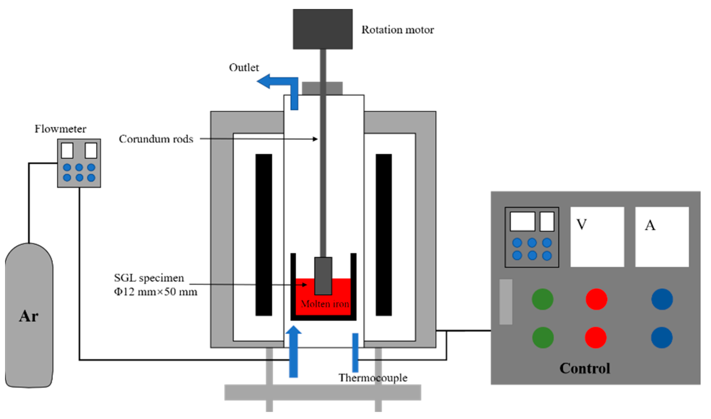
2.2. Experimental Apparatus and Procedure

The prepared iron powder was heated to the set temperature in a tubular furnace (BLMT Inc., Henan, China) under an argon atmosphere (>99.999%), which was preserved for 1 h to ensure that the iron powder was completely melted. The experimental device is described in Figure 1. Then, one end of the corundum rod was connected to a rotating motor, so that the carbon brick at the other end was immersed in molten iron (20 mm) for 2 h. The rotation of the carbon brick was used to simulate the flow of molten iron. The size changes of the carbon brick samples were compared before and after the experiment, and the microstructure of the interface after the experiment was observed using SEM and EDS.

2.3. Characterization

In order to quantitatively analyze the influence of different factors on S-carbon brick dissolution, the carbon brick’s erosion degree Δd was defined based on the diameter of the carbon brick samples before and after the reaction. The equation is as follows [21,22]:
Δ d = d 0 d f t
where d0 represents the diameter of the carbon brick before the reaction, mm; df represents the diameter of the carbon brick after the reaction, mm; and t represents the reaction time, h.
The carbon brick’s erosion rate v was calculated using the following equation:
v = π × l × d 0 2 d f 2 × ρ × w c 4 × t × s × 100
where l represents the depth of the carbon brick immersed in molten iron, cm; ρ represents the density of the carbon brick, g/cm3; wc represents the carbon content of the carbon brick; t represents the reaction time, h; and s represents the reaction area, cm2.

3. Results and Discussion

3.1. Experimental Results

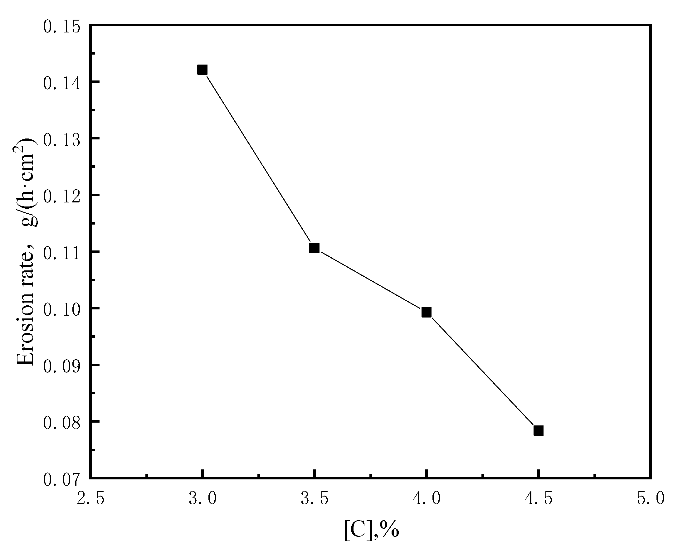
3.1.1. Influence of Carbon Content on the Corrosion of Bricks

The diameter of the carbon brick after the reaction was recorded every 5 mm, and an average value was taken for three measurements to obtain the average diameter of the carbon brick. According to Equations (1) and (2), the erosion degree and rate of the carbon bricks under different carbon contents can be calculated, and the results are shown in Table 3. The relationship between the carbon brick’s erosion rate and carbon content is shown in Figure 2. It can be found that the carbon brick’s erosion degree gradually decreases with the increase in carbon content, and the erosion rate decreases with the increase in carbon content.
Figure 3 shows a comparison of reaction interfaces between the four samples in the carbon content group. The sample in Figure 3a had minimum erosion after the reaction, and no obvious diameter reduction was observed macroscopically. With the decrease in carbon content, the diameter of the sample decreased distinctly. It can also be seen that the erosion was more intense under the carbon bricks.
The microstructures of carbon bricks after corrosion at 1500 °C at a carbon content of 3.0%, 3.5%, 4.0% and 4.5%, respectively, are presented in Figure 4. It can be seen from Figure 4 that the interface of the sample is stained with a large amount of platy molten iron, and a small number of cracks and holes covered with iron can be observed at the cross section. A large number of cracks after the reaction with a length of about 100 μm can be seen at the cross section. The cross section is stained with iron shots, and the iron–carbon boundary is very clear with the inconspicuous phenomenon of iron infiltration. In Figure 4d, fewer but larger cracks and the agglomeration and shedding of particles can be observed. An EDS detection showed that the particles are Al2O3, which could be found attached to iron shots, while the iron infiltration phenomenon around Si was more serious, indicating that the ceramic phase has a strong ability to resist erosion.

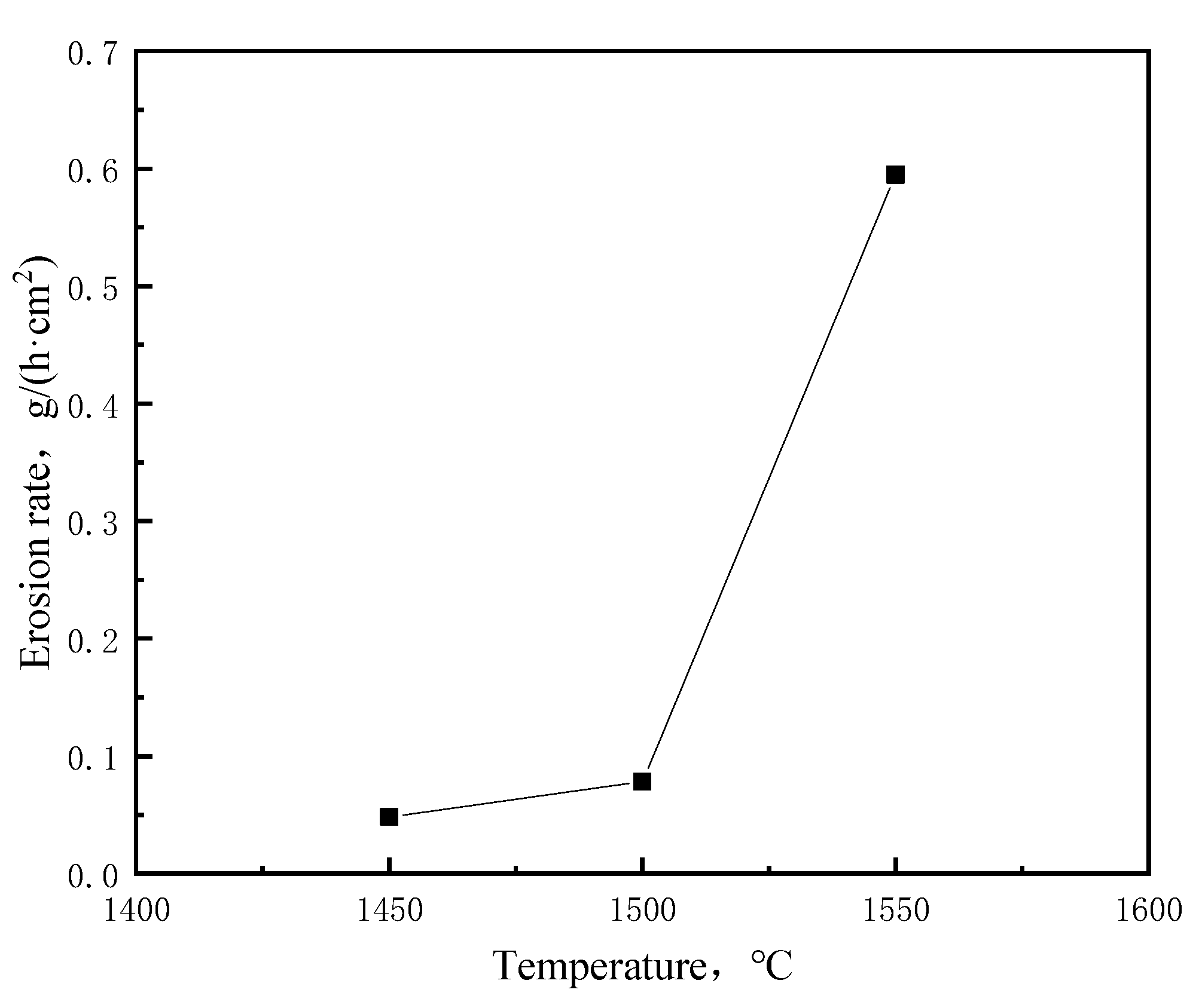
3.1.2. Influence of Temperature on the Corrosion of Bricks

The diameter after the reaction was measured every 5 mm, and an average value was taken for three measurements to obtain the average diameter of the carbon brick. Table 4 shows the erosion degree and rate of the carbon bricks under different temperatures according to Equations (1) and (2). It can be found that the carbon brick’s erosion degree increases with the increase in temperature, and the rate of erosion increases dramatically at temperatures above 1500 °C. The relationship between the carbon brick’s erosion rate and temperature is drawn in Figure 5. It can also be seen intuitively from Figure 5 that when the temperature rises from 1450 °C to 1500 °C, the increase in erosion rate of the carbon brick is much less than when the temperature rises from 1500 °C to 1550 °C. It shows that the influence of temperature on the dissolution of the carbon brick is not linear, and when the temperature is higher, the influence of rising temperature is greater.
Figure 6 shows a comparison of reaction interfaces between the three samples in the temperature group. The erosion of the standard carbon brick at 1500 °C is slight, and the reduction in diameter is not obvious, but the diameter reduction at the solid–liquid–gas interface is slightly larger, indicating that the erosion reaction at the three-phase interface is relatively severe. The sample in Figure 6 had a slightly rough surface and pores, which were stained with a small amount of iron shots. The erosion of the carbon brick at 1550 °C was very severe, and the lower part of the carbon brick had fallen off at the end of the reaction. The cracks and pores in Figure 6c are significantly larger than those in the other samples, indicating that the reaction of carbon bricks is more intense at higher temperatures.
The microstructures of the carbon bricks after corrosion at temperatures of 1450 °C, 1500 °C, 1550 °C and 1550 °C, respectively, are presented in Figure 7. It can be seen from Figure 7a that the interface of the sample was stained with a large amount of iron shots, and a large number of cracks after the reaction with a length of about 400 μm can be seen at the cross section. The size of the iron shots is relatively small, and iron infiltration could be observed at a depth of about 100~200 μm. In Figure 7b, cracks can clearly be seen at the cross section with a length of about 300~600 μm. It can be seen from Figure 7c that the interface of the sample at 1550 °C is attached by large iron shots with a size close to 0.5 mm, and long and wide cracks are running through the picture. As shown in Figure 7e, the surface scanning results show that the iron shots were attached to the surface, and the depth of the iron penetration was about 100 μm in Figure 7d.

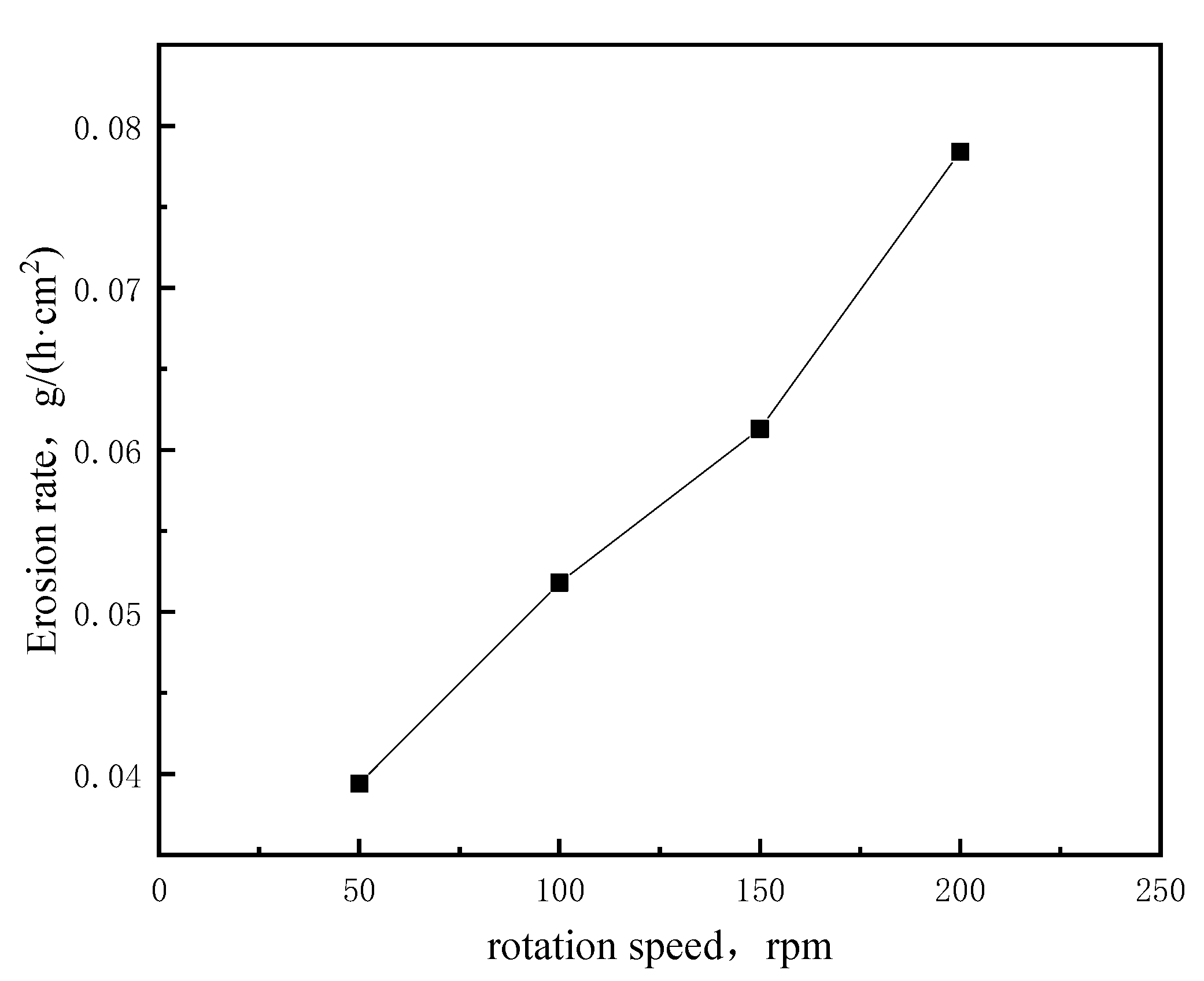
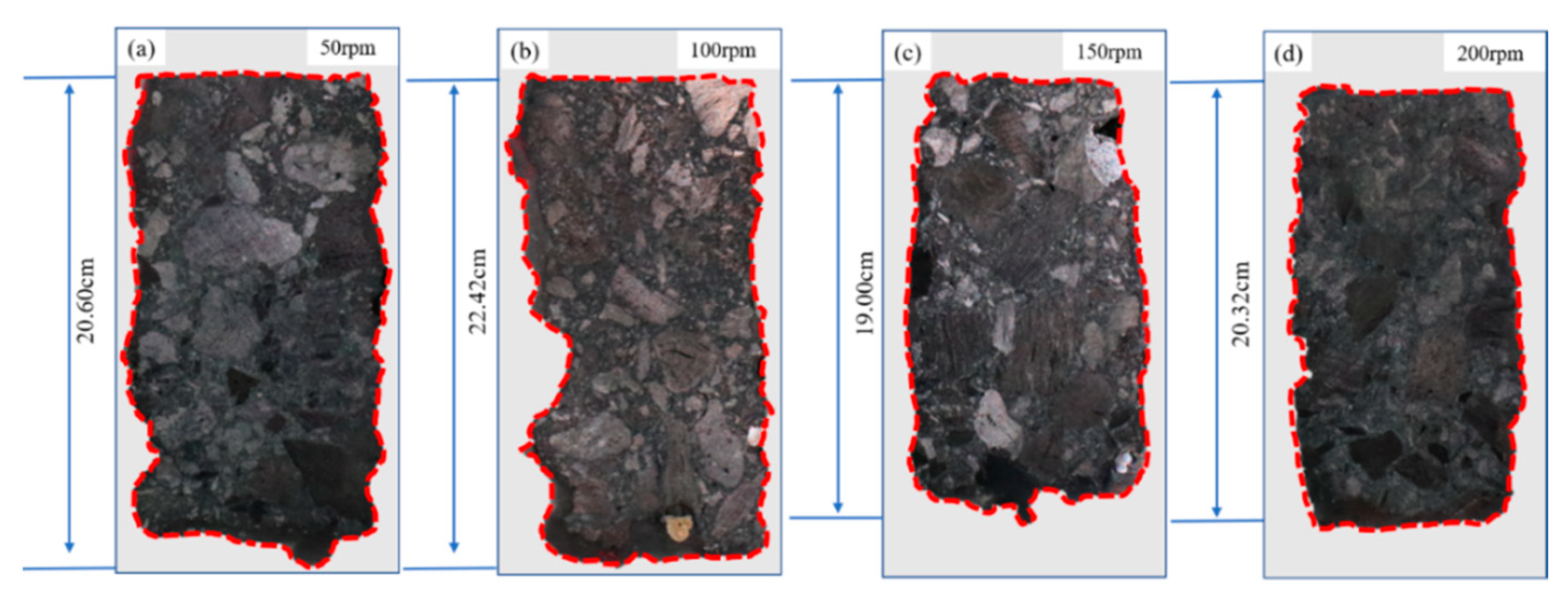
3.1.3. Influence of Rotational Speed on the Corrosion of Bricks

The diameter after the reaction was measured every 5 mm for three times to obtain the average diameter of the carbon bricks. Table 5 shows the erosion degree and rate of the carbon bricks’ erosion rate under different rotational speeds according to Equations (1) and (2). It can be found that the carbon bricks’ erosion degree gradually increases with the increase in rotational speed. The relationship between the carbon bricks’ erosion rate and rotational speed is drawn in Figure 8. Figure 8 shows intuitively that the erosion rate increases evenly in each interval of increasing rotational speed. The influence of rotational speed on the carbon bricks’ erosion rate is linear.
Figure 9 shows a comparison of reaction interfaces between the four samples in the rotational speed group. The sample in Figure 9a had the smallest erosion, which showed no obvious phenomenon from the macroscopic morphology, and distinct depressions can be observed in Figure 9b. The erosion rate of the carbon brick increases slightly with the increase in rotational speed.
The microstructures of carbon bricks after corrosion at rotational speeds of 200 rpm, 150 rpm, 100 rpm and 50 rpm, respectively, are presented in Figure 10. In Figure 10a, cracks with a length of about 300~600 μm could be clearly seen at the cross section. The interface of the sample in Figure 10b is rough and uneven, and the fragment of Al2O3 can be seen at the cross section with cracks and pores of about 400 μm. In Figure 10d, complete iron shots were attached to the brick, and the ferric infiltration was very obvious with a depth of less than 100 μm.

3.2. Mechanism Analysis

3.2.1. Dissolution of Carbon

In the actual production process, the penetration of hot metal and the dissolution of carbon bricks caused by the molten iron lead to serious erosion of the carbon bricks and threaten the safety and normal operation of the blast furnace in the later period of service. The carbon-undersaturated molten iron directly contacts the carbon bricks of the furnace hearth and forms an iron–carbon interface. The carbon dissolution on the interface is the key step in the carbon brick dissolution. The processes of carburization, infiltration and scour of molten iron during erosion by molten iron were simulated by using unsaturated molten iron and the rotating cylinder method. Under the experimental conditions, the saturated solubility of carbon in molten iron at 1500 °C is 5.00%, which can be calculated by Equation (3), which is as follows:
C S = 1 . 34 + 2 . 54 × 10 3 T 273 0 . 35 P 0 . 54 S + 0 . 04 Mn 0 . 30 Si
where T is the thermodynamic temperature (K); and [i] represents the mass percentage of each element in molten iron.
The carbon content of molten iron in the experiment was 4.5%, which was not saturated, so carburizing of molten iron occurred. It can be expressed as the following two chemical reactions:
C = [ C ] Δ G Θ = 22590 42.26 T   KJ / mol  
C + 3 Fe = Fe 3 C Δ G Θ = 10530 10.20 T   KJ / mol  
Equation (4) is the dissolution of solid carbon, and Equation (5) is the formatting of cementite. Figure 11 shows that the standard Gibbs free energy of Equation (4) is always lower than that of Equation (5) in the experimental temperature range, which proves that the carbon dissolution reaction is the dominant step of the carburizing reaction. Since carbon is the main component of carbon bricks, it is considered that the main way that molten iron erodes carbon bricks is to dissolve carbon into molten iron.
When the reaction is in equilibrium, the standard Gibbs free energy of Equation (4) is as follows:
Δ G Θ = R T ln K = 2.303 R T lg K
lg K = lg a C a solid = lg a C = lg w [ C ] + lg f C
lg w [ C ] = 1179.81 T + 2.21 lg f C
According to the Wagner model [23], the activity coefficient can be calculated using the following equation:
lg f C = e C C w [ C ] + e C Si w [ Si ] + e C Mn w [ Mn ] + e C P w [ P ] + e C S w [ S ] + e C Ti w [ Ti ]
Combining Equations (8) and (9), we can obtain the following:
lg w [ C ] = 1179.81 T + 2.21 e C C w [ C ] e C Si w [ Si ] e C Mn w [ Mn ] e C P w [ P ] e C S w [ S ] e C Ti w [ Ti ]
where eij is the interaction coefficient of element j on element i in molten iron, and the value is shown in Table 6.
According to Equation (10), the temperature, mass fraction of elements in molten iron and activity interaction coefficient between the elements affect the carbon dissolution reaction. When ecj > 0, the carbon activity coefficient increases with the increase in the mass percentage of element j in molten iron, resulting in a decrease in the solubility of carbon in molten iron. When ecj < 0, the activity coefficient of carbon decreases with the increase in the mass percentage of element j in molten iron, resulting in an increase in the solubility of carbon in molten iron.

3.2.2. Flow of Molten Iron

The shear stress on a hearth wall caused by molten iron flow is affected by flow velocity, but the shear action is very limited. The flow rate of molten iron between the dead stock and the sidewall of a hearth is generally 10−4~10−3 m/s, and the maximum shear stress calculated is 10−2 Pa. However, the flow of molten iron has a great influence on the convective heat transfer coefficient of molten iron, and the increase in the convective heat transfer system would affect the temperature of the hot surface of carbon bricks on the sidewall of a hearth, so that the carbon content of molten iron decreases and the carbon unsaturation increases, thus accelerating the dissolution of carbon bricks.
The convection heat transfer between a hearth and molten iron can be expressed by the following expressions:
N u = 0.68 Re 1 / 2 Pr 1 / 3
Re = ρ v d μ
Pr = C p μ k
N u = h d k
where v is the flow rate of molten iron, m/s; d is the distance between the molten iron and the hearth’s sidewall, m; μ is the dynamic viscosity of molten iron, Pa·s; Cp is the specific heat capacity of molten iron, J/(kg·K); k is the thermal conductivity of molten iron, W/(m·K); and h is the convective heat transfer coefficient, W/(m2·K).
The flow rate of molten iron can be obtained from the utilization coefficient of BF and the dead stock of a hearth as follows:
v = η V ρ π 4 d 1 2 d 2 2 π 4 d 2 2 ε t
where η is the blast furnace’s utilization coefficient, t/(m3·d); V is the blast furnace’s volume, m3; d1 and d2 are the hearth and dead stock’s diameters, respectively, m; ε is the porosity of the dead stock; and t is time, s.
In the above equation, ρ is related to the carbon content and temperature of molten iron, while the dynamic viscosity and thermal conductivity of molten iron are related to temperature, which can be expressed as follows:
ρ = 8750 69.6 C 1.15 T
μ = 0.3699 × 10 3 e 41.4 × 10 3 / R T + 273
λ = 45.14   exp - 0 . 0013 T
By summing up the above equations, the relationship between the convective heat transfer coefficient and the hot-surface temperature of the hearth’s sidewall can be obtained as follows:
h = 0.68 ρ v d μ 1 / 2 C p μ k 1 / 3 k d
T = T M q h
where TM is the temperature of molten iron, °C; and q is the heat flow intensity, W/m2.
According to Equations (19) and (20), the increase in flow rate increases the convective heat transfer coefficient, thus increasing the hot-surface temperature of the hearth’s sidewall, which leads to an increase in carbon unsaturation in molten iron and promotes the dissolution reaction of carbon bricks in molten iron. As a result, the erosion rate of the carbon bricks in the hearth’s sidewall is increased.

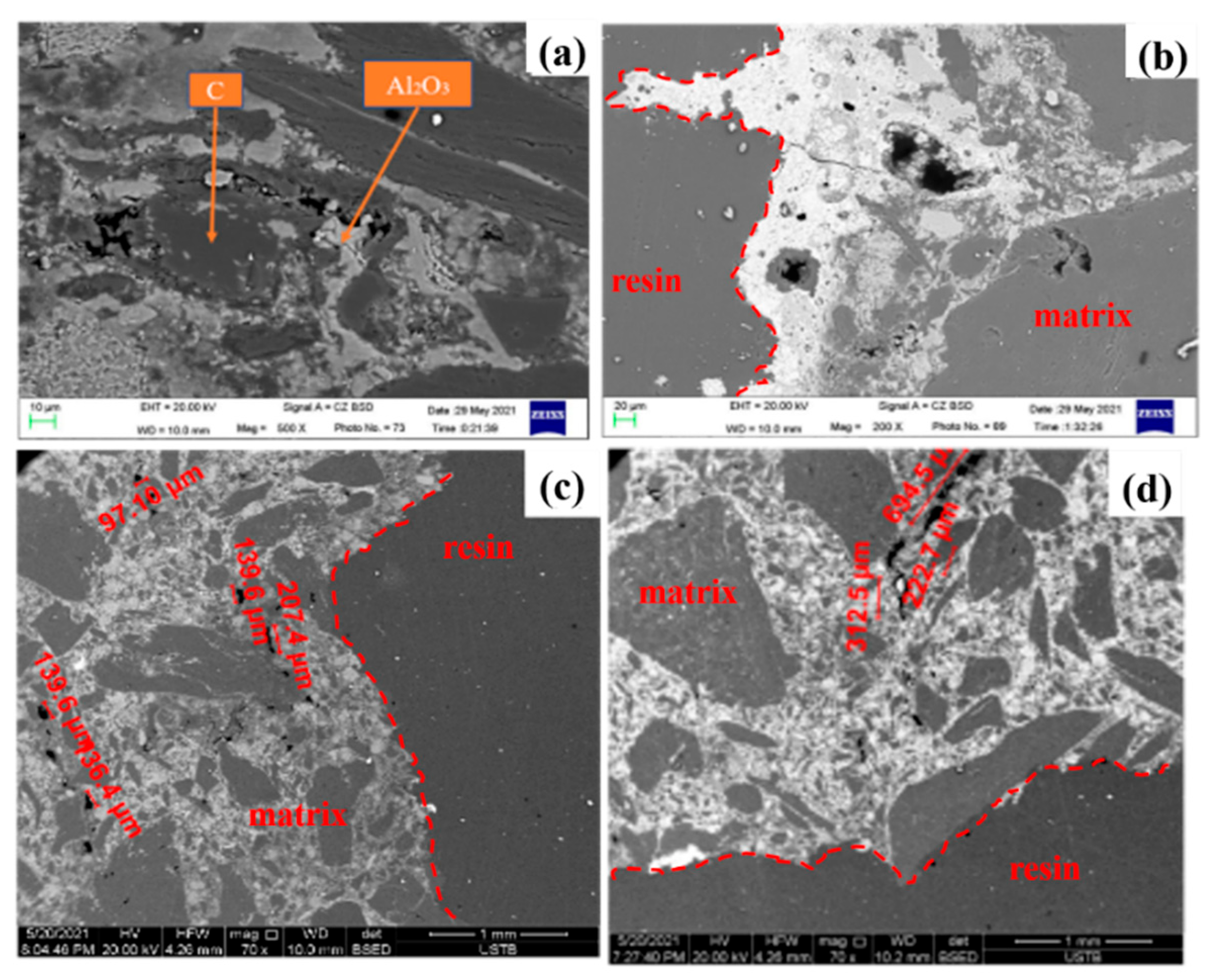
3.2.3. Erosion Mechanism

The erosion of S-carbon bricks in molten iron can be divided into the following processes as shown in Figure 12:
(1)
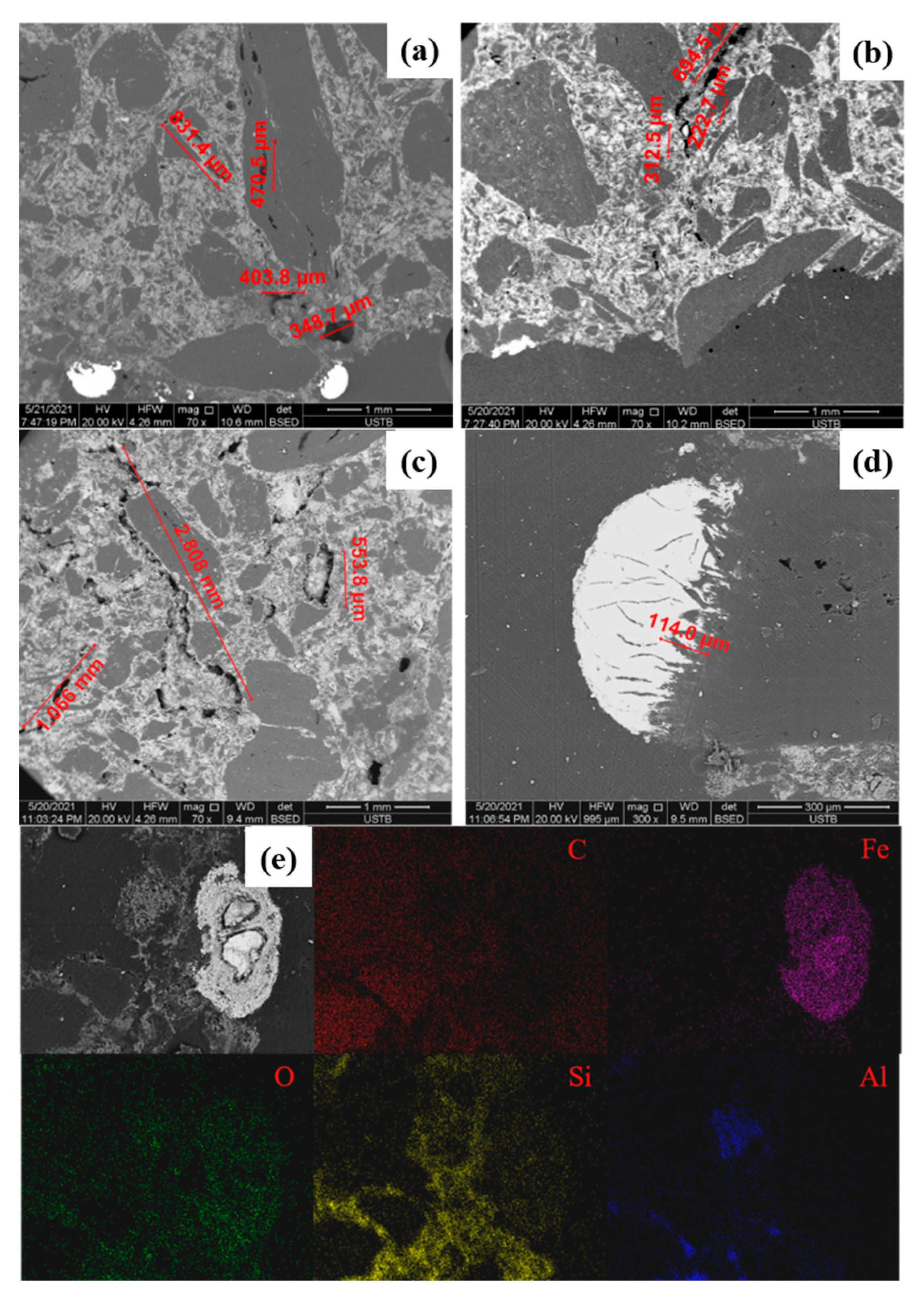
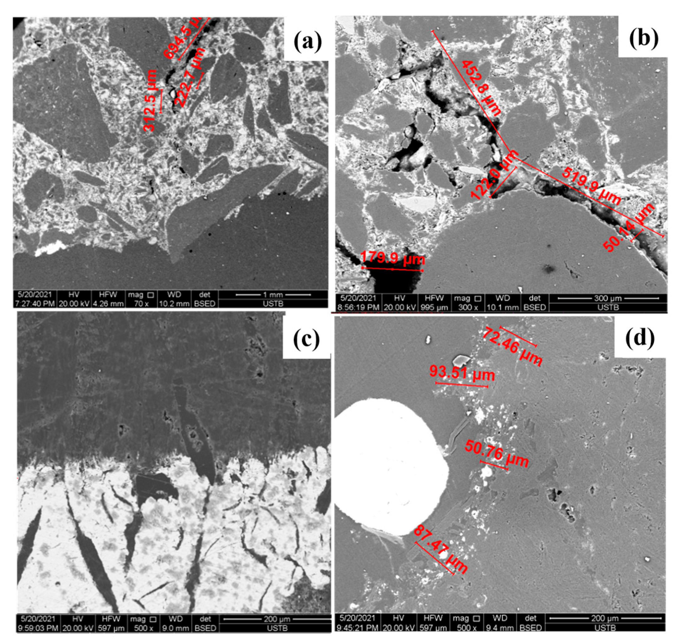
Molten iron is in direct contact with the carbon bricks and penetrates inwardly along the pores of the carbon bricks;
(2)
Molten iron will continue to permeate along the permeation channel, forming dendritic permeation;
(3)
Due to the infiltration of molten iron, the properties of the carbon bricks change, and the carbon bricks form an embrittlement layer and powdery particles;
(4)
The carbon brick dissolves into molten iron, making the iron and carbon boundaries migrate toward the carbon brick.

4. Conclusions

In this research, the reaction behavior at the iron–carbon interface was explored, which provides a theoretical basis for the influences of temperature, carbon content and circulation of molten iron. Through the rotating cylinder method, this study simulated an S-carbon brick in the hearth of a hot-metal dissolution reaction, researched the influence of three factors on the brick’s corrosion reaction and observed microstructures before and after the reaction. The main conclusions are as follows:
(1)
The dissolution reaction of carbon bricks is affected by the carbon content, temperature and flow rate of molten iron. The erosion degree and dissolution rate of a carbon brick decrease with an increase in carbon content. The erosion degree and rate of a carbon brick increase with an increase in temperature and flow rate, while temperature has a stronger effect on erosion at temperatures above 1500 °C.
(2)
The iron–carbon interfacial reaction was analyzed from the perspective of thermodynamics. The main reaction for carbon brick dissolution was obtained. During the erosion process, the Fe-C reaction almost does not work, and the flow of hot iron plays a major role.
(3)
The mechanism of three factors influencing the erosion of carbon bricks is found. Increasing the temperature and decreasing the carbon content would lead to a decrease in carbon dissolution in molten iron. The velocity of molten iron would not only affect the shear stress caused by scouring but also increase the unsaturation of carbon in molten iron, leading to the accelerated dissolution of carbon bricks.

Author Contributions

Conceptualization, C.W.; methodology, Y.L.; validation, H.S. and Z.W.; data curation, H.S. and Z.W.; writing—original draft preparation, H.S.; writing—review and editing, C.W.; visualization, H.S. and Z.W.; supervision, Y.L.; project administration, Y.Z. and J.Z.; funding acquisition, Y.Z. and J.Z. All authors have read and agreed to the published version of the manuscript.

Funding

This work was financially supported by the National Natural Science Foundation of China (No. 52204334) and the Project of SKLAM (Nos. 41622017 and K22-05).

Data Availability Statement

Data not available due to commercial restrictions. Due to the nature of this research, participants of this study did not agree for their data to be shared publicly, so supporting data is not available.

Conflicts of Interest

The authors declare no conflict of interest.

References

  1. Liu, Z.J.; Zhang, J.L.; Zuo, H.B.; Yang, T.J. Recent progress on long service life design of Chinese blast furnace hearth. ISIJ Int. 2012, 52, 1713. [Google Scholar] [CrossRef] [Green Version]
  2. Song, M.S.; Yu, Z.J.; Zou, Z.Q. Research and development of long campaign technologies of blast furnace at WISCO. Iron Steel 2000, 7, 5–9. [Google Scholar]
  3. Song, M.S.; Zou, Z.Q.; Yu, Z.J. Latest development of refractory used for blast furnace lining. China Metall. 2005, 11, 6–10. [Google Scholar]
  4. Zhang, S.R.; Song, M.S. Necessity of applying real micro-porous carbon block for long-life blast furnace. Iron Steel 2012, 47, 9–15. [Google Scholar]
  5. Zuo, H.B.; Wang, C.; Zhang, J.L. Application status and important technical indexes of BF hearth refractory. Iron Steel 2015, 50, 1–6. [Google Scholar]
  6. Inada, T.; Kasai, A.; Nakano, K. Dissection Investigation of Blast Furnace Hearth—Kokura No. 2 Blast Furnace (2nd Campaign). ISIJ Int. 2009, 49, 470–478. [Google Scholar] [CrossRef] [Green Version]
  7. Jiao, K.X.; Wang, C.; Zhang, J.L. Heat Transfer Evolution Process in Hearth Based on Blast Furnace Dissection. JOM 2020, 72, 1935–1942. [Google Scholar] [CrossRef]
  8. Li, Y.W. Preparation of Ceramic-Bonded Carbon Block for Blast Furnace. Metall. Mater. Trans. A 2014, 45, 477–481. [Google Scholar] [CrossRef]
  9. Yang, D.X.; Liu, Y.G.; Fang, M.H. Study on the slag corrosion resistance of unfired Al2O3–SiC/β-Sialon/Ti(C, N)–C refractories. Ceram. Int. 2014, 40, 1593–1598. [Google Scholar] [CrossRef]
  10. Yong, D.; Ran, L.; Jiao, K.X. Evolution and mechanism of dissolutive wetting between hot metal and carbon brick. J. Eur. Ceram. Soc. 2022, 42, 4420–4428. [Google Scholar]
  11. Fan, X.Y.; Jiao, K.; Zhang, J.; Cao, R.; He, R.; Wang, K. Study on physicochemical properties of Al2O3-SiC-C castable for blast furnace. Ceram. Int. 2019, 45, 13903. [Google Scholar] [CrossRef]
  12. Deng, Y.; Liu, Q.; Zhang, J.L. Erosion of Carbon Brick by Zinc in Hearth of Blast Furnace. ISIJ Int. 2019, 60, 226–232. [Google Scholar] [CrossRef] [Green Version]
  13. Deng, Y.; Jiao, K.X.; Liu, Z.J. Effects of Coke Ash on Erosion of Carbon Composite Brick. ISIJ Int. 2019, 59, 412–420. [Google Scholar] [CrossRef] [Green Version]
  14. Jiao, K.X.; Feng, G.X.; Zhang, J.L. Characterization and formation mechanism of graphite-rich iron protective layer in blast furnace hearth. Fuel 2021, 306, 121665. [Google Scholar] [CrossRef]
  15. Deng, Y.; Liu, R.; Jiao, K.X.; Chen, Y.B. Wetting behaviour and mechanism between hot metal and carbon brick. J. Eur. Ceram. Soc. 2021, 41, 5740. [Google Scholar] [CrossRef]
  16. Zuo, H.B.; Wang, C.; Zhang, J.L.; Shao, J.G.; Zhao, Y.A.; Jiao, K.X. Comparison of oxidation behaviours of novel carbon composite brick with traditional carbon brick. Ceram. Int. 2015, 41, 7929. [Google Scholar] [CrossRef]
  17. Xu, R.Z.; Zhang, J.L.; Zhang, G.H.; Ma, R.Y.; Zhao, Y.A. Corrosion behaviour of carbon composite brick in high alumina slags. Ceram. Int. 2018, 44, 5242. [Google Scholar] [CrossRef]
  18. Jiao, K.X.; Fan, X.Y.; Zhang, J.L.; Wang, K.D.; Zhao, Y.A. Corrosion behaviour of alumina-carbon composite brick in typical blast furnace slag and iron. Ceram. Int. 2018, 44, 19981. [Google Scholar] [CrossRef]
  19. Deng, Y.; Zhang, J.L.; Jiao, K.X. Dissolution mechanism of carbon brick into molten iron. ISIJ Int. 2018, 58, 815. [Google Scholar] [CrossRef] [Green Version]
  20. Wang, G.E.; Wang, Y.; Xie, B. Effects of oxides contents in vanadium slag on corrosion mechanism of MgO-C bricks. J. Iron Steel Res. 2012, 19, 36–42. [Google Scholar] [CrossRef]
  21. Wang, C.; Zhang, J.L.; Chen, W. Comparative Analysis on the Corrosion Resistance to Molten Iron of Four Kinds of Carbon Bricks Used in Blast Furnace Hearth. Metals 2022, 12, 871. [Google Scholar] [CrossRef]
  22. Deng, Y.; Zhang, J.L.; Jiao, K.X. Effects of temperature and composition of molten iron on dissolution behaviour of carbon brick. Iron Steel 2018, 53, 25–31. [Google Scholar]
  23. Guo, H.J. Physical Chemistry of Metallurgical Tutorial, 2nd ed.; Metallurgical Industry Press: Beijing, China, 2006. [Google Scholar]
Figure 1. Molten iron corrosion experimental apparatus.
Metals 13 01240 g001
Figure 2. Relationship between the erosion rate of carbon bricks and the carbon content of molten iron.
Metals 13 01240 g002
Figure 3. Interface of carbon bricks after reaction in the carbon content group. (a):4.5% C; (b):4.0% C; (c):3.5% C; (d):3.0% C.
Metals 13 01240 g003
Figure 4. SEM micrographs of bricks in the carbon content group. (ad) are different carbon content.
Metals 13 01240 g004
Figure 5. Relationship between the erosion rate of carbon bricks and the temperature of molten iron.
Metals 13 01240 g005
Figure 6. Interface of carbon bricks after reaction in the temperature group. (ac) are different temperature; (a): 20.20 cm; (b): 20.32 cm; (c): 12.60 cm.
Metals 13 01240 g006
Figure 7. SEM micrographs and SEM of the bricks in the carbon content group. (ad) are 1450, 1500, 1550, and 1550 °C respectively and (e) is a surface scan image of 1500 °C.
Metals 13 01240 g007
Figure 8. Relationship between the erosion rate of carbon bricks and the rotational speed of molten iron.
Metals 13 01240 g008
Figure 9. Interface of carbon bricks after reaction in the rotational speed group. (ad) are interface after different rotational speed experiments.
Metals 13 01240 g009
Figure 10. SEM micrographs of the bricks in the rotational speed group. (ad) are micrographs of different rotational speed.
Metals 13 01240 g010
Figure 11. Relationships between the standard Gibbs free energy of the carburizing reaction and temperature.
Metals 13 01240 g011
Figure 12. Erosion process of hearth carbon brick.
Metals 13 01240 g012
Table 1. Main chemical constituents of S-carbon bricks.
ContentCAl2O3SiO2SiCTiO2Others
Value/%76.158.747.416.910.220.57
Table 2. Experimental conditions of S-carbon brick dissolution.
FactorsNo.Temperature
/°C
Speed
/rpm
Composition of the Molten Iron/%
(C)(Si)(Mn)(P)(S)(Ti)
Carbon contentC-115002003.00.40.30.10.040.10
C-215002003.50.40.30.10.040.10
C-315002004.00.40.30.10.040.10
C-415002004.50.40.30.10.040.10
TemperatureT-114502004.50.40.30.10.040.10
T-215002004.50.40.30.10.040.10
T-315502004.50.40.30.10.040.10
Rotational
speed
V-11500504.50.40.30.10.040.10
V-215001004.50.40.30.10.040.10
V-315001504.50.40.30.10.040.10
V-415002004.50.40.30.10.040.10
Table 3. Influence of carbon content on the erosion of carbon bricks.
NumberPre-Reaction
Diameter, mm
Post-Reaction Diameter, mmErosion Degree, mm/hErosion Rate, g/(h·cm2)
C-111.819.682.130.1421
C-211.8910.231.660.1106
C-311.8810.391.490.0993
C-411.9110.741.180.0784
Table 4. Influence of temperature on the erosion of carbon bricks.
NumberPre-Reaction Diameter, mmPost-Reaction Diameter, mmErosion Degree, mm/hErosion Rate,
g/(h·cm2)
T-111.8911.170.730.0484
T-211.9110.741.180.0784
T-311.973.058.930.5949
Table 5. Influence of rotational speed on the erosion of carbon bricks.
NumberPre-Reaction Diameter, mmPost-Reaction Diameter, mmErosion Degree, mm/hErosion Rate,
g/(h·cm2)
V-111.8911.300.590.0394
V-211.9011.120.780.0518
V-311.8710.950.920.0613
V-411.9110.741.180.0784
Table 6. Value of the interaction coefficient of elements in molten iron at 1600 °C.
Interaction
Coefficient
e C C e C Si e C Mn e C P e C S e C Ti
Value0.140.08−0.0120.0510.016−0.041
Disclaimer/Publisher’s Note: The statements, opinions and data contained in all publications are solely those of the individual author(s) and contributor(s) and not of MDPI and/or the editor(s). MDPI and/or the editor(s) disclaim responsibility for any injury to people or property resulting from any ideas, methods, instructions or products referred to in the content.

