1. Introduction
All industries face climate challenges and strive to adopt efficient technologies and equipment for reduced resource and energy consumption. For these reasons, heat-intensive branches such as power generation, petrochemistry, metallurgy, and heavy machinery increase the size of their facilities to enhance productivity and energy efficiency. Both nuclear and petrochemical industries claim the rigorous requirements for the quality of large steel parts manufacturing [
1,
2,
3,
4,
5,
6,
7].
The hearts of the atomic power stations and refineries are thick-wall steel vessels: reactor pressure vessels (RPV) and petrochemical columns. For example, the weight of the billet of the cylindrical part of the body of the water–water energetic reactor VVER-1300 (Kramatorsk, Ukraine) (height and outer diameter of about 5 m, wall thickness of up to 20 cm) is 117.4 t [
7]. The petrochemical columns reach more than 905 t in weight, and some of them have wall thicknesses up to 305 mm [
6]. For such massive structures, ingots of several hundred tons are manufactured. Ingot’s weight for the mentioned-above part of the VVER-1300 makes 450 tons [
7].
However, the bigger an ingot, the more severe segregation of elements occurs, reducing product quality and yield. This is the reason the conventional production process of ingot casting is quality limited. It is well-know that the biggest problem in heavy ingot quality is eliminating typical solidification problems: shrinkage cavities and porosity under dendrite bridges in the top and central part of the ingot and segregation of elements on cross-section and height. To avoid both shrinkage porosity and element segregation, the solidifying metal volume should be minimized and held under hot topping by a melt as long as possible. To mitigate segregation effectively, various measures are developed and implemented, including refining to minimize impurities and microalloying to counteract their harmful effects, as well as the employment of a variety of special melting techniques (most often electroslag remelting).
In the electroslag remelting processes, an ingot is formed in a water-cooled copper mold at a slow rate of consumable electrode melting, which constantly provides liquid metal coming in a liquid metal pool by fine droplets through the refining liquid slag. At the ESR ingot formation, the composition of the solidifying metal is permanently renewed, mitigating segregation, and heated, keeping effective hot topping of shrinkages. ESR is the most widely used process for high-quality heavy forging ingot manufacturing.
However, the maximum mass of a solid ESR ingot today is 150–200 tons, which is due to the appearance of the same segregation problems as in a conventional ingot cast in an iron mold: with an increase in the cross-section, the efficiency of heat removal by the mold reduces, and the volume and depth of the metal pool increase, causing a deepening of a mushy zone accompanying all known phenomena listed above.
A good solution, in this case, is to divide the solidifying volume, as it can be made by switching to the hollow ingot, where the cross-section of a solidifying metal compared to solid ingots of the same mass is at least twice less, and the production of hollow ingots through both casting and electroslag remelting techniques is widely acknowledged as a highly efficient method for low-segregation big part manufacturing. However, due to the fact that hollow ingots production, both in a cast iron mold and with ESR, requires precise observance of the specified parameters of the technological process, it is commercialized only at a few plants with a high production standard. The published results are presented in the following parts of the article and discuss both proven and further possibilities provided by hollow ingots, which clearly show the actual challenge to scale up the size of hollow ingots produced by ESR and expanding their application for the manufacture of thick-walled shells of a large diameter in view of their further implementation for pressure vessels for the nuclear and petrochemical industries.
2. Requirements for Pressure Vessel Steel Quality and Content of Impurities
The steel grades for nuclear reactor pressure vessels are similar worldwide and belong to the family of CrMoV heat-resistant steels. The petrochemical industry’s heat exchangers and process reactors are also commonly manufactured from low-alloy chromium-molybdenum steels (1 to 3% Cr and 0.5 to 1% Mo) [
8,
9].
Steel producers emphasize that the construction of reactors and vessels makes strict requirements for steel quality and content of residual and alloying elements (Mn, Ni, Cu, P), playing an essential role in irradiation hardening and embrittlement [
9]. For example, for the VVER-1000 reactor pressure vessels (Plzeň, Czech Republic), the 15Kh2NMFA steel (15Cr2NiMoV) was improved by alloying by nickel and deep refining from impurities. As shown by experimental data, the radiation resistance of Cr-Mo-V steels substantially depends on the content of harmful impurities, primarily such as phosphorus and copper [
9,
10].
The case with the Belgian pressurized water reactor (PWR) Doel 3 (where thousands of defects have been found in the RPV body) shows that metal homogeneity plays a crucial role. Metallurgical investigations support conclusions that the flaws appeared at manufacturing because of hydrogen content. Solidification of any alloys is accompanied by segregation zones where hydrogen diffuses at further cooling, and its accumulation implies the flaws formation [
11]. It is well-known that the liquate-enriched segregation areas are the most subjected to hydrogen embrittlement.
To reduce the content of hydrogen and other gas content in steel products, vacuum refining methods are widely used. This treatment is a very efficient tool but is unable to eliminate both the gases and nonmetal inclusion formation entirely because the segregation of elements is an unavoidable problem due to the nature of alloys’ solidification as shown by M. Flemings and many others [
12,
13,
14,
15,
16], which increases with ingot diameter growth.
The macrosegregation (A and V types, freckles, etc.) manifestations depend on the chemical composition of an alloy, dissimilarity in elements’ solubility, density of forming phase, and convection flows at non-equilibrium solidification. The two most efficient ways to alleviate macrosegregation at heavy ingots solidification are: decreasing the content of liquation-prone elements by refining and/or preventing their accumulation at the crystallization front by solute-enriched liquid phase dilution by “fresh” melt additions. Both actions are inherent to special melting processes (electroslag remelting, vacuum arc remelting, electron beam cold hearth melting).
Today’s requirements for nuclear reactor parts include a guaranteed service life of the RPV of 60–80 years, creating a new challenge for steel grades composition, quality, and structure uniformity of forged parts. Ensuring steel cleanness is essential, but it alone cannot guarantee extended durability and the required by nuclear code particular set of properties. Therefore, enhancing the composition of RPV steels and the solidification conditions of ingots is imperative.
The research of new modifications of 15Cr2MoV steel for RPV showed higher properties than typical VVER materials under irradiation and treatment [
15]. Results were achieved due to chemical composition adjustment to increase the lower limits of carbon and chromium (up to 0.15 and 2.7 %wt, respectively). The nickel as an alloying additive (before Ni was adopted as an admissible impurity) increased hardenability in large cross-section billets (0.2 … 0.4 %wt). Furthermore, the upper level of the permissible content of harmful impurities in modified 15Cr2NiMoV clean steel (modification A) was drastically reduced, namely (%wt), sulfur to 0.007, copper to 0.07, and phosphorus to 0.007. Niobium microalloying was also applied to reliably ensure the high strength category (KP-45) and to increase the steel tempering resistance [
16].
The steel SA 508 from the same family of low-alloy steels is used for the Westinghouse AP-1000 reactor pressure vessel [
17]. Producer specifications for SA-508 Grade 3 Class 1 for ‘core region forgings’ has additional restrictions on the following chemical elements (%wt): Phosphorous ≤ 0.01, vanadium ≤ 0.05, sulfur ≤ 0.01, nickel ≤0.85, chromium ≤ 0.15, and for non-core regions the above limits on sulfur and chromium are required by Westinghouse specifications [
18].
Similar requirements were formulated for producing the ultra-large diameter 20 MnMoNi55 (similar to SA508, Cl.3 steel) forgings for reactor pressure vessels, including particular efforts for minimizing the tramp elements such as phosphorus, sulfur, arsenic, tin, antimony, and copper to provide the following metallurgical properties: sufficiently uniform carbon distributions in the forgings; a lowest possible content of hydrogen, non-metallic inclusions, and oxygen [
19].
The macrosegregation problem increases with increasing both the ingot diameter (mass) and content of alloying elements in steel grade. The Japan Steel Work (JSW) noted that the maximum possible ingot weight strongly affects the size and weight of nuclear vessel components. The resulting product typically makes less than ~30% of the ingot weight (~10% in the case of complex shapes) [
20]. For example, for producing less alloyed A508 grade, the JSW uses ingots up to 600 t in weight, but for 2.25Cr-1Mo steel grade, the largest size ingot the JSW uses is 250 tons. Thus, it is possible to produce larger-sized ingots for 2.25Cr-1Mo in principle, but quality requirements will not be satisfied. For Grade 91 steel, the ingot weight is also currently limited to 120 t because of segregation problems [
21].
Y. Tanaka [
21] assumed that high-quality RPV material should have homogeneity, no harmful internal defects, good inspectability, low aging embrittlement susceptibility—including neutron irradiation embrittlement—good fracture toughness, weldability, etc. Advanced refining, casting, forging, heat treatment, and machining technologies should be optimized and standardized to produce these qualities.
The focus of made modifications in composition was on refining and microalloying to enhance steel strength, corrosion resistance, and high-temperature toughness and fatigue to ensure vessels’ safety and resilience. The importance of high metallurgical quality metal parts for the reactor pressure vessel is indisputable. It is proved that just the metal parts with a homogeneous chemical composition without significant segregation can only provide the required set of mechanical and service properties under conditions of high temperatures and radiation exposure and keep resistance to embrittlement (including hydrogen) under cyclic loads for the service life of a nuclear reactor (the current target is not less than 80 years).
3. Hollow Ingots: State-of-the-Art and Challenges
The production of hollow ingots is not something completely new and unknown. The advantages in quality and efficiency of heavy hollow ingot manufacturing were proved, for example, by Kawasaki Steel Corporation in Japan [
22,
23,
24] and Framatome Creusot Forge site in France [
25]. Both companies have been using this type of cast ingots (weighing up to 200 tons) in iron molds for the manufacture of nuclear reactor pressure vessels and clearly stated the following advantages:
- -
favorable solidification conditions allow suppressing segregation (metal free of segregation at the inner surface and subsurface area, and with minimized development of A-type segregation), micro-porosity, anisotropy in the mechanical properties, and reduction of the irradiation embrittlement effect;
- -
clean internal surface and good inner quality ensure a more significant yield of forgings providing economic efficiency and a high safety factor relative to the risk of reactor failure [
25].
The production of heavy hollow ingots cast into an iron mold with a central air-cooled insert has been increasing recently. Several heavy machinery plants have already mastered this technology. The largest reported hollow mold-cast ingot weighs 240 t [
23,
26,
27,
28,
29,
30,
31]. Cylindrical forgings of 2.25Cr-1Mo and 2.25Cr-1Mo-0.25V grades have been produced for shells of diameters ranging from 1800 to 4200 mm, thickness from 150 to 180 mm, and lengths from 2500 to 4700 mm. The weights of these shells vary from 20 Mt to 60 Mt depending on the shell dimensions. Despite sufficiently different forging ratios, the microstructures and mechanical properties of shells produced from solid and hollow ingots cast in iron molds have no difference for all examined grades.
Thick-walled shells are usually made in two ways. Shells with a wall thickness of around 50–100 mm are made by bending thick rolled products with subsequent welding of the joint with one or two (for half rings) longitudinal seams, which are stress concentrators. In the designs of modern nuclear reactors, such shells are not used. Shells with a wall thickness of more than 150 mm are usually made by forging from steel conical (with a taper of 2–3) ingots with longitudinal edges (usually 12–18 edges to improve heat dissipation). Forged hollow billets from solid ingots weighing 200 t and more should not have porosity, cracks, slag inclusions, shrinkage cavities, or other defects. It is practically impossible to avoid defects in the head, bottom, and central parts of a solid heavy ingot. These parts are removed, and, therefore, the weight of the original ingot is usually set to three times the weight of the shell.
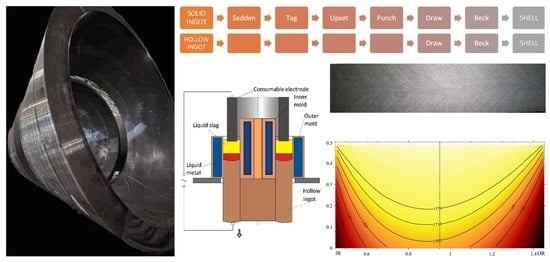
At the beginning of the forging process, a solid ingot is saddened to break up and refine the coarse as-cast structure at the surface, then the top part is drawn down to make a tag for handling convenience (
Figure 1).
After that ingot is upset to make the ingot diameter bigger with the further punch to remove the central part forming a hollow billet. Further operations for prepared forged hollow billet are the same as for hollow ingots—elongation and forging to specified dimensions (draw and beck).
Compared with a solid ingot at shells/pipes manufacturing, the advantages of a hollow ingot are very noticeable: shorter forging process: sadden, tag, upset, and punch stages are excluded, and the quantity of pre-forging heating operations is much less, which reduces connected energy consumption and oxidation losses [
28].
Reducing the number and duration (due to the less massive ingot wall) of interoperations, heating can help minimize losses from scale formation and further machining. Minimizing near-surface oxidation of grain boundary is even more crucial, which can cause crack initiation. In addition to these benefits, hollow ingots also offer energy, resources, and time savings, making shell manufacturing cost-effective.
Big-section ingots for heavy forgings of tens and hundreds of tons are still in high demand for nuclear reactor vessels, heat generator shells, power turbine cases, petrochemical columns, metallurgical equipment, and various thick-wall pipes. The heavy forgings with a hole inside reach nearly half the portfolio of orders of a heavy machinery plant manufacturing various thick wall shells for vessels, cases, rings, and pipes (
Table 1).
Safeguarding commercial secrets at the beginning of commercialization and the existence of only minor technical and organizational know-how in hollow ingots manufacturing constrained the widespread use of this technology worldwide. As a result, most hollow products are still made mainly from solid ingots.
This technology is undeservedly not often used enough, even though hollow ingot manufacturing provides a sufficiently higher yield for ESR hollow ingots and pipes than the procedure foreseeing solid ingot piercing. Metal yield at ESR hollows depends on ingot length (the longer, the better) and reaches 94–97%. This is 35–50% higher than at the conventional forging route for cylindrical shell fabrication from solid ingots. Such a big difference occurs because of much smaller top and bottom discard, no metal losses for tails at piercing, and sufficiently lesser scale formation due to the cut in the duration and number of preheating stages. The higher yield and less energy consumption of hollow ingot manufacturing improve efficiency and reduce the ecological footprint of heavy machinery.
Therefore, one of this article’s purposes is to change this situation in favor of ESR hollow ingot manufacturing. The clear benefits of hollow ingot manufacturing make us confident that modern electroslag remelting is the next step for further development of RPV manufacturing to improve both metal quality and yield.
6. Simulation of the Hollow ESR Ingot Solidification
The process of solidification modeling involves tackling a complex multiphysical problem that includes fluid flow, heat transfer, and solute diffusion. In the case of ESR ingot formation, electro and magneto dynamics also come into play. In order to prevent errors caused by overly complex mathematical descriptions of the ESR ingot formation process, a simplified model was developed, effectively capturing the studied phenomena’s physical essence and key aspects. The model comprises several tasks that correspond to characteristic physical phenomena associated with each other. These tasks involve determining the Joule heat release in a liquid slag bath, calculating the temperature field in the slag and metal baths while considering the batch flow of liquid metal from the electrode, and estimating a two-phase zone width. The last was taken as the measure of the degree of unfavorable manifestation of segregation processes in the ingot.
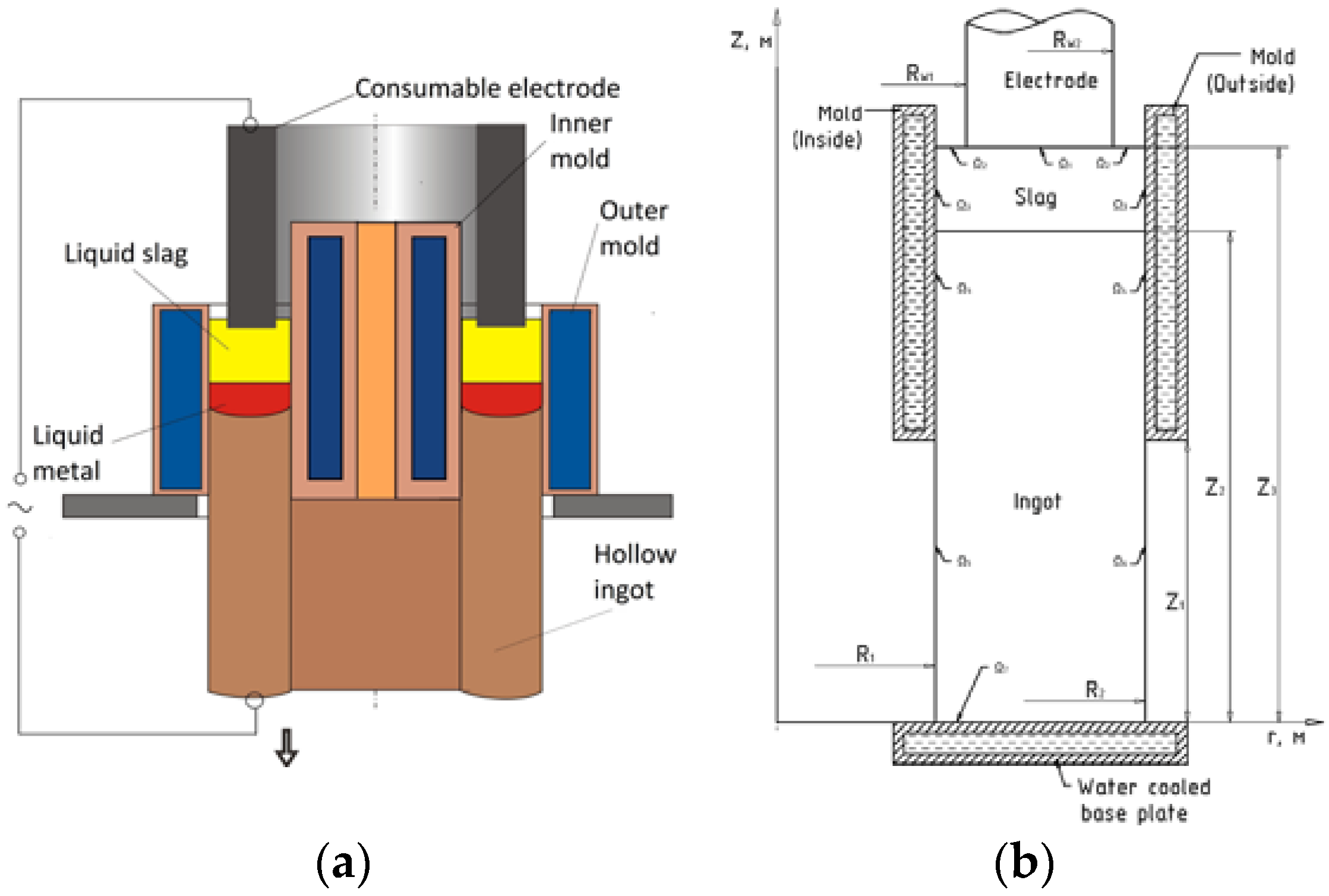
The direct electrical connection diagram (electric current flows in circuit “transformer—consumable electrode—molten slag—liquid metal bath—solidified ingot—bottom plate—transformer”) and tubular shape consumable electrode equidistantly located from both the inner and outer molds in the slag bath were assumed.
Figure 3b shows a schematic diagram for formulating the heat transfer problem in the calculated area.
The differential equation for the thermal conductivity of the slag and the ingot in a cylindrical coordinate system has the form:
where
heat capacity, density, and thermal conductivity, respectively;
—slag;
—ingot;
—a volumetric source of heating, which was described by the following equation:
where
—the power of Joule heat generated in the slag;
—thickness of the slag layer,
—the electrode cross-section,
Z2-growing height of the slag layer surface,
Z3-growing height of the solidifying ESR ingot.
Boundary conditions were formulated on all interfaces as follows:
where
—Stefan–Boltzmann constant;
—emissivity of the ingot and the slag surfaces, respectively;
1,2,3,in—heat transfer coefficients of the slag, ingot, base plate, and inner mold wall, respectively; λ
1,2—thermal conductivity of the slag and ingot respectively,
—the heat flow to the surface of the electrode;
—thermal radiation flux on the inner surface of the ingot;
—ambient temperature;
—the temperature of the water-cooled base plate;
—temperature of the mold.
Heat transfer in the interior part of the ingot at the interface occurs by radiation. The heat flux between and ingot surfaces was determined by control volume (zone) method. This method foresees keeping the heat balance for each calculated element. For the numerical solutions, the entire calculated volume, including solidified ingot and slag bath, was divided into equal parts in both radial and axial directions. To accurately model the increase of the ingot’s height, the number of elements in the computational network was dynamically adjusted in the axial direction. The new elements with a liquid metal temperature from a consumable electrode were added at specific intervals of time to fill the calculated elements between the slag surface and the metal. Simultaneously, other calculated elements shifted one step in the axial direction. To ensure optimal results, we selected a time step interval divisible by time for a new layer filling, which typically takes around one second and depends on the ESR process productivity.
Numerical solutions were received for the 15Cr1Mo1V steel and the slag 50CaF
2-25CaO-15SiO
2-5Al
2O
3-5MgO (%wt) that is suitable for the ESR in short collar mold with ingot withdrawing, the thermophysical properties of which are given in
Table 5.
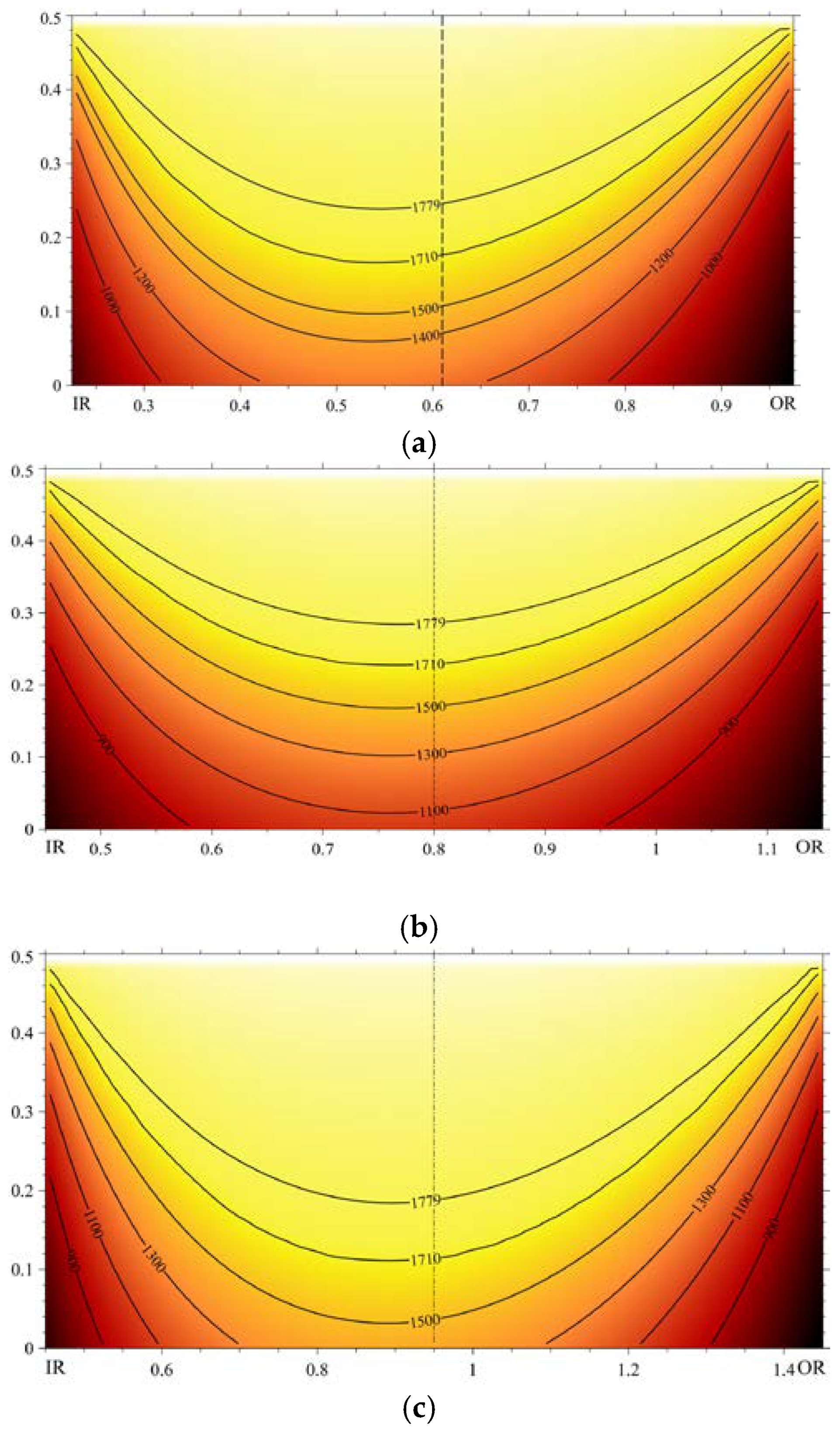
The mathematical simulation was performed for three variants of ESR hollow ingots solidification (where 2 pertains to both VPR #2 and #3 from
Table 4). The results of numerical experiments are presented as temperature distribution fields in solidifying hollow ESR ingots in
Figure 4, which were built for the upper part (0.5 m in height) of the ingot of 2 m in height.
A further increase in the calculations of the ingot height does not sufficiently change the temperature field and pool profile. Understandably, the bigger the thickness of a hollow ingot wall is, the deeper is the liquid metal pool and the more significant is the distance between liquidus and solidus lines, which contours the mushy zone (
Table 6) where the primary solidification-induced segregation forms.
In a previous study [
44], it was demonstrated that for an ESR ingot of a comparable steel grade and diameter of 3000 mm, the depth of the liquid metal pool is approximately 1600 mm, with a volume of nearly 4.65 m
3. Conversely, for hollow ingots with an outer diameter of 2900 mm and a wall thickness of 900 mm, the depth of the liquid metal pool is around 500 mm, and the volume is approximately 1 m
3. Therefore, in ESR hollow ingots, fluid flow is not as significant as in large ESR solid ingots of a similar outer diameter, and it does not have a significant impact on segregation.
7. Discussion
The results of numerical experiments show the important trends presenting the weighty arguments favoring manufacturing heavy ESR hollow ingots of large diameters.
The calculated depth of the liquid metal pool is less than half of the ingot wall thickness, which corresponds with our data for slab ingot manufacturing. The low-depth liquid metal pool allows for a production of heavy wall hollow ingots in short collar molds of small length that facilitate smooth withdrawing.
The extent of the mushy (two-phase) zone is also tiny (less than 80 mm in all simulated variants); in this case, the development of all types of segregation will be insignificant, which is an optimistic prognosis for the as-cast application of such hollow ingots without deformation.
Our predecessors have developed and proved an empirical rule for choosing the electric power for thin-wall hollow ESR ingots manufacturing. The rule was: the electric power put into the slag bath for remelting hollow ingots with certain inner and outer diameters should not be less than the sum of capacities needed for the manufacturing of both such solid ESR ingots of these diameters. However, our calculations performed for thick-walled ingots of large diameter showed that the operating temperature of the electroslag process (usually 1800–1900 °C) is provided by a much lower electric power, the value of which is equivalent to the power of the ESR for a solid ingot having a diameter equal to the outer diameter of a large thick-walled hollow ingot (in the range of simulated dimensions). Thus, ESR process thermal and electrical parameters strongly depend on hollow ingot geometry. For the simulated geometric dimensions at typical ingot formation rates, there is no need to increase the electric power beyond the value usually required for the ESR of solid ingots with the same outer diameter. Moreover, it provides the possibility of having higher-than-expected permissible productivity (compared with a solid ingot with the same diameter) of such hollow ingot formation. This preliminary conclusion is based on the predicted average temperature of the slag pool, and for a hollow ingot with an outer diameter of 2900 mm, the needed capacity of a power source is near 2600 kVA. Following another well-known rule, the lower the input power, the adequately lower the losses. Thus, it can also be preliminary stated that the power consumption at the ESR of large-diameter thick-walled hollow ingots will be close to or even less than necessary for manufacturing the solid ones of the same diameter.
The highly probable explanation is that the melting of a single electrode with a large diameter causes high overheat of the slag and metal in the solid ingot. The cooling surface of larger molds becomes insufficient for effective heat dissipation from a massive amount of a metal solidifying into a solid weighty ingot. Therefore, to receive an acceptable quality of big ingots, it is necessary to operate the process very slowly, but the electrical losses, in this case, increase drastically. On the contrary, the cooling surfaces of two molds at hollow ingots formation give much more favorable solidification conditions. We conducted a comparative analysis of solidification conditions in different types of ingots by performing calculations of the total solidification time (
TST) using the known Chvorinov’s rule [
45,
46].
where
B is the mold constant that was adopted equal in all cases;
V—the volume of solidifying volume,
A—the cooling surface(s) area.
This involved comparing the TST of solid and hollow ingots with the same diameter (D) and mass, and the results were quite demonstrative. If we consider the TST of an iron mold cast solid ingot with a height-to-diameter ratio H/D of 1.3 as a baseline of 1, then the TST for an ESR solid ingot is 2.3 times lower. Furthermore, for an ESR hollow ingot with the same diameter but a wall thickness of ¼ D, this factor decreases by 10.1.
Thus, the cooling surfaces of the two molds during the formation of hollow ingots provide more favorable electrical and thermal solidification conditions, reducing the degree of segregation development.
Another interesting result is that the modeling prognosis has shown no conditions for thick slag skin formation on the inside surface of hollow ingots of large diameters. A high-quality inner surface without thick slag skin is important because its removal from the cavity has always been problematic in hollow ingots ESR manufacturing (like for spin cast pipes), even of large diameters.
It is worth noting that with more cooling surfaces and increased productivity, the ESR process for heavy hollow ingots requires less power supply compared to solid ingots of the same weight and diameter. This results in reduced power consumption.
Nowadays in the petrochemical and nuclear industries, both solid and hollow ingots are used for reactors and thick-walled pipes. The authors believe that the share of ESR will constantly increase, and the data presented in the article will speed up this process in favor of ESR hollow ingots.
Moreover, there is a tendency towards miniaturizing nuclear reactors in response to the growing demand for small and medium-sized reactors (SMRs). This trend highlights the need for increased production of high-quality hollow billets for boilers and pipes, and the electroslag remelting of hollow ingots is the most promising manufacturing method for them.

 ,
, 

