Abstract
Lattice structures made of metal materials are very interesting since their structural efficiency is elevated, thanks to their good mechanical properties and light weight. Additive manufacturing processes are appropriate to produce those structures. However, the peculiar geometry of lattice structures causes the manufacturing process to create rather significant unconformities, affecting the structures’ mechanical properties. In this article, small trusses with different diameters were produced through electron beam melting (EBM) by varying the process parameters, like the orientation and the position in the build chamber. Then, their diameter was evaluated and compared with the nominal one. It was found that the orientation in the chamber was very influential on the geometrical error, as well as the nominal diameter, while the position in the building chamber was uninfluential. In particular, the highest deviation was found for the specimens oriented at 0° and those with a diameter of 1 mm. Moreover, a similar result was detected for the ovalisation of the truss section too.
1. Introduction
In the industrial production environment, in recent years, the need to create multifunctional components of increasingly complex shapes, reduce material waste, and the lead time of new products has significantly grown; for this reason, the research was oriented into the development of new manufacturing processes [1]. Among the recently developed manufacturing technologies, additive manufacturing (AM) can be considered the most innovative and promising one. The production strategy of these techniques is completely different from traditional technologies that are based on material removal, by the fact the AM techniques produce parts by adding material only where needed; therefore, they promise significant raw material savings. Moreover, these technologies allow for the manufacturing of complex components starting from the mere computer aided design (CAD) models offering high design freedom. For the first time, the design of the components is no longer strongly linked to the constraints of the production method, i.e., individual parts with a high complexity, e.g., cellular or lattice structures, as well as complex internal structures or cooling channels, can be built more easily following specific design and manufacturing rules for AM. In addition, topologically optimised [2] parts can be manufactured without additional cost.
Nowadays, several AM techniques work with a wide range of materials, including polymers, metals, and ceramics [3,4]. Among AM technologies, the processes based on the melting of metal powders are particularly interesting, since they allow for the production of high-strength parts with very complex shapes and using very performing materials such as titanium and its alloys [5,6]. Considering these enormous advantages, their applications in the aerospace, biomedical, and industry of precision are rapidly growing. Many performing components, such as aerospace blades, low-pressure turbine blades, structural aerospace components, and tailored bones [7,8,9], are already produced by metal AM techniques. According to the design freeform capability of these processes, massive components, very lightweight structures (for example, lattice structures), and mixed massive and lattice structures can be produced. In particular, the attention of the industry sector is increasing more and more regarding lattice structures because their high mechanical performance, due to their particular geometry, can be exploited in several engineering fields. Lattice structures are composed by the repetition of unit cells in the three-dimensional space, following a topological order [10]. The shape of the cell, the length, and the diameter of the trusses constituting the cells confer the typical mechanical features to the structure. In general, the good structural efficiency, the light weight, and the capacity to absorb impact energy make these structures an optimal choice for aeronautical and automotive applications, above all because their lightness, joined with the high levels of safety, have a significant impact on fuel consumption and polluting gas emissions [11,12].
In the metal AM field, one of the most widespread techniques is electron beam melting (EBM) [13,14,15], which uses a high-energy electron beam to locally and selectively melt a layer of metal powders; in this way, it creates a three-dimensional layer-by-layer component. Concerning the massive components, the EBM process follows a specific melting strategy: the section of the component is melted in two phases, defined as contouring and hatching. The contouring is the melting phase aimed at improving the surface finish; its function is to melt the cross-section outlines of the part and it is characterised by a constant beam power and a constant scanning speed. Generally, it is performed in two different steps, spaced by an offset, called inner and outer contouring. The hatching is the melting phase used to melt the inner part of the cross-section. In this melting phase, the beam power and the scanning speed are continuously varied according to the thermal conditions of the melting pool which are functions of the geometry of the printed component. Concerning the lattice structures, the EBM process performs only the hatching strategy.
EBM technology was designed to process titanium alloys, particularly the Ti6Al4V alloy, as well as materials that require elevated process temperatures. Parts produced by the EBM process are characterised by a fine resultant microstructure, very low residual stress, and good mechanical properties. The EBM process occurs in a vacuum environment in order to minimise gas contamination, which is particularly critical for titanium alloys. Many studies show that the microstructure is much finer than traditionally processed titanium [16,17] because the melting and solidification take place in a few seconds. The Ti6Al4V powder bed is preheated in the range from 500 °C to 700 °C before melting with the aim of reducing the thermal gradient in the build (low residual stresses) and the material age hardening. Due to the low presence of oxygen concentration, the fine-grain size, and the in situ age hardening, the mechanical properties of the EBMed Ti6Al4V are very similar to those ones of traditionally processed titanium [18,19,20].
A more detailed analysis is required for the lattice structures produced through AM. In the literature, there are several works concerning the analysis of their mechanical properties and their peculiar characteristics. Bellini et al. demonstrated the potentiality of EBM in fabricating lattice materials by producing all-titanium specimens [21] and composite–titanium hybrid specimens [22]. Cansizoglu et al. produced, by EBM, lattice structures made of titanium alloy, considering different combinations of density and cell size. In this study, mechanical tests were carried out on these structures, finding that the build orientation influences the mechanical properties [23]. Such a conclusion was confirmed by Sepe et al. [24], where single Ti6Al4V struts composing an elementary octet truss cell, manufactured with different diameters and growth orientations, were mechanically tested in tensile condition. Epasto et al. [25] produced lattice structures with rhombic dodecahedron unit cells by the EBM process. This study considered three different sizes for the unit cell, and the mechanical tests performed on lattice structures demonstrated a decrease in mechanical characteristics for the largest cell size. One of the most critical issues for the parts produced by AM is the presence of defects, a problem that becomes crucial for the lattice structures due to the thin dimensions of their struts. Studies have demonstrated that the presence of defects such as lack of fusions, gas inclusions, and dimensional inaccuracy [26,27,28] have a significant impact on the correct mechanical properties of components produced by AM techniques [29]. Liu et al. investigated the influence of defects on the mechanical performance of lattice structures produced by AM techniques. In that study, octet and rhombicuboctahedron lattice structures were produced, and the process-induced defects were analysed by X-ray computed tomography to determine the influence on the mechanical response and the failure mechanism. It was found that this latter depended on the cell topology and the process-induced defects [30]. Lozanovski et al. [31] presented a numerical model which deduced the effective geometry of the struts produced by AM techniques through microcomputer tomography as a function of defects. Smith et al. [32] investigated the dimensional accuracy of truss structures, demonstrating that all truss members, at an angle to the build direction and fabricated with the default EBM process parameters provided by the manufacturer Arcam, were undersized. Swee et al. [33] investigated the struts dimensions accuracy of selective laser melting (SLM)-fabricated lattice structures, showing that the influence of laser power is more significant than layer thickness and scanning speed. Dimensional inaccuracies were found by Di Caprio et al. [34] while comparing the actual mechanical behaviour of octet–truss lattice structures produced by EBM with theoretical ones. They found that the produced specimens were lighter than expected, implying a reduction in truss diameter and causing a detriment of the mechanical properties. Yu et al. [35] proposed and optimised the wire arc additive manufacturing process to produce lattice structures. In that manner, it was possible to realise larger structures at a lower cost, compared to powder bed technologies. Veiga et al. [36] proposed a methodology for the topological optimisation of a part by considering its suitability for the wire arc additive manufacturing process.
The study presented in this article aims to investigate the dimensional accuracy of lattice structures produced by EBM, carrying out a complete campaign of dimensional measurements on single trusses constituting the lattice structures. A set of trusses built with three different diameter sizes and three different grown orientations were produced and measured. Finally, a statistical analysis was performed in order to identify the geometrical conditions (diameter sizes and grown directions) that show significant differences in dimensional accuracy. This work contributes to providing data regarding the shrinkage of the lattice trusses due to the EBM process; the information coming from the statistical analysis can add useful details to the designers involved in rescale calculations of the lattice structures. This constitutes an important step toward the development of a methodology for the structural design of such structures.
2. Materials and Methods
In the next paragraphs, an overview of the material used in this investigation, as well as the process parameters, the test specimens, and the method used for assessing dimensional accuracy, will be given.
2.1. Design of Experiment
In order to evaluate the influence on dimensional accuracy of the specimens’ build direction, a specimen for each direction assumed by the trusses in the reference octet–truss cell was printed. This particular architecture was chosen since it presents high stiffness-to-weight and strength-to-weight compared to other types of lattices, which are very important characteristics for aeronautical applications.
Moreover, the location of the sample in the layer and in the height of the build chamber (210 × 210 × 380 mm) was investigated, and a suitable design of experiments (DOE) with four factors was developed as described below and represented in Table 1:
- Specimens’ diameters: three different specimen diameters were investigated, equal to 1, 1.5, and 2 mm, respectively.
- Samples orientation Figure 1a: three different truss orientations with respect to the plane of the start plate (XY) were chosen: 0°, 90°, and 45°. The 0° oriented samples were built horizontally, and the 90° oriented samples were built vertically.
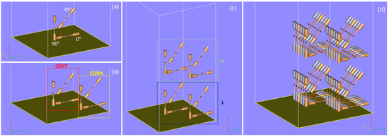 Figure 1. Design of the build aimed at investigating: (a) orientation, (b) location in the layer, (c) height, and (d) complete build design.

Table 1.
Factors and levels of the DOE.
Table 1.
Factors and levels of the DOE.
| Factor | Levels | Values |
|---|---|---|
| Diameter size | 3 | 1.0; 1.5; 2.0 mm |
| Sample orientation | 3 | 0°; 45°; 90° |
| Zone | 2 | CENT; CORN |
| Height | 2 | H; L |
2.2. Material
Ti6Al4V plasma atomised powder, with spherical morphology, was used to manufacture the specimens of this study. The powder properties in terms of flowability [37], apparent density [38], particle size distribution [39], and chemical composition [40] are reported in [41].
2.3. Design of the Tensile Specimen
The tensile specimen investigated in this study shows the same geometry of the trusses composing an octet–truss structure. The gauge length is composed by a circular section having different diameters d (equal to 1, 1.5, and 2 mm). The length of the calibrated section is not particularly important for this study: it must be sufficiently representative for the analysis, and for this reason, a length of 25 mm was chosen.
The specimen geometry is shown in Figure 2. The computer-aided design software used for the drawing of the lattice structures was Solid Edge (Siemens PLM Software, Plano, TX, United States). The geometry of the specimen was modelled in two separate files, one representing the specimen heads and the other one representing the gauge length, in order to assign different process themes to the heads and to the gauge length as will be described afterward.
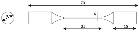
Figure 2.
Truss specimen geometry (dimensions in mm) [41].
2.4. Job Preparation
The CAD model of the specimen was transmitted to Magics (Materialise NV, Leuven, Belgium) software for positioning on the building platform. Also, for supports generation, Magics Materialise software was used.
Support structures, required in the EBM process to improve the heat energy dissipation and to reduce the geometric defects, such as warping or curling, were generated only for the specimen heads. The length of the supports was 30 mm, while the distance between them was 3 mm, as shown in Figure 3.
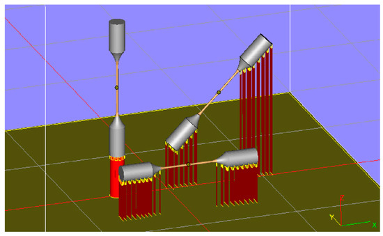
Figure 3.
Wafer supports in the job preparation [41].
The geometry of the specimens was scaled according to the scale factors suggested by the machine manufacturer, which were 1.0092 for the x and y directions and 1.0132 for the z direction. These factors are optimised for the EBM manufacturing of massive components in order to consider the thermal shrinkage occurring after melting.
Afterward, the “Materialise Build Processor” was used for slicing STL files into 2D-compressed layer files: a sliced layer thickness of 50 μm was chosen. The slicing output is the ARCAM Build Processor (ABP) file, which contains all the information needed to perform a build in an A2X EBM machine (ARCAM AB, Molndal, Sweden): in the ABP file, it is possible to visualise the layers of the parts and to verify, layer by layer, the building of the part. The process parameters were imposed through the “EBM control 3.2” software (ARCAM AB, Molndal, Sweden) embedded in the EBM system. The automatic operating mode of the EBM system was chosen, and the following sets of process parameters for the Ti6Al4V alloy were used:
- “Ti6Al4V-PreHeat-50 μm”: process theme that controls the preheating of the whole powder bed.
- “Ti6Al4V-Melt-50 μm”: process theme used to melt the solid part of the specimen (heads).
- “Ti6Al4V-Net-50 μm”: process theme used to melt the lattice part of the specimen (gauge length).
- “Ti6Al4V-Wafer-50 μm”: process theme used to melt the wafer supports.
For all the themes, a layer thickness of 50 μm and a line offset of 0.1 mm were set. These build themes vary electron beam parameters in a controlled sequence throughout the build according to algorithms developed by the manufacturer in an effort to achieve parts with consistent properties. Since the algorithm is protected by copyright, beam current, and beam speed time-dependent diagrams are not provided to the users.
2.5. Specimens Manufacturing
The specimens were produced by using the A2X EBM machine (ARCAM AB, Molndal, Sweden), with a built chamber able to withstand temperatures up to 1100 °C, making it suitable to process material requiring elevated process temperatures for both production and materials R&D. In the A2X 3D printing system (ARCAM AB, Molndal, Sweden), the EBM process was carried out in vacuum (5 × 10⁻⁶ mbar in the column).
Once the job was completed, the build cake was moved directly to the powder recovery system (PRS) to remove and recover the sintered powder from around the specimens (Figure 4a). Then, the recovered powder was sieved and saved for future use. Once the PRS cleaning operation was completed, the wafer support structures were removed. The 3D-printed specimens are shown in Figure 4b–d, before support removal.
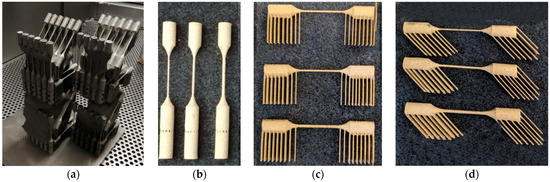
Figure 4.
(a) Post-running operation—depowdering of specimens in PRS; (b) Truss specimens oriented at 90°; (c) Truss specimens oriented at 0°; (d) Truss specimens oriented at 45°.
2.6. Specimen Measuring
Once the specimens were created, an image processing approach was used to take their measurements, following a procedure presented in [41]. Utilising a stereomicroscope with a 10× magnification, the SMZ800 (Nikon corporation, Tokyo, Japan), the specimen photographs were captured. For each specimen, a local reference system was defined as follows: x-axis along the longitudinal direction of the sample, y-axis parallel to the short dimension of wafer supports, and z-axis perpendicular to the plane x-y. The local reference systems for the samples oriented at 0°, 45°, and 90° are shown, respectively, in Figure 5a–c. For each specimen, two images were captured, the first observing the specimen from the local z-axis direction and the second observing the specimen from the local y-axis direction. The first image was used to measure the diameter named D1, while the second image was used to measure the diameter called D2, as shown in the sketches of Figure 5, for each specimen orientation. All the captured images were processed in the Matlab Image Toolbox, following the steps below: first, unnecessary portions were removed from the image so that elaboration could be carried out solely on the specimen area; second, the image was transformed to greyscale and binarised to clearly separate the specimen from the background. Then, the coordinates of the points denoting the specimen’s boundary were located and exported. Figure 6 shows the results coming from each step of the image elaboration.
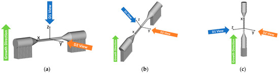
Figure 5.
Reference direction for image acquisition: (a) 0° oriented sample, (b) 45° oriented sample, (c) 90° oriented sample.
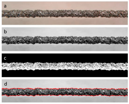
Figure 6.
Image elaboration sequence: (a) cutting of unused areas; (b) conversion to grayscale; (c) binarisation; (d) profile identification [41].
Finally, the exported coordinates were elaborated through Microsoft Excel to extract the average diameter of each specimen along the specific observation direction. For each specimen, the diameter DM (measured diameter) was computed as an average between diameter D1 and diameter D2.
3. Results
The produced samples were analysed through a scanning electron microscope. As visible in Figure 7, the truss surface was rather irregular. In particular, in the trusses oriented at 0°, the lower part of the surface presented an elevated roughness given by powder particles that were only partially melted and remained bonded to the surface. On the contrary, the upper part of the surface was smoother since the number of unmelted powder particles was reduced. This difference between the two specimen surfaces was less pronounced for the 45° specimen and almost completely absent for the 90° specimen.
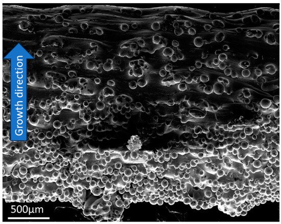
Figure 7.
Micrography of a truss (2 mm diameter, 0° oriented sample).
The results of the samples’ measuring, in terms of average diameter (DM), coefficient of variation (CoV), and the error (err) defined as the difference between the average diameter (DM) and the nominal diameter (DN), are reported in Table 2. In each row, the results are grouped for samples with the same location in the layer, height, and orientation. Columns are related to the different investigated truss diameters.
Table 2.
Results of specimens’ measuring.
The objective of this study is to evaluate the effects of some job parameters on the geometric accuracy of Ti6Al4V trusses manufactured by EBM technology. In particular, the project parameters taken into account in this investigation were sample orientation, height and zone in the build chamber, and truss diameter size. The statistical analysis carried out in this study consists of the analysis of variance (ANOVA) aimed at establishing the significance of the effect of the above-mentioned parameters on two output variables:
- The error parameter err, defined as the difference between the measured diameter (DM) and the nominal diameter (DN) of the trusses.Err = DM − DN
- The ovalisation ratio Or of the trusses, defined as the absolute value of the difference between 1 and the ratio of diameter D1 and D2.
An analysis of variance was carried out on data representing the error between measured and nominal diameter size and the ovalisation ratio of the trusses in order to verify the significance of the following factors: sample orientation, diameter size of the trusses, height, and zone in the build envelope. In Table 3, the results of ANOVA for the err variable are reported. In that table, the degree of freedom (DF) represent the number of elements used for each calculation, the adjusted sum of squares (Adj SS) indicates the quantity of additional variation in the response for a term, the adjusted mean square (Adj MS) is the Adj SS divided by the DF, the F-value and the P-value are two statistical terms that indicate how much a term is significant for the model. The results demonstrate the significance of three factors, i.e., zone, sample orientation, and diameter. In fact, for these parameters, the P-value was less than 5%, the value generally taken as the reference threshold.
Table 3.
Analysis of variance for the “err” variable.
The analysis of the main effect plots (Figure 8) highlights that all the trusses presented a diameter lower than the nominal one. Nevertheless, as far as the orientation is concerned, good compliance was found between the measured diameter size and nominal value for the trusses oriented at 0° and a significant increase in the error for the trusses oriented at 45° and 90°. Moreover, as far as the diameter size is concerned, the main effect plots show that, for the trusses with 1 mm of diameter size, the measured diameter is closer to the nominal one with respect to the trusses having 1.5 mm and 2 mm of diameter size. An increase in the error is found between the corner zone (CORN) and the central zone (CENT), while a slight error decrease is measured between high-level H (z1 = 140 mm) and low-level L (z2 = 20 mm).
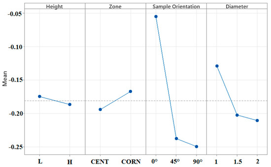
Figure 8.
Main effect plot for err variable (mean in mm).
The results of ANOVA for the ovalisation are reported in Table 4. The analysis demonstrates the significance of two factors: sample orientation and diameter size.
Table 4.
Analysis of variance for the Or variable.
The analysis of the main effect plots (Figure 9) highlights low ovalisation for the trusses oriented at 45° and 90° and a significant increase in the ovalisation for the trusses oriented at 0°.
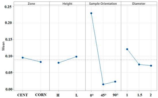
Figure 9.
Main effect plot for Or variable.
Moreover, the main effect plots show even an inversely proportional ovalisation of the trusses related to the diameter size. The main effect plots point out that the ovalisation is not significantly influenced by the zone and by the height.
4. Discussion
By analysing the results, a first consideration that can be drawn is that all the trusses have an actual diameter lower than the nominal one, in agreement with the findings of Bellini et al. [41] and Suard et al. [42]. This fact can be explained by a mismatching between the shrinkage coefficients used and the optimal ones (actually unknown). Indeed, ARCAM-recommended scale factors are optimised for EBM manufacturing of massive components processed using the melt process theme instead of the net process theme used in this study for the trusses. Moreover, fixed scale factors do not take into account the different thermal shrinkage that occurs in different positions due to a non-identical thermal history experienced by the material.
According to [32], all truss members with an orientation different from 90° fabricated with the default process parameters provided by the manufacturer Arcam were undersized. This issue is exacerbated as the orientation decreases from 90° to 0°. The reason for this inaccuracy was observed to be an excessive beam energy density at regions in proximity to negative surfaces. This resulted in part distortion that compromised the powder deposition and melting stages in the subsequent layers. A strong dependence of the residual stresses and the yield strength on the building orientation was also found in [43,44], respectively.
In this case, the most favourable orientations for heat dissipation are those at 90° and 45°, as in both cases, the presence of already melted material in the underlying layers guarantees a preferential route for heat dissipation.
In any case, although the trusses at 0° are the ones with the worst heat dissipation, their diameter is closer to the nominal one with respect to the diameters of the trusses grown at 45° and 90°. This behaviour is due to a lower heat exchange for the trusses grown at 0° that produce larger melting pools and, consequently, a more significant part of powder solidification (metal oversize), recovering the error in dimensional accuracy.
For 0° trusses, the metal oversize is mainly generated in the direction of the supports, which also explains the high ovality found in the specimens for these trusses compared to those oriented at 45° and at 90°. Such results were in agreement with [45]. A possible explanation for this phenomenon can be found by considering the heat transfer during the melting phase of the EBM process. For horizontal trusses, since the sintered powder has a lower thermal conductivity with respect to the melted area, a heat accumulation resulted in an over-melted zone that increases the ovalisation, as found in [46].
The heat dissipation is inversely proportional to the diameter of the truss. This result can be explained by the fact that, in the truss with 1 mm of diameter, there is a greater concentration of heat energy as compared to the trusses with bigger diameters. For this reason, larger melting pools are generated and, consequently, larger amounts of sintered powders which led to a truss diameter size close to the nominal size if compared to the trusses at 1.5 mm and 2 mm diameter sizes.
The heat exchange is proportional to the material density (better behaviour through solidified components or start plate, worst behaviour through sintered powder and wafer supports). For this reason, a slightly lower deviation from the nominal value (lower error) was found at level L (z1 = 20 mm), where the trusses’ supports are in contact with the stainless steel start plate, while at level H (z2 = 140 mm) the supports end in the almost-sintered powder.
5. Conclusions
The mechanical properties of the produced lattice structures may be different than the target values. This is caused by a mismatch between the nominal dimension of the trusses and the actual ones, as demonstrated in a previous article. In the present paper, small trusses, representing those of lattice structures, were produced through the electron beam melting (EBM) process to analyse the effect of some process parameters on their diameter. In particular, they were built considering three different growth directions in the machine manufacturing chamber, which coincide with the direction of the trusses in an actual lattice structure. Moreover, three distinct diameters were taken into consideration too, namely 1 mm, 1.5 mm, and 2 mm, as well as four diverse positions in the build chamber. Then, the diameters of the produced samples were evaluated through a methodology presented in a previous paper, and the obtained results were statistically analysed thanks to ANOVA.
The performed analyses determined that the geometrical mismatch between the nominal and the actual diameters was mainly affected by two parameters: the orientation in the building chamber and the nominal diameter and, to a lesser extent, from the zone on the working surface. An average diameter reduction of 0.05 mm was found for the trusses with a 0° orientation, while this value rose to 0.24 mm and 0.25 mm for the trusses with an orientation of 45° and 90°, respectively. Moreover, the circularity of the truss sections was examined too, and a certain ovalisation level was found, especially for the specimens oriented at 0°, being the diameter evaluated in a plane parallel to the growth direction larger than that measured in an orthogonal plane. In fact, the mean ovalisation of the trusses oriented at 0° was 0.23, while for the others it was about 0.05. The found geometrical and dimensional unconformities were due to an excessive beam energy density at regions in proximity to negative surfaces, given by heat dissipation, that in the 0° case was the worst. In this occurrence, larger melting pools were created and, consequently, the section resulted ovalised. This affected the measurement of the diameters too, whose average value was closer to the nominal value thanks to the elongation in the build direction. Moreover, the melting pool effect was higher for smaller diameters.
The results of this work are useful for the realisation of lattice parts, from designing to manufacturing. In fact, in future works, the correlation between the analysed process parameters and the mechanical properties of the produced trusses will be presented, and this information can be used to design lattice parts with complex shapes. The design efficiency can be further improved by adopting homogenisation techniques, suitable to reduce the calculation time.
Author Contributions
All authors equally contributed to this article. Methodology: C.B., R.B., F.D.C., V.D.C., S.F., F.I., C.P. and L.S.; Investigation: C.B., R.B., F.D.C., V.D.C., S.F., F.I., C.P. and L.S.; Writing—original draft: C.B., R.B., F.D.C., V.D.C., S.F., F.I., C.P. and L.S. All authors have read and agreed to the published version of the manuscript.
Funding
This research was supported by POR FESR Lazio 2014–2020, Strategic Projects—AoS Aerospace (AMHybridStructures project, 28143, rif. G06734/2020).
Data Availability Statement
The data presented in this study are available upon request from the corresponding author. The data are not publicly available due to privacy restrictions.
Conflicts of Interest
The authors declare no conflict of interest.
References
- Uriondo, A.; Esperon-Miguez, M.; Perinpanayagam, S. The present and future of additive manufacturing in the aerospace sector: A review of important aspects. Proc. Inst. Mech. Eng. Part G J. Aerosp. Eng. 2015, 229, 2132–2147. [Google Scholar] [CrossRef]
- Brackett, D.; Ashcroft, I.; Hague, R. Topology optimisation for additive manufacturing. In Proceedings of the Solid Freeform Fabrication Symposium, Austin, TX, USA, 8–10 August 2011; pp. 348–362. [Google Scholar]
- Bourell, D.; Kruth, J.P.; Leu, M.; Levy, G.; Rosen, D.; Beese, A.M.; Clare, A. Materials for additive manufacturing. CIRP Ann. Manuf. Technol. 2017, 66, 659–681. [Google Scholar] [CrossRef]
- Kotz, F.; Arnold, K.; Bauer, W.; Schild, D.; Keller, N.; Sachsenheimer, K.; Nargang, T.M.; Richter, C.; Helmer, D.; Rapp, B.E. Three-dimensional printing of transparent fused silica glass. Nature 2017, 544, 337–339. [Google Scholar] [CrossRef]
- Herzog, D.; Seyda, V.; Wycisk, E.; Emmelmann, C. Additive manufacturing of metals. Acta Mater. 2016, 117, 371–392. [Google Scholar] [CrossRef]
- Olakanmi, E.O.T.; Cochrane, R.F.; Dalgarno, K.W. A review on selective laser sintering/melting (SLS/SLM) of aluminium alloy powders: Processing, microstructure, and properties. Prog. Mater. Sci. 2015, 74, 401–477. [Google Scholar] [CrossRef]
- Cantaboni, F.; Ginestra, P.; Tocci, M.; Avanzini, A.; Ceretti, E.; Pola, A. Compressive behavior of Co-Cr-Mo radially graded porous structures under as-built and heat-treated conditions. Fratt. Integr. Strutt. 2022, 16, 490–504. [Google Scholar] [CrossRef]
- Parthasarathy, J.; Starly, B.; Raman, S.; Christensen, A. Mechanical evaluation of porous titanium (Ti6Al4V) structures with electron beam melting (EBM). J. Mech. Behav. Biomed. Mater. 2010, 3, 249–259. [Google Scholar] [CrossRef]
- Baudana, G.; Biamino, S.; Ugues, D.; Lombardi, M.; Fino, P.; Pavese, M.; Badini, C. Titanium aluminides for aerospace and automotive applications processed by Electron Beam Melting: Contribution of Politecnico di Torino. Met. Powder Rep. 2016, 71, 193–199. [Google Scholar] [CrossRef]
- Zhang, X.; Leary, M.; Tang, H.; Song, T.; Qian, M. Selective electron beam manufactured Ti-6Al-4V lattice structures for orthopedic implant applications: Current status and outstanding challenges. Curr. Opin. Solid State Mater. Sci. 2018, 22, 75–99. [Google Scholar] [CrossRef]
- Maskery, I.; Aboulkhair, N.T.; Aremu, A.O.; Tuck, C.J.; Ashcroft, I.A.; Wildman, R.D.; Hague, R.J.M. A mechanical property evaluation of graded density Al-Si10-Mg lattice structures manufactured by selective laser melting. Mater. Sci. Eng. A 2016, 670, 264–274. [Google Scholar] [CrossRef]
- Bellini, C.; Borrelli, R.; Di Cocco, V.; Franchitti, S.; Iacoviello, F.; Mocanu, L.P.; Sorrentino, L. Failure energy and stiffness of titanium lattice specimens produced by electron beam melting process. Mater. Des. Process. Commun. 2021, 3, e268. [Google Scholar] [CrossRef]
- Gong, X.; Anderson, T.; Chou, K. Review on powder-based electron beam additive manufacturing technology. Manuf. Rev. 2014, 1, 2. [Google Scholar] [CrossRef]
- Körner, C. Additive manufacturing of metallic components by selective electron beam melting—A review. Int. Mater. Rev. 2016, 61, 361–377. [Google Scholar] [CrossRef]
- Borrelli, R.; Franchitti, S.; Pirozzi, C.; Carrino, L.; Nele, L.; Polini, W.; Sorrentino, L.; Corrado, A. Ti6Al4V Parts Produced by Electron Beam Melting: Analysis of Dimensional Accuracy and Surface Roughness. J. Adv. Manuf. Syst. 2020, 19, 107–130. [Google Scholar] [CrossRef]
- Murr, L.; Esquivel, E.; Quinones, S.; Gaytan, S.; Lopez, M.; Martinez, E.; Medina, F.; Hernandez, D.; Martinez, J.; Stafford, S.; et al. Microstructures and mechanical properties of electron beam-rapid manufactured Ti-6Al-4V biomedical prototypes compared to wrought Ti-6Al-4V. Mater. Charact. 2009, 60, 96–105. [Google Scholar] [CrossRef]
- Koike, M.; Martinez, K.; Guo, L.; Chahine, G.; Kovacevic, R.; Okabe, T. Evaluation of titanium alloy fabricated using electron beam melting system for dental applications. J. Mater. Process. Technol. 2011, 211, 1400–1408. [Google Scholar] [CrossRef]
- Svensson, M.; Ackelid, U. Titanium alloys manufactured with electron beam melting mechanical and chemical properties. Medical Device Materials. In Proceedings of the Materials and Processes for Medical Devices Conference, Minneapolis, MN, USA, 10–12 August 2009; pp. 189–194. [Google Scholar]
- Gaytan, S.M.; Murr, L.E.; Hernandez, D.H.; Martinez, E.; Quinones, S.A.; Medina, F.; Wicker, R.B. Structure-property-process optimisation in the rapid-layer manufacturing of Ti-6A1-4V components by electron beam melting. In Proceedings of the TMS 2009-138th Annual Meeting and Exhibition 2009, San Francisco, CA, USA, 15–19 February 2009; pp. 363–369. [Google Scholar]
- Koike, M.; Greer, P.; Owen, K.; Lilly, G.; Murr, L.E.; Gaytan, S.M.; Martinez, E.; Okabe, T. Evaluation of Titanium Alloys Fabricated Using Rapid Prototyping Technologies—Electron Beam Melting and Laser Beam Melting. Materials 2011, 4, 1776–1792. [Google Scholar] [CrossRef]
- Bellini, C.; Borrelli, R.; Di Cocco, V.; Franchitti, S.; Iacoviello, F.; Sorrentino, L. Bending properties of titanium lattice structures produced by electron beam melting process. Fatigue Fract. Eng. Mater. Struct. 2021, 44, 1961–1970. [Google Scholar] [CrossRef]
- Bellini, C.; Borrelli, R.; Di Cocco, V.; Franchitti, S.; Iacoviello, F.; Sorrentino, L. Titanium lattice structures manufactured by EBM process: Effect of skin material on bending characteristics. Eng. Fract. Mech. 2022, 260, 108180. [Google Scholar] [CrossRef]
- Cansizoglu, O.; Harrysson, O.; Cormier, D.; West, H.; Mahale, T. Properties of Ti–6Al–4V non-stochastic lattice structures fabricated via electron beam melting. Mater. Sci. Eng. A 2008, 492, 468–474. [Google Scholar] [CrossRef]
- Sepe, R.; De Luca, A.; Giannella, V.; Borrelli, R.; Franchitti, S.; Di Caprio, F.; Caputo, F. Influence of dimension, building position, and orientation on mechanical properties of EBM lattice Ti6Al4V trusses. Int. J. Adv. Manuf. Technol. 2022, 122, 3183–3198. [Google Scholar] [CrossRef]
- Epasto, G.; Palomba, G.; D’Andrea, D.; Guglielmino, E.; Di Bella, S.; Traina, F. Ti-6Al-4V ELI microlattice structures manufactured by electron beam melting: Effect of unit cell dimensions and morphology on mechanical behaviour. Mater. Sci. Eng. A 2019, 753, 31–41. [Google Scholar] [CrossRef]
- Gong, H.; Rafi, K.; Starr, T.; Stucker, B. The Effects of Processing Parameters on Defect Regularity in Ti-6Al-4V parts Fabricated by Selective Laser Melting and Electron Beam Melting. In Proceedings of the 24th Annual International Solid Freeform Fabrication Symposium, Austin, TX, USA, 8–10 August 2011. [Google Scholar]
- Pirozzi, C.; Franchitti, S.; Borrelli, R.; Diodati, G.; Vattasso, G. Experimental Study on the Porosity of Electron Beam Melting-Manufactured Ti6Al4V. J. Mater. Eng. Perform. 2019, 28, 2649–2660. [Google Scholar] [CrossRef]
- Pirozzi, C.; Franchitti, S.; Borrelli, R.; Caiazzo, F.; Alfieri, V.; Argenio, P. Study on the Factors Affecting the Mechanical Behavior of Electron Beam Melted Ti6Al4V. J. Mater. Eng. Perform. 2017, 26, 4491–4499. [Google Scholar] [CrossRef]
- Gong, H.; Rafi, K.; Gu, H.; Ram, G.D.J.; Starr, T.; Stucker, B. Influence of defects on mechanical properties of Ti–6Al–4V components produced by selective laser melting and electron beam melting. Mater. Des. 2015, 86, 545–554. [Google Scholar] [CrossRef]
- Liu, L.; Kamm, P.; García-Moreno, F.; Banhart, J.; Pasini, D. Elastic and failure response of imperfect three-dimensional metallic lattices: The role of geometric defects induced by Selective Laser Melting. J. Mech. Phys. Solids 2017, 107, 160–184. [Google Scholar] [CrossRef]
- Lozanovski, B.; Leary, M.; Tran, P.; Shidid, D.; Qian, M.; Choong, P.; Brandt, M. Computational modelling of strut defects in SLM manufactured lattice structures. Mater. Des. 2019, 171, 107671. [Google Scholar] [CrossRef]
- Smith, C.; Derguti, F.; Nava, E.H.; Thomas, M.; Tammas-Williams, S.; Gulizia, S.; Fraser, D.; Todd, I. Dimensional accuracy of Electron Beam Melting (EBM) additive manufacture with regard to weight optimized truss structures. J. Mater. Process. Technol. 2016, 229, 128–138. [Google Scholar] [CrossRef]
- Sing, S.L.; Wiria, F.E.; Yeong, W.Y. Selective laser melting of lattice structures: A statistical approach to manufacturability and mechanical behavior. Robot. Comput. Integr. Manuf. 2018, 49, 170–180. [Google Scholar] [CrossRef]
- Di Caprio, F.; Franchitti, S.; Borrelli, R.; Bellini, C.; Di Cocco, V.; Sorrentino, L. Ti-6Al-4V Octet-Truss Lattice Structures under Bending Load Conditions: Numerical and Experimental Results. Metals 2022, 12, 410. [Google Scholar] [CrossRef]
- Yu, Z.; Ding, D.; Pan, Z.; Li, H.; Lu, Q.; Fang, X. A strut-based process planning method for wire arc additive manufacturing of lattice structures. J. Manuf. Process. 2021, 65, 283–298. [Google Scholar] [CrossRef]
- Veiga, F.; Suárez, A.; Aldalur, E.; Goenaga, I.; Amondarain, J. Wire Arc Additive Manufacturing Process for Topologically Optimized Aeronautical Fixtures. 3D Print. Addit. Manuf. 2023, 10, 23–33. [Google Scholar] [CrossRef]
- ASTM B213; Standard Test Methods for Flow Rate of Metal Powders Using the Hall Flowmeter Funnel. ASTM: West Conshohocken, PA, USA, 2020. [CrossRef]
- ASTM B212; Standard Test Method for Apparent Density of Free-Flowing Metal Powders Using the Hall Flowmeter Funnel. ASTM: West Conshohocken, PA, USA, 2021. [CrossRef]
- ASTM B214; Standard Test Method for Sieve Analysis of Metal Powders. ASTM: West Conshohocken, PA, USA, 2022. [CrossRef]
- ASTM F2924; Standard Specification for Additive Manufacturing Titanium-6 Aluminum-4 Vanadium with Powder Bed Fusion. ASTM: West Conshohocken, PA, USA, 2021. [CrossRef]
- Bellini, C.; Borrelli, R.; Di Caprio, F.; Di Cocco, V.; Franchitti, S.; Iacoviello, F.; Sorrentino, L. An Innovative Method to Analyse the Geometrical Accuracy of Ti6Al4V Octet-Truss Lattice Structures. Materials 2023, 16, 2372. [Google Scholar] [CrossRef]
- Suard, M.; Martin, G.; Lhuissier, P.; Dendievel, R.; Vignat, F.; Blandin, J.-J.; Villeneuve, F. Mechanical equivalent diameter of single struts for the stiffness prediction of lattice structures produced by Electron Beam Melting. Addit. Manuf. 2015, 8, 124–131. [Google Scholar] [CrossRef]
- Fiorentin, F.; Oliveira, B.; Pereira, J.; Correia, J.; de Jesus, A.M.; Berto, F. Fatigue Behavior of Metallic Components Obtained by Topology Optimization for Additive Manufacturing. Fratt. Integr. Strutt. 2021, 15, 119–135. [Google Scholar] [CrossRef]
- Andreacola, F.R.; Capasso, I.; Pilotti, L.; Brando, G. Influence of 3D-printing parameters on the mechanical properties of 17-4PH stainless steel produced through Selective Laser Melting. Fratt. Integr. Strutt. 2021, 15, 282–295. [Google Scholar] [CrossRef]
- Suard, M.; Lhuissier, P.; Dendievel, R.; Blandin, J.-J.; Vignat, F.; Villeneuve, F. Towards stiffness prediction of cellular structures made by electron beam melting (EBM). Powder Met. 2014, 57, 190–195. [Google Scholar] [CrossRef]
- Del Guercio, G.; Galati, M.; Saboori, A.; Fino, P.; Iuliano, L. Microstructure and Mechanical Performance of Ti–6Al–4V Lattice Structures Manufactured via Electron Beam Melting (EBM): A Review. Acta Met. Sin. (English Lett.) 2020, 33, 183–203. [Google Scholar] [CrossRef]


Disclaimer/Publisher’s Note: The statements, opinions and data contained in all publications are solely those of the individual author(s) and contributor(s) and not of MDPI and/or the editor(s). MDPI and/or the editor(s) disclaim responsibility for any injury to people or property resulting from any ideas, methods, instructions or products referred to in the content. |
© 2023 by the authors. Licensee MDPI, Basel, Switzerland. This article is an open access article distributed under the terms and conditions of the Creative Commons Attribution (CC BY) license (https://creativecommons.org/licenses/by/4.0/).