1. Introduction
Climate change is an urgent and formidable challenge facing human society today. Carbon dioxide (CO
2), as an inevitable outcome of industrial society modernization, has caused a serious greenhouse effect; therefore, reducing carbon-based gas emissions has become a global goal. In September 2020, China’s president Xi Jinping proposed the “dual carbon” strategy at the 75th United Nations General Assembly, which aims to reach the peak of CO
2 emissions before 2030 and achieve carbon neutrality before 2060 [
1,
2]. At present, the carbon-emitting industries of China are making efforts to develop decarbonization technologies, aiming to achieve carbon reduction transformation before the deadline set by the “dual carbon” targets. In this regard, the steel industry consumes approximately 13% of the national energy, while its carbon emissions account for around 15% of the total national emissions. Therefore, as a high-energy and high-emission sector, the steel industry urgently needs to undergo green and low-carbon transformation [
3,
4,
5].
The blast furnace (BF) and basic oxygen furnace (BOF) process is still the main process of iron and steel production in China, in which more than 90% of the CO
2 emission and 70% of the energy consumption are from the BF ironmaking process (sintering, coking, and BF). The entire process relies on reducing gas CO generated by coke for the reduction of iron oxides, and the resulting CO
2 is directly emitted into the atmosphere. Therefore, implementing low-carbon transformation in the BF ironmaking process becomes a key step in reducing emissions in the steel industry [
6,
7,
8,
9]. The traditional BF, due to its advantages such as high production capacity, efficiency, low cost, and mature technology, will remain the mainstream steel production process for a considerable period of time in the future. After extensive research, metallurgists believe that “hydrogen metallurgy”, which utilizes H
2 for reduction, is the primary direction for green and low-carbon development in the steel industry. It is expected that the proportion of hydrogen metallurgy will significantly increase year by year before 2060, becoming the mainstream process for reducing CO
2 emissions [
10,
11]. Currently, many steel companies both domestically and internationally have made arrangements for hydrogen metallurgy, forming two feasible technical pathways: the short-process route of green hydrogen direct reduction with an electric arc furnace (EAF) and the long-process route of conventional BF reconstitution with hydrogen. Among them, the EAF process utilizing scrap steel or direct reducing iron (DRI) produced by hydrogen-based process as raw materials seems to be the most mature technology route to date, capable of reducing 95% of CO
2 emissions. However, it is limited by scarce high-grade iron ore resources [
12]. Considering the existing stock of BFs, it is anticipated that BF ironmaking will remain the primary ironmaking method in China in the short term. The hydrogen-rich ironmaking process in BFs has become more mature through continuous research, but there are significant differences between hydrogen-based and carbon-based gas reduction conditions. The hydrogen content in BFs remains at a low level, not exceeding 15%, greatly limiting the extent of CO
2 emission reduction in BFs [
11]. Exploring new methods of a high proportion of hydrogen to break through the CO
2 emission limit requires technical reconstruction of the hydrogen-rich process and proposing new plans to provide theoretical and technical support for achieving the ultimate emission reduction in ironmaking.
Northeastern University has studied the key factors limiting emissions reduction in BFs and proposed a new ironmaking process of a reduction smelting furnace (RSF) that is hydrogen-rich and utilizes pure oxygen and carbon recycle (Hy-O-CR) [
13]. They have also developed a mass–energy balance model for the new process in a previously published paper of Ref. [
14]. By upgrading technologies such as injecting high-temperature reducing gas through the upper shaft tuyere and cooperating to control the gas distribution ratio between the shaft zone and the hearth zone, the technical bottleneck that the metallization rate in the upper part of the traditional BF is less than 70% has been solved. The two technologies of decarbonization of the top gas and hydrogen production by electrolysis of water are reconstructed to form a new technology of hydrogen-rich self-circulation of decarbonized gas. This technology involves decarbonized gas and green hydrogen being mixed, heated, and injected into RSF through a specific tuyere structure, which is a new technique that can significantly reduce carbon emissions in the ironmaking process.
The process of RSF with Hy-O-CR is a transformation and upgrade based on processes such as Fink [
15], NKK [
16], ULCOS top gas recycling blast furnace process [
17], and shaft injection blast furnace [
18,
19,
20]. The RSF process of full oxygen injection instead of the BF process with hot air injection can avoid the problem of nitrogen (N
2) accumulation in the top gas circulation process cycle. The oxygen blast furnace (OBF) process often encounters the problem of excessive cooling in the upper zone [
21,
22]. Although injecting a high proportion of hydrogen-based gas from the shaft tuyere can significantly reduce carbon emissions, the endothermic reaction during the reduction with hydrogen-based gas exacerbates this problem [
23]. Mehdi [
24] addressed the issue of insufficient heat in the upper zone by adding auxiliary fuel combustion to release heat. Additionally, high-temperature reducing gases were injected into the furnace shaft to promote the reduction of FeO. The authors proposed a new process that also utilizes the injecting of a high-proportion hydrogen-based gas into the furnace shaft to achieve maximum emission reduction. The issue of insufficient heat in the upper zone was solved by excess high-temperature gas being injected into the furnace shaft, which significantly increased the metallization rate in the upper zone and minimized direct reduction in the lower zone. The heat generated from the combustion of auxiliary fuel sources (such as natural gas, coke oven gas, coal or coke, etc.) was sufficient to meet its internal heat consumption for direct reduction in the lower zone, and the excess gas flowed upstream and carried the waste heat from the lower zone to the upper furnace shaft area. This inevitably led to a decrease in the gas utilization rate inside the furnace, but the gas generated from the combustion of auxiliary fuel can be fully utilized by means of the top gas circulation, which improves the overall gas utilization.
The top gas circulation model is a sub-module of the new RSF process. It is a new technology for hydrogen-rich recycling of the top gas treated by CO
2 removal equipment. The main components of the circulating gas are CO and H
2. Considering the carburization phenomenon of the mixture of CO and H
2 in the heating process, the circulating gas process has been modified and upgraded in order to better fit the new process. Mapelli C [
25] researched the future scenarios for reducing emissions and consumption in the Italian steelmaking industry. The amount of CO
2 emissions, water and electricity consumption, and soil exploitation of the main steel production routes (integrated cycle, scrap recycling, and direct reduction) were analyzed applying three possible future scenarios: use of carbon capture and storage (CCS); use of green hydrogen in substitution of natural gas; and use of biomethane. Foo S Y [
26] proposed that introducing a certain amount of CO
2 can suppress the carburization reaction of CO and H
2 in the furnace. Therefore, in this model, the CO
2 removal rate of the top gas is not 100%, and the remaining CO
2 is introduced into the furnace along with CO and H
2. This not only inhibits the carburization phenomenon of the circulating gas but also reduces the decarburization cost. By combining CO
2 capture, utilization, and storage technologies (CCUS), the overall process achieves maximum emission reduction. In addition, in order to fully utilize the chemical heat of the top gas, a certain proportion of the top gas is used as the combustion gas source to heat and elevate the temperature of the circulating reducing gas injected into the furnace shaft. The electrolytic water device is used to supply the required H
2 for the hydrogen-rich process of reducing gas, and the byproduct oxygen (O
2) can also serve as a direct source of O
2 injected through the lower tuyere into the RSF [
27]. Although the power consumption and cost of the process flow after using electrolytic water for hydrogen production are higher compared to traditional BFs, with the reduction of the cost of hydrogen production, the optimization of the process, and the development of CCUS technology in the future, the new process will have a very broad development prospect in the future low-carbon era.
2. Model of RSF with Hy-O-CR
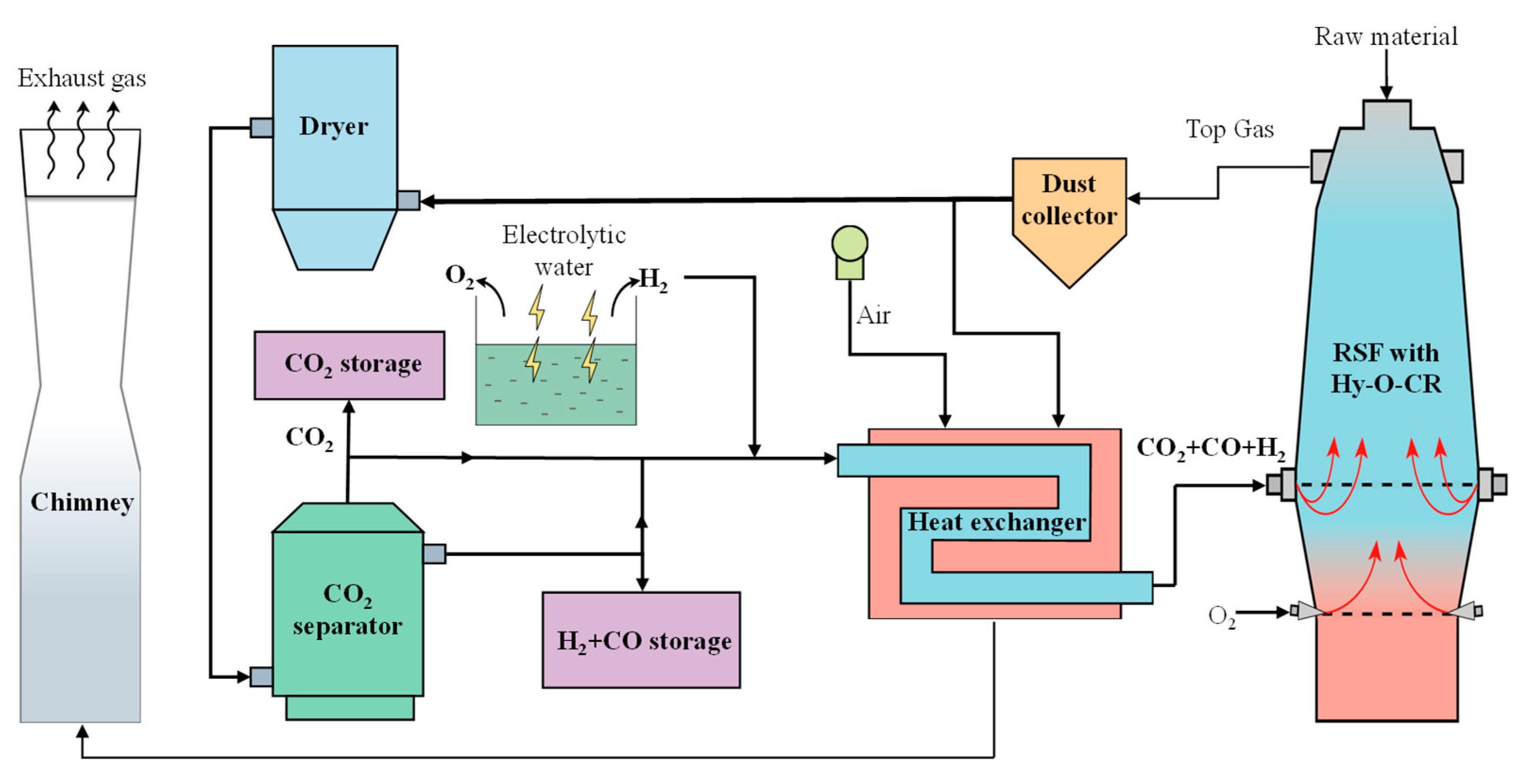
The schematic diagram of the new process of RSF with Hy-O-CR is shown in
Figure 1. The top gas produced in the RSF is purified by a dust collector and then divided into two parts, of which a small part of the gas is used as a combustion gas source for combustion and heating, and most of the gas goes into the dryer for H
2O removal and the CO
2 separator for CO
2 separation. The removed H
2O can be recycled and used as a water source for the electrolytic water process. The extracted CO
2 enters a CO
2 storage tank for enhanced oil recovery or chemical raw materials. The resulting reducing gas is divided into two parts for further treatment, a small part of which is directly stored in the gas tank without heating as a backup gas source. In addition, most of the reducing gas (CO, H
2, and a small amount of CO
2) is mixed with a certain amount of hydrogen, enters into the heating exchanger, and is heated to form high-temperature (>900 °C) reducing gas, which is injected into the RSF from the furnace shaft tuyere to achieve decarbonization reduction gas recycling. The reason for not fully removing CO
2 is that the inclusion of a certain amount of CO
2 effectively prevents carburization reactions during the heating process [
28,
29]. The electrolytic water device supplies sufficient H
2, which is also supplemented into the heat exchanger. The byproduct O
2 can be injected into the lower tuyere for full oxygen injecting.
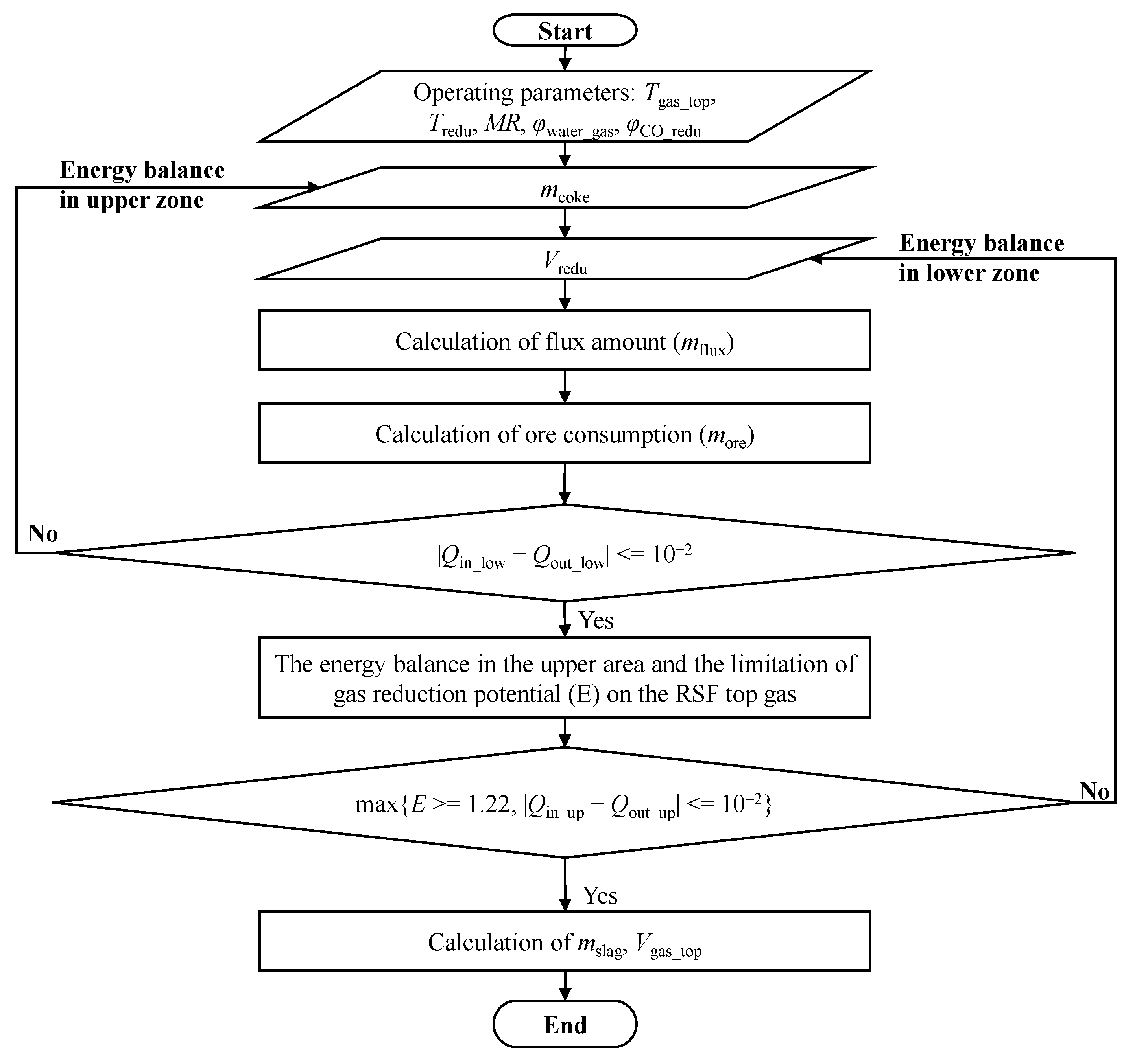
The RSF is a physical and chemical reaction process conducted in a closed and complex system, and it is impossible to obtain key process parameters inside the furnace through measurements. Therefore, constructing a mathematical model for process calculation can quantitatively obtain the changes in mass and energy inside the RSF, providing data support for subsequent parameter optimization, capacity expansion, or increasing the CO2 emission reduction limit. A reaction model of RSF was established based on the principle of mass and energy conservation, with the production per ton of hot metal (HM or molten iron) as the reference. The model obtained the mass of raw materials consumed per ton of HM, the volume and composition of reducing gas, the mass and composition of corresponding by-products such as slag, and the volume and composition of the top gas.
The process of establishing the mathematical model and its calculation process for the RSF will be described in the following section. The established mathematical model can be used to analyze and determine the volume of reducing gas and top gas required per ton of HM in the RSF, providing input and output conditions for the top gas circulation model and facilitating the selection of subsequent decarburization equipment capacity on-site.
4. Results and Discussion
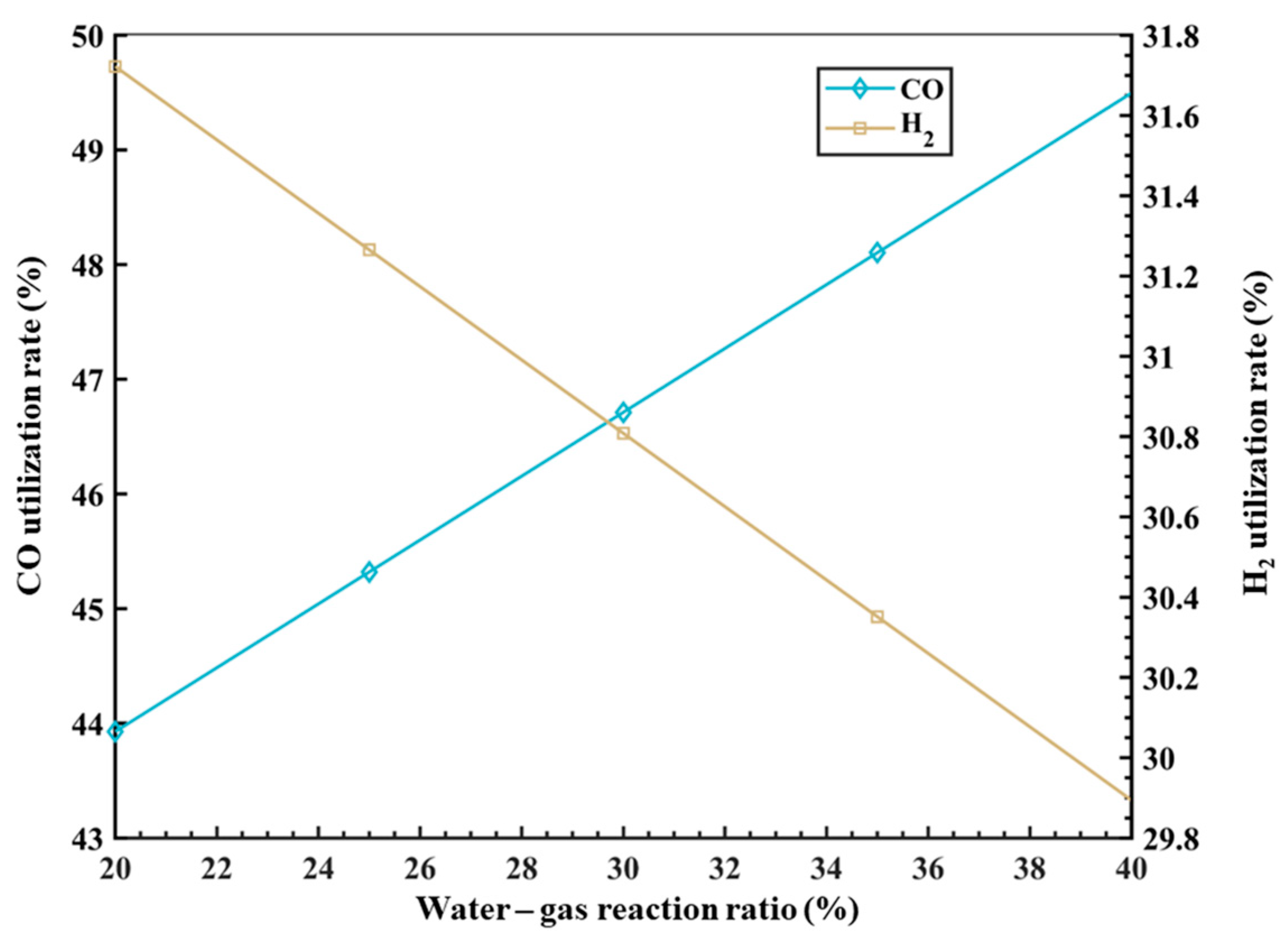
The establishment of a comprehensive mathematical model enables the understanding of quantitative relationships between various parameter variables, facilitating the adjustment of input parameters to improve the operational performance indicators of the RSF. Under specific boundary conditions, this study utilizes the developed mathematical model to analyze in-depth the effects of different variables on key smelting parameters inside the RSF. These include the temperature and composition (CO:H2) of the decarburization circulating reducing gas injected from the RSF shaft tuyere, which impact process energy consumption and carbon emissions; the variation in the metallization rate of iron ore affecting the flow rate of decarburization circulating reducing gas and the coke ratio; and the influence of the water–gas reaction ratio parameters on the utilization rates of CO and H2 in the top gas. In addition, the carbon and hydrogen footprints can be clearly drawn through the model in this paper, which provides a direction for the further optimization of the process.
4.1. Effect of Decarbonization Reducing Gas on Process Energy Consumption and Carbon Emissions
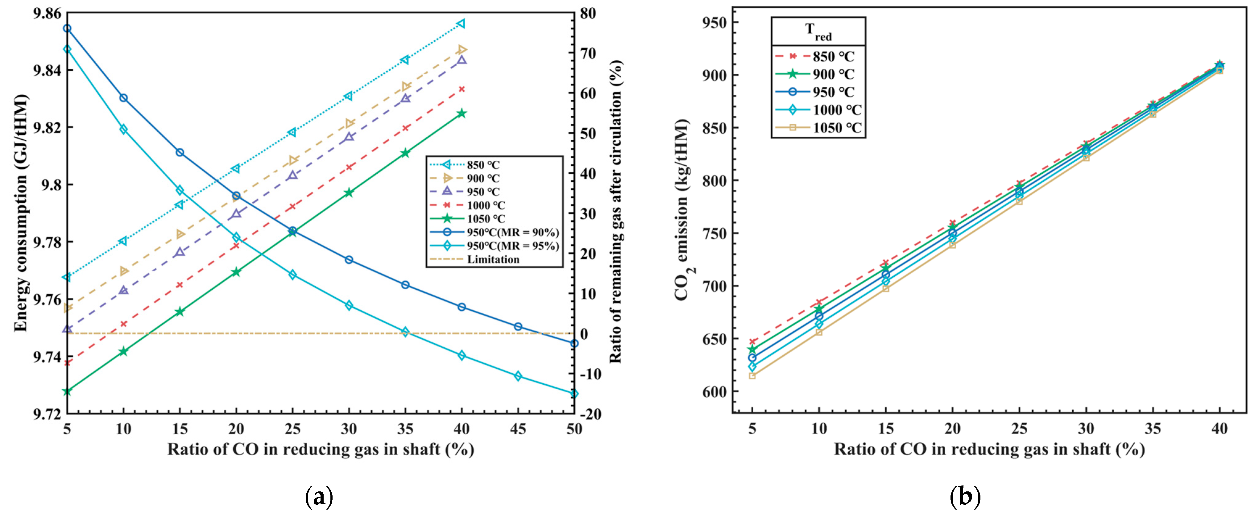
The composition and temperature of the reducing gas injected from the RSF shaft tuyere have a significant impact on the thermal balance inside the RSF and are also one of the key factors in optimizing the RSF with the Hy-O-CR process. The total energy consumption of the RSF can be obtained from the overall process heat balance model, which includes the carbon oxidation heat, high-temperature reducing gas sensible heat, hydrogen oxidation heat, methane generation heat, and slag formation heat. The model analyzes the effects of the composition (different CO ratios,
φCO_redu) and temperature (
Tredu) of the reducing gas on the total energy consumption and CO
2 emissions inside the RSF, with the calculation results shown in
Figure 3.
In
Figure 3a, it can be observed that as the CO ratio increases in the injected reducing gas (with a corresponding decrease of the H
2 ratio), the heat released from carbon oxidation gradually increases, while the heat released from hydrogen oxidation decreases. The total amount of injected reducing gas decreases, resulting in a reduction in the sensible heat brought in by the high-temperature reducing gas, but the total energy consumption increases in the whole process. The research findings indicate that increasing the CO ratio in the injected reducing gas from 5% to 40% leads to a 1% increase in energy consumption, approximately 93.8 MJ/tHM. In other words, for every 1% increase in the CO ratio, energy consumption increases by 2.68 MJ/tHM. The results above are based on hydrogen production from clean energy power generation, which does not produce any carbon emissions. Therefore, the energy consumption of hydrogen production by electrolysis is not considered in the process above, so the influence of different hydrogen production technologies on energy consumption is also one of the restrictive factors to be considered in this new process in the future. Additionally, from
Figure 3a, it can be observed that as the temperature of the injected reducing gas increases, there is a slight decrease in total energy consumption, which is due to the increase of sensible heat carried by the reducing gas and leads to the decrease of the amount of reducing gas. Under the condition of satisfying the reduction potential, it will inevitably lead to the increase of the CO utilization rate of the top gas, and then the total energy consumption will be reduced.
In addition, the comprehensive process model should also consider the proportion of residual gas after the circulation of the top gas, which is a crucial indicator for assessing the overall utilization efficiency of the new process. When the proportion of residual gas after circulation is equal to 0, it indicates that the high reduction potential gas formed after the top gas treatment is used in the cycle, which not only ensures the maximum utilization of the gas cycle, but also does not need external equipment for gas storage and supply. However, the metallization rate (
MR)is one of the main factors affecting the process above, and the model analyzes the influence of the metallization rate on the circulating gas volume, as shown in
Figure 3a. It can be seen in the figure that when the iron ore is moved down to the bottom of RSF shaft and the
MR is 90%, the
φCO_redu of the reducing gas at around 45% can meet the requirement for the complete utilization of the top gas circulation. While the
MR is 95%, the
φCO_redu of the reducing gas is approximately 35%, which can meet the requirement for the complete utilization of the top gas circulation.
At the same time, as the CO ratio of the injected reducing gas increases, the emission of CO
2 also significantly increases, as shown in
Figure 3b. The calculations of the model indicate that, while satisfying the constraints of thermal balance inside the RSF, for every 1% increase in the CO ratio of the reducing gas, the emission of CO
2 increases by approximately 7.53 kg/tHM. The temperature of the injected reducing gas has a certain influence on CO
2 emissions at low CO concentrations, but this influence diminishes as the CO concentration increases. This is because, with the increase in CO concentration, the effect of H
2 becomes weaker, resulting in a weakened reduction in CO
2 emissions.
Overall, it is currently difficult to simultaneously reduce energy costs and achieve low CO2 emissions. At present, this process has limited CO2 emissions as much as possible while considering cost control. However, with the reduction of energy costs and the development of “green hydrogen” technology in the future, there is potential for further optimization and adjustment of the process parameters to break through the upper limit of emission reduction and achieve even greater emission reductions.
4.4. Analysis of Carbon–Hydrogen Footprints
The reduced melting furnace process described in this article adopts a carbon–hydrogen dual reducing agent coupling method to reduce iron oxides in the furnace. Due to its excellent performance in the BF, coke or carbon-based gases are still extensively used in this model. Through mathematical modeling of different zones, a quantitative analysis can be conducted on the forms and footprints of carbon-containing substances at various inlet and outlet points in the RSF. The carbon footprint flow can provide a better analysis of the usage status of carbon-based materials and CO2 emissions, enabling a more accurate assessment of the new process in terms of carbon reduction requirements and national policies, in order to establish suitable operational systems. Additionally, a high proportion of hydrogen in the reducing gas of the RSF is the main driving force in the reduction process. By establishing the hydrogen footprint flow, the utilization status of hydrogen-based materials in the RSH can be clarified. In a relatively short period, due to the current technological limitations, there is a higher cost for hydrogen production. However, it is possible to lower the overall process cost by appropriately increasing the hydrogen recycling ratio and enhancing water reuse.
Figure 6 shows the carbon and hydrogen footprints in two different scenarios. The main sources of carbon in the new process flow are coke and carbon-containing reducing gas (CO and CO
2) injected into the RSF shaft tuyere. The main expenditures include the form of [Fe
3C] entering the carbon-containing hot metal and carbon-containing gases (CO and CO
2) discharged from the top of the furnace in gas form. After being processed by different top gas purification devices, a portion of the carbon-containing gas of the top gas is burned and directly released into the atmosphere in the form of CO
2, while the remaining gas is captured by the CO
2 separator and used as a kind of gas source for oil displacement underground. The rest of the gas is recycled in the form of CO.
There are two main sources of hydrogen in the new process flow. In addition to the moisture in the raw materials and volatiles from coke, the vast majority comes from green hydrogen produced by the electrolysis of water. After passing through the RSF, the product is water, a portion of which is released into the atmosphere after combustion for heat generation, while the rest is removed from the dryer and stored for recycling.
In
Figure 6a,b of scenario 1, the boundary conditions were the temperature of the reducing gas (
Tredu = 950 °C), the CO ratio (
φCO_redu = 30%) of the reducing gas, the temperature of the top gas (
Ttop_gas = 200 °C), the water–gas reaction ratio in the RSF (
φwater_gas = 20%), and the metallization rate (
MR = 90%) of iron ore in the bottom of the RSF shaft. In
Figure 6c,d of scenario 2, the boundary conditions were
Tredu = 950 °C,
φCO_redu = 20%
Ttop_gas = 200 °C,
φwater_gas = 30%, and
MR = 95%. The data presented in the figure refer to the mass of C or H elements expressed in different ways of CO
2, CO, C, H
2O, and H
2, kg/tHM.
Through a comparative analysis of the two cases, it can be observed that with the variation of the operating parameters, the carbon content in the circulating gas, CO, decreased from 170.76 kg/tHM to 113.79 kg/tHM, and the carbon content in CO2 also decreased accordingly, from 22.76 kg/tHM to 21.47 kg/tHM. The mass of hydrogen in circulation increased from 32.99 kg/tHM to 35.35 kg/tHM, but the amount of hydrogen supplemented through the electrolysis of water also increased from 33.39 kg/tHM to 40.47 kg/tHM.
The emission of CO2 is a crucial parameter for measuring and evaluating the new process model. Compared to traditional BF processes, this new process results in lower direct CO2 emissions. Based on an analysis of the two cases, the direct CO2 emissions decreased from 58.89 Nm3/tHM (equivalent to CO2 emissions of 215.93 kg/tHM) to 48.85 Nm3/tHM (equivalent to CO2 emissions of 179.12 kg/tHM). In comparison to the CO2 emissions from traditional BFs (1400 kg/tHM), the proportion of direct emission reduction increased from 84.58% to 87.21%. These analyses are based on the CCUS (carbon capture, utilization, and storage) technology in the new process. Alternatively, without CCUS technology, the CO2 emissions would decrease from 729.85 kg/tHM to 660.73 kg/tHM, resulting in an increase in emission reduction proportion from 47.87% to 52.81%. This target value significantly surpasses existing technologies, such as the BF with hydrogen-rich or oxygen-enriched processes, providing a new direction for the technological development of hydrogen metallurgy. It also offers data support for subsequent parameter optimization of this new model.


