Article

On the Competition between Pores and Hidden Entrainment Damage during In Situ Tensile Testing of Cast Aluminum Alloy Components

by
Jakob Olofsson
1,
Toni Bogdanoff
1 and
Murat Tiryakioğlu
2,*
1
Department of Materials and Manufacturing, School of Engineering, Jönköping University, P.O. Box 1026, SE-551 11 Jönköping, Sweden
2
School of Engineering and Technology, Jacksonville University, Jacksonville, FL 32211, USA
*
Author to whom correspondence should be addressed.
Metals 2024, 14(10), 1175; https://doi.org/10.3390/met14101175
Submission received: 3 August 2024 / Revised: 5 October 2024 / Accepted: 9 October 2024 / Published: 16 October 2024
(This article belongs to the Special Issue Advances in Lightweight Alloys)

Abstract

:
The competition between pores and hidden entrainment defects during tensile testing of specimens from Al-Si-Cu alloy high-pressure die castings has been characterized. In all tests, multiple strain concentrations have been identified by using the digital image correlation technique and the final fracture has been preceded by a competition between pores and hidden damage, later identified as oxide bifilms. The results have confirmed previous findings that overall damage to the metal during its liquid state is much more extensive than what can be assessed via X-ray inspection, which looks only for pores. It is concluded that current quality assurance techniques need to be updated.

1. Introduction

Pores have been the main target of most of the quality assurance practices in the casting industry. Final accept/reject decisions have been made based on the size and location of pores in the X-ray inspection of castings [1]. This has led the industry to adopt practices that minimize the size of pores or even eliminate them. Eliminating pores is expected to increase the performance of castings because, from a mechanical engineering point of view, pores (or voids) create stress concentrations around them that can lead to the initiation of a fatigue crack. This is also supported by the findings that pores are more detrimental as fatigue crack initiators than oxide inclusions [2]. In general, pores are so common in castings that some researchers [3,4] assume that they are intrinsic in castings, i.e., no matter what is done, there will always be pores at the end of solidification. However, theoretical calculations have shown that liquid metals are quite resistant to pore nucleation. Campbell [5] has shown that the fracture pressure that needs to be reached in aluminum to nucleate a pore is in the order of 3 GPa. Yousefian and Tiryakioğlu [6] have found that same fracture pressure and showed that it is impossible to nucleate a pore through the commonly assumed mechanism of vacancy clusters. Finally, Tiryakioğlu [7] has determined that hydrogen dissolved in liquid aluminum cannot overcome the nucleation barrier in liquid aluminum. Hence, for pore formation, either air needs to be entrained, leading to bubbles in the liquid metal, or the nucleation step in pore formation needs to be circumvented completely. For the latter, the only mechanism available is the opening of folded-over oxide films, i.e., bifilms [8].
Due to the high affinity of aluminum for oxygen, aluminum reacts with oxygen within nanoseconds [9] to form a continuous film of first amorphous alumina [10,11], which then transforms to γ-Al2O3 after a critical thickness has been reached [12,13]. Eventually, γ-Al2O3 transforms to α-Al2O3, alternatively referred to as corundum. These oxide films remain harmless as long as they remain on the surface. However, the current casting technology not only disrupts this surface but also involves the creation of new surface, especially during pouring and mold filling [14,15]. Consequently, these films fold over during liquid processing and mold filling to form two layers of oxides that have perfect bonding on one side and zero bonding between them, forming the Griffiths crack as suggested by Campbell [16]. These entrainment defects are already present in the body of the ingots [17,18] and damage to the liquid metal increases at every step of aluminum casting production [19]. Such liquid damage impairs structural integrity [20,21], causing a reduction in the work hardening rate and resulting in premature failure [21]. Due to lack of bonding between the two layers of bifilms, they act as a crack and open without any resistance under tensile stress, leading to premature fracture. Hence, mechanical properties, especially ductility [21,22,23,24] and fatigue performance [2,25,26], are strongly reduced by the presence of bifilms. For a review of techniques to minimize these entrainment defects, the reader is referred to the works of Campbell [27,28,29].
The authors [30] have recently characterized how hidden damage, i.e., bifilms, compete with each other to cause the final fracture in aluminum high-pressure die castings (HDPCs) in which no pores could be found in X-ray inspections following the usual industrial quality assurance checks. To do this, the digital image correlation (DIC) technique has been used to characterize the strain concentrations in situ during tensile testing. They have shown that tensile behavior in all specimens could be categorized as a competition to final fracture: as (i) a single strain concentration winning the competition early and leading to final fracture or as (ii) multiple strain concentrations competing until final fracture. In all cases, the strain concentrations, whether the “winner” or “runner-up” in the competition, have been determined to be bifilms. Hence, hidden damage that could not be caught with X-ray inspection could still be quite detrimental to the performance of castings, even though these castings would pass all quality assurance practices that focus only on pores.
Recently, it has been shown [31] that pores, i.e., visible damage, are more detrimental to the performance of cast aluminum alloys than any coarse microstructure because they lead to earlier crack initiation during tensile and fatigue testing. The present study is intended to build on the results obtained in HPDC specimens with no pores [30] and characterize the competition between the pores and hidden damage in aluminum alloy HPDCs. To the authors’ knowledge, such a study has not been conducted before.

2. Materials and Methods

The chemical composition of the EN AC 46,000 alloy used in this study, as measured with optical spectroscopy, is shown in Table 1. Specimens were cast at a commercial foundry in a standard HPDC die-casting machine under nonoptimal conditions to intentionally produce pores in the castings. The mold had a cavity with the specimen geometry of 200 mm in length, 6 mm in thickness, 35 mm in width, and two 75 mm radii to create a minimum width of 20 mm in the specimen center. More than 300 samples were produced to ensure conditions similar to serial production, such as steady-state mold temperature. Industrial X-ray equipment with a resolution of 0.1 mm was used to inspect all samples. The specimens were machined on both sides to a thickness of 3 mm to ensure parallel surfaces and reduce the effect of cast surface-related defects, as well as to obtain plane stress conditions. No further treatment was performed on the specimens after machining. Additionally, the specimens were inspected visually after machining to ensure that no cracks or pores could be identified on the surface of the specimens. Specimens were tested at room temperature in a tensile testing machine at a constant crosshead speed of 0.35 mm/min. The digital image correlation (DIC) technique was employed to determine the strain concentrations during tensile testing. A total of eight specimens with pores were tested. Further details of the experimental setup are provided in Ref. [30].
A finite element method (FEM) simulation was conducted for the tensile specimen geometry to determine the expected strain pattern during tensile testing if no defects were leading to strain concentrations. The FEM simulation was performed in Abaqus™ using second-order hexagonal elements with reduced integration (C3D20R). The element size was about 1 mm, resulting in a total of 152,367 elements in the mesh of the 3D geometry. The assigned elasto-plastic material behavior was derived from pure uniaxial testing of the same material, as described in a previous work [32].

3. Results and Discussion

The FEM results are presented in Figure 1, which shows a generic strain distribution in this geometry subjected to tensile load. The figure clearly shows that in the absence of any structural defects, the highest strain would be expected near the two outer surfaces of the smallest cross-sectional area where the geometrical stress concentration is the highest.
The deformation and fracture behavior of the eight specimens has been analyzed. The results have indicated that the deformation and fracture behavior of all specimens can be categorized in three types of competition, (i) with an early winner, (ii) with a late leader, and (iii) to the end.

3.1. Competition with an Early Leader

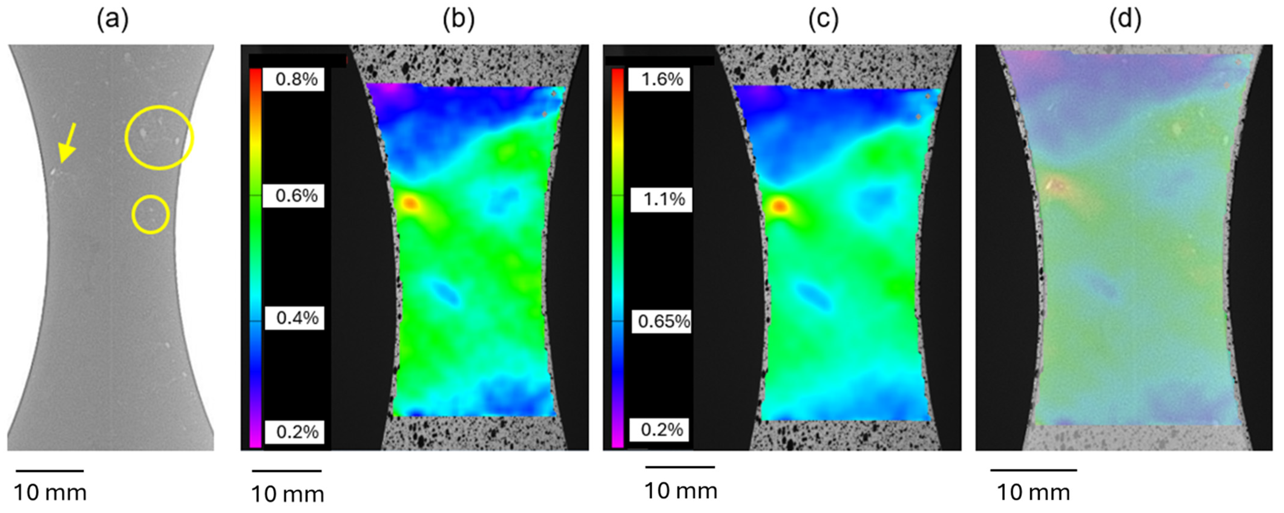
An X-ray image of the first specimen is presented in Figure 2a, which shows the location of the pores. Several clusters of pores are apparent and are indicated by circles in Figure 2a. Two of these clusters are indicated with circles in Figure 2a. There is another pore close to the surface, as indicated by an arrow. These three locations are expected to compete for the final fracture of the specimen. These pores should be due to air entrainment during the HPDC process. Entrained air leaves a trail of oxides behind [33] that can be considered a continuous path of bifilms. Any dissolved hydrogen in the melt is not expected to contribute to pore formation because the solubility of hydrogen is higher at the solidus temperature than at the liquidus temperature in aluminum HPDC alloys [34].
Strain distributions at loads of 10.0 and 12.8 kN are presented in Figure 2b and Figure 2c, respectively. Note that strain distribution is very different from the one presented in Figure 1 and is not symmetrical near the smallest cross-sectional area and in the area indicated by the arrow in Figure 2a. It is also clear that the highest strain concentration is in the vicinity of the pore closest to the surface. Figure 2d shows the X-ray image superimposed on the strain distribution in Figure 2c. It is clear that the pore cluster near the top of the specimen is the cause of the strain concentration. It is also evident that the highest strain concentration is to the right of the pore near the surface, going toward the center of the specimen. This is unusual because the strain concentration would be expected to be either symmetrical around the pore, as taught in materials and mechanical engineering textbooks, or be higher toward the surface of the specimen, away from the center. This strain concentration has led to the final fracture of the specimen. This is a case of one strain concentration leading the race to final fracture from early on and winning the competition in the end, similar to the cases seen in pore-free HDPCs previously [14].
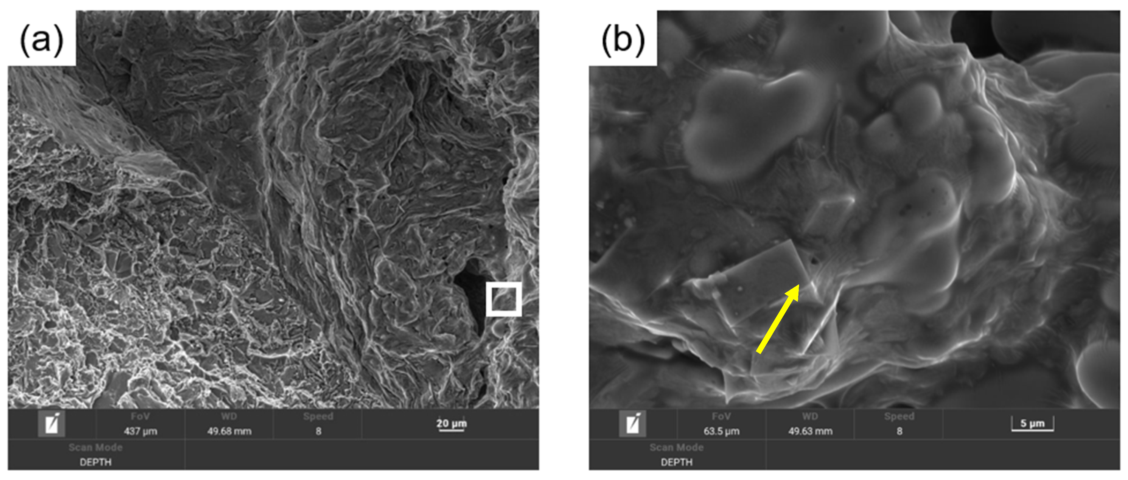
The fracture surface of this specimen has been investigated in a scanning electron microscope (SEM). The pore with the strain concentration next to it is presented in Figure 3a. The interior surface of the pore was found to be covered by an oxide film, which indicates that it is indeed a bubble entrained during mold filling. Note that there is a crevice at the bottom of the pore. The details of this feature are shown in Figure 3b. The two sides of the oxide film merge together at this feature and form a bifilm. This feature has been interpreted as the trail of the bubble that has collapsed under the pressure applied during solidification. Evidently, the pressure during solidification was high enough to collapse the bubble trail but not the bubble itself.
The details of the region where the strain concentration was observed are shown in Figure 4a. This area has a large area of oxide films on the entire surface, as indicated by the rectangle, which is presented in Figure 4b. As can be seen, there is a very thin, transparent oxide film, usually referred to as a “young” oxide film [35]. The wrinkle in the film is indicated by the arrow in Figure 4b. This oxide film has been interpreted to have formed during mold filling and drapes over the dendrite tips and intermetallic particles, which have been shown to precipitate heterogeneously on bifilms [36,37,38,39,40]. Similar oxide films around bubbles have been reported previously [41,42,43,44], with thicknesses ranging between 0.1 and 0.2 μm.
Another feature that was observed on the fracture surface toward the middle of the specimen is presented in Figure 5. Note that the two sides of this feature seem to be unbonded, especially on the right-hand side, and it goes into the specimen. This is interpreted as a bifilm, similar to the bifilms shown by Fox and Campbell [45]. The bifilm has formed as a bubble trail during the highly turbulent filling of the specimen [33], similar to the one in Figure 3b.

3.2. Competition with a Late Leader

An example of the competition of multiple strain concentrations is presented in Figure 6. Note that there are many small pores in the X-ray of the specimen (Figure 6a). At a load of 10.4 kN, several strain concentrations are visible near the center of the specimen (Figure 6b). With increasing load, one strain concentration becomes more prominent (Figure 6c). At a load of 14.0 kN, immediately before the fracture, one strain concentration is clearly the leader, although others near the smallest cross-sectional area are still visible (Figure 6d). The final fracture path, presented in Figure 6e, goes through the leading strain concentration.
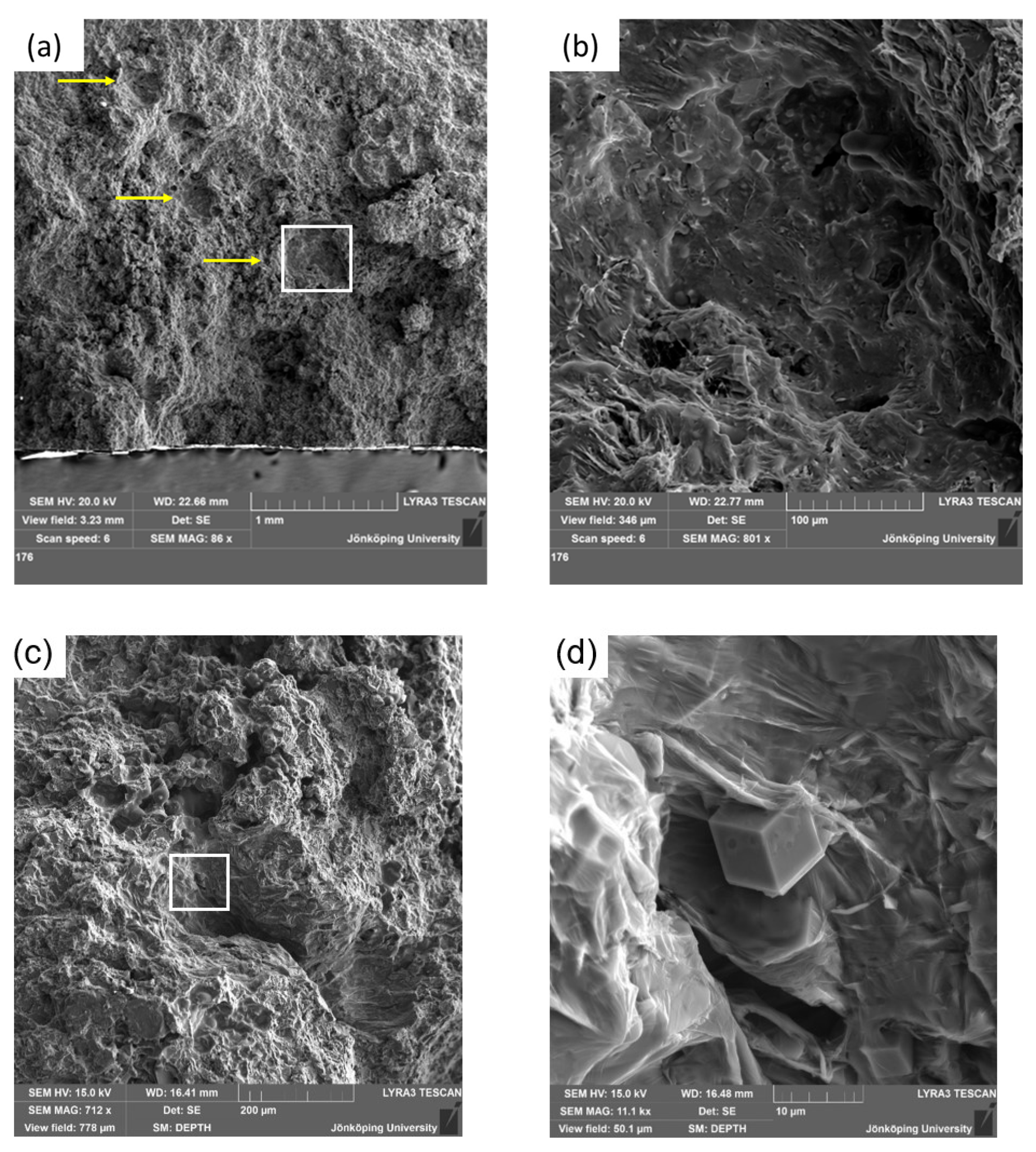
The analysis of the fracture surface of this specimen at the location of the leading strain concentration is presented in Figure 7. Note that there are several oxides, as highlighted with yellow arrows in Figure 7a. The details of the square shown in Figure 7a are presented in Figure 7b, which indicates the presence of an oxide film draped over the microstructure. Another area in the strain concentration is shown in Figure 7c, with a white square. The details of this square are given in Figure 7d, which shows an oxide film draping over cubic intermetallics which have precipitated on it [38]. These results indicate that these bifilms formed in the liquid state are the reason for the leading strain concentration. Hence, the competition in this specimen with small pores visible in the X-ray has been won by the hidden entrainment damage.
Several other intermetallics have been found in the same region, as presented in Figure 8. Similar to Figure 7b, the entire surface in Figure 8 is covered by a thin oxide film. Wrinkles in the film, as well as a crack, are indicated in Figure 8. Energy-dispersive X-ray spectroscopy (EDS) analysis of these intermetallics has shown large concentrations of Fe, Mn, Si and some Cr. Consequently, they are identified as polyhedral sludge particles [46,47,48]. Ferraro et al. [46] described these particles as Alx(Fe, Mn, Cr)ySiz with variable composition and their structure as a regular rhombic dodecahedron.

3.3. Competition to the End

An example of the competition between multiple strain concentrations up to the final fracture is presented in Figure 9. There are two visible, large holes in the X-ray image of the specimen, presented in Figure 9a. The larger one is closer to the surface and lies in a smaller cross-sectional area. Therefore, the main strain concentration is expected to develop at that location. At a load of 9.0 kN, several strain concentrations are developing near the smallest cross-sectional area and below, as well as one near the two pores, as can be seen in Figure 9b. At a load of 12.4 kN, one strain concentration on the left, just below the smallest cross-sectional area, as well as another one further south, near the midplane of the specimen, become more prominent (Figure 9c). The X-ray image in Figure 9a superimposed on the strain field in Figure 9c is presented in Figure 9d. Note that the largest pore near the surface does not correspond to any leading strain concentrations. There are, however, two strain bands developing on either side of the large pore. Nevertheless, the final fracture, presented in Figure 9e, does go through the largest pore.
The SEM analysis of the fracture surface is presented in Figure 10. Note that the pore is near the rear surface of the specimen, which has most likely hidden the strain concentration developed during testing. An oxide film covers the interior surface of the pore. Hence, this pore is also a bubble, created through air entrainment during mold filling, having reacted and possibly consumed all oxygen in the bubble [49].
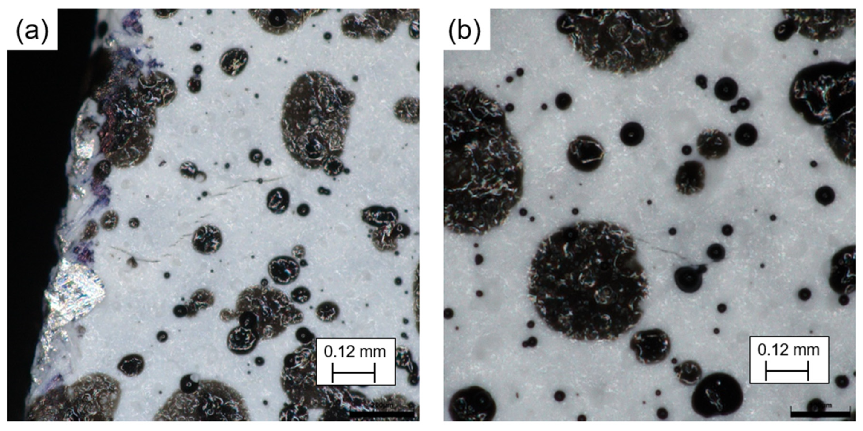
The surface of the specimen has been inspected in the area of the two prominent strain concentrations in Figure 9c. In both locations, cracks have been identified on the surface, as presented in Figure 11. The strain concentration nearest to the minimum cross-sectional area, as shown in Figure 11a, is due to multiple cracks on the surface of the specimen. The more prominent strain concentration near the center of the specimen was created by the formation of a single crack, as presented in Figure 11b. These cracks have been attributed to hidden damage in specimens with no pores through the characterization of the cracks with an optical microscope, as confirmed in the earlier study by the authors [30]. Consequently, these cracks are also attributed to hidden bifilms that have opened due to tensile stresses. Similar results have also been reported [50] for an Al-Si-Cu-Mg (A319) alloy casting.
The results presented in this study clearly demonstrate that pores are always associated with bifilms, which is in agreement with prior observations [51,52] as well as theoretical calculations [3,4,5]. A recent study by Song et al. [53] showed that bifilms around pores open up during tensile deformation of high-pressure die-cast magnesium alloy castings. The results of the present study are in complete agreement with those of Song et al. Hence, the cracks shown in situ [50,54,55] that open early during the tensile deformation of cast aluminum alloys are indeed due to the hidden damage to the metal in the liquid state. This is also in agreement with recent results reported from in situ fatigue testing in which short secondary cracks were observed away from the stress concentrations in cast aluminum alloys without any pores [56,57]. The analysis of these cracks showed that they are indeed bifilms which open upon the application of a tensile stress.
In the presence of pores, the bifilms around them have a higher chance of leading and winning the competition between strain concentrations because pores are known to create higher stresses around them. However, even if the pores are closed, the hidden damage to the liquid metal will continue to degrade the mechanical properties and in-service performance of these castings. Therefore, battling pores in castings should only be the first step in the quality improvement efforts in castings, and definitely not the last step. Moreover, there should be an industry-wide recognition that the current quality assurance standards and techniques are no longer sufficient to meet the higher performance and safety demands that are now put on castings. These standards must be updated immediately. Since bifilms cannot withstand tensile stresses due to the lack of bonding between the two layers, a possible first step can be to require integrally attached test coupons that should be tested under tension so that acceptance decisions for casting quality are made based on tensile results.

4. Conclusions

The results of this study have shown the following:
  • There is always competition between multiple strain concentrations during tensile testing of HPDC Al-alloys. Visible (pores) and hidden (invisible bifilms) damage competes in the early stages of tensile deformation. This competition for the final fracture can have an early winner or it can continue till the end.
  • Strain concentration around a pore does not necessarily have the uniformity taught in mechanical engineering textbooks. This is due to bifilms that remain hidden near pores and that open during tensile deformation.
  • Pores provide stress concentration around them, causing bifilms in their vicinity to open earlier than in areas without pores.
  • Hidden bifilms can win the competition even when there are pores in the casting.
  • Battling pores is the first step of quality improvement efforts, but definitely not the last.
  • Current quality assurance systems that assess the quality of casting based solely on pores are outdated and should be updated immediately.

Author Contributions

Conceptualization, J.O. and T.B.; methodology, J.O., T.B. and M.T.; software, J.O.; validation, T.B. and M.T.; formal analysis, J.O., T.B. and M.T.; investigation, J.O. and T.B.; resources, J.O.; data curation, J.O. and T.B.; writing—original draft preparation, M.T. and J.O.; writing—review and editing, M.T., J.O. and T.B.; visualization, J.O. and T.B.; supervision, M.T.; project administration, J.O.; funding acquisition, J.O. All authors have read and agreed to the published version of the manuscript.

Funding

The authors thank the Swedish funding agency VINNOVA for the financial support of the project EVIDENT, 2022-02552.

Data Availability Statement

The original contributions presented in the study are included in the article, further inquiries can be directed to the corresponding author.

Acknowledgments

The authors gratefully acknowledge Johan Börjesson for support with the FIB-SEM analyses and Jacob Steggo for support with the DIC measurements.

Conflicts of Interest

The authors declare no conflicts of interest.

References

  1. Mil-a-21180 d. In Aluminum-Alloy Castings; Department of Defense: Washington, DC, USA, 1984.
  2. Wang, Q.; Crepeau, P.; Davidson, C.; Griffiths, J. Oxide films, pores and the fatigue lives of cast aluminum alloys. Metall. Mater. Trans. B 2006, 37, 887–895. [Google Scholar] [CrossRef]
  3. Katgerman, L.; Eskin, D.G. In search of prediction of hot cracking in aluminium alloys. In Hot Cracking Phenomena in Welds II; Böllinghaus, T., Herold, H., Cross, C.E., Lippold, J.C., Eds.; Springer: Berlin, Germany, 2008; pp. 3–18. [Google Scholar]
  4. Nazarboland, A.; Elliott, R. The effect of intrinsic casting defects on the mechanical properties of austempered, alloyed ductile iron. Int. J. Cast Met. Res. 1997, 10, 87–97. [Google Scholar] [CrossRef]
  5. Campbell, J. Pore nucleation in solidifying metals. In Proceedings of the Conference on the Solidification of Metals, Brighton, UK, 4–7 December 1967; Institute of Metals Publication: London, UK, 1968; pp. 18–26. [Google Scholar]
  6. Yousefian, P.; Tiryakioğlu, M. Pore formation during solidification of aluminum: Reconciliation of experimental observations, modeling assumptions, and classical nucleation theory. Metall. Mater. Trans. A 2018, 49, 563–575. [Google Scholar] [CrossRef]
  7. Tiryakioğlu, M. On the heterogeneous nucleation pressure for hydrogen pores in liquid aluminium. Int. J. Cast Met. Res. 2020, 33, 153–156. [Google Scholar] [CrossRef]
  8. Campbell, J. Entrainment defects. Mater. Sci. Technol. 2006, 22, 127–145. [Google Scholar] [CrossRef]
  9. Yousefi, E.; Sun, Y.; Kunwar, A.; Guo, M.; Moelans, N.; Seveno, D. Surface tension of aluminum-oxygen system: A molecular dynamics study. Acta Mater. 2021, 221, 117430. [Google Scholar] [CrossRef]
  10. Stucki, F.; Erbudak, M.; Kostorz, G. The initial oxidation of solid and liquid aluminium. Appl. Surf. Sci. 1987, 27, 393–400. [Google Scholar] [CrossRef]
  11. Bedair, S.; Smith, H.P., Jr. Leed studies of oxygen adsorption on the (111) and (110) surfaces of aluminum. J. Appl. Phys. 1971, 42, 3616–3618. [Google Scholar] [CrossRef]
  12. Reichel, F.; Jeurgens, L.; Richter, G.; Mittemeijer, E. Amorphous versus crystalline state for ultrathin Al2O3 overgrowths on al substrates. J. Appl. Phys. 2008, 103, 093515. [Google Scholar] [CrossRef]
  13. Men, H.; Fan, Z. Transition of amorphous to crystalline oxide film in initial oxide overgrowth on liquid metals. Mater. Sci. Technol. 2011, 27, 1033–1039. [Google Scholar] [CrossRef]
  14. Cox, M.; Harding, R.A.; Campbell, J. Optimised running system design for bottom filled aluminium alloy 2l99 investment castings. Mater. Sci. Technol. 2003, 19, 613–625. [Google Scholar] [CrossRef]
  15. Lai, N.; Griffiths, W.; Campbell, J. Modelling of the potential for oxide film entrainment in light metal alloy castings. In Proceedings of the Tenth International Conference on Modeling of Casting, Welding and Advanced Solidification Processes, Destin, FL, USA, 25–30 May 2003; pp. 415–422. [Google Scholar]
  16. Campbell, J. The origin of Griffith cracks. Metall. Mater. Trans. B 2011, 42, 1091–1097. [Google Scholar] [CrossRef]
  17. Erzi, E.; Tiryakioğlu, M. A simple procedure to determine incoming quality of aluminum alloy ingots and its application to a356 alloy ingots. Int. J. Met. 2020, 14, 999–1004. [Google Scholar] [CrossRef]
  18. Gyarmati, G.; Kéri, Z.; Mende, T.; Molnár, D. Analysis of the quality of incoming alsi9mn alloy ingots. Int. J. Met. 2024, 18, 1723–1738. [Google Scholar] [CrossRef]
  19. Bogdanoff, T.; Tiryakioglu, M.; Jarfors, A.E.W.; Ghassemali, E. A simple procedure to assess the complete melt quality in aluminium castings: Implementation in a die-casting and a rheo-casting. Int. J. Cast Met. Res. 2023, 37, 71–79. [Google Scholar] [CrossRef]
  20. Dai, X.; Yang, X.; Campbell, J.; Wood, J. Effects of runner system design on the mechanical strength of al–7si–mg alloy castings. Mater. Sci. Eng. A 2003, 354, 315–325. [Google Scholar] [CrossRef]
  21. Tiryakioǧlu, M.; Campbell, J.; Staley, J.T. The influence of structural integrity on the tensile deformation of cast al–7wt.%si–0.6 wt.%mg alloys. Scr. Mater. 2003, 49, 873–878. [Google Scholar] [CrossRef]
  22. Tiryakioğlu, M.; Staley, J.T.; Campbell, J. The effect of structural integrity on the tensile deformation characteristics of a206-t71 alloy castings. Mater. Sci. Eng. A 2008, 487, 383–387. [Google Scholar] [CrossRef]
  23. Tiryakioğlu, M.; Campbell, J.; Alexopoulos, N.D. On the ductility of cast al-7 pct si-mg alloys. Metall. Mater. Trans. A 2009, 40, 1000–1007. [Google Scholar] [CrossRef]
  24. Hu, M.-L.; Guo, H.-M.; Yang, K.-Y.; Chang, W.-J.; Deng, B.; Luo, J.-T. Bifilm defects in alsi10mgmn alloy castings. Int. J. Met. 2023, 18, 2944–2957. [Google Scholar] [CrossRef]
  25. Campbell, J.; Tiryakioğlu, M. Fatigue failure in engineered components and how it can be eliminated: Case studies on the influence of bifilms. Metals 2022, 12, 1320. [Google Scholar] [CrossRef]
  26. Staley, J.T., Jr.; Tiryakioğlu, M.; Campbell, J. The effect of hot isostatic pressing (hip) on the fatigue life of a206-t71 aluminum castings. Mater. Sci. Eng. A 2007, 465, 136–145. [Google Scholar] [CrossRef]
  27. Campbell, J. The Mechanisms of Metallurgical Failure: On the Origin of Fracture; Butterworth-Heinemann: Oxford, UK, 2020. [Google Scholar]
  28. Campbell, J. Complete Casting Handbook: Metal Casting Processes, Metallurgy, Techniques and Design; Elsevier Butterworth-Heinemann: Oxford, UK, 2011. [Google Scholar]
  29. Campbell, J. Mini Casting Handbook; Aspect Design: Malvern, UK, 2018. [Google Scholar]
  30. Olofsson, J.; Bogdanoff, T.; Tiryakioğlu, M. On revealing hidden entrainment damage during in situ tensile testing of cast aluminum alloy components. Mater. Charact. 2024, 208, 113647. [Google Scholar] [CrossRef]
  31. Yang, B.-C.; Chen, S.-F.; Song, H.-W.; Zhang, S.-H.; Chang, H.-P.; Xu, S.-W.; Zhu, Z.-H.; Li, C.-H. Effects of microstructure coarsening and casting pores on the tensile and fatigue properties of cast a356-t6 aluminum alloy: A comparative investigation. Mater. Sci. Eng. A 2022, 857, 144106. [Google Scholar] [CrossRef]
  32. Olofsson, J. Integrated Fatigue Life Predictions of Aluminium Castings Using Simulated Local Microstructure and Defects. In Proceedings of the IOP Conference Series: Materials Science and Engineering, Banff, AB, Canada, 18–23 June 2023; IOP Publishing: Bristol, UK, 2023; p. 012067. [Google Scholar]
  33. Divandari, M.; Campbell, J. Mechanisms of bubble trail formation in castings. Trans. AFS 2001, 109, 433–442. [Google Scholar]
  34. Tiryakioğlu, M. On estimating the hydrogen solubility in solid aluminium alloys and the hydrogen solubility difference between the liquidus and solidus temperatures. Int. J. Cast Met. Res. 2021, 34, 83–87. [Google Scholar] [CrossRef]
  35. Nyahumwa, C.; Green, N.R.; Campbell, J. Influence of casting technique and hot isostatic pressing on the fatigue of an al-7si-mg alloy. Metall. Mater. Trans. A 2001, 32, 349–358. [Google Scholar] [CrossRef]
  36. Miresmaeili, S.M.; Campbell, J.; Shabestari, S.G.; Boutorabi, S.M.A. Precipitation of sr-rich intermetallic particles and their influence on pore formation in sr-modified a356 alloy. Metall. Mater. Trans. A 2005, 36, 2341–2349. [Google Scholar] [CrossRef]
  37. Cao, X.; Campbell, J. Morphology of β-al5fesi phase in al-si cast alloys. Mater. Trans. 2006, 47, 1303–1312. [Google Scholar] [CrossRef]
  38. Cao, X.; Campbell, J. The solidification characteristics of fe-rich intermetallics in al-11.5si-0.4mg cast alloys. Metall. Mater. Trans. A 2004, 35, 1425–1435. [Google Scholar] [CrossRef]
  39. Cao, X.; Campbell, J. Effect of sr on primaryα-fe phase in liquid al-11.5si-0.4mg cast alloy. Mater. Sci. Technol. 2004, 20, 514–520. [Google Scholar] [CrossRef]
  40. Cao, X.; Saunders, N.; Campbell, J. Effect of iron and manganese contents on convection-free precipitation and sedimentation of primary α-al(femn)si phase in liquid al-11.5si-0.4mg alloy. J. Mater. Sci. 2004, 39, 2303–2314. [Google Scholar] [CrossRef]
  41. Nayebi, B.; Divandari, M. Characteristics of dynamically formed oxide films on molten aluminium. Int. J. Cast Met. Res. 2012, 25, 270–276. [Google Scholar] [CrossRef]
  42. Divandari, M.; Campbell, J. Oxide film characteristics of al–7si–mg alloy in dynamic conditions in casting. Int. J. Cast Met. Res. 2004, 17, 182–187. [Google Scholar] [CrossRef]
  43. Azarmehr, S.; Divandari, M.; Arabi, H. Investigation on thickness of short time oxide films in al–1mg and al–2mg alloys. Mater. Sci. Technol. 2012, 28, 1295–1300. [Google Scholar] [CrossRef]
  44. Mirak, A.R.; Divandari, M.; Boutorabi, S.M.A.; Campbell, J. Oxide film characteristics of az91 magnesium alloy in casting conditions. Int. J. Cast Met. Res. 2007, 20, 215–220. [Google Scholar] [CrossRef]
  45. Fox, S.; Campbell, J. Visualisation of oxide film defects during solidification of aluminium alloys. Scr. Mater. 2000, 43, 881–886. [Google Scholar] [CrossRef]
  46. Ferraro, S.; Fabrizi, A.; Timelli, G. Evolution of sludge particles in secondary die-cast aluminum alloys as function of fe, mn and cr contents. Mater. Chem. Phys. 2015, 153, 168–179. [Google Scholar] [CrossRef]
  47. Ferraro, S.; Bjurenstedt, A.; Seifeddine, S. On the formation of sludge intermetallic particles in secondary aluminum alloys. Metall. Mater. Trans. A 2015, 46, 3713–3722. [Google Scholar] [CrossRef]
  48. Ceschini, L.; Morri, A.; Toschi, S.; Bjurenstedt, A.; Seifeddine, S. Influence of sludge particles on the fatigue behavior of al-si-cu secondary aluminium casting alloys. Metals 2018, 8, 268. [Google Scholar] [CrossRef]
  49. Griffiths, W.D.; Raiszadeh, R. Hydrogen, porosity and oxide film defects in liquid al. J. Mater. Sci. 2009, 44, 3402–3407. [Google Scholar] [CrossRef]
  50. Hwang, J.Y.; Doty, H.W.; Kaufman, M.J. The effects of mn additions on the microstructure and mechanical properties of al–si–cu casting alloys. Mater. Sci. Eng. A 2008, 488, 496–504. [Google Scholar] [CrossRef]
  51. Tiryakioğlu, M.; Yousefian, P.; Eason, P.D. Quantification of entrainment damage in a356 aluminum alloy castings. Metall. Mater. Trans. A 2018, 49, 5815–5822. [Google Scholar] [CrossRef]
  52. Zhang, Q.; Liljenfors, T.; Jonsson, S.; Jarfors, A.E.W. On the application of reduced pressure test for the prediction of ductility of 46000 alloy: Role of pore’s morphology and distribution. J. Mater. Res. Technol. 2024, 31, 927–934. [Google Scholar] [CrossRef]
  53. Song, J.; Xiong, S.-M.; Li, M.; Allison, J. In situ observation of tensile deformation of high-pressure die-cast specimens of am50 alloy. Mater. Sci. Eng. A 2009, 520, 197–201. [Google Scholar] [CrossRef]
  54. Doglione, R. In situ investigations on the ductility of an al-si-mg casting alloy. JOM 2012, 64, 51–57. [Google Scholar] [CrossRef]
  55. Caceres, C. Particle cracking and the tensile ductility of a model al-si-mg composite system. Alum. Trans. 2006, 1, 1–13. [Google Scholar]
  56. Bogdanoff, T.; Börjesson, J.; Seifeddine, S.; Tiryakioğlu, M.; Ghassemali, E. On the secondary cracks during crack propagation in an al-si-cu-mg alloy: An in-situ study. Mater. Charact. 2023, 203, 113046. [Google Scholar] [CrossRef]
  57. Bogdanoff, T.; Lattanzi, L.; Merlin, M.; Ghassemali, E.; Jarfors, A.E.W.; Seifeddine, S. The complex interaction between microstructural features and crack evolution during cyclic testing in heat-treated al–si–mg–cu cast alloys. Mater. Sci. Eng. A 2021, 825, 141930. [Google Scholar] [CrossRef]
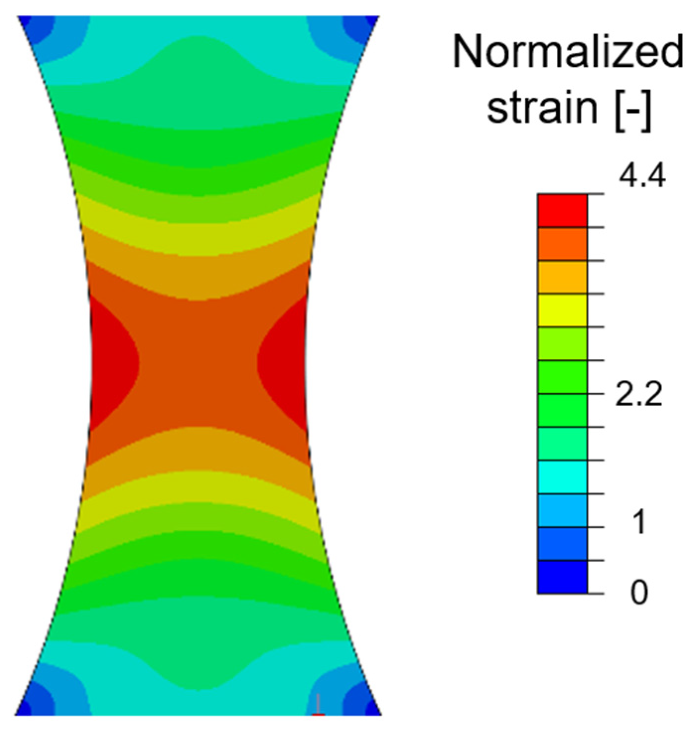
Figure 1. FEM result showing the expected von Mises strain distribution during tensile testing. The strain levels are normalized to highlight the geometrical strain concentration effect.
Metals 14 01175 g001
Figure 2. (a) The X-ray image of the specimen shows two clusters of pores in circles and one pore close to the surface, as indicated by the arrow. (b) Distribution of von Mises strain at a load of 10.0 kN and (c) at a load of 12.8 kN. The X-ray image superimposed on (c) is shown in (d).
Metals 14 01175 g002
Figure 3. The pore with the strain concentration that led to the final fracture. (a) The part of the pore that was found on the fracture surface and (b) the two oxide films at the bottom of the pore merging, showing the top part of the bubble trail with the arrow indicating a wrinkle on the oxide film covering the entire surface.
Metals 14 01175 g003
Figure 4. Analysis of the strain concentration next to the pore (bubble): (a) the overall view of the strain concentration and (b) the young oxide film that drapes over the dendrite tips and intermetallics in the rectangle indicated in (a), with the arrow indicating a wrinkle on the oxide film.
Metals 14 01175 g004
Figure 5. A feature observed on the fracture surface that has been interpreted as the trail of a bubble.
Metals 14 01175 g005
Figure 6. (a) X-ray of the specimen showing many small, dispersed pores, the strain distributions at a load of (b) 10.4 kN, (c) 13.9 kN, and (d) 14.0 kN, and (e) the fracture path.
Metals 14 01175 g006
Figure 7. The fracture surface of the specimen at the point of the dominant strain concentration. (a) area, with the yellow arrows showing many small oxides; (b) details of the white square in (a). (c) Another location within the leading strain concentration and (d) the young bifilms that drape over the dendrite tips and intermetallics (cubes) in the square indicated in (c).
Metals 14 01175 g007
Figure 8. Sludge particles with a thin oxide film draping over them. The wrinkles on the film, as well as a tear in it, are indicated by arrows.
Metals 14 01175 g008
Figure 9. (a) The X-ray of the specimen shows two distinct pores in the specimen. Strain distributions at a load of (b) 9.0 kN and (c) 12.4 kN. (d) The X-ray image in (a) superimposed on the strain distribution in (c). (e) The path of the final fracture.
Metals 14 01175 g009
Figure 10. The large pore near the surface of the specimen that has led to the final fracture.
Metals 14 01175 g010
Figure 11. The cracks observed on the surface of the specimen immediately after fracture. (a) The strain concentration near the minimum cross-sectional area and (b) the more prominent strain concentration near the center of the casting. The black dots are the paint pattern used in the DIC technique for strain distributions.
Metals 14 01175 g011
Table 1. Chemical composition (all in wt.%) of the alloy used in this study.
ElementSiFeCuMnMgCrZnAl
Content10.21.053.140.260.160.040.63Bal
Disclaimer/Publisher’s Note: The statements, opinions and data contained in all publications are solely those of the individual author(s) and contributor(s) and not of MDPI and/or the editor(s). MDPI and/or the editor(s) disclaim responsibility for any injury to people or property resulting from any ideas, methods, instructions or products referred to in the content.