
Impact of Welding Parameters in the Porosity of a Dissimilar Welded Lap Joint of CP800-XPF1000 Steel Weldment by GMAW-P

 ,
,  ,
, 
Abstract
1. Introduction
2. Materials and Methods
2.1. Base Materials
2.2. DOE and Orthogonal Array Experiments
2.3. Welding Procedure
2.4. Microtructural Characterization
2.5. Weld Quality Assesment
2.6. Microhardness Profile Measurements
2.7. Root Test
3. Results
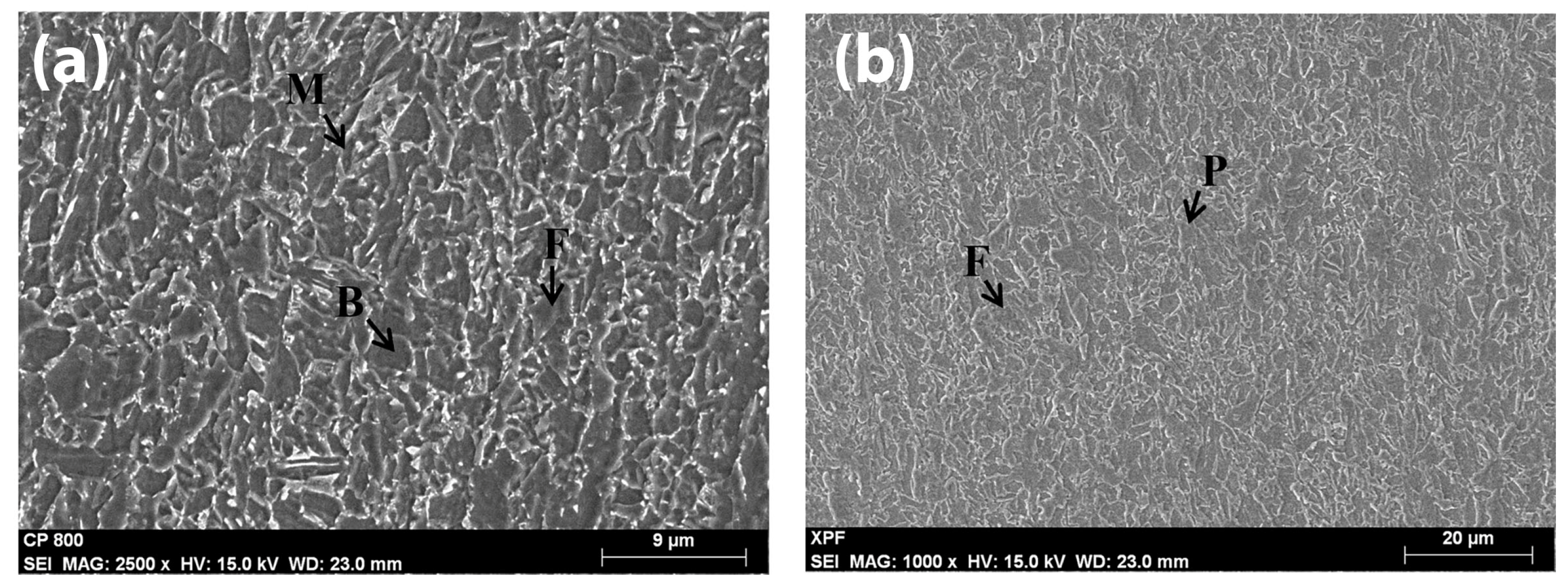
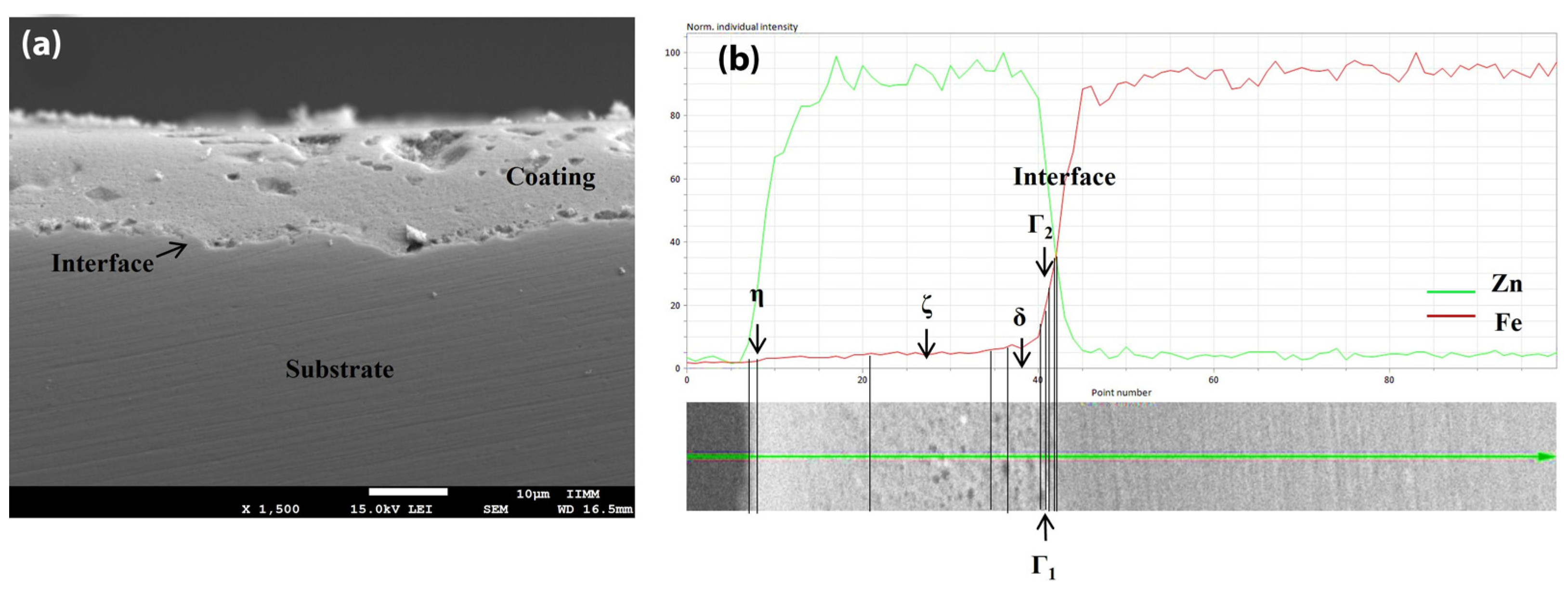
3.1. Base Materials
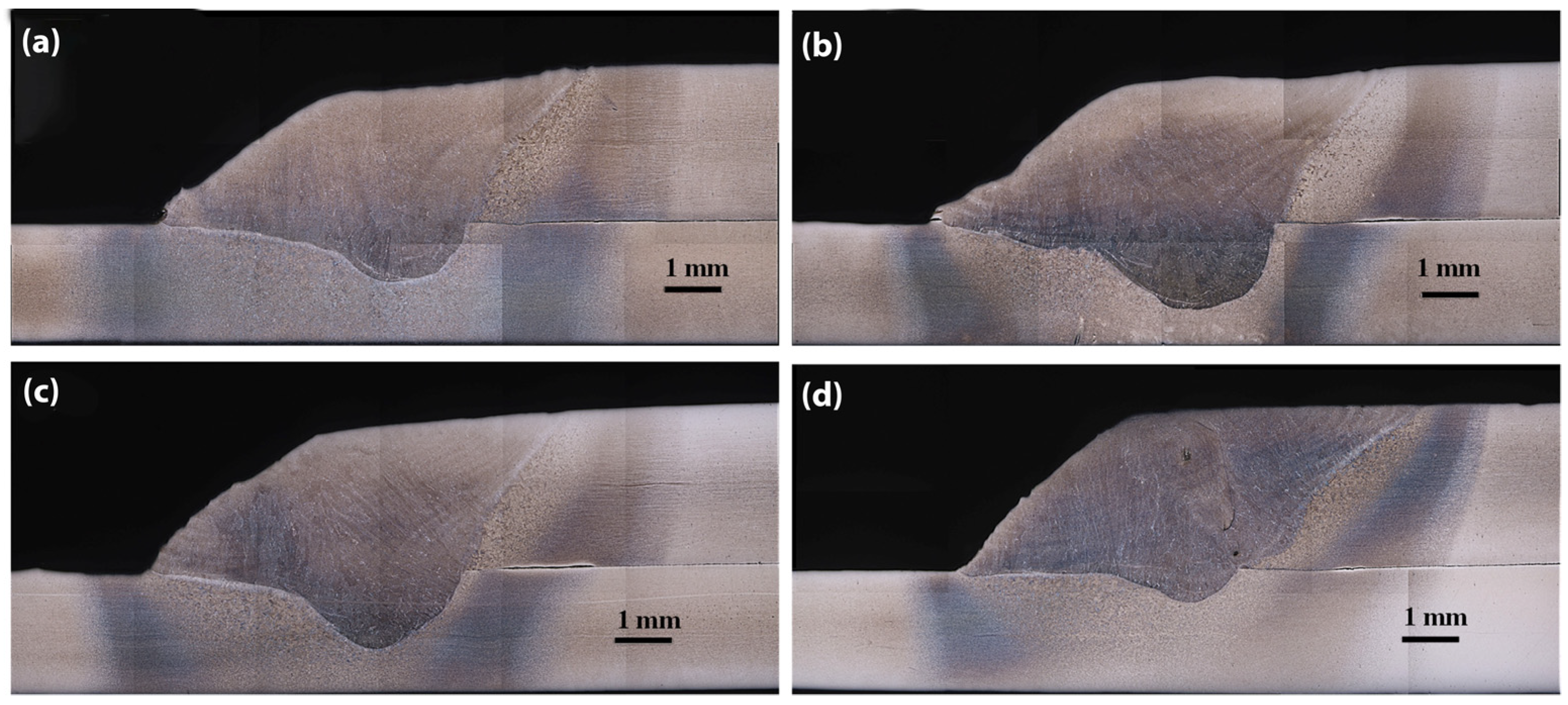
3.2. Weld Quality Assesment
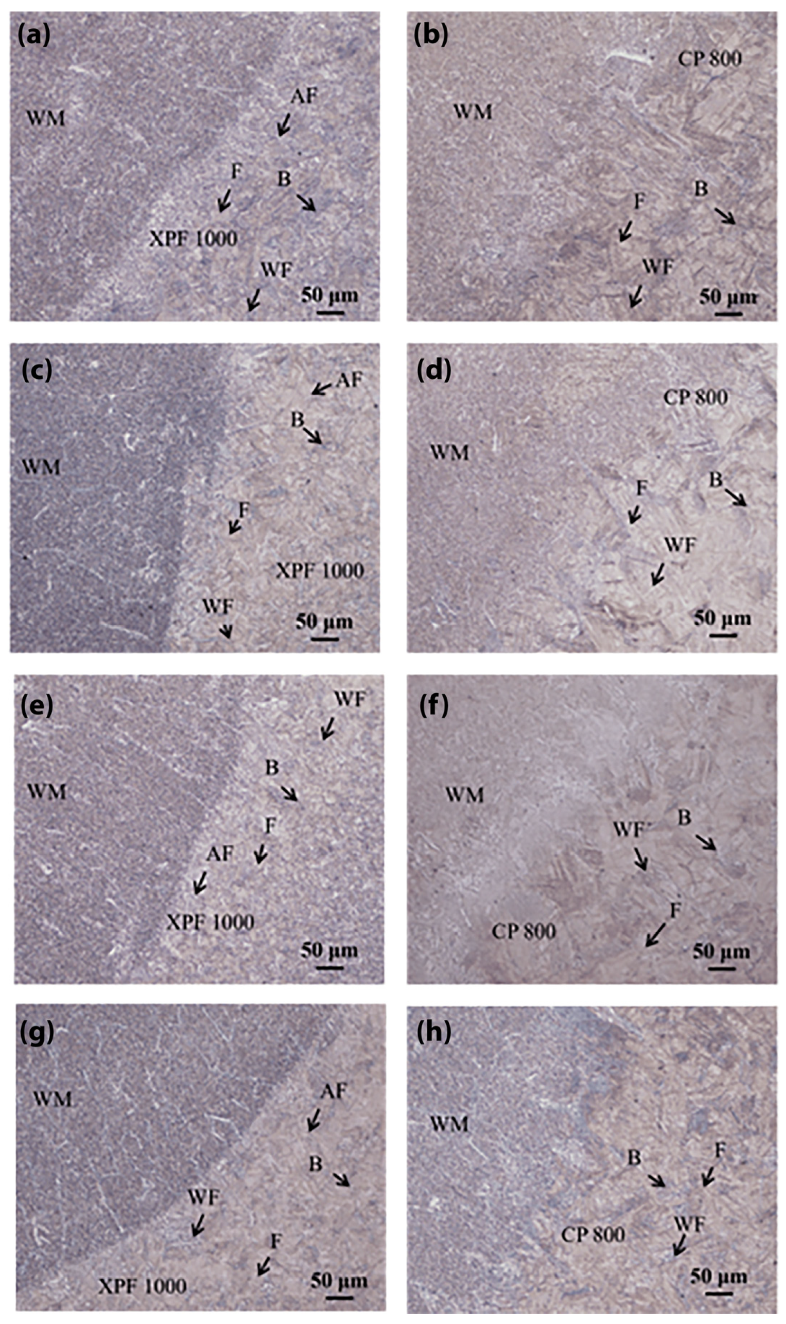
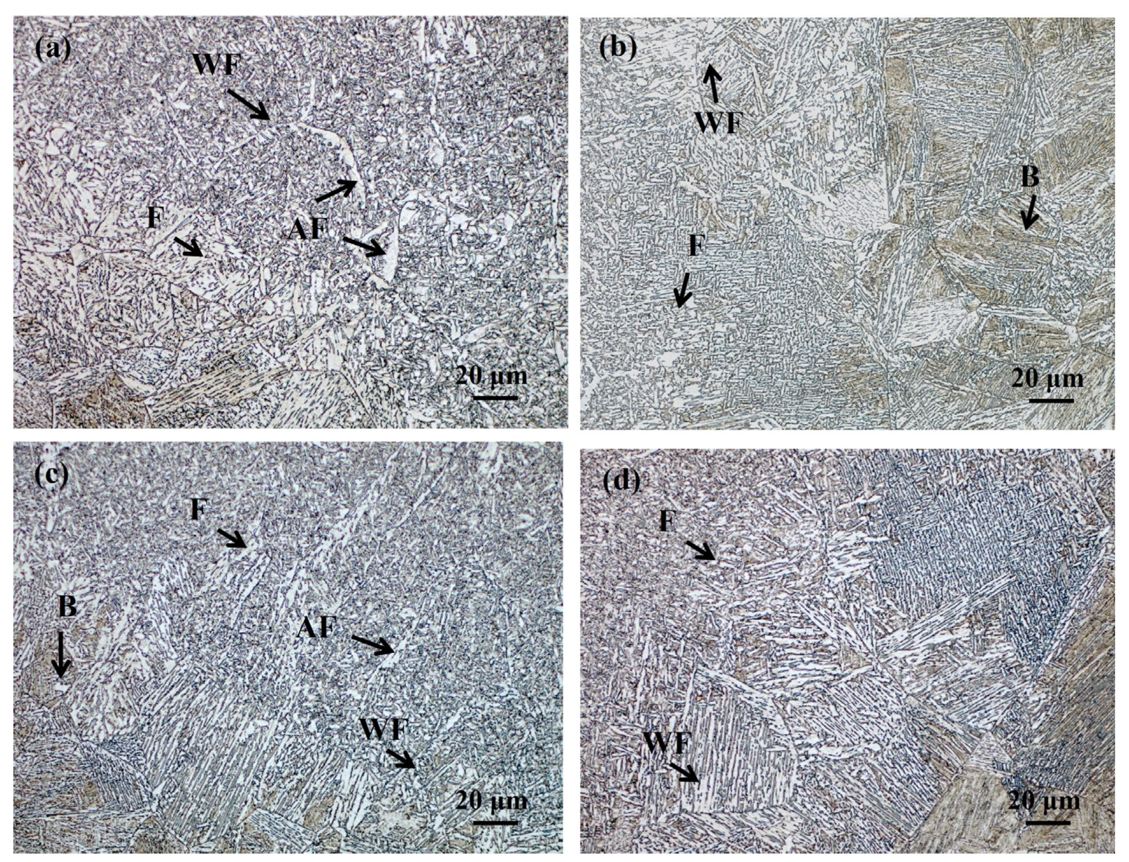
3.3. Microstructural Analisys
3.4. Microhardness Profiles Meassurement
4. Conclusions
Author Contributions
Funding
Data Availability Statement
Acknowledgments
Conflicts of Interest
References
- Hilditch, T.; De Souza, T.; Hodgson, P. Properties and automotive applications of advanced high-strength steels (AHSS). In Welding and Joining of Advanced High Strength Steels (AHSS); Woodhead Publishing: Sawston, UK, 2015; pp. 9–28. [Google Scholar]
- Shome, M. Metal inert gas (MIG) brazing and friction stir spot welding of advanced high-strength steels (AHSS). In Welding and Joining of Advanced High Strength Steels (AHSS); Woodhead Publishing: Sawston, UK, 2015; pp. 137–165. [Google Scholar]
- Shome, M.; Tumuluru, M. Introduction to welding and joining of advanced high-strength steels (AHSS). In Welding and Joining of Advanced High Strength Steels (AHSS); Woodhead Publishing: Sawston, UK, 2015; pp. 1–8. [Google Scholar]
- Demeri, M.Y. Forming of Advanced High-Strength Steels; ASM Handbook 14B Metalworking: Sheet Forming; ASM International: Almere, The Netherlands, 2006. [Google Scholar]
- Korkmaz, E.; Meran, C. Mechanical properties and microstructure characterization of GTAW of micro-alloyed hot rolled ferritic XPF800 steel. Eng. Sci. Technol. Int. J. 2021, 24, 503–513. [Google Scholar] [CrossRef]
- Diniz, P.P.; de Morais, W.A. Impact of welding consumables strength level on metallurgical and mechanical properties homogeneity of welds obtained with a complex phase steel. Unisanta Sci. Technol. 2019, 8, 105–113. [Google Scholar]
- Cho, W.-I.; Na, S.-J.; Thomy, C.; Vollertsen, F. Numerical simulation of molten pool dynamics in high power disk laser welding. J. Mater. Process. Technol. 2012, 212, 262–275. [Google Scholar] [CrossRef]
- Yu, J.; Kim, D. Effects of welding current and torch position parameters on minimizing the weld porosity of zinc-coated steel. Int. J. Adv. Manuf. Technol. 2018, 95, 551–567. [Google Scholar] [CrossRef]
- Izutani, S.; Yamazaki, K.; Suzuki, R. New welding process,“J-solutionTM Zn”, suitable for galvanized steel in the automotive industry. Kobelco Technol. Rev. 2013, 32, 16–23. [Google Scholar]
- Ahsan, M.R.U.; Kim, Y.R.; Kim, C.H.; Kim, J.W.; Ashiri, R.; Park, Y.D. Porosity formation mechanisms in cold metal transfer (CMT) gas metal arc welding (GMAW) of zinc coated steels. Sci. Technol. Weld. Join. 2016, 21, 209–215. [Google Scholar] [CrossRef]
- AWS A5.28/A5.28M:2022; Specification for Low Alloy Steel Electrodes and Rods for Gas Shielded Arc Welding. American Welding Society: Doral, FL, USA, 1996; p. 42.
- Gajbhiye, A.M.; Sonawane, P.R.; Karle, A.H.; Campli, S. Optimization of welding parameters for En8D and SAE1018 materials by Taguchi. Int. J. Interact. Des. Manuf. 2023, 1–10. [Google Scholar] [CrossRef]
- ASTM E165/E165M-18; Standard Practice for Liquid Penetrant Testing for General Industry. ASTM International: Almere, The Netherlands, 2023; p. 19.
- ASTM E1955-20; Standard Radiographic Examination for Soundness of Welds in Steel by Comparison to Graded ASTM Reference Radiographs. ASTM International: Almere, The Netherlands, 2020; p. 3.
- ASTM E384-22; Standard Test Method for Microindentation Hardness of Materials. ASTM International: Almere, The Netherlands, 2022; p. 40.
- AWS D8.7 M:2005; An American National Standard. Recommended Practices for Automotive Weld Quality-Resistance Spot Welding. American Welding Society: Doral, FL, USA, 2005; p. 30.
- Stockburger, E.; Wester, H.; Behrens, B.-A. Failure Modelling of CP800 Using Acoustic Emission Analysis. Appl. Sci. 2023, 13, 4067. [Google Scholar] [CrossRef]
- Venturini, R.; Bianchi, A.; Andraghetti, M.; Guarnaschelli, C.; Cesile, M.; Di Nunzio, P.J.L.M.I. Metallurgical design and production of AHSS grades DP800 and CP800 ISP and ESP thin slab technology at acciaieria arvedi in Cremona, Italy. La Metall. Ital. 2020, 46, 43–51. [Google Scholar]
- Morales-Sánchez, G.; Collazo, A.; Doval-Gandoy, J. Influence of the process parameters on the quality and efficiency of the resistance spot welding process of advanced high-strength complex-phase steels. Metals 2021, 11, 1545. [Google Scholar] [CrossRef]
- David, S.; Babu, S.; Vitek, J. Welding: Solidification and microstructure. J. Miner. Met. Mater. Soc. 2003, 55, 14–20. [Google Scholar] [CrossRef]
- Babu, S.S. The mechanism of acicular ferrite in weld deposits. Curr. Opin. Solid State Mater. Sci. 2004, 8, 267–278. [Google Scholar] [CrossRef]
- Adigun, O.D.; Bodude, M.A.; Adigun, A.R.; Obadele, B.A.; Adebayo, A.O.; Umunakwe, R.; Kolawole, F.O.; Borisade, S.G. Effects of austempering on the microstructure, corrosion and mechanical properties of AISI 1018 steel. Res. Sq. 2021, 1–12. [Google Scholar] [CrossRef]
- Khattak, M.A.; Zaman, S.; Tamin, M.N.; Badshah, S.; Mushtaq, S.; Omran, A.A.B. Effect of welding phenomenon on the microstructure and mechanical properties of ferritic stainless steel-a review. J. Adv. Res. Mater. Sci. 2017, 32, 13–31. [Google Scholar]
- Sekban, D.M.; Aktarer, S.M.; Zhang, H.; Xue, P.; Ma, Z.; Purcek, G. Microstructural and mechanical evolution of a low carbon steel by friction stir processing. Metall. Mater. Trans. A 2017, 48, 3869–3879. [Google Scholar] [CrossRef]
- Otterberg, R.; Sandström, R.; Sandberg, A. Influence of Widmanstätten ferrite on mechanical properties of microalloyed steels. Met. Technol. 1980, 7, 397–408. [Google Scholar] [CrossRef]
- Thewlis, G.; Whiteman, J.; Senogles, D. Dynamics of austenite to ferrite phase transformation in ferrous weld metals. Mater. Sci. Technol. 1997, 13, 257. [Google Scholar] [CrossRef]
- Shin, S.; Rhee, S. Porosity characteristics and effect on tensile shear strength of high-strength galvanized steel sheets after the gas metal arc welding process. Metals 2018, 8, 1077. [Google Scholar] [CrossRef]
- Kah, P.; Suoranta, R.; Martikainen, J. Advanced gas metal arc welding processes. Int. J. Adv. Manuf. Technol. 2013, 67, 655–674. [Google Scholar] [CrossRef]
- Roncery, L.M.; Weber, S.; Theisen, W. Welding of twinning-induced plasticity steels. Scr. Mater. 2012, 66, 997–1001. [Google Scholar] [CrossRef]
- Romero-Orozco, A.J.; Taha-Tijerina, J.J.; De Luna-Alanís, R.; López-Morelos, V.H.; Ramírez-López, M.d.C.; Salazar-Martínez, M.; Curiel-López, F.F. Evaluation of microstructural and mechanical behavior of AHSS CP780 steel welded by GMAW-pulsed and GMAW-pulsed-brazing processes. Metals 2022, 12, 530. [Google Scholar] [CrossRef]


| Material | C | Mn | Si | Cr | Nb | Ti | N | Al | Mo | Ni | Cu | V | Fe |
|---|---|---|---|---|---|---|---|---|---|---|---|---|---|
| CP800 | 0.08 | 1.43 | 0.49 | 0.34 | 0.005 | 0.09 | 0.002 | 0.03 | 0.004 | 0.19 | 0.002 | 0.01 | 91.6 |
| XP1000 | 0.11 | 0.889 | 0.196 | - | 0.044 | 0.1 | - | 0.005 | 0.261 | 0.003 | 0.009 | 0.238 | 92.15 |
| ER80S-D2 | 0.085 | 1.85 | 0.65 | - | - | - | - | - | 0.50 | 0.15 | 0.50 | - | - |
| Zn | Al | Mg | Pb | Sn | Cu | Fe |
|---|---|---|---|---|---|---|
| 99.37 | 0.047 | 0.057 | 0.010 | 0.040 | 0.025 | 0.1 |
| Welding Parameters | Symbol | Level 1 | Level 2 |
|---|---|---|---|
| Frequency pulse | Fp (Hz) | 8 | 5 |
| Peak current | Ip (A) | 98 | 94 |
| Background current | Ib (A) | 87 | 83 |
| Welding Parameters | |||
|---|---|---|---|
| Trial | Frequency Pulse | Peak Current | Background Current |
| Fp (Hz) | Ip (A) | Ib (A) | |
| 1 | 8 | 98 | 87 |
| 2 | 5 | 98 | 83 |
| 3 | 5 | 94 | 87 |
| 4 | 8 | 94 | 83 |
Disclaimer/Publisher’s Note: The statements, opinions and data contained in all publications are solely those of the individual author(s) and contributor(s) and not of MDPI and/or the editor(s). MDPI and/or the editor(s) disclaim responsibility for any injury to people or property resulting from any ideas, methods, instructions or products referred to in the content. |
© 2024 by the authors. Licensee MDPI, Basel, Switzerland. This article is an open access article distributed under the terms and conditions of the Creative Commons Attribution (CC BY) license (https://creativecommons.org/licenses/by/4.0/).
Share and Cite
Garcia-Guerrero, J.C.; Curiel-López, F.F.; López-Morelos, V.H.; Taha-Tijerina, J.J.; Sánchez-Cruz, T.J.; Ramirez-Lopez, M.d.C.; Cortes-Carillo, E.; Quinones-Salinas, M.A. Impact of Welding Parameters in the Porosity of a Dissimilar Welded Lap Joint of CP800-XPF1000 Steel Weldment by GMAW-P. Metals 2024, 14, 309. https://doi.org/10.3390/met14030309
Garcia-Guerrero JC, Curiel-López FF, López-Morelos VH, Taha-Tijerina JJ, Sánchez-Cruz TJ, Ramirez-Lopez MdC, Cortes-Carillo E, Quinones-Salinas MA. Impact of Welding Parameters in the Porosity of a Dissimilar Welded Lap Joint of CP800-XPF1000 Steel Weldment by GMAW-P. Metals. 2024; 14(3):309. https://doi.org/10.3390/met14030309
Chicago/Turabian StyleGarcia-Guerrero, Julio Cesar, Francisco Fernando Curiel-López, Víctor Hugo López-Morelos, Jose Jaime Taha-Tijerina, Teresita Jesus Sánchez-Cruz, Maria del Carmen Ramirez-Lopez, Eduardo Cortes-Carillo, and Miguel Angel Quinones-Salinas. 2024. "Impact of Welding Parameters in the Porosity of a Dissimilar Welded Lap Joint of CP800-XPF1000 Steel Weldment by GMAW-P" Metals 14, no. 3: 309. https://doi.org/10.3390/met14030309
APA StyleGarcia-Guerrero, J. C., Curiel-López, F. F., López-Morelos, V. H., Taha-Tijerina, J. J., Sánchez-Cruz, T. J., Ramirez-Lopez, M. d. C., Cortes-Carillo, E., & Quinones-Salinas, M. A. (2024). Impact of Welding Parameters in the Porosity of a Dissimilar Welded Lap Joint of CP800-XPF1000 Steel Weldment by GMAW-P. Metals, 14(3), 309. https://doi.org/10.3390/met14030309