Article

Improved Discharge Performance of AZ72-0.05La Alloy Anode via Refining Mg17Al12 Phase

1
School of Materials Science and Engineering, Henan University of Science and Technology, Luoyang 471023, China
2
Provincial and Ministerial Co-Construction of Collaborative Innovation Center for Non-Ferrous Metal New Materials and Advanced Processing Technology, Luoyang 471023, China
3
Henan Key Laboratory of Nonferrous Materials Science and Processing Technology, Luoyang 471023, China
4
Longmen Laboratory, Luoyang 471000, China
*
Authors to whom correspondence should be addressed.
Metals 2024, 14(3), 344; https://doi.org/10.3390/met14030344
Submission received: 29 January 2024 / Revised: 13 March 2024 / Accepted: 15 March 2024 / Published: 17 March 2024

Abstract

:
The morphology of phases in magnesium alloys is vitally important for their performance. It is found that improved discharge performance is achieved in AZ72-0.05La alloy via a refining Mg17Al12 phase by means of hot rolling. Before rolling, as-cast AZ72-0.05La alloy has a relatively coarse and strip-like Mg17Al12 phase. After rolling, the Mg17Al12 phase becomes much finer, showing a granulated shape. Due to the refinement of the Mg17Al12 phase, the discharge voltage and energy density of an Mg-air battery with as-rolled AZ72-0.05La alloy as the anode increases by 6% and 3% under a discharge current density of 20 mA·cm−2 in a 3.5% NaCl solution, respectively. The corrosion rate of the as-rolled AZ72-0.05La alloy is slightly larger than the as-cast AZ72-0.05La alloy, but still much lower than as-cast AZ72 alloy. The as-rolled AZ72-0.05La alloy possesses a discharge voltage of 0.74 V and an energy density of 918 mWh·g−1 under a discharge current density of 20 mA·cm−2, and a relatively low corrosion rate of 0.51 mg·cm−2·h−1, demonstrating good overall discharge performance. This work provides a method for improving the discharge performance of Mg-air batteries.

1. Introduction

The rapid consumption of fossil energy and unpredictable price fluctuations have stimulated researchers to actively explore novel green energy sources and efficient energy storage devices [1]. Metal–air batteries, being an emerging green energy source, possess high theoretical energy density that enables them to store more energy and provide a reliable power supply. By developing and utilizing metal–air batteries, we can reduce dependence on fossil fuels while mitigating environmental pollution [2].
Among all the anode materials for metal–air batteries, magnesium exhibits excellent performance due to its favorable recyclability and superior electrochemical properties, including a large theoretical energy density (6.8 kWh·kg−1 [3,4]) and high theoretical voltage (3.1 V [5]). Moreover, magnesium alloys possess the advantages of being lightweight, abundant in resources, easy to process, and environmentally friendly [6]. However, the practical energy density differs significantly from theoretically predicted values [7], primarily because the oxidation product (Mg(OH)2) that adheres to the anode surface reduces the active electrode area and leads to a significant decrease in discharge activity, operating voltage, and the anode utilization rate. Additionally, the negative difference effects of magnesium can cause severe self-corrosion issues such as block effect or hydrogen precipitation during battery discharge, which further reduces the discharge energy density [8,9].
To solve these problems, alloying and plastic deformation (such as extrusion or rolling) are two common and effective methods. Currently, a variety of elements have been added to magnesium alloys, including Al, Zn, Li, Pb, Sn, Ca, and rare earth elements [10,11,12,13,14]. In particular, rare earth (RE) elements are widely used in magnesium alloys, because they can interact with impurity elements (such as Fe, Ni, Co, etc.), promote the purification of alloy melt, and enhance the stability of magnesium alloy surface oxides [15]. Among rare earth elements, La is a cheap and resource-rich choice, and its negative standard electrode potential is close to that of magnesium, which has attracted extensive attention from researchers, and it is found that it has a positive impact on the discharge performance of magnesium anodes [16]. Feng et al. [17] found that adding an La element can improve the discharge activity and corrosion resistance of Mg−6Al−5Pb (AP65) alloy by grain refinement and increasing the number of RE phases in weak cathodes. Song et al. [18] found that adding La led to a more uniform dissolution of Mg-1%Al-0.3%Mn alloy, thereby limiting the occurrence of bulk effects when used as an anode in Mg-air batteries. Therefore, in this study, we choose the commonly used magnesium alloy system Mg-Al-Zn as the research object, and La as the alloying element, specifically Mg-7Al-2Zn-0.05La (AZ72-0.05La) alloy as the research object.
Plastic deformation can optimize microstructure and thus significantly improve the discharge performance of magnesium alloy anodes. For example, Wang et al. [19] showed that annealed and hot-rolled Mg-6Al-5Pb alloy has stronger discharge activity and higher utilization due to the presence of fine grains, a homogeneous magnesium matrix, and fewer crystalline defects. Yang et al. [20] found that the corrosion resistance and discharge performance of Mg-5Li-3Al-1Zn alloy can be improved by rolling due to the enhanced twin density and changed grain orientation. The plastic deformation of magnesium alloys can modify the microstructure of magnesium alloy, thereby significantly enhancing the discharge performance of magnesium alloy anodes. Plastic deformation allows for the avoidance of toxic elements that may be harmful to human health and environment, while retaining the inherent advantages of lightweight magnesium alloys [21]. To investigate the influence of rolling deformation on the electrochemical and discharge performance of anode materials, we selected as-cast AZ72 alloy, as-cast AZ72-0.05La alloy, and as-rolled AZ72-0.05La alloy for comparative studies. Through these experiments, we hope to gain a clearer understanding of the effects of rolling deformation on the performance of magnesium alloys and provide valuable insights into the optimization of magnesium alloy anode materials.

2. Experimental Section

2.1. Anode Preparation

Commercial pure Mg, pure Al, pure Zn, and Mg-30 wt.% La intermediate alloys were heated to approximately 760 °C in a ZGJL0.01-4C-4 medium–frequency induction furnace to melt the Mg-7Al-2Zn and Mg-7Al-2Zn-0.05La alloys. These magnesium alloys are abbreviated to AZ72 and AZ72-0.05La alloys, respectively. Considering that the rare earth La is prone to loss during melting, the La content in the AZ72-0.05La alloy was measured by an inductively coupled plasma emission spectrometer (ICP-OES) after melting, and the test results are shown in Table 1. The melting process was protected by high-purity argon gas to avoid the oxidation of the rare earth elements. The alloy was evenly melted and then poured into a cast iron mold to cool naturally. The as-cast AZ72-0.05La alloy was homogenized at 400 °C for 12 h and cooled in the furnace (~100 °C/h). The homogenized AZ72-0.05La alloy was rolled through multiple rolling passes (each rolling was reduced by about 10%) into a sheet with a final deformation of 50%. After each rolling, the magnesium alloy was reheated at 400 °C for 0.5 h to maintain plasticity and facilitate processing. The samples were processed with wire cutting to obtain the required sample for subsequent testing.

2.2. Microstructure Characterization

The samples were first polished on sandpaper (grade 240-400-800-1000-2000) and then polished with diamond plaster. The surface of the magnesium alloy was eroded using nitrate alcohol (4 mL nitric acid and 96 mL alcohol) to obtain the characteristics of the grains in each sample, which were then observed with an optical microscope. The phase composition of the magnesium alloy was analyzed using an X-ray diffractometer (D8 Advance, Bruker, Ettlingen, Germany). The test conditions included Cu target Kα radiation, tube voltage of 35 kV, current of 40 mA, scanning speed of 2°/min, and scanning range of 15°–85°. The phase composition and elemental distribution analysis were performed using a scanning electron microscope (SEM) in combination with an energy dispersive spectroscopy (EDS) detector (JSM-5610LV, JEOL, Tokyo, Japan). Thermal analysis was conducted using a thermal analyzer (BCZ-TG/DSC-1650, Tianjin Baichuan, Tianjin, China) with a heating rate of 10 °C/min and a dwell time of 20 min.

2.3. Electrochemical Tests and Corrosion Performance Testing

Electrochemical performance analysis was conducted using an electrochemical workstation (PMC2000 1000 500, AMETEK, Pittsburgh, PA, USA). A three-electrode system was utilized, with graphite serving as the auxiliary electrode, a saturated calomel electrode (SCE) as the reference electrode, and a 3.5% NaCl solution as the electrolyte for testing the samples. The sample size was Φ11.3 mm × 5 mm in a cylinder shape. A working electrode with a surface area of 1 cm2 was prepared by coating the alloy sample with epoxy resin. We first sanded and polished the working surface using sandpaper (grades 240-800-1000-2000), then cleaned the working surface with anhydrous ethanol. Before testing, the samples were kept in solution for 3600 s. The scanning rate of the polarization curve was set to 1 mV/s, with a scanning range of −500 mV to 500 mV (vs. OCP). The electrochemical impedance spectroscopy (EIS) data were recorded with a test amplitude of 5 mV at an open circuit potential from 100 kHz to 0.1 Hz. The corrosion rate was assessed by measuring the mass loss of the sample immersed in a 3.5 wt.% NaCl solution at room temperature (25 °C) for 12 h. Additionally, the hydrogen volume of the sample corroded for 12 h was collected in a burette to measure the hydrogen evolution rate.

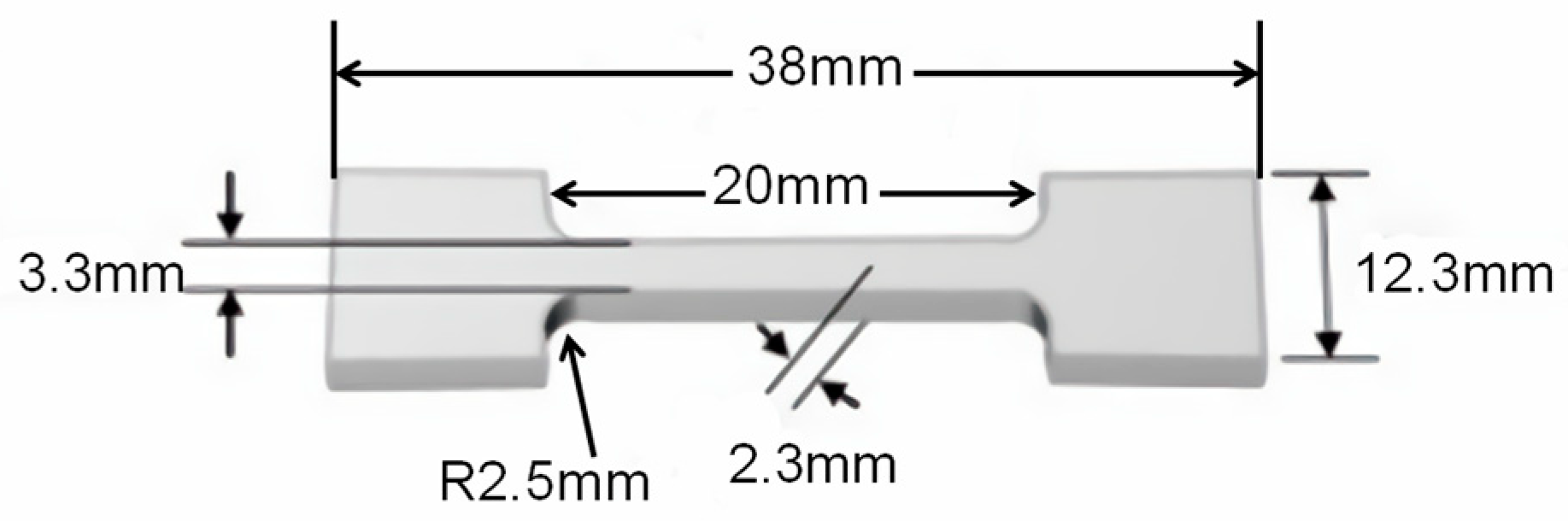
2.4. Mechanical Performance Testing

Vickers hardness testing was conducted using a hardness testing system (HV-10MPTA, Laizhou Veiyee, Laizhou, China). Indentation was performed at the center of the specimens, with a load of 500 g and a dwell time of 15 s. To obtain more reliable data, 7 different points were selected for each specimen, and maximum and minimum values were discarded, leaving 5 remaining values. The average of these 5 values was taken as the hardness value. Tensile performance testing was conducted using a tensile testing machine (UTM6104, Shenzhen Suns Technology, Shenzhen, China), and the tensile rate was set at 0.5 mm/s. The dimensions of the tensile specimen are shown in Figure 1.

2.5. Mg-Air Battery Test

The alloy sample size for the discharge performance test was Φ16 mm × 5 mm. We conducted the discharge experiments in a battery test system (CT-3002AU, Wuhan Landian, Wuhan, China). The samples were weighed before testing and then charged at a current density of 2.5 mA·cm−2, 5 mA·cm−2, 10 mA·cm−2, and 20 mA·cm−2 for 5 h. The air electrode consisted of a catalytic layer, waterproof breathable layer, and collector layer. To maintain constant electrolyte concentration, a solution circulation device was used during testing. After discharge, the magnesium alloy samples were washed by ultrasonic shock in boiled chromic acid solution (1 g AgNO3 + 20 g CrO3 + 100 mL H2O) for 5 min to remove the corrosion products. After removing the corrosion products, the samples were weighed again to calculate the anode utilization efficiency and energy density. After removing the corrosion products, the working surface of the sample was characterized using a scanning electron microscope (JSM-5610LV, JEOL, Tokyo, Japan).
The calculation of the anode utilization efficiency is expressed by Formula (1):
A n o d i c   e f f i c i e n c y % = 3.6 × i × t × A × M a 2 F × w a w b × 100 %
The energy density of the anode is expressed by Formula (2):
S p e c i f i c   c a p a c i t y m A h · g 1 = i × t × A w a w b
where i , A , t , M a , and F are the discharge current density (mA·cm−2), reaction area (cm2), discharge time (h), atomic mass (g·mol−1), and Faraday’s constant (96,485 C·mol−1), respectively. w a and w b are the weights of the magnesium alloys before and after the discharge test.

3. Results and Discussion

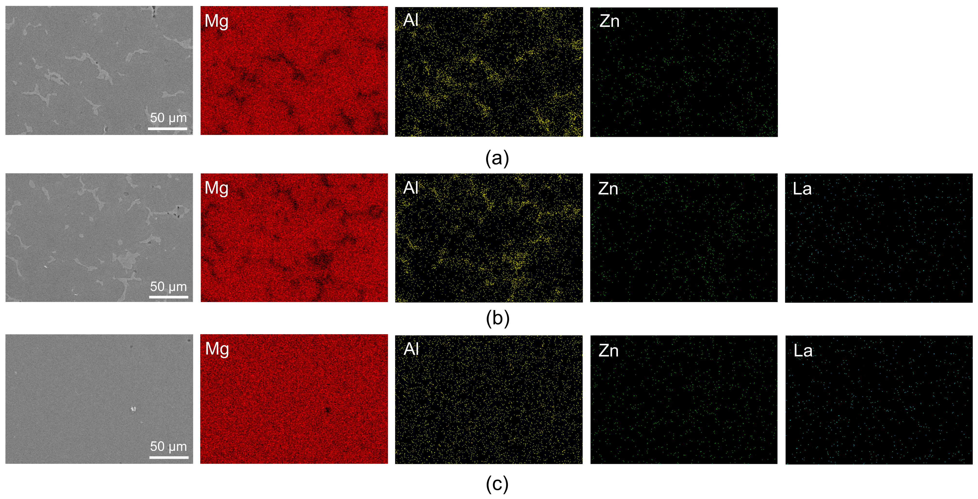
3.1. Microstructure Evolution

The XRD patterns of the magnesium alloys are shown in Figure 2a. The analysis of the XRD patterns revealed that both the AZ72 and AZ72-0.05La alloys are predominantly composed of an α-Mg phase and a β-Mg17Al12 phase. Figure 2b presents the differential scanning calorimetry (DSC) analysis results for the three alloys. As seen in Figure 2b, there is an endothermic peak at ~400 °C, corresponding to the eutectic transformation α-Mg+Mg17Al12→L1. This further confirms that the three alloys primarily consist of an α-Mg phase and a β-Mg17Al12 phase. It is noteworthy that in the study by Wu et al. [23], an Al11La3 phase was detected in the XRD patterns of AZ61-0.5La alloy; however, no new phases were observed after the addition of La in this experiment. This may be due to the relatively small amount of the rare earth La added, meaning that the content of the new phase is below the lower limit of the XRD detection resolution. By using the XRD refinement method, the volume fractions of each phase in the magnesium alloys were estimated. The volume fractions of the β-Mg17Al12 phase in the as-cast AZ72 alloy and AZ72-0.05La alloy were ~4.43% of ~4.68%, respectively. After rolling, the crystal orientation changes significantly. According to the XRD analysis, the peak intensity of (101) on the crystal surface of the magnesium alloy is highest (2θ ≈ 36.619°), and the peak with the highest intensity changed to the (002) plane (2θ ≈ 34.398°) after rolling. Simultaneously, the peak (2θ ≈ 32.193°) corresponding to the (110) crystal plane disappears, indicating that the as-rolled sample has a strong texture. In addition, the diffraction peak of the β-Mg17Al12 phase with a network structure is noticeably weakened after the rolling treatment, indicating a reduction in the content of this phase.
Figure 3 displays the microstructure of the as-cast AZ72 and the as-cast and as-rolled AZ72-0.05La alloys. The microstructure of the as-cast AZ72 and as-cast AZ72-0.05La alloys is primarily dendritic, with the second phase distributed in dendrite gaps and grain boundaries [24]. Figure 3a shows the microstructure of the as-cast AZ72 alloy, in which the magnesium alloy grains show a relatively larger size, and the β-Mg17Al12 phase is discontinuously distributed on the grain boundaries of the α-Mg matrix, forming a discontinuous network structure. The eutectic compounds in the as-cast magnesium alloys show an obvious segregation phenomeon at grain boundaries, resulting in an uneven internal structure. Figure 3b demonstrates the effect of the trace La addition to the as-cast AZ72 alloy in the second phase, β-Mg17Al12. After the trace La addition, the second phase becomes more uniform and refined, laying the foundation for enhancing the discharge voltage and energy density of the battery. Figure 3c illustrates the microstructure of the AZ72-0.05La alloy after rolling. After rolling, the grain boundaries of the AZ72-0.05La alloy become clearer, and the β-Mg17Al12 phase becomes much smaller. The second phase is integrated with the matrix, and the aggregation phenomenon near the grain boundary is significantly weakened, with only a small amount of the second phase remaining in the grain boundary and crystal. This ordered metallographic structure is beneficial to the improvement of the anode discharge performance of AZ72-0.05La [25].
Figure 4 shows the SEM backscattered electron images and corresponding EDS spectra of the as-cast AZ72, as-cast AZ72-0.05La, and as-rolled AZ72-0.05La alloys. It can be observed from Figure 4a,b that the second phase precipitates in a discontinuous network and chain shape along the grain boundaries, and there are some coarse rod-like regions with poor Mg and rich Al, as seen in the EDS spectra. Combined with the XRD and metallographic analysis, these regions correspond to the β-Mg17Al12 phase. Upon addition of the 0.05 wt.% La, the dendritic area increased and became refined, resulting in a more continuous network. Post-rolling, the β-Mg17Al12 phase fractured and dispersed in the alloy in granular form. Additionally, the Zn and La elements were distributed relatively evenly in the alloy, with no obvious segregation observed in the EDS elemental mapping. The decrease in the content of the β-Mg17Al12 phase after rolling is consistent with the results obtained from the metallographic and XRD analysis.

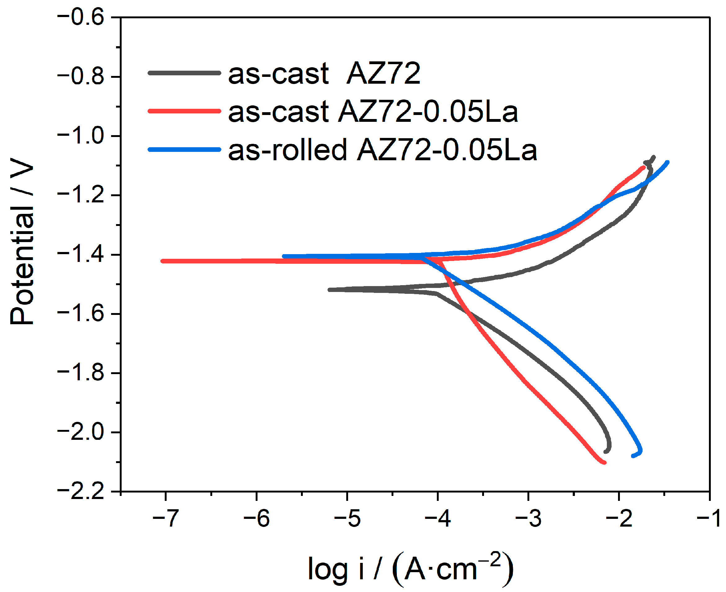
3.2. Electrochemical Properties and Corrosion Resistance

The potentiodynamic polarization (Tafel) curves of the three Mg alloys were tested in a 3.5% NaCl solution, and the results are shown in Figure 5. The relevant corrosion parameters are shown in Table 2. A Tafel curve consists of two parts: the cathode branch and anode branch. The anode branch is mainly related to the dissolution of the magnesium anode, while the cathode branch is mainly related to the hydrogen evolution reduction reaction on the surface of the magnesium anode [26]. The Tafel curve of the anode branch is complicated due to the complexity of anode corrosion behavior. In addition, the Tafel curve of the anode branch is controlled by concentration polarization under the condition of strong polarization, which makes it difficult to analyze the anode branch in detail. The self-corrosion potential (Ecorr) is the metal potential measured in the absence of an impressed current in a particular corrosion system. The more positive the self-corrosion potential, the smaller the corrosion current density, indicating a reduced tendency to corrosion and improved corrosion resistance. As can be seen from Table 2, the corrosion current densities of the as-cast AZ72-0.05La and as-rolled AZ72-0.05La are 155 μA·cm−2 and 205 μA·cm−2, respectively, which are lower than the corrosion current densities (262 μA·cm−2) of the as-cast AZ72 alloy. With a higher volume fraction of the β-Mg17Al12 phase in the as-cast AZ72-0.05La alloy compared with the as-cast AZ72 alloy, the ‘barrier effect’ of the β-Mg17Al12 phase becomes more pronounced after adding 0.05 wt.% La. A higher volume fraction of β-Mg17Al12 is beneficial for hindering the corrosion of α-Mg. In contrast, the as-rolled AZ72-0.05La alloy exhibits a negative shift in corrosion potential and an increase in corrosion current density, indicating decreased corrosion resistance. This is attributed to the deformation of the alloy lattices, leading to stress concentration at the grain boundaries and promoting intergranular corrosion.
The corrosion behavior of the three anode materials was studied using the electrochemical impedance technique. Figure 6 shows the Nyquist diagram, where each EIS measurement includes a high-frequency capacitor loop and a low-frequency loop. The diameter of the high-frequency and low-frequency loops reflects the corrosion resistance of the magnesium alloy, and the large capacitance loop at a high frequency is associated with double electric layer capacitance at the electrode/electrolyte interface and charge transfer process [27]. Comparatively, the as-cast AZ72-0.05La magnesium alloy exhibits better corrosion resistance than the as-cast AZ72 magnesium alloy. Furthermore, the activity of the AZ72-0.05La increases and the corrosion resistance decreases after rolling. To further elucidate the reaction mechanism, the EIS data were fitted with an equivalent circuit using ZsimpWin software (ZsimpWin 3.6, Ann Arbor, MI, USA), as depicted in Figure 6b.
The equivalent circuit in Figure 6b was used to analyze the EIS. The fitting results are shown in Table 3, where Rs is the solution resistance, L and RL correspond to the low-frequency induction loop, and Rct and CPEdl are the charge transfer resistance and double-layer capacitance at the interface between the metal and electrolyte [7]. Rct represents the charge transfer resistance during the electron transfer from a solid (electrode) to a liquid (electrolyte) phase. A larger Rct indicates a lower likelihood of corrosion for the magnesium alloy. RL and L describe an inductive character of impedance found in the fourth quadrant, which is associated with the ion exchange on the anode surface without the cover of film or products. The value of L represents the desorption ability. A larger value of inductance reflects that more areas on the anode surface are not covered by corrosion products, indicating a good desorption ability [27,28]. The as-rolled AZ72-0.05La alloy exhibits the highest value of L, indicating a stronger desorption ability and easier detachment of corrosion products. This helps enhance contact between the Mg and electrolyte, facilitating discharge in a magnesium–air battery. The charge transfer resistance of the as-cast AZ72 and as-cast AZ72-0.05La anodes is 130 Ω·cm2 and 799 Ω·cm2, respectively, and decreases to 330 Ω·cm2 after rolling for the AZ72-0.05La alloy, indicating that the corrosion resistance of the β-Mg17Al12 phase is improved by La microalloying. After rolling, the microstructure of magnesium alloy changes from dendrites to equiaxed crystals, and the preferred corrosion site changes from the β-Mg17Al12 phase to the grain boundary. Grain boundaries are the places in a crystal where different grains meet, with high surface energy and distortion. These unique structures act as active sites and play a crucial role in electrochemical reactions, providing additional sites for reactions and expanding reaction opportunities, thus driving reactions. Therefore, the corrosion resistance of the as-rolled AZ72-0.05La is lower than that of the as-cast AZ72-0.05La alloy.
Figure 7 shows the hydrogen evolution and self-corrosion rates of the three alloys in a 3.5% NaCl solution. The specific parameters are shown in Table 4. There is a potential difference between the β-Mg17Al12 phase and α-Mg matrix, in which the α-Mg matrix and β-Mg17Al12 phase are the anode and cathode, respectively. Galvanic corrosion occurs between the α-Mg matrix and β-Mg17Al12 phase. As depicted in Figure 7, the self-corrosion rate and hydrogen evolution rate of the as-cast AZ72 alloy are 11.12 ± 5.47 mg·cm−2·h−1 and 1.24 ± 0.30 mL·cm−2·h−1, respectively. Upon incorporating 0.05 wt.% La, a significant reduction is observed in the self-corrosion rate and hydrogen evolution rate, measuring 2.70 ± 1.34 mg·cm−2·h−1 and 0.34 ± 0.12 mL·cm−2·h−1. After rolling, the self-corrosion rate and hydrogen evolution rate increases a little to 3.40 ± 1.57 mg·cm−2·h−1 and 0.51 ± 0.24 mL·cm−2·h−1 for the as-rolled alloy, respectively. Notably, the measured values exhibit significant fluctuation, attributed to the relatively heterogeneous microstructure (grain size, β-Mg17Al12 phase, Figure 3 and Figure 4) of the magnesium alloys. The β-Mg17Al12 phase undergoes refinement and homogenization upon introduction of the La element. Simultaneously, the discontinuous strip structure is transformed into a more continuous network structure. This network structure exhibits an enhanced corrosion resistance in a 3.5% NaCl solution, leading to a reduced self-corrosion rate in the magnesium alloy anodes. The addition of the La element also acts as an inhibitor of the NDE (negative difference effect) [29]. After rolling, the second phase undergoes refinement while the grain structure is transformed from dendrites to equiaxed crystals. Deformation leads to an increase in the grain boundary area, enhancing the probability of corrosive medium infiltration into the alloy. Furthermore, the alteration in the grain boundaries may elevate the alloy’s corrosion sensitivity.

3.3. Mechanical Properties

Mechanical performance testing was conducted on the magnesium alloys. From Figure 8a, it can be seen that there is little variation in tensile strength and yield strength between the as-cast AZ72 and as-cast AZ72-0.05La alloys, but there is a significant improvement in elongation. Compared with the as-cast AZ72 and as-cast AZ72-0.05La alloys, the as-rolled AZ72-0.05La alloy exhibits improved yield strength and tensile strength, along with a noticeable enhancement in elongation. The tensile strength, yield strength, and elongation of the as-rolled AZ72-0.05La alloy were 281 MPa, 233 MPa, and 8.50%, respectively. Figure 8b shows the hardness values of the three alloys. The as-cast AZ72 magnesium alloy had a hardness value of 65.34 HV, while the as-cast AZ72-0.05La magnesium alloy and as-rolled AZ72-0.05La alloy had hardness values of 66.60 HV and 77.06 HV, respectively. The addition of a small amount of La to the as-cast AZ72-0.05La alloy resulted in minimal change in hardness compared with the as-cast AZ72 alloy. However, the as-rolled AZ72-0.05La alloy exhibited a significant increase in hardness.
The reasons for the improved strength, elongation, and hardness after rolling are discussed below. During hot rolling, increasing deformation results in a more uniform microstructure in the matrix and a higher recrystallization degree. Refinement of the recrystallized grains, in accordance with the Hall–Petch relationship, contributes to increased strength. Regarding improved elongation, during hot rolling, the recrystallization mechanism undergoes a transition from discontinuous dynamic recrystallization to continuous dynamic recrystallization, greatly consuming the substructure in deformed grains and enhancing the alloy’s plasticity [30].

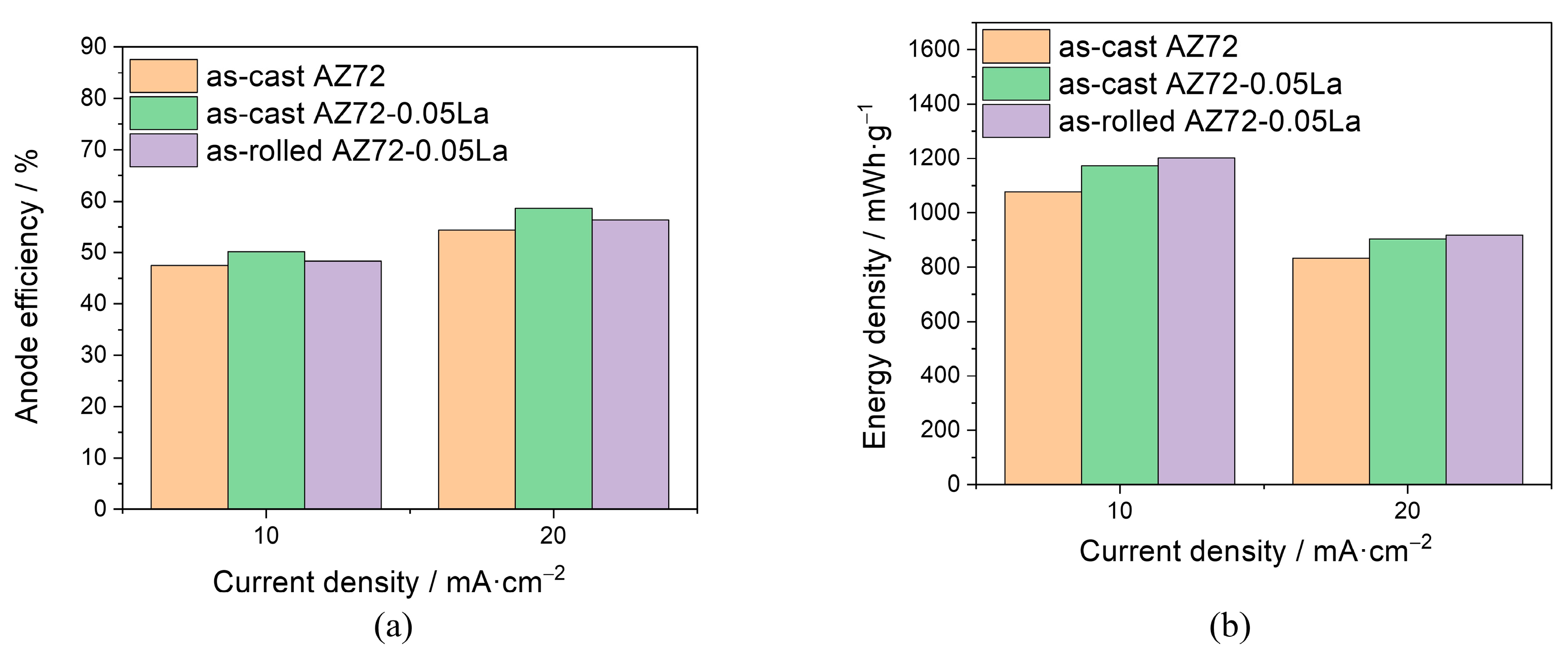
3.4. Discharge Performance of Alloy-Based Anodes

To evaluate the impact of rolling on Mg-air battery performance, three magnesium alloys were employed as anodes and assembled into batteries. Figure 9 depicts the discharge curve of the three magnesium alloy anodes at various current densities in a 3.5 wt % NaCl solution for 5 h. The average discharge voltage is shown in Table 5. The AZ72-0.05La alloys showed excellent performance in terms of battery voltage, which was significantly higher than the AZ72 alloy. At a low current density (2.5 mA·cm−2 as an example), the discharge voltage of the as-cast AZ72 decreases with time, while the discharge voltage of the as-rolled AZ72-0.05La is more stable. At a high current density (20 mA·cm−2 as an example), the as-cast AZ72 showed a trend of continuous decline, and the discharge curve became unstable and zigzagged, while the as-rolled AZ72-0.05La still maintained a high voltage and stable discharge process. During discharge performance testing prior to rolling, the corrosion initiated from the β-Mg17Al12 phase, resulting in non-uniform corrosion. After rolling, the grain boundary becomes more prominent, and corrosion starts from the grain boundary rather than the β-Mg17Al12 phase. Grain boundary corrosion exhibits a higher degree of uniformity compared with β-Mg17Al12 phase corrosion, thus resulting in a more stable discharge performance for the as-rolled AZ72-0.05La alloy. Moreover, the grain boundary represents the junction of different grains inside the crystal, possessing high surface energy and distortion. These special structures and energies are active sites for electrochemical reactions, providing additional reaction sites and increasing reaction opportunities, thus promoting reaction. Therefore, the as-rolled AZ72-0.05La alloy has a higher discharge voltage. For example, at a discharge current density of 20 mA·cm−2, the discharge voltage of the as-rolled AZ72-0.05La is 6% higher than that of the as-cast AZ72-0.05La, respectively, and 9% higher than that of the as-cast AZ72 alloy.
In general, the discharge performance of the AZ72-0.05La alloy anode in both the cast and rolled state is better than that of the as-cast AZ72. It is worth noting that the working voltage of the as-rolled AZ72-0.05La alloy anode is higher than that of other anodes under high discharge current density conditions.
Magnesium–air batteries utilize magnesium or magnesium alloys as anode materials, where the cathode consists of an air electrode, and a neutral salt solution is employed as the electrolyte. The reaction in the neutral electrolyte is represented by Equations (3)–(5).
Anode :   M g 2 e = M g 2 +
Cathode :   1 2 O 2 + H 2 O + 2 e = 2 O H
Overall :   M g + 1 2 O 2 + H 2 O = M g ( O H ) 2
Mg-based anodes suffer from self-corrosion due to the anodic hydrogen reaction (also known as the negative difference effect) [31] chemical step, as follows:
M g + + H 2 O = M g 2 + + O H + 1 2 H 2
This chemical step produces no electrons for the Mg-air battery, leading to poor anodic efficiency and poor discharge capacity. This chemical step is part of the overall Mg corrosion reaction, as shown in Equation (7).
M g + H 2 O = M g ( O H ) 2 + H 2
Figure 10 summarizes the discharge performance parameters at different current densities. Anode utilization efficiency increases with increasing current density; this is due to the fact that self-corrosion occurs as the anode dissolves, and its mass loss is greater than predicted by Faraday’s law at a low current density. As the discharge current density increases, the percentage of the mass loss of the magnesium due to self-corrosion becomes smaller, thus resulting in a dominant anodic reaction [24]. Therefore, at higher current densities, the three anodes exhibit higher anode utilization efficiency. The as-cast AZ72-0.05La alloy showed high anode utilization efficiency at different current densities. In the as-cast AZ72 alloy, the β-Mg17Al12 phase has a large volume fraction, which acts as a barrier and reduces the contact area between the electrolyte and magnesium matrix [32]. In addition, the large volume of β-Mg17Al12 will also have a ‘barrier effect’ during the battery discharge performance test, preventing the corrosion products from falling off [33], which is not conducive to effective magnesium anode discharge. In addition, the large β-Mg17Al12 phase acts as the cathode and reacts with the magnesium matrix to cause local corrosion, so that part of the magnesium matrix is used for self-corrosion [34]. This is the reason for the increase in the anode utilization efficiency and energy density of the as-cast AZ72-0.05La compared with the as-cast AZ72. After rolling, the grain structure is transformed from dendrites to equiaxial crystals, and the discharge process becomes more stable. At the same time, the grain boundary serves as the active site for the electrochemical reaction, providing additional reaction sites and enhancing reaction opportunities, thus promoting the reaction. Owing to the self-corrosion rate of the as-rolled AZ72-0.05La being larger than that of the as-cast AZ72-0.05La alloy (Figure 6), the anode utilization efficiency of the as-rolled AZ72-0.05La is relatively lower than that of the as-cast AZ72-0.05La alloy (Figure 8a). Regarding energy density, increased discharge voltage (Figure 7) leads to higher energy density. For example, at a discharge current density of 20 mA·cm−2, the energy density of the as-rolled AZ72-0.05La is 3% higher than that of the as-cast AZ72-0.05La, and 10% higher than that of the as-cast AZ72 alloy.
Figure 11 shows the surface morphologies of the three anodes after removing the discharge products after 5 h of discharge at a current density of 2.5 mA·cm−2 and 20 mA cm−2. The microstructure of the alloy is closely related to the quantity, morphology and distribution of the second-phase particles. Large and deep holes appear on the surface of the as-cast AZ72 alloy (Figure 11a,d). These holes are formed by the shedding of β-Mg17Al12 during the discharge process. Due to the potential difference between the β-Mg17Al12 phase and α-Mg matrix, where the α-Mg matrix and β-Mg17Al12 phase are anode and cathode, the anode α-Mg matrix in contact with the Mg17Al12 phase tends to dissolve preferentially [35]. After the α-Mg matrix around the β-Mg17Al12 phase dissolves, the β-Mg17Al12 phase loses support and peels off from the α-Mg matrix, resulting in the formation of large corrosion pits. The contact area between the pits and electrolyte increases, the pits continue to expand, and finally large and deep corrosion holes are formed. The as-cast AZ72-0.05La has a relatively smooth corrosion plane (Figure 11b,e), and the disappearance of the large and deep corrosion pits is attributed to the refinement and homogenization of the β-Mg17Al12 by the alloying trace La. For the as-rolled AZ72-0.05La alloy surface, bare leakage areas in most of the Mg matrix were observed (Figure 11c), indicating unhindered and stable dissolution (Figure 11f) [34]. Rolling leads to easier shedding of discharge products from the surface, resulting in more uniform corrosion. This can be attributed to the transformation of the β-Mg17Al12 phase changes from a coarse network to fine particles, and the ‘barrier effect’ is reduced. After rolling, the self-corrosion rate of the AZ72-0.05La alloy increases a little, but the discharge voltage becomes higher and more stable.

4. Conclusions

(1)
The as-cast AZ72-0.05La alloy has a relatively coarse and strip-like β-Mg17Al12 phase, while the β-Mg17Al12 phase becomes much finer and shows a granular state after rolling.
(2)
After rolling, the microstructure of the Mg matrix changes from dendrites to equiaxed crystals. The corrosion of the Mg anode initiates from the β-Mg17Al12 at the grain boundary for the as-cast AZ72-0.05La alloy. After rolling, the corrosion of the Mg anode initiates from the grain boundary, and the discharge activity is enhanced.
(3)
At a high current density of 20 mA·cm−2, the as-rolled AZ72-0.05La alloy has a discharge voltage of 0.74 V and an energy density of 918 mWh·g−1, which are 6% and 3% higher than the as-cast AZ72-0.05La alloy, respectively. In addition, the as-rolled AZ72-0.05La alloy possesses a relatively low corrosion rate of 0.51 mg·cm−2·h−1, showing good comprehensive discharge performance.

Author Contributions

Conceptualization, J.G. and S.A.; methodology, B.W.; software, B.W.; validation, J.G., B.W. and S.A.; formal analysis, J.G.; investigation, B.W.; resources, J.G.; data curation, S.A.; writing—original draft preparation, J.G.; writing—review and editing, S.A.; visualization, B.W.; supervision, S.A.; project administration, J.G.; funding acquisition, J.G. All authors have read and agreed to the published version of the manuscript.

Funding

This work was supported by the Key Scientific Research Project of Colleges and Universities in Henan Province (grant number 18A430013).

Data Availability Statement

The raw data supporting the conclusions of this article will be made available by the authors on request.

Conflicts of Interest

The authors declare no conflicts of interest.

References

  1. Guo, Z.; Qian, G.; Wang, C.; Zhang, G.; Yin, R.; Liu, W.; Liu, R.; Chen, Y. Progress in electrode materials for the industrialization of sodium-ion batteries. Prog. Nat. Sci. Mater. Int. 2023, 33, 1–7. [Google Scholar] [CrossRef]
  2. Ding, D.; Du, Y.; Tang, M.; Bo, S.; Ning, G.; Zhang, H.; Guo, S. Corrosion and discharge behavior of Mg–Zn–Mn–Nd alloys as primary Mg–air batteries anode. Trans. Nonferrous Met. Soc. China 2023, 33, 2014–2029. [Google Scholar] [CrossRef]
  3. Deng, M.; Wang, L.; Vaghefinazari, B.; Xu, W.; Feiler, C.; Lamaka, S.; Hoeche, D.; Zheludkevich, M.; Snihirova, D. High-energy and durable aqueous magnesium batteries: Recent advances and perspectives. Energy Storage Mater. 2021, 43, 238–247. [Google Scholar] [CrossRef]
  4. Xiong, H.; Yu, K.; Yin, X.; Dai, Y.; Yan, Y.; Zhu, H. Effects of microstructure on the electrochemical discharge behavior of Mg-6wt% Al-1wt% Sn alloy as anode for Mg-air primary battery. J. Alloys Compd. 2017, 708, 652–661. [Google Scholar] [CrossRef]
  5. Huang, Z.; Huang, R.; Pei, Y.; Gao, X.; Jiang, L.; Zou, J. Effect of Rolling Deformation on Corrosion and Discharge Behavior of AZ91 Magnesium Alloy. Adv. Eng. Mater. 2023, 25, 2200890. [Google Scholar] [CrossRef]
  6. Wang, N.; Mu, Y.; Xiong, W.; Zhang, J.; Li, Q.; Shi, Z. Effect of crystallographic orientation on the discharge and corrosion behavior of AP65 magnesium alloy anodes. Corros. Sci. 2018, 144, 107–126. [Google Scholar] [CrossRef]
  7. Chen, X.; Liu, X.; Le, Q.; Zhang, M.; Liu, M.; Atrens, A. A comprehensive review of the development of magnesium anodes for primary batteries. J. Mater. Chem. A 2021, 9, 12367–12399. [Google Scholar] [CrossRef]
  8. Deng, M.; Wang, L.; Höche, D.; Lamaka, S.V.; Jiang, P.; Snihirova, D.; Scharnagl, N.; Zheludkevich, M.L. Ca/In micro alloying as a novel strategy to simultaneously enhance power and energy density of primary Mg-air batteries from anode aspect. J. Power Sources 2020, 472, 228528. [Google Scholar] [CrossRef]
  9. Gu, X.; Cheng, W.; Cheng, S.; Liu, Y.; Wang, Z.; Yu, H.; Cui, Z.; Wang, L.; Wang, H. Tailoring the microstructure and improving the discharge properties of dilute Mg-Sn-Mn-Ca alloy as anode for Mg-air battery through homogenization prior to extrusion. J. Mater. Sci. Technol. 2021, 60, 77–89. [Google Scholar] [CrossRef]
  10. Xiong, H.; Zhu, H.; Luo, J.; Yu, K.; Shi, C.; Fang, H.; Zhang, Y. Effects of heat treatment on the discharge behavior of Mg-6wt.% Al-1wt.% Sn alloy as anode for magnesium-air batteries. J. Mater. Eng. Perform. 2017, 26, 2901–2911. [Google Scholar] [CrossRef]
  11. Liu, X.; Xue, J.; Zhang, P.; Wang, Z. Effects of the combinative Ca, Sm and La additions on the electrochemical behaviors and discharge performance of the as-extruded AZ91 anodes for Mg-air batteries. J. Power Sources 2019, 414, 174–182. [Google Scholar] [CrossRef]
  12. Ma, J.; Wang, G.; Li, Y.; Ren, F.; Volinsky, A. Electrochemical performance of Mg-air batteries based on AZ series magnesium alloys. Ionics 2019, 25, 2201–2209. [Google Scholar] [CrossRef]
  13. Yang, H.; Wu, L.; Jiang, B.; Liu, W.; Song, J.; Huang, G.; Zhang, D.; Pan, F. Clarifying the roles of grain boundary and grain orientation on the corrosion and discharge processes of α-Mg based Mg-Li alloys for primary Mg-air batteries. J. Mater. Sci. Technol. 2021, 62, 128–138. [Google Scholar] [CrossRef]
  14. Pechberty, C.; Klein, A.; Fraisse, B.; Stievano, L.; Berthelot, R. Mechanisms of electrochemical magnesium (de) alloying of Mg-Sn and Mg-Pb polymorphs. J. Magnes. Alloys 2022, 10, 1609–1616. [Google Scholar] [CrossRef]
  15. Zhang, G.; Luo, Z.; Zhang, H.; Chu, R. Ignition-proof mechanism of magnesium alloy added with rare earth La from first-principle study. J. Rare Earths 2012, 30, 573–578. [Google Scholar] [CrossRef]
  16. Ma, B.; Tan, C.; Ouyang, L.; Shao, H.; Wang, N.; Zhu, M. Microstructure and discharge performance of Mg-La alloys as the anodes for primary magnesium-air batteries. J. Alloys Compd. 2022, 918, 165803. [Google Scholar] [CrossRef]
  17. Feng, Y.; Lei, G.; He, Y.; Wang, R.; Wang, X. Discharge performance of Mg-Al-Pb-La anode for Mg-air battery. Trans. J. Nonferrous Met. Soc. 2018, 28, 2274–2286. [Google Scholar] [CrossRef]
  18. Song, Y.; Su, D.; Yang, Q.; Yuan, M.; Jiang, B.; Jiang, L.; Pan, F. Micro-alloyed mg-Al-Mn-La anode for mg-air batteries. J. Electrochem. Soc. 2021, 168, 090526. [Google Scholar] [CrossRef]
  19. Wang, N.; Wang, R.; Peng, C.; Feng, Y.; Chen, B. Effect of hot rolling and subsequent annealing on electrochemical discharge behavior of AP65 magnesium alloy as anode for seawater activated battery. Corros. Sci. 2012, 64, 17–27. [Google Scholar] [CrossRef]
  20. Yang, H.; Wu, L.; Jiang, B. Enhancement of corrosion resistance and discharge performance of Mg–5Li–3Al–1Zn sheet for Mg-air battery via rolling. J. Electrochem. Soc. 2020, 167, 110529. [Google Scholar] [CrossRef]
  21. Li, Q.; Ye, W.; Gao, H.; Gao, L. Improving the corrosion resistance of ZEK100 magnesium alloy by combining high-pressure torsion technology with hydroxyapatite coating. Mater. Des. 2019, 181, 107933. [Google Scholar] [CrossRef]
  22. An, S.; Liu, X.; Wang, Z.; Ren, F. Effect of rare earth lanthanum on corrosion and electrochemical properties of Mg-7Al-2Zn magnesium alloy anode. J. Henan Univ. Sci. Technol. (Nat. Sci.) 2023, 44, 17–24. [Google Scholar]
  23. Wu, Y.; Wang, Z.; Liu, Y.; Li, G.; Xie, S.; Yu, H.; Xiong, H. AZ61 and AZ61-La alloys as anodes for Mg-air battery. J. Mater. Eng. Perform. 2019, 28, 2006–2016. [Google Scholar] [CrossRef]
  24. Zhang, J.; Li, Z.; Guo, Z.; Pan, F. Solidification microstructural constituent and its crystallographic morphology of permanent-mould-cast Mg-Zn-Al alloys. Trans. Nonferrous Met. Soc. China 2006, 16, 452–458. [Google Scholar] [CrossRef]
  25. Li, Z.; Gu, X.; Lou, S.; Zheng, Y. The development of binary Mg-Ca alloys for use as biodegradable materials within bone. Biomaterials 2008, 29, 1329–1344. [Google Scholar] [CrossRef]
  26. Fan, L.; Lu, H. The effect of grain size on aluminum anodes for Al-air batteries in alkaline electrolytes. J. Power Sources 2015, 284, 409–415. [Google Scholar] [CrossRef]
  27. Chen, X.; Zou, Q.; Le, Q.; Hou, J.; Guo, R.; Wang, H.; Hu, C.; Bao, L.; Wang, T.; Zhao, D. The quasicrystal of Mg-Zn-Y on discharge and electrochemical behaviors as the anode for Mg-air battery. Power Sources 2020, 451, 227807. [Google Scholar] [CrossRef]
  28. Chen, X.; Ning, S.; Le, Q.; Wang, H.; Zou, Q.; Guo, R.; Hou, J.; Jia, Y.; Atrens, A.; Yu, F. Effects of external field treatment on the electrochemical behaviors and discharge performance of AZ80 anodes for Mg-air batteries. Mater. Sci.Technol. 2020, 38, 47–55. [Google Scholar] [CrossRef]
  29. Song, Y.; Yao, K.; Zou, Q.; Yang, Q.; Jiang, B.; Wang, L.; Yuan, M.; Wang, Q.; Huang, G.; Pan, F. Processing micro-alloyed Mg-la binary alloy into a high-performance Mg-air battery anode via extrusion. J. Electrochem. Soc. 2022, 169, 020575. [Google Scholar] [CrossRef]
  30. Jiang, M.; Yan, H.; Chen, R. Microstructure, texture and mechanical properties in an as-cast AZ61 Mg alloy during multi-directional impact forging and subsequent heat treatment. Mater. Des. 2015, 87, 891–900. [Google Scholar] [CrossRef]
  31. Chen, X.; Jia, Y.; Shi, Z.; Le, Q.; Li, J.; Zhang, M.; Liu, M.; Atrens, A. Understanding the discharge behavior of an ultra-high-purity Mg anode for Mg-air primary battery. J. Mater. Chem. A 2021, 9, 21387–21401. [Google Scholar] [CrossRef]
  32. Jin, Z.; Cheng, X.; Zha, M.; Rong, J.; Zhang, H.; Wang, J.; Wang, C.; Li, Z.; Wang, H. Effects of Mg17Al12 second phase particles on twinning-induced recrystallization behavior in Mg–Al–Zn alloys during gradient hot rolling. J. Mater. Sci. Technol 2019, 35, 2017–2026. [Google Scholar] [CrossRef]
  33. Al Bacha, S.; Aubert, I.; Devos, O.; Zakhour, M.; Nakhl, M.; Bobet, J.-L. Corrosion of pure and milled Mg17Al12 in “model” seawater solution. Int. J. Hydrogen Energy 2020, 45, 15805–15813. [Google Scholar] [CrossRef]
  34. Song, Y.; Ma, J.; Li, Y.; Wang, G.; Qin, C.; Stock, H.-R. Effects of second phases in anode materials on discharge performance of Mg-air batteries. Ionics 2019, 25, 5899–5906. [Google Scholar] [CrossRef]
  35. Chen, X.; Wang, H.; Le, Q.; Jia, Y.; Zhou, X.; Yu, F.; Atrens, A. The role of long-period stacking ordered phase on the discharge and electrochemical behaviors of magnesium anode Mg-Zn-Y for the primary Mg-air battery. Int. J. Energy Res. 2020, 44, 8865–8876. [Google Scholar] [CrossRef]
Figure 1. Tensile specimen dimensions.
Metals 14 00344 g001
Figure 2. (a) XRD patterns and (b) DSC heating curves of the three magnesium alloys.
Metals 14 00344 g002
Figure 3. Metallographic photos of (a) as-cast AZ72 alloy, (b) as-cast AZ72-0.05La alloy, and (c) as-rolled AZ72-0.05La alloy.
Metals 14 00344 g003
Figure 4. SEM morphologies and EDS elemental mapping. (a) as-cast AZ72 alloy, (b) as-cast AZ72-0.05La alloy, and (c) as-rolled AZ72-0.05La alloy.
Metals 14 00344 g004
Figure 5. Polarization curves of three magnesium alloys in 3.5 wt.% NaCl solution.
Metals 14 00344 g005
Figure 6. (a) EIS in Nyquist plots of three magnesium alloys in 3.5 wt% NaCl solution, (b) Equivalent circuit for fitting the EIS.
Metals 14 00344 g006
Figure 7. Corrosion rate and hydrogen evolution rate.
Metals 14 00344 g007
Figure 8. (a) Room temperature mechanical properties (b) Hardness performance.
Metals 14 00344 g008
Figure 9. Discharge curves of the investigated anodes in 3.5 wt % NaCl solution at current density of: (a) 2.5 mA·cm−2, (b) 5 mA·cm−2, (c) 10 mA·cm−2, (d) 20 mA·cm−2.
Metals 14 00344 g009
Figure 10. Discharge performance of assembled Mg-air batteries with different anodes: (a) Anodic efficiency, (b) Energy density.
Metals 14 00344 g010
Figure 11. The surface morphologies of as-cast AZ72 (a,d), as-cast AZ72-0.05La (b,e), and as-rolled AZ72-0.05La (c,f) alloy after the removal of discharge products. The experiments were conducted in a 3.5 wt% NaCl solution for 5 h, with discharge current density of 2.5 mA·cm−2 (ac) and 20 mA·cm−2 (df).
Metals 14 00344 g011
Table 1. Chemical composition of the experimental alloys (wt.%) (Adapted from Ref. [22]).
AlloysAlZnLaMg
AZ729.4702.1520.000Bal.
AZ72-0.05La8.5661.8310.043Bal.
Table 2. OCP stability value and polarization curve fitting results.
SampleEcorr/VIcorr/μA·cm−2
as-cast AZ72−1.52262
as-cast AZ72-0.05La−1.42155
as-rolled AZ72-0.05La−1.41205
Table 3. The results of fitting EIS based on the equivalent circuit of Figure 5.
SampleRs/Ω·cm−2CPEdl/F·cm−2n1Rct/Ω·cm2L/H·cm2RL/Ω·cm2χ2/10−3
as-cast AZ7215.310.23 × 10−60.93130.3047.70128.806.30
as-cast AZ72-0.05La9.848.79 × 10−60.94799.10322.20735.0014.00
as-rolled AZ72-0.05La9.058.90 × 10−60.93330.60392.60734.7017.70
Table 4. Corrosion rate and hydrogen evolution rate.
Corrosion ParametersAs-Cast AZ72As-Cast AZ72-0.05LaAs-Rolled AZ72-0.05La
Corrosion rate/mg·cm−2·h−111.12 ± 5.472.70 ± 1.343.40 ± 1.57
Hydrogen evolution rate/mL·cm−2·h−11.24 ± 0.300.34 ± 0.120.51 ± 0.24
Table 5. Average discharge voltage of the Mg-air battery using three different magnesium alloys as anodes.
Current Density (mA cm−2)As-Cast AZ72As-Cast AZ72-0.05LaAs-Rolled AZ72-0.05La
Average discharge voltage (V)2.51.3401.3231.350
51.1281.2431.280
101.0091.0641.136
200.6810.7030.742
Disclaimer/Publisher’s Note: The statements, opinions and data contained in all publications are solely those of the individual author(s) and contributor(s) and not of MDPI and/or the editor(s). MDPI and/or the editor(s) disclaim responsibility for any injury to people or property resulting from any ideas, methods, instructions or products referred to in the content.

