Article

A Full-Field Crystal Plasticity Study on the Bauschinger Effect Caused by Non-Shearable Particles and Voids in Aluminium Single Crystals

Department of Materials Science and Engineering, Faculty of Natural Sciences, Norwegian University of Science and Technology, N-7491 Trondheim, Norway
*
Author to whom correspondence should be addressed.
Metals 2024, 14(4), 424; https://doi.org/10.3390/met14040424
Submission received: 6 March 2024 / Revised: 25 March 2024 / Accepted: 27 March 2024 / Published: 3 April 2024
(This article belongs to the Section Computation and Simulation on Metals)

Abstract

:
In the present work, the goal is to use two-scale simulations to be incorporated into the full-field open software DAMASK version 2.0.3 crystal plasticity framework, in relation to the Bauschinger effect caused by the composite effect of the presence of second-phase particles with surrounding deformation zones. The idea is to achieve this by including a back stress of the critical resolved shear stress in a single-phase simulation, as an alternative to explicitly resolving the second-phase particles in the system. The back stress model is calibrated to the volume-averaged behaviour of detailed crystal plasticity simulations with the presence of hard, non-shearable spherical particles or voids. A simplified particle-scale model with a periodic box containing only one of the spherical particles in the crystal is considered. Applying periodic boundary conditions corresponds to a uniform regular distribution of particles or voids in the crystal. This serves as an idealised approximation of a particle distribution with the given mean size and particle volume fraction. The Bauschinger effect is investigated by simulating tensile–compression tests with 5% and 10% volume fractions of particles and with 1%, 2%, and 5% pre-strain. It is observed that an increasing volume fraction increases the Bauschinger effect, both for the cases with particles and with voids. However, increasing the pre-strain only increases the Bauschinger effect for the case with particles and not for the case with voids. The model with back stress of the critical resolved shear stress, but without the detailed particle simulation, can be fitted to provide reasonably close results for the volume-averaged response of the detailed simulations.

1. Introduction

The presence of either second-phase particles or voids will, in various ways, influence the strength and work hardening of an alloy. The Bauschinger effect, which involves a decrease in yield stress when the load direction is reversed, occurs at many strain scales and via different mechanisms in metals. One can distinguish various local dislocation mechanisms from the simple composite effect of the inclusion and the surrounding deformation zone that is considered here.
Cases with the presence of many small particles or voids will have the strongest impact through their direct influence as pinning points for gliding dislocations. Voids or particles that are larger than 3–4 nm will act as strong pinning points for dislocations [1]. Submicron-sized particles that are non-shearable may lead to the generation and recovery of geometrical necessary dislocations (GNDs) during plastic deformation. Local dislocation mechanisms involve the polarisation of dislocation structures. The simplest examples are the pile-up of the Orowan type of shear loops around non-shearable particles, see, e.g., [2], or the emission and corresponding pile-up of prismatic loops [3,4,5,6,7,8,9,10,11,12]. In both cases, the loops are, in principle, reversible on strain reversals, as far as the dislocation glide is reversible, i.e., at small strains at sufficiently low temperatures. A simple picture is a shear loop around a particle formed during forward deformation and being annihilated when the dislocation glides back again. The pinning from these particles is, consequently, absent right after a deformation reversal. However, after some reverse straining, the loops are removed and, oppositely, dislocation loops are formed, increasing the stress again. For larger particles, deformation zones with higher dislocation densities are formed locally around the particles [13].
These effects can be incorporated into crystal plasticity models at two different scales. With a high spatial resolution, the detailed crystal deformation around each particle can be resolved. However, detailed dislocation mechanisms, like the emission of prismatic loops, and the corresponding deformation at the local inclusion scale, are not accounted for in the standard crystal plasticity models, which lack a parameter that controls the length scale of the appropriate dislocation mechanism [14], i.e., that the model provides within a scaling, similar solutions for large and small particles, based on plastic deformation caused by dislocation glide. To some extent, the small-scale dislocation effects can be accounted for by strain gradient (crystal) plasticity models, see, e.g., [15]. Alternatively, crystal plasticity models are formulated for a homogenised, representative, mesoscale volume element that contains a statistically representative number of particles or voids. In such models, the influence of geometrically necessary dislocations can be dealt with using models for the critical resolved shear stress or using the eigenstrain representation of the Orowan looping [16]. Such models are based on specific dislocation mechanisms, like prismatic loops, and include kinematic hardening of the critical resolved shear stress for reverse slip systems see, e.g., [17,18,19,20].
For particles or voids that are typically larger than about one micron, the dislocation interactions are more complex, resulting in the generation and movement of secondary dislocations [13] and a corresponding deformation zone around the inclusion. This behaviour can be reasonably well modelled, at the local scale, using classical crystal plasticity models. However, a detailed spatial resolution of particles is not possible with existing computers. Therefore, the current work is an attempt to model a periodic array of particles in a representative volume and apply the simulation results in a first attempt to calibrate a model for the evolution of the critical resolved shear stress in a crystal plasticity model at the mesoscale.
Brown and Clarke [5] compared a composite modelling approach with the observed hardening for a variety of systems and concluded that the calculated work-hardening rates were qualitatively in agreement with experiments, but systematically smaller. This is reasonable since the deformation zones around the particles are not accounted for. Bate et al. [21] attempted an elastic inclusions crystal plasticity. Incorporation of the inclusion model into CPFEM was conducted by Han et al. [22,23].
Recently, more computer capacity has become available, allowing three-dimensional simulations. A number of studies address the simulation of particle distributions contained in a statistically similar representative volume element (SSRVE). Asgharzadeh et al. [24] used the CPFEM modelling technique to include half a million second-phase particles, but with only one integration point each, to simulate a tensile test of low-carbon steel. However, their use of a high-resolution CPFEM to model the influence of the particles can hardly be justified, as it was conducted without the spatial resolution of each particle and without GND mechanisms that would be expected for submicron secondary particles. Umar et al. [25] used the DAMASK software for two-dimensional simulations of an SSRVE with cementite in spheroidised medium-carbon steels. Qayyum et al. [26] discussed how to efficiently use as coarse a resolution as possible and thin three-dimensional RVEs to save computing time for particle distributions. An example of three-dimensional SSRVE simulations is the work on TRIP steels and Zirconia composites by Ali et al. [27]. However, only single-element resolution is used for the inclusions.
Simulating, in detail, the second-phase particles using full-field methods is computationally expensive and only a small number of such studies exist. An early two-dimensional simulation of plane strain compression was performed by Bate [14], who simulated the detailed deformation zone around a single particle. Sedighiani et al. [28] calculated the deformation zone around a particle as an example to test re-meshing strategies with the DAMASK software. Otherwise, to the authors’ best knowledge, there are no detailed three-dimensional simulation studies using a spectral solver for studying the Bauschinger effect caused by arrays of particles/voids in metals.
Aimed at full-field crystal plasticity simulations of a polycrystalline material with second-phase inclusions, one, in principle, has to consider a polycrystal with a large (representative) number of grains of different orientations and, within each grain, a distribution of particles, with an average inclusion size, which is generally much smaller than the grain size. To properly account for the grain–grain interactions, as well as the matrix–particle interactions, and their effect on the crystal plasticity behaviour (including the Bauschinger effect) would require a discretisation and system size (# simulation volume elements), which is far beyond current computer capabilities (both in terms of data storage and simulation time). Currently, to address this problem, significant simplifications are needed.
In the present work, the spectral solver of the crystal plasticity open software model DAMASK version 2.0.3 is used to investigate the Bauschinger effect caused by hard, non-shearable particles and voids. In the simulations, we consider a single spherical particle embedded in an fcc crystal matrix with properties similar to an aluminium alloy. As the spectral solver of DAMASK assumes periodic boundary conditions, this setup corresponds to a representative volume element (RVE) within a crystal (or grain) consisting of a regular array of inclusions of a certain size and volume fraction. In principle, the yield surface and the plastic response of the crystal containing the particles can be probed by such calculations. However, only tensile–compression tests along the [100]-direction are considered in the current investigation and a model (also available in DAMASK) with kinematic hardening of the slip systems is calibrated to these tests only, which is assumed to capture the Bauschinger behaviour.
Using the (standard) phenomenological model of DAMASK, the Bauschinger effect was investigated in cubic aluminium single crystals including non-shearable particles and voids, respectively, with different volume fractions of 5% and 10% and at three different pre-strains (1%, 2%, and 5%). If the back-stress-modified constitutive model can be adequately fitted, this allows for full-field DAMASK simulations with the back stress model, enabling larger and possibly more complex particle-containing systems, without explicitly including particles in the simulation setup.

2. Crystal Plasticity Constitutive Model

For crystal plasticity calculations, the spectral solver of the Düsseldorf Advanced Material Simulation Kit (DAMASK) is employed [29]. A spherical phase, representing either a particle or a void, embedded in an aluminium matrix phase (Figure 1) is generated using the Dream 3D software version 6.6.58 [30]. A particle is modelled as a phase with a very large yield strength so that it remains in the elastic region during the loading. The void is modelled as a phase with very small elastic stiffness. The detailed, lower-scale model of the inclusion in a periodic array will be referred to as the “detailed model”.
The governing equations are described briefly here. For more detailed information, refer to Roters et al. [29]. The multiplicative decomposition of the total deformation gradient into elastic and plastic parts is:
F = F e F p
where F e shows elastic distortion and rigid body rotation of the crystal lattice and F p represents the plastic shear deformation because of slip on specific crystalline planes and related Burgers vector directions. The linear relationship between the second Piola–Kirchhoff stress, S , in the intermediate configuration and the Green strain E e = 1 2 F e T F e I is:
S = C : E e
where I is the second-order identity tensor and C is the fourth-order elastic stiffness tensor. The plastic velocity gradient Lp in the slip system level is:
L p = F ˙ p F p 1 = α = 1 N γ ˙ α b α n α
where γ ˙ α displays the shear rate on slip system α, indicated by the two-unit vectors nα (slip plane normal) and bα (slip direction). N shows the number of slip systems, counting both negative and positive slip directions.

2.1. The Constitutive Model without a Back stress

In the DAMASK software version 2.0.3, a simple and widely known phenomenological description is adopted (Eisenlohr et al., 2013 [31]). In this model, shear on each slip system evolves through a rate-dependent flow rule as:
γ ˙ α = γ ˙ 0 τ α g α 1 / m s g n τ α
where τ α indicates the critical resolved shear stress, γ ˙ 0 shows a reference shear rate, m is the strain-rate sensitivity, and g α is slip resistance and evolves from g 0 α up to g α during the plastic deformation of single grains (where α = 1 , , 12 , for the 12 111 1 ¯ 10 fcc slip systems) through the following relation:
g ˙ α = h 0 1 g α g α w β h α β γ ˙ β
with implicit summation over repeated indices β = 1 , , 12 . In this formulation, the saturation stress g α ; the reference self-hardening coefficient h 0 , quantifying the material’s inherent resistance to plastic deformation; and the hardening exponent w are slip-hardening parameters, all assumed identical for all the slip systems. The latent hardening coefficient, h α β , characterizes the increase in the resistance of a material to deformation along slip system α due to the plastic deformation along slip system β , reflecting the anisotropic nature of plastic deformation in crystalline materials. In this paper, the components of the latent hardening matrices, h α β , is chosen to be one, meaning all slip systems are affected equally.
With the back stress model, only one phase is present and the effects of the second-phase particles are governed by the back stress of the critical resolved shear stresses.

2.2. The Constitutive Model with a Back stress

The rate-dependent plastic flow evolution on a slip system is modelled similarly to Wollmershauser et al. [32]:
γ ˙ α = γ ˙ 0 S : b α n α g b s α g f o r 1 / m
where α is numbering the 24 fcc slip systems 111 1 ¯ 10 , counting both backward and forward slip directions and x = max x , 0 denotes the Macaulay brackets.
The microstructure is parameterised in terms of slip resistances g f o r and a back stress g b s α on each slip system. The slip resistance g f o r evolves asymptotically from g 0 to g s a t , f o r , where “sat” stands for saturation.
The following relationships can formulate the behaviour described by Wollmershauser et al. [32]:
g for = g 0 , for + g sat , for exp h 0 , for Γ g sat , for h 1 , for Γ + g sat , for + h 1 , for Γ
g ˙ b s α = h 0 , bs exp γ α h 0 , bs g sat , bs γ ˙ α γ ˙ α
where h 0 and h 1 are the reference and asymptotic hardening rates and Γ = β γ β . In this paper, as for the model without a back stress, all components of the latent hardening matrices are set to be one, which means that all slip systems are affected equally. Slip system α is the reverse slip system of α , so that one is decaying by the same amount as the other is increasing. So, the total slip resistance g α is:
g α = g f o r + g b s α

3. Results

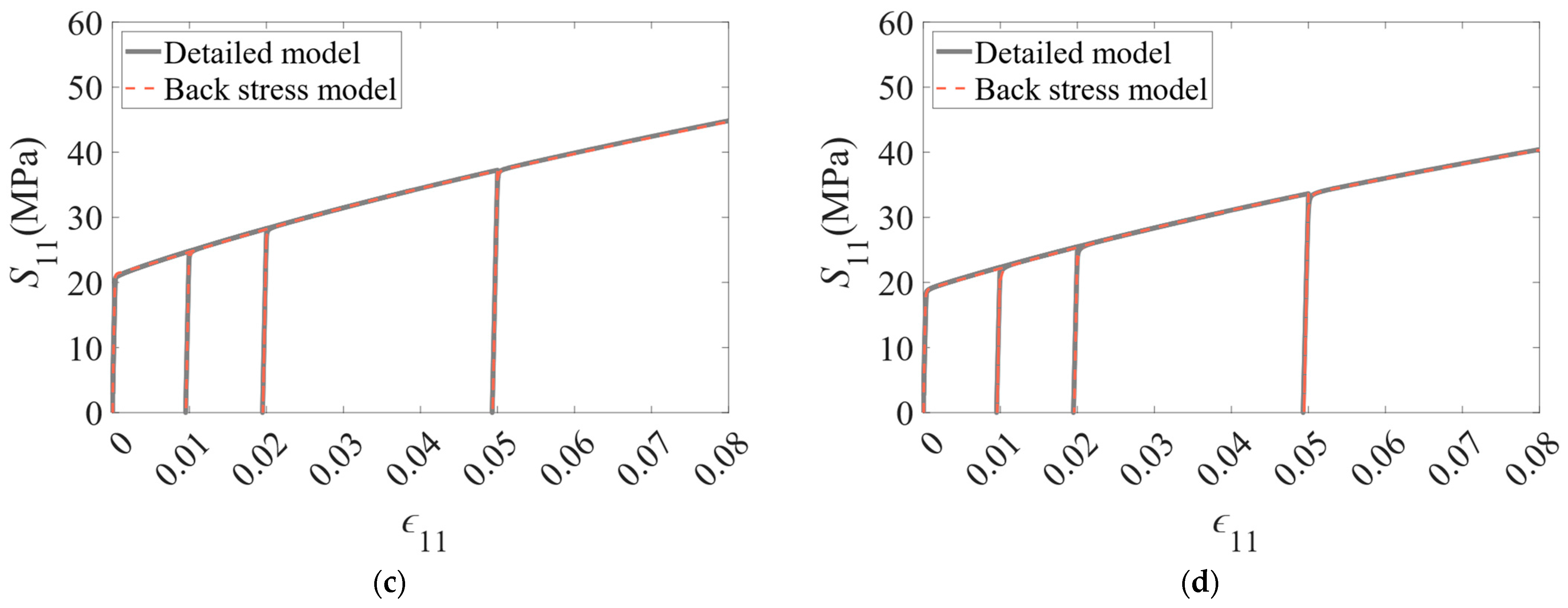
In Figure 2, the tensile–compression behaviour predictions with different pre-strains (1%, 2%, and 5%) of the full-field DAMASK simulations for the aluminium single cube crystal with a spherical, non-shearable particle, or voids of 5% and 10% volume fractions, are shown. It is seen that increasing the volume fraction of inclusions results in a more pronounced Bauschinger effect both for particles and voids; on the other hand, pre-strain has different effects, where an increasing pre-strain only enhances the Bauschinger effect for particles and not for voids. Also, it is observed that non-shearable particles have induced more back stress than voids.
Note that the crystal plasticity formulation for the representative periodic volume does not contain any specific length scale. Hence, the results are valid for any particle size with the given volume fraction.
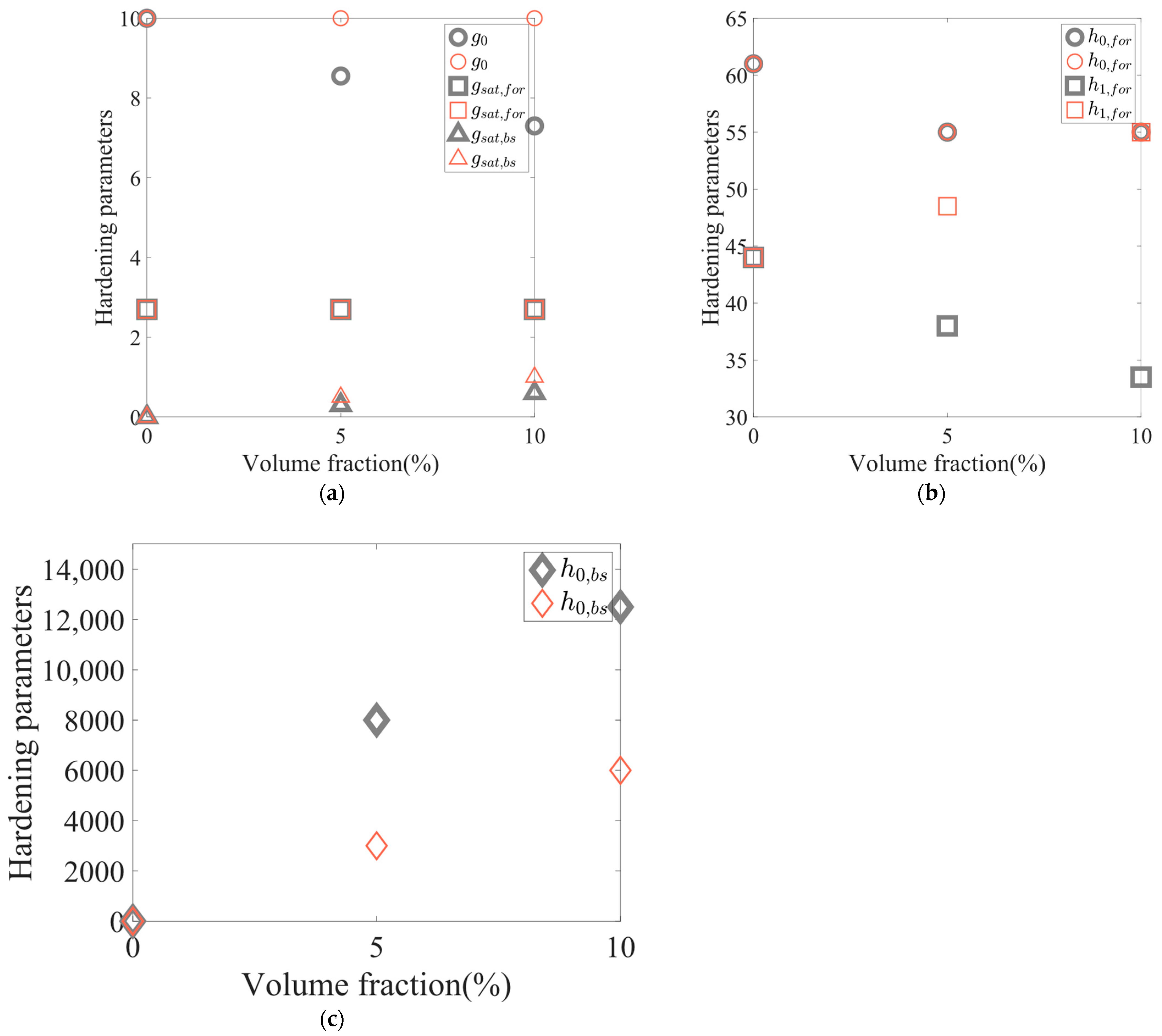
The parameters of the back stress model were calibrated to provide similar results to those of the detailed simulations of the detailed lower-scale simulations of the periodic array of particles. Figure 2 shows a comparison for stress–strain. The parameters were calibrated independently of the pre-strain but with different calibrations for the different volume fractions of particles/voids. The material parameters are listed in Table 1 and are also compared in Figure 3 for the different volume fractions.
In Figure 3a, it is seen that the saturation resistance ( g s a t , f o r ) can be chosen to be constant regardless of the type (particle/void) and volume fraction (0–10%) of the inclusion; however, in order to do that, one must adjust the asymptotic hardening rate   ( h 1 , f o r ) accordingly. The saturation resistance in reverse ( g s a t , b s )   increases linearly and slightly with the volume fraction of the inclusions. In Figure 3b, one can see that the asymptotic hardening rate   ( h 1 , f o r ) increases and decreases linearly with volume fraction for particle and void, respectively. Also, the reference hardening rate   ( h 0 , f o r ) is constant (55 MPa) for the void and particle with volume fractions of 5% and 10%. In Figure 3c, the reference back stress self-hardening ( h 0 , b s ) is increased with the volume fraction of the inclusions and it is also seen that ( h 0 , b s ) increases sharper for the void compared to the particle.
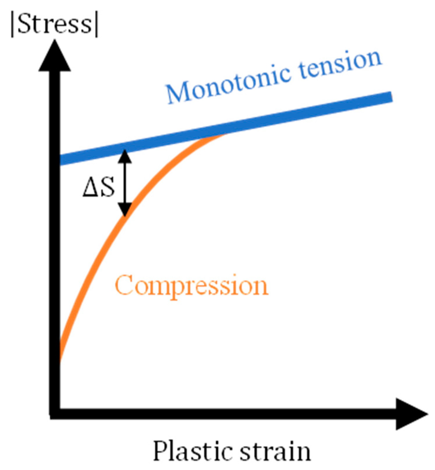
In Figure 4, a schematic illustration of a tension–compression stress–strain curve after pre-strain is given. In this figure, S shows the stress difference between monotonic tension and compression after pre-strain. This parameter is used to quantify the Bauschinger effect for the different cases considered, as detailed below.
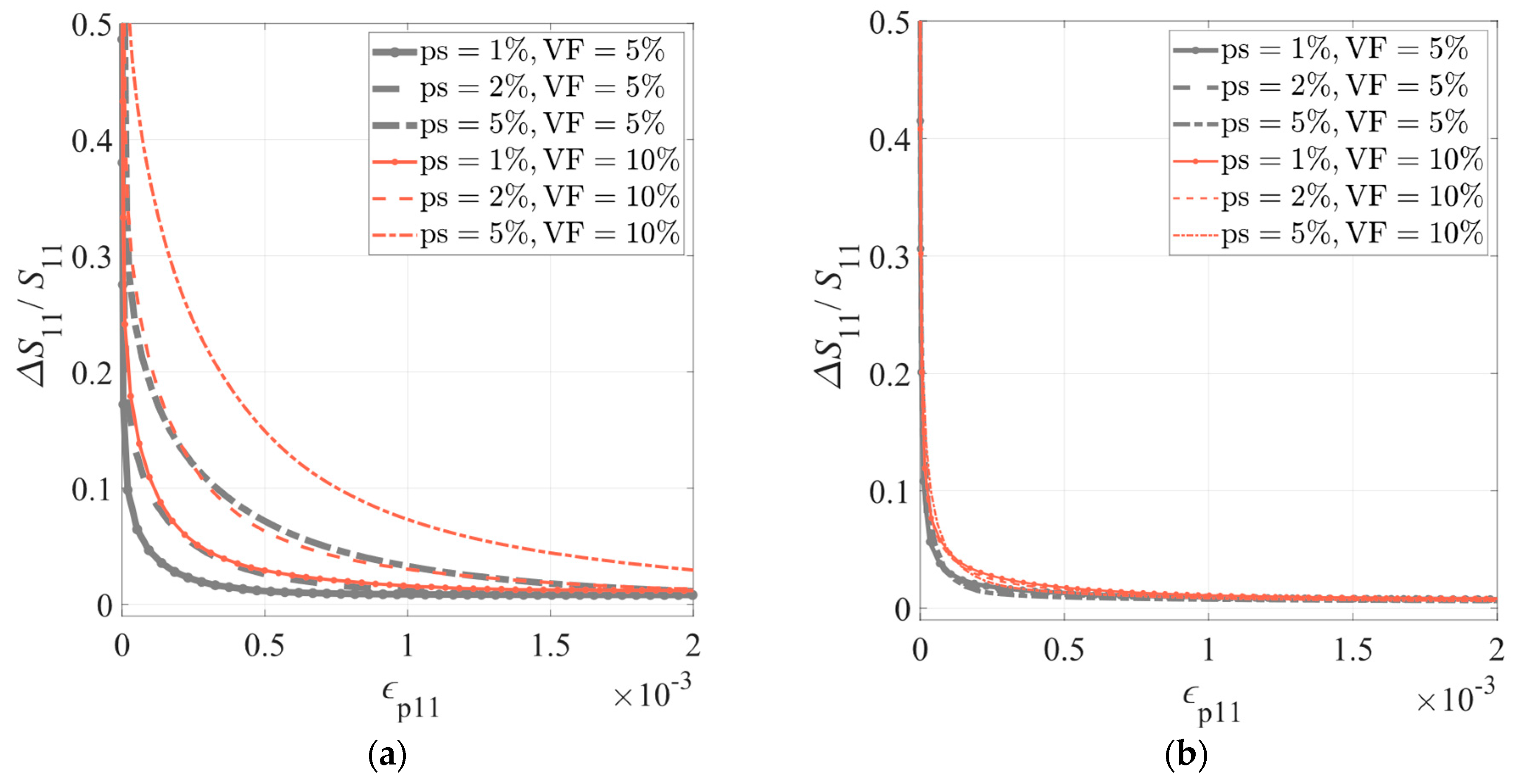
The calculated Bauschinger effect for an aluminium matrix including 5% and 10% of particle and void in terms of the normalised parameter S 11 / S 11 is shown in Figure 5. In this figure, S 11 and ϵ 11 represent the second Piola–Kirchhoff stress and the plastic strain in the monotonic tensile direction, respectively. It is seen that with particles (Figure 5a), the Bauschinger effect increases with the increase in volume fraction, and also with increased pre-strain. Also, for the void, (Figure 5b), the volume fraction has a direct correlation with the Bauschinger effect. However, the pre-strain does not affect the Bauschinger effect to any significant extent.

4. Discussion

In this paper, first, a two-phase material model was generated using the DREAM 3D software version 6.6.58. Then, the material properties of pure aluminium were given to the material matrix. Afterwards, the phenomenological plasticity model of the DAMASK software version 2.0.3. (in this paper referred to as the “detailed model”) was used to perform monotonic tension–compression tests on the models where the aluminium matrix contains inclusions (particle/void) of volume fractions of 0%, 5%, and 10%. These tension–compression tests were carried out in pre-strains of 1%, 2%, and 5%. Then, the back stress model with one phase was fitted to the results of applying the detailed model to simulate a crystal containing a periodic array of second-phase particles. Crystal plasticity models with and without back stress both exist in the DAMASK software version 2.0.3. The idea, here, is to tune the back stress model parameters in a way that this model can capture the Bauschinger effect introduced by second-phase particles at a lower length scale.
By simulating selected tension–compression tests of a crystal with particles or voids, the Bauschinger effect is analysed and compared. It is seen that the Bauschinger effect is observed more from particles, compared to from voids. Particles are modelled as inclusions with a very large yield strength and they remain elastic during the whole loading process. However, a plastic zone develops around the particles, relaxing the stress concentration. Voids are modelled as inclusions with very small elastic stiffness. The particles remain elastic during the deformation and store elastic energy during the tensile stage, which is released back to the system during the following compression. The elastic reversibility results in a temporarily weaker material. On the other hand, voids are modelled with a vanishing stiffness and cannot store elastic energy themselves. However, the plastic zone around them provides some strength contrast.
In Figure 2, it is shown that the back stress model can be fitted well to simulations of the crystal containing elastic particles or voids for the case of tension–compression tests in the [100] direction. This shows that, at least for this case, the Bauschinger effect caused by the second-phase particles or voids can be modelled at a larger length scale in a much more efficient way, considering the computational costs.
The back stress model has three parameters that control the back stress in the constitutive equations. One can call them the saturation back stress ( g s a t , b s ), the reference back stress hardening rate ( h 0 , b s ), and the asymptotic back stress hardening rate ( h 1 , b s ). The last one was set to zero in this study, since we were able to fit the curves simply by using the other two parameters. These two parameters ( g s a t , b s and h 0 , b s ) are used to model the “roundness” in the elastic–plastic transition after a strain reversal in the tension–compression curve.
In Figure 6a, it is seen that plasticity (plastic yielding) for the pure aluminium matrix and a matrix with a particle, begin at the same amount of stress, since it is the matrix that yields plastically in both systems. However, it is seen that the systems with voids yield earlier than the pure aluminium matrix. Also, the matrix, including a void volume fraction of 10%, has the weakest yield strength (lowest stress–strain curve) (Figure 6a). One can argue that both 5% and 10% volume fractions of void yield at the same time, since they have the same critical resolved shear stress, but the matrix with a higher volume fraction of void (in this case 10%) reaches the saturation stress later than the matrix with a 5% volume fraction of void (Figure 6b).
It was observed in Figure 5b that the pre-strain has a small influence on the Bauschinger effect caused by voids. This behaviour is similar to pure aluminium and one can discuss that the act of applying a pre-strain affects the hardening behaviour of the material by imposing a back stress; however, in this study, a void is modelled as an inclusion with an extremely small elasticity, which does not introduce a sensible back stress to the system and, because of that, increasing the pre-strain does not affect the Bauschinger effect for a matrix including a void. Also, it is observed in Figure 5 that the particle imposes an increased Bauschinger effect, which is because of the large elasticity that holds elastic energy in the particles that do not yield and, when performing compression, this acts in the opposite direction as long-range stresses.

5. Conclusions

The Bauschinger effects in an alloy containing second-phase particles or voids are studied. The procedure is, firstly, to perform detailed simulations of a periodic array of a volume fraction of particles or voids. Secondly, a constitutive model with a back stress incorporated to capture the Bauschinger effect is calibrated at a larger scale of a representative volume, for which the influence of the particles is homogenised, i.e., they are modelled by a kinematic hardening of the critical resolved slip systems of an equivalent one-phase material. Based on the results reported here, limited to a compression–tension test in the [100] direction, it was possible to do this with a good precision. The simulations show that the presence of second-phase particles generates a more rounded elastoplastic transition in reverse tests after pre-straining (Bauschinger effect in the small strains) than the presence of voids does. The level of the Bauschinger effect increases with the volume fraction of particles or voids. With particles, it also increases with an increased amount of pre-strain, while, with voids, it does not. An overview and a discussion of how the back stress parameters correlate with the amount of back stress is given.

Author Contributions

Conceptualization, A.I.A, B.H., T.M. and K.M.; methodology, A.I.A., T.M. and B.H.; software, A.I.A. and T.M.; validation, A.I.A., T.M. and B. H.; formal analysis, A.I.A., T.M. and B.H.; inves-tigation, A.I.A.; data curation, A.I.A. and B.H.; writing—original draft preparation, A.I.A.; writing—review and editing, A.I.A, B.H., T.M. and K.M.; visualization, A.I.A.; supervision, B.H., T.M. and K.M.; project administration, K.M.; funding acquisition, K.M. All authors have read and agreed to the published version of the manuscript.

Funding

A.I.A. acknowledges funding from the NTNU Digitalization Transformation initiative through the project ‘AllDesign’. T.M. acknowledges funding from the METPLAST project, supported by the Research Council of Norway, FRIPRO grant 315727. K.M. received funding from the Research Council of Norway through the Center for Research based Innovation SFI PhysMet, Grant. 309584.

Data Availability Statement

The original contributions presented in the study are included in the article, further inquiries can be directed to the corresponding author.

Acknowledgments

In this research, the computations were performed on resources provided by the NTNU IDUN/EPIC computing cluster [33]. We also thank Jan Christian Meyer from the Department of Computer Science, NTNU, for assistance with preparing DAMASK software 2.0.3 for the supercomputers.

Conflicts of Interest

The authors declare that the research was conducted in the absence of any commercial or financial relationships that could be construed as potential conflicts of interest.

References

  1. Hatano, T.; Matsui, H. Molecular dynamics investigation of dislocation pinning by a nanovoid in copper. Phys. Rev. B 2005, 72, 094105. [Google Scholar] [CrossRef]
  2. Santos-Güemes, R.; LLorca, J. Dislocation dynamics analysis of the strengthening induced by shearable and non-shearable precipitates in the presence of dislocation pile-ups. Eur. J. Mech.-A/Solids, 2023; in press. [Google Scholar]
  3. Ashby, M. The deformation of plastically non-homogeneous materials. Philos. Mag. A J. Theor. Exp. Appl. Phys. 1970, 21, 399–424. [Google Scholar] [CrossRef]
  4. Atkinson, J.D.; Brown, L.M.; Stobbs, W.M. Work-Hardening of Copper-Silica. 4. Bauschinger Effect and Plastic Relaxation. Philos. Mag. 1974, 30, 1247–1280. [Google Scholar] [CrossRef]
  5. Brown, L.; Clarke, D. Work hardening due to internal stresses in composite materials. Acta Metall. 1975, 23, 821–830. [Google Scholar] [CrossRef]
  6. Brown, L.M.; Stobbs, W.M. Work-Hardening of Copper-Silica. 2. Role of Plastic Relaxation. Philos. Mag. 1971, 23, 1201–1233. [Google Scholar] [CrossRef]
  7. Brown, L.M.; Stobbs, W.M. Work-Hardening of Copper-Silica. Philos. Mag. 1971, 23, 1185–1199. [Google Scholar] [CrossRef]
  8. Cahoreau, M.; Humphreys, F.J. The Rotation of Particles during the Deformation of a 2-Phase Copper Alloy. Acta Metall. 1984, 32, 1365–1370. [Google Scholar] [CrossRef]
  9. Hirsch, P.B.; Humphreys, F.J. Deformation of Single Crystals of Copper and Copper-Zinc Alloys Containing Alumina Particles. 1. Macroscopic Properties and Workhardening Theory. Proc. R. Soc. Lond. A 1970, 318, 45–72. [Google Scholar] [CrossRef]
  10. Humphreys, F.J.; Hirsch, P.B. Deformation of Single Crystals of Copper and Copper-Zinc Alloys Containing Alumina Particles. 2. Microstructure and Dislocation-Particle Interactions. Proc. R. Soc. Lond. A 1970, 318, 73–92. [Google Scholar] [CrossRef]
  11. Moan, G.; Embury, J. A study of the Bauschinger effect in Al-Cu alloys. Acta Metall. 1979, 27, 903–914. [Google Scholar] [CrossRef]
  12. Stobbs, W.M. Work-Hardening of Copper-Silica. 3. Diffusional Stress Relaxation. Philos. Mag. 1973, 27, 1073–1092. [Google Scholar] [CrossRef]
  13. Brown, L.M.; Stobbs, W.M. Work-Hardening of Copper-Silica. 5. Equilibrium Plastic Relaxation by Secondary Dislocations. Philos. Mag. 1976, 34, 351–372. [Google Scholar] [CrossRef]
  14. Bate, P. Modelling deformation microstructure with the crystal plasticity finite-element method. Philos. Trans. R. Soc. A 1999, 357, 1589–1601. [Google Scholar] [CrossRef]
  15. Gurtin, M.E. A finite-deformation, gradient theory of single-crystal plasticity with free energy dependent on the accumulation of geometrically necessary dislocations. Int. J. Plast. 2010, 26, 1073–1096. [Google Scholar] [CrossRef]
  16. Lee, W.M.; Zikry, M.A. Modeling the interfacial plastic strain incompatibilities associated with dispersed particles in high strength aluminum alloys. Acta Mater. 2012, 60, 1669–1679. [Google Scholar] [CrossRef]
  17. Fribourg, G.; Brechet, Y.; Deschamps, A.; Simar, A. Microstructure-based modelling of isotropic and kinematic strain hardening in a precipitation-hardened aluminium alloy. Acta Mater. 2011, 59, 3621–3635. [Google Scholar] [CrossRef]
  18. Okuyama, Y.; Tanaka, M.; Ohashi, T.; Morikawa, T. Modelling and Crystal Plasticity Analysis for the Mechanical Response of Alloys with Non-uniformly Distributed Secondary Particles. ISIJ Int. 2020, 60, 1819–1828. [Google Scholar] [CrossRef]
  19. Zhao, Q.L.; Holmedal, B. Modelling work hardening of aluminium alloys containing dispersoids. Philos. Mag. 2013, 93, 3142–3153. [Google Scholar] [CrossRef]
  20. Zhao, Q.L.; Holmedal, B. The effect of silicon on the strengthening and work hardening of aluminum at room temperature. Mater. Sci. Eng. A-Struct. Mater. Prop. Microstruct. Process. 2013, 563, 147–151. [Google Scholar] [CrossRef]
  21. Bate, P.; Roberts, W.T.; Wilson, D.V. The Plastic Anisotropy of 2-Phase Aluminum-Alloys. 2. Anisotropic Behavior in Load-Reversal Tests. Acta Metall. 1982, 30, 725–737. [Google Scholar] [CrossRef]
  22. Han, C.S.; Wagoner, R.H.; Barlat, F. On precipitate induced hardening in crystal plasticity: Theory. Int. J. Plast. 2004, 20, 477–494. [Google Scholar] [CrossRef]
  23. Han, C.S.; Wagoner, R.H.; Barlat, F. On precipitate induced hardening in crystal plasticity: Algorithms and simulations. Int. J. Plast. 2004, 20, 1441–1461. [Google Scholar] [CrossRef]
  24. Asgharzadeh, A.; Park, T.; Nazari Tiji, S.; Pourboghrat, F. A Computationally Efficient Multiscale, Multi-Phase Modeling Approach Based on CPFEM to Assess the Effect of Second Phase Particles on Mechanical Properties. Crystals 2023, 13, 1199. [Google Scholar] [CrossRef]
  25. Umar, M.; Qayyum, F.; Farooq, M.U.; Guk, S.; Kirschner, M.; Korpala, G.; Prahl, U. Exploring the Structure-Property Relationship in Spheroidized C45EC Steel Using Full Phase Crystal Plasticity Numerical Simulations. Steel Res. Int. 2022, 93, 2100452. [Google Scholar] [CrossRef]
  26. Qayyum, F.; Guk, S.; Kawalla, R.; Prahl, U. On Attempting to Create a Virtual Laboratory for Application-Oriented Microstructural Optimization of Multi-Phase Materials. Appl. Sci. 2021, 11, 1506. [Google Scholar] [CrossRef]
  27. Ali, M.; Qayyum, F.; Tseng, S.; Guk, S.; Overhagen, C.; Chao, C.K.; Prahl, U. Development of Hot Working Process Maps for Incompressible TRIP Steel and Zirconia Composites Using Crystal Plasticity-Based Numerical Simulations. Metals 2022, 12, 2174. [Google Scholar] [CrossRef]
  28. Sedighiani, K.; Shah, V.; Traka, K.; Diehl, M.; Roters, F.; Sietsma, J.; Raabe, D. Large-deformation crystal plasticity simulation of microstructure and microtexture evolution through adaptive remeshing. Int. J. Plast. 2021, 146, 103078. [Google Scholar] [CrossRef]
  29. Roters, F.; Diehl, M.; Shanthraj, P.; Eisenlohr, P.; Reuber, C.; Wong, S.L.; Maiti, T.; Ebrahimi, A.; Hochrainer, T.; Fabritius, H.-O. DAMASK–The Düsseldorf Advanced Material Simulation Kit for modeling multi-physics crystal plasticity, thermal, and damage phenomena from the single crystal up to the component scale. Comput. Mater. Sci. 2019, 158, 420–478. [Google Scholar] [CrossRef]
  30. Groeber, M.A.; Jackson, M.A. DREAM.3D: A Digital Representation Environment for the Analysis of Microstructure in 3D. Integr. Mater. Manuf. Innov. 2014, 3, 56–72. [Google Scholar] [CrossRef]
  31. Eisenlohr, P.; Diehl, M.; Lebensohn, R.A.; Roters, F. A spectral method solution to crystal elasto-viscoplasticity at finite strains. Int. J. Plast. 2013, 46, 37–53. [Google Scholar] [CrossRef]
  32. Wollmershauser, J.; Clausen, B.; Agnew, S. A slip system-based kinematic hardening model application to in situ neutron diffraction of cyclic deformation of austenitic stainless steel. Int. J. Fatigue 2012, 36, 181–193. [Google Scholar] [CrossRef]
  33. Själander, M.; Jahre, M.; Tufte, G.; Reissmann, N. EPIC: An energy-efficient, high-performance GPGPU computing research infrastructure. arXiv 2019, arXiv:1912.05848. [Google Scholar]
Figure 1. From left to right: A representative volume element (RVE) of size 1, containing a single spherical particle or a void with a radius r , with applied periodic boundary conditions, representing a regular grid of particles with a given volume fraction, contained within a single grain of a polycrystal. The RVE was discretized by 16 3 grid points.
Metals 14 00424 g001
Figure 2. The material parameters of the back stress model are calibrated to the detailed model simulation with an inclusion, for the case of a compression–tension test in the [100] direction. The inclusion is either particle (a,b) or void (c,d) with volume fractions of 5% (a,c) and 10% (b,d). Pre-strains of 1%, 2%, and 5% are considered. S 11 is the second Piola–Kirchhoff stress and ϵ 11 = F 11 1 is the nominal strain, where F 11 is the deformation gradient component. In this figure, the compression region is plotted on the positive stress axis to simplify comparison.
Metals 14 00424 g002aMetals 14 00424 g002b
Figure 3. Hardening parameters of the back stress model used for the calibrations in Figure 2, (a) g 0 ,   g s a t , f o r ,   g s a t , b s ; (b) h 0 , f o r , h 1 , f o r ; and (c) h 0 , b s . The orange colour corresponds to the particle and grey corresponds to the void.
Metals 14 00424 g003
Figure 4. A schematic illustration of a tension–compression stress–strain curve after pre-strain.
Metals 14 00424 g004
Figure 5. Normalised stress difference ( S 11 / S 11 ) between monotonic tension and compression with inclusions of (a) the particle and (b) the void for pre-strains of 1%, 2%, and 5%. “ps” stands for pre-strain. ∆S is shown in a schematic illustration in Figure 4.
Metals 14 00424 g005
Figure 6. (a) Stress (Cauchy)—strain (nominal strain) curves for pure aluminium matrix and aluminium matrix including particle/void. Here ϵ 11 = F 11 1 . (b) Cauchy stress, σ 11 with respect to plastic strain ( ϵ p 11 ) for pure Al matrix and matrix with 5% and 10% void inclusions.
Metals 14 00424 g006
Table 1. Hardening parameters of the back stress model, used for the calibrations in Figure 2. The values are in MPa and γ 0 = 0.001   s 1.
Aluminium MatrixVoidVoidParticleParticle
VF = 0%VF = 5%VF = 10%VF = 5%VF = 10%
g 0 108.557.31010
g s a t , f o r 2.72.72.72.72.7
g s a t , b s 00.30.60.51
h 0 , f o r 6155555555
h 1 , f o r 443833.548.555
h 0 , b s 0800012,50030006000
h 1 , b s 00000
Disclaimer/Publisher’s Note: The statements, opinions and data contained in all publications are solely those of the individual author(s) and contributor(s) and not of MDPI and/or the editor(s). MDPI and/or the editor(s) disclaim responsibility for any injury to people or property resulting from any ideas, methods, instructions or products referred to in the content.