Review

Untapped Opportunities in Additive Manufacturing with Metals: From New and Graded Materials to Post-Processing

by
Mohammad Hossein Mosallanejad
,
Reza Ghanavati
,
Amir Behjat
,
Mohammad Taghian
,
Abdollah Saboori
* and
Luca Iuliano
Integrated Additive Manufacturing Center, Department Management and Production Engineering, Politecnico di Torino, Corso duca Degli Abruzzi 24, 10129 Torino, Italy
*
Author to whom correspondence should be addressed.
Metals 2024, 14(4), 425; https://doi.org/10.3390/met14040425
Submission received: 19 February 2024 / Revised: 19 March 2024 / Accepted: 28 March 2024 / Published: 3 April 2024

Abstract

:
Metal additive manufacturing (AM) is an innovative manufacturing method with numerous metallurgical benefits, including fine and hierarchical microstructures and enhanced mechanical properties, thanks to the utilization of a local heat source and the rapid solidification nature of the process. High levels of productivity, together with the ability to produce complex geometries and large components, have added to the versatile applicability of metal AM with applications already implemented in various sectors such as medicine, transportation, and aerospace. To further enhance the potential benefits of AM in the context of small- to medium-scale bulk production, metallurgical complexities should be determined and investigated. Hence, this review paper focuses on three significant metallurgical aspects of metal AM processes: in situ alloying, functionally graded materials, and surface treatments for AM parts. The current text is expected to offer insights for future research works on metal AM to expand its potential applications in various advanced manufacturing sectors.

1. Introduction

Additive manufacturing (AM), known for its layer-by-layer production of components, emerges as a driving force in manufacturing processes, capturing the interest of both the industrial and academic sectors [1,2]. Metal AM holds numerous advantages and boasts a wide range of applications, revolutionizing traditional manufacturing processes [3,4,5]. One key advantage is the ability to produce complex geometric shapes with intricate designs that would be challenging or impossible through conventional methods. This not only enhances product performance but also allows for lightweight and optimized structures. Additionally, metal AM enables rapid prototyping, reducing the time and costs associated with traditional tooling [6,7]. Moreover, AM facilitates the customization of components, catering to specific needs and requirements. Industries such as aerospace, automotive, healthcare, and tooling benefit significantly from metal AM, utilizing it to produce lightweight aircraft components, customized medical implants, and high-performance automotive parts [8,9,10]. The ability to work with various metals, including titanium, aluminum, copper, and stainless steel, further expands the applications of metal AM across diverse sectors, contributing to its growing significance in modern manufacturing [11,12].
The AM of metals is often considered an innovative manufacturing method with numerous metallurgical benefits [8,13,14]. The process, characterized by rapid cooling rates and directional solidification, yields metallic components with unique microstructures and, under certain circumstances, three-dimensional, multiscale architectures [15,16]. Consequently, AM metal components can be featured with physical, mechanical, and metallurgical properties, meeting the stringent requirements of engineering applications [17]. Metallic AM is described as having the capabilities to revolutionize the time to market, the ecologicalimpact, and design considerations within the advanced manufacturing sector [18,19,20].
AM enhances metallurgical and mechanical properties and productivity compared to traditional methods [21,22]. On the other hand, the metallurgical advantages of AM extend to the production of large components in various metals, such as Ti, Al, and steel, utilizing techniques like Wire Arc Additive Manufacturing (WAAM) [8]. In addition to its benefits in large-scale manufacturing, AM’s intrinsic manufacturing flexibility enables the production of small batches of end-products following customers’ demands [23,24]. Regarding specific materials, AM has been a game-changer in the manufacturing of Ti alloys, altering the design and manufacturing landscape [1]. In terms of applicability, AM has been successfully applied to produce complex products with high precision, such as metal surgical guides, which serve as an affordable adjunct to oral and maxillofacial surgery [25], with dozens of other implemented applications reported for aerospace and automotive sectors [1,26].
Existing research has revealed the potential benefits of AM in the context of small- to medium-scale bulk production, and it is evident that the current understanding of AM metallurgical complexities is insufficient for further scale-ups. Although AM is widely acknowledged as a method capable of producing complex metal components, the available commercial alloys that can be processed via this method are limited (Section 2). The ability to implement gradient features, such as varying chemical compositions, is another important characteristic that should be explored to further expand the applicability of AM methods in various industries (Section 3). Given that this method allows for flexibility in terms of tolerance, geometrical complexity, chemical composition, and gradient features, it is crucial to ensure that the surface characteristics of the manufactured components are of appropriate quality to address key metallurgical considerations (Section 4). Consequently, this review paper, with its dedicated focus on three important metallurgical aspects, i.e., in situ alloying (Section 2), Functionally Graded Materials (FGM) (Section 3), and surface treatments of AM parts (Section 4), seeks to bridge this gap, not only contributing to the existing literature but also providing a valuable resource that enhances the understanding and applications of AM.

2. An Unprecedented Alloy Design Opportunity

Despite the numerous advantages considered for the AM method, such as the ability to produce parts with complex geometries and precise dimensions, as well as the possibility of processing refractory metals due to the use of a concentrated heat source, this novel technique has only been extensively used with a few commercial alloys. Consequently, developing AM methods to produce alloyed components out of elementally blended mixtures, rather than merely pre-alloyed powders, saves money. It offers careful compositional tailoring, opening up enormous possibilities to make non-conventional alloy compositions functionally gradient chemical compositions and properties [27,28,29,30]. Also, the distinctive thermal and processing features of AM enable the fabrication of novel alloys with microstructures and characteristics that would be unattainable otherwise. Consequently, besides the conventional alloys successfully utilized to produce dense components, more new alloys have lately been developed, especially for AM processes [29,30,31].
Preparing the feedstock powder is the first stage in powder-based AM production processes. Pre-alloyed powder or an elemental mix of the component particles can be used as the raw material for powder-based AM techniques [27,32]. The powder mixing method for obtaining new alloy compositions for AM works is successful if the chemistry of the product is a close match to the new composition being investigated. Accurate control over the printed sample composition is crucial for a successful in situ alloying process. This critical aspect of the alloy design primarily depends on the feedstock selection and preparation method, the chemical mixing of the powders in the melt pool during printing, and ensuring chemical uniformity in the resulting product. Although some authors have reported instances of superior chemical mixing and reasonably uniform chemical dispersion in the printed part, there are numerous cases in which significant chemical heterogeneity remains after printing.
Moreover, the solidification-related elements, such as the enthalpy of mixing, the Marangoni force (Figure 1), a fluid flow stemming from the surface tension gradient due to the thermal field in the melt pool, and the Columnar–Equiaxed Transition (CET) occurrence (Section 2.1), are also significant aspects for any alloy design step in AM works [27]. Temperature-induced changes in surface tension determine the direction of the Marangoni flow in the melt pool. Depending on the properties of the melt, this flow can either be clockwise or counterclockwise, leading to alterations in the geometry of the melt pool (Figure 1a). Consequently, the resulting texture formed during solidification is also impacted (Figure 1b). The role of alloying elements in modifying the solidification range and inducing CET is schematically shown in Figure 2. This feature has been utilized in numerous AM alloy design works [27], some of which are summarized in this chapter.
The powder size and characteristics should be selected according to the qualities of the alloying elements to produce a dense and homogeneous product. Moreover, the impact of the thermophysical characteristics and the composition effects of the powder blend, in addition to the basic criteria for selecting AM powders, should be taken into account [36]. It is challenging to alter the conditions favoring the equiaxed development of titanium grains by relying solely on AM processing parameters. Instead, numerous works have attempted to change the chemical composition to attain the desired microstructures [27,37]. However, while some alloy strategies are centered on the formation of a solute layer ahead of the solidification front [30,31], others focus on the formation of secondary phases for grain refinement [38].
The development of novel alloys via AM has attracted the interest of numerous researchers, and as a result, a number of reviews have been published in this area. Mosallanejad et al. [27] and Sing et al. [37] separately conducted comprehensive reviews on the use of elemental powder for producing alloys via laser-based AM methods and outlined a framework for alloy design via AM methods, while Clare et al. [39] systematically reviewed the design aspects by discussing the role of thermodynamics, solidification, and AM methods in controlling the characteristic microstructure and property during AM. This section explores some of the AM studies on alloy design, which may include utilizing either elemental powders, pre-alloyed powders, or both as feedstock, and it illustrates the phenomena that occur during in situ AM alloying.

2.1. Pure Elements

The use of pure element powder to produce the necessary alloys in the industry sector is the most basic step that can be taken in the process of designing and developing new alloys using AM. According to the findings of previous researchers, this approach is associated with challenges like differences in the thermophysical properties of the applied components and the heterogeneity of the result [27]. However, it can significantly expand and improve the prospect of alloy design in AM processes. A wide range of alloys has been dedicated to employing a mixture of pure elements to develop desired alloys using AM. Ti alloys, Al alloys, High-Entropy Alloys (HEAs), and Mn-, Mg-, and W-based alloys are examples of these metals [27,40,41].
However, researchers usually take different factors into consideration when developing alloys for AM methods. The high-temperature gradient in the melt pool of AM processes produces strongly textured microstructures that are inappropriate for several applications. The intense texture can be alleviated by preheating the substrate; however, this is not possible in most cases. Another option to counteract the thermal gradient’s impact is to change the solidification mode by introducing alloying elements that function as nucleants or CET promoters. In earlier AM works, the growth restriction factor (Q) was used to assess an element’s effectiveness as a grain refiner by triggering the potent nuclei ahead of the solidification front. More specifically, it denotes the contribution of a solute element to the diffusion boundary layer development rate in constitutional undercooling situations. The measure was first proposed by Maxwell and Hellawel as follows [42]:
Q = m·C0·(k − 1)
where C0 is the solute concentration in the alloy melt, and m and k are the liquidus slope and equilibrium solute distribution coefficient in the associated phase diagram. It is widely accepted that solute rejection from the solidification front into liquid delays recalescence, offering more time for nucleation to proceed. Mendoza et al. [43] added W to pure Ti to induce grain refinement during the Directed Energy Deposition (DED) process (Figure 3). Compared to other widely used alloying elements in Ti, W has a high growth restriction factor (Q) of 22.65 C0. The authors believe grain refinement can be described in two scenarios: “solute-based” and “nuclei-based” mechanisms.
Employing the same solidification effect, Mantri et al. [44] altered the columnar texture of AM β-Ti alloys by adding trace amounts of boron. According to the results, the morphology of α precipitates from lath-like to more equiaxed when boron was added to a Ti-12 wt.% Mo alloy (Figure 4).
Furthermore, the addition of 0.5 wt.% boron reduced the Ti-20 wt.% V and Ti-12 wt.% Mo particle sizes from almost 2 mm to 35–40 and 10–20 µm, respectively (Figure 5). According to the authors, TiB precipitates serve as α precipitates’ formation sites, and the refinement of prior β grains is brought on via constitutional supercooling created due to boron rejection into the liquid [44].
Creation of a large amount of Q when added to Ti, Cu is also a viable candidate for designing Ti-based alloys by the AM process. Hence, Ti–Cu alloys have been investigated using Laser Powder Bed Fusion (LPBF) [45,46] and DED [29] methods. As outlined in Equation (1), copper with a maximum solubility of 17 wt.% in β-phase titanium can create a Q as high as 110.5 when added to Ti, given the fact that m · (k − 1) = 6.5 K for this alloy [29]. Zhang et al. [29] adopted the mentioned idea to produce Ti–Cu alloys with a high yield strength and uniform elongation using the DED method. The utilized laser power and scan rate were 800 W and 800 mm/min, respectively. Ti–Cu alloys with ultrafine fully equiaxed prior-β grains and α/Ti2Cu eutectoid lamellar microstructure were achieved. Consequently, the highest yield strength (1023 ± 29 MPa) and Ultimate Tensile Strength (UTS) (1180 ± 21 MPa) were measured for the Ti-8.5 wt.% Cu alloy, with the elongation being 2.1 ± 0.6%, which are comparable to those of the cast and wrought Ti-6Al-4V alloy. Mosallanejad et al. [46] investigated the production of a Ti–Cu alloy via the LPBF method. The Rosenthal method was used to simulate the melt pool formation on Ti and Cu surfaces, which suggested that Cu particles, with a melting point lower than Ti, could not be fully melted using the laser beam even at the highest volumetric energy density. These particles would dissolve in the more easily created Ti melt pool. The above findings mark the importance of considering the constituents’ thermophysical properties.

2.2. Pure Elements Added to Pre-Alloyed Powders

Some alloy design strategies rely on forming secondary phases for microstructure modification, rather than rejecting solutes into the liquid. The varying solidification rate throughout the solidification process is usually a key point when in situ intermetallics are employed as nucleation sites. Xu et al. [38] produced Al–Fe–Cu–xZr alloys (x = 0.6, 0.8, and 1.3 at %) via the LPBF method. The feedstock was prepared via the induction of the melting of the associated ingots, followed by atomizing to prepare the powders. EBSD results are shown in Figure 6, where it can be noticed that the majority of the grains in both fine grain zones (FGZs) and coarse grain zones (CGZs) are equiaxed, except for the Al–Fe–Cu–0.6Zr alloy in CGZs, which exhibits a minor columnar characteristic. It can also be noted that the grain size in CGZs and FGZs decreased as the Zr concentration increased.
Perhaps the main point is that Al3Zr precipitates that developed close to the melt pool border served as Al grain nucleation sites, resulting in FGZs. On the other hand, the Al3Zr precipitation was suppressed as the solidification rate increased with the development of the solidification front, resulting in the formation of CGZs inside the melt pool [38]. The true stress–strain curves of the three Al alloys produced by Xu et al. [38] under uniaxial tension are illustrated in Figure 7. The yield strength (σy) increased with Zr content. CGZs and FGZs decreased with increasing Zr content (Figure 6), a behavior that explains the trend observed in Figure 7.
The selection of a technology that meets the required alloy design constitutes an important factor affecting the alloy properties produced through the AM process. Different AM techniques share characteristics such as rapid solidification and a significant temperature gradient in the melt pool. Due to the intense temperature gradient, a fast cooling rate alone cannot usually result in the fine graining of the finished product.
In powder-based AM processes, regardless of whether the heat source is electron or laser, a higher heat input under constant spot scan rate conditions increases the temperature and size of the melt pool. On the other hand, since the AM process is performed layer by layer, hotter molten pool transfers more heat to the previous layers, thereby increasing the substrate temperature and the melt pool depth. The overall effect would be the alleviation of the thermal gradient. Employing the electron beam, as opposed to the laser beam, similarly decreases the melt pool thermal gradient, thanks to the higher energy of the electron beam. Figure 8 compares the thermal gradient associated with the Electron Beam Melting (EBM) method with other powder-based AM processes. Similarly, Mosallanejad et al. [31] used the EBM method to induce CET in the Ti–6Al–4V alloy by adding 7 wt.% Cu to the initial powder mixture. Figure 8 shows that a higher constitutional undercooling (ΔTc > ΔTc’) further promotes the CET at a lower thermal gradient.
The microstructural changes after adding Cu to the Ti–6Al–4V alloy powder are depicted in Figure 9, where it can be observed that the columnar grains were successfully converted to equiaxed grains after Cu was added. Another prominent finding reported by the authors was the enhanced chemical homogeneity noticed in the designed alloy compared with the past works on the in situ production of Ti–Cu alloys via AM, where local Cu-rich zones were reported [46,47,48], citing density and viscosity differences between Ti and Cu in the liquid state. Also, Mosallanejad et al. [46] suggested that the Cu particles could not be fully molten using the laser beam due to their poor absorption coefficient of copper for the laser beam. Therefore, utilizing an electron beam leads to proper energy absorption by copper particles. The homogeneity of the chemical composition can also be due to the high input heat, resulting in the formation of a large molten pool. The Marangoni process during the solidification and re-melting of the previous layers due to the melting of the new layers and can be considered the other influential factor.
It should be noted that adding an element to a commercial alloy is sometimes carried out for other purposes, such as preventing the formation of defects. Identifying the processes underlying defect formation, including the primary variables that impact them and their propensity to occur, helps shed light on them. For instance, many alloys, even those with excellent weldabilities like Hastelloy X and Haynes 230, are unable to withstand the rapid cooling rate and regionally varying temperature gradients experienced during the laser AM process. As a result, they ultimately show significant cracking under thermal stress, the most common kind of which is hot cracking, also referred to as solidification cracking in casting. It typically occurs during the final stage of liquid pool solidification. For instance, using segregation engineering, Zhao et al. [49] successfully eliminated hot cracking in Haynes 230 super alloys during the laser AM process by introducing a continuous, uniform interdendritic liquid layer in the final stage of solidification. In essence, this method used low partition coefficients of Zr to create a stable liquid layer that is continuous at the grain and cell borders, allowing for liquid backfilling to reduce stress concentration. Zr atoms can delay dislocation climbing and reinforce the bonding at grain boundaries by reducing elemental diffusion rates at grain boundaries and filling vacancies.

2.3. Mixture of Pre-Alloyed Powders

Modifying a commercial alloy using another commercial alloy is one of the appealing yet practical ideas for developing new alloys using the AM method. This approach offers the benefit that, under certain circumstances, raw materials might be available, in which case there would be no need to supply new materials to develop novel compositions with distinctive properties. Although the interaction between the base elements in both alloys is crucial when using this technique, it is also essential to consider the potential of interfering intermetallic compounds forming. However, intermetallics have also been employed in the literature to enhance the alloy’s properties via AM [50]. Li et al. [51] added a B4C compound to Ti–6Al–4V to benefit the in situ formation of TiB and TiC intermetallics, weakening the texture intensity of α-Ti by increasing the varieties of α variants. Adding B4C to Ti–6Al–4V was also suggested to cause grain refinement for the β grains, thanks to the constitutional undercooling created due to the rejection of C and B ahead of the prior β grain solidification front, as shown in Figure 10.
Zhang et al. [30] offered the modulation of the microstructure in a Ti alloy by employing a mixture of Ti–6Al–4V powders modified by 316L stainless steel powders. The authors demonstrated that producing micrometer-scale concentration modulations containing the main elements found in 316L in the Ti–6Al–4V matrix was feasible through the partial homogenization of the two dissimilar alloy melts. Consequently, a β + α′ dual-phase microstructure (Figure 11a) with a progressive transformation-induced plasticity (TRIP) effect resulted, creating a high tensile strength of 1.3 GPa, a uniform elongation of about 9%, and an excellent work-hardening capacity of more than 300 MPa (Figure 11b). It can be observed that strength and ductility were simultaneously achieved upon adding 4.5 wt.% 316L stainless steel powders to Ti–6Al–4V feedstock. According to the authors, in this composition, the 60% vol. of the resultant microstructure consists of the β phase, which has a higher level of work hardening, and the stress-induced β to α′ martensitic transformation (SIMT) is triggered at higher stress. The creation of CET by adding Fe to liquid Ti is another influential factor leading to the enhancement of mechanical properties.

3. Functionally Graded Materials

3.1. Definition, Classification, and Applications

Functionally graded/gradient materials (FGMs) are defined as materials with the gradual evolution of chemical composition or structural features at different scales across preferred directions to provide site-specific properties without abrupt changes [52,53,54,55]. This concept was derived from simple examples in nature (imagine a wood or bone cross section) that have placed FGMs in the latest stage of continuous material development shown in Figure 12. In other words, it was inevitable to combine different materials due to the wide range of service needs in today’s advanced applications. However, the main weakness of typical multi-material structures (mainly joints or composites) is sharp interfaces, which cause premature or even catastrophic failure. As a result, FGMs have been suggested to increase the efficiency and lifespan of engineering structures by minimizing or eliminating abrupt changes. Different types of FGMs can be classified based on size into thin (coatings) and bulk and based on the structure as continuous or discontinuous. Figure 13 schematically illustrates continuous and discontinuous FGMs with structures for each type. It can be noticed that, in discontinuous FGMs (Figure 13a), the changes are step-wise, and the interface can be recognized along the structures (Figure 13c–e). Meanwhile, in continuous FGMs (Figure 13), the changes along the position are integral, and it is practically impossible to recognize the interface throughout them (Figure 13) [52].
The FGMs were first proposed for thermal barriers [58] and are now widely employed as advanced materials in high-performance multi-functional or critical conditions in high-tech industries such as energy [59], aerospace [60], and medicine [61]. Figure 14 presents the diversity of the application areas of FGMs with examples for each. Also, Figure 15 shows FGM prototypes for the rocket nozzle, automotive valve stem, and space mirror from the design to the final part. A research work aimed at demonstrating the superiority of FGMs compared two 304L stainless steel-Inconel 625 valve stem parts, one produced via the FGM method and the other friction-welded, using FEM method. The results showed that, at the operating temperature of 1000 K, there was a nearly 10-fold reduction of stress concentration in the gradient valve stem compared to the latter [62].

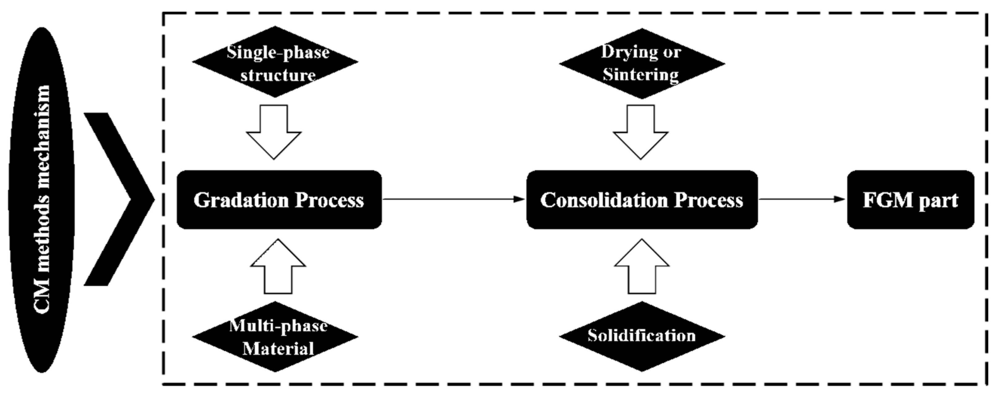
3.2. Manufacturing Methods: Conventional vs. AM

The selection of a manufacturing method is an important step in producing an FGM part because the realization of the complex and detailed design of FGMs (in terms of their chemical composition, microstructure, and geometrical features) is highly dependent on the manufacturing method. In addition, the production process should be economically viable while considering the environmental aspects. Table 1 shows the categorization of conventional manufacturing (CM) methods based on the initial material state and size of FGMs. In general, the mechanism of CM methods for producing an FGM part includes two separate stages of gradation and consolidation processes, as shown in Figure 16. The gradation operation is typically carried out by progressively adding a multi-phase material to a single-phase structure, following a preliminary design, using chemical, physical, and mechanical procedures or a combination of them. Then, the final FGM part is often achieved through a consolidation process such as solidification and drying or sintering. Although each of the CM methods has its own advantages, the multi-stage production, along with some inherent disadvantages such as limitations in terms of geometry (e.g., in centrifugal casting) and density (e.g., in powder metallurgy), high energy consumption, and environmental damage (e.g., in CVD/PVD or SHS), are considered obstacles to the further spread of FGMs via CM methods [11,63].
Nevertheless, the emergence of AM technology with the unique features mentioned at the beginning of this paper has opened a new window for the development of FGMs [65]. The layer-wise nature of AM allows for more precise control over the gradient and geometrical characteristics when producing FGMs with more complex designs. In addition, integrating the two stages of gradation and consolidation processes and reducing materials waste makes AM more economical and environmentally friendly than CM. As shown in Figure 17, AM processes, including stereolithography, material jetting, fused deposition modeling, and melting- and solidification-based processes, can fabricate FGMs. However, the processes mainly based on melting and solidification, i.e., DED and PBF, are used to produce metallic FGMs. In this regard, DED is more popular due to its powder-blowing or wire-injection mechanism and, thus, high flexibility in adjusting and altering the chemical composition during the process [66].
Figure 18 shows a laser-directed energy deposition (L-DED) process able to continuously control the chemical composition along the build direction to fabricate an FGM part [67]. In contrast, the difficulty of successively changing the composition of the powder bed in the PBF system has made it less likely to be used for the fabrication of compositionally graded materials, though PBF is leading the production of structural gradients (e.g., graded lattice). However, the advantages of PBF over DED, including the superior resolution, high surface quality, minimal requirement for post-processing, and easy control over feeding the designed composition (especially in cases with highly different densities of base materials such as metal–ceramic gradient structures), have led to some efforts in recent years to adapt the PBF process for the fabrication of compositional FGMs [68,69].
Figure 19 schematically shows some developed mechanisms for material spreading in the PBF process adapted for compositional FGMs. The blade-based dual-powder recoater (Figure 19a) was first developed by researchers in Singapore to fabricate copper-stainless steel bimetal. Therefore, this method is only suitable for the AM of bimetallic structures, though later solutions were made to upgrade it to a system that can simultaneously spread dissimilar materials in the same layer. The ultrasonic-based dual powder dispenser (Figure 19b) uses ultrasonic waves to selectively dispense the powders with a uniform rate and micro-scale precision. However, the very low production rate and non-uniformity of the layer thickness are among the method’s challenges.
In an electrophotographic-based dual powders dispenser (Figure 19c), the powder particles are accurately placed on a cylindrical mesh via a micro-airflow, and the deposition process is carried out using a (laser) heat source by blowing them off the mesh onto the platform. The last mechanism in Figure 19d combines the blade-based and ultrasonic-based mechanisms for spreading main constituting and secondary powders, respectively, with a micro-vacuum for suctioning excess unmelted powders in each layer. This method, developed at the University of Manchester, in addition to the point-by-point precision provided via the ultrasonic-based mechanism, has a much higher production rate. It has been demonstrated that the method can employ up to seven materials simultaneously [69].

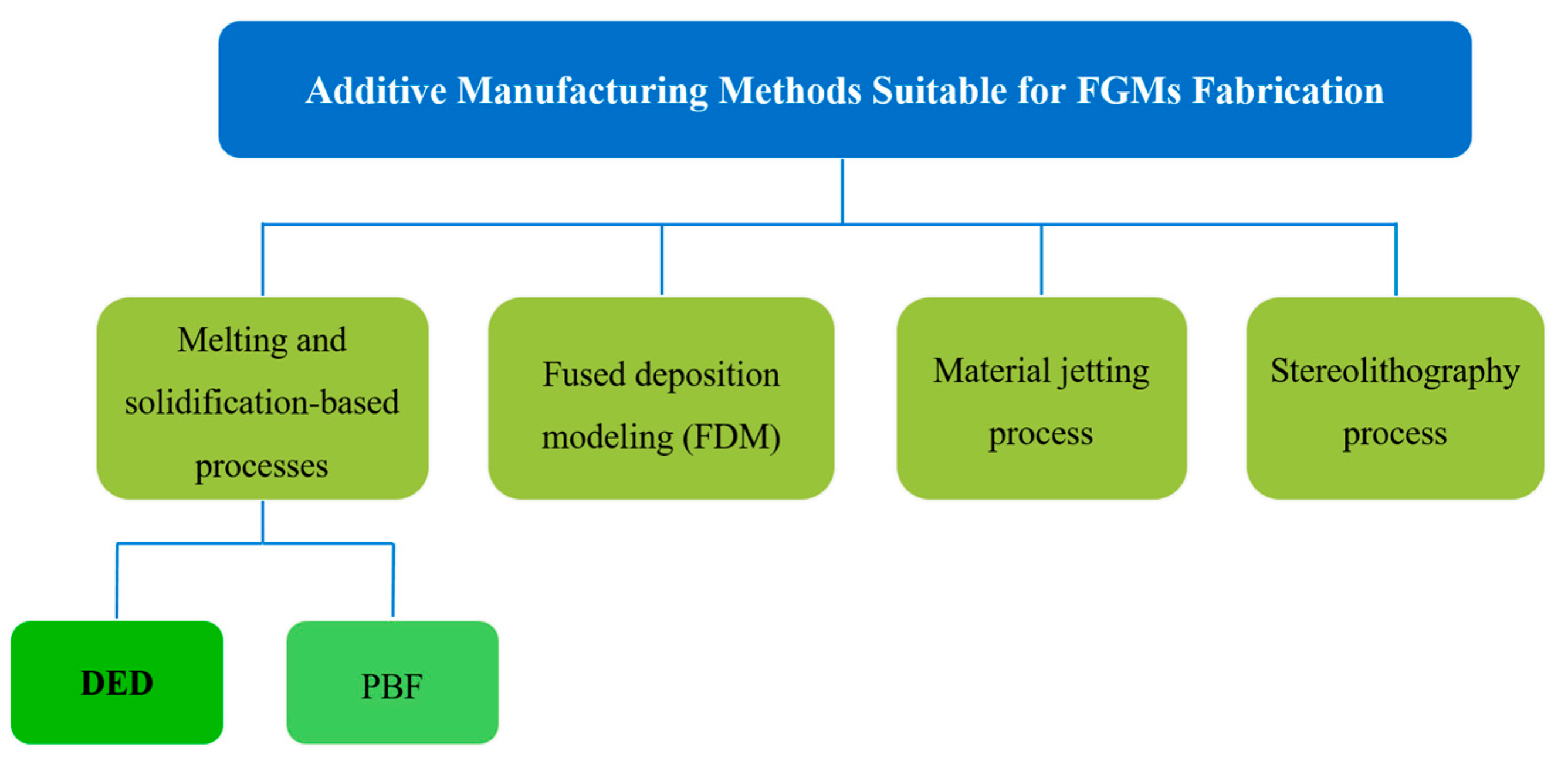
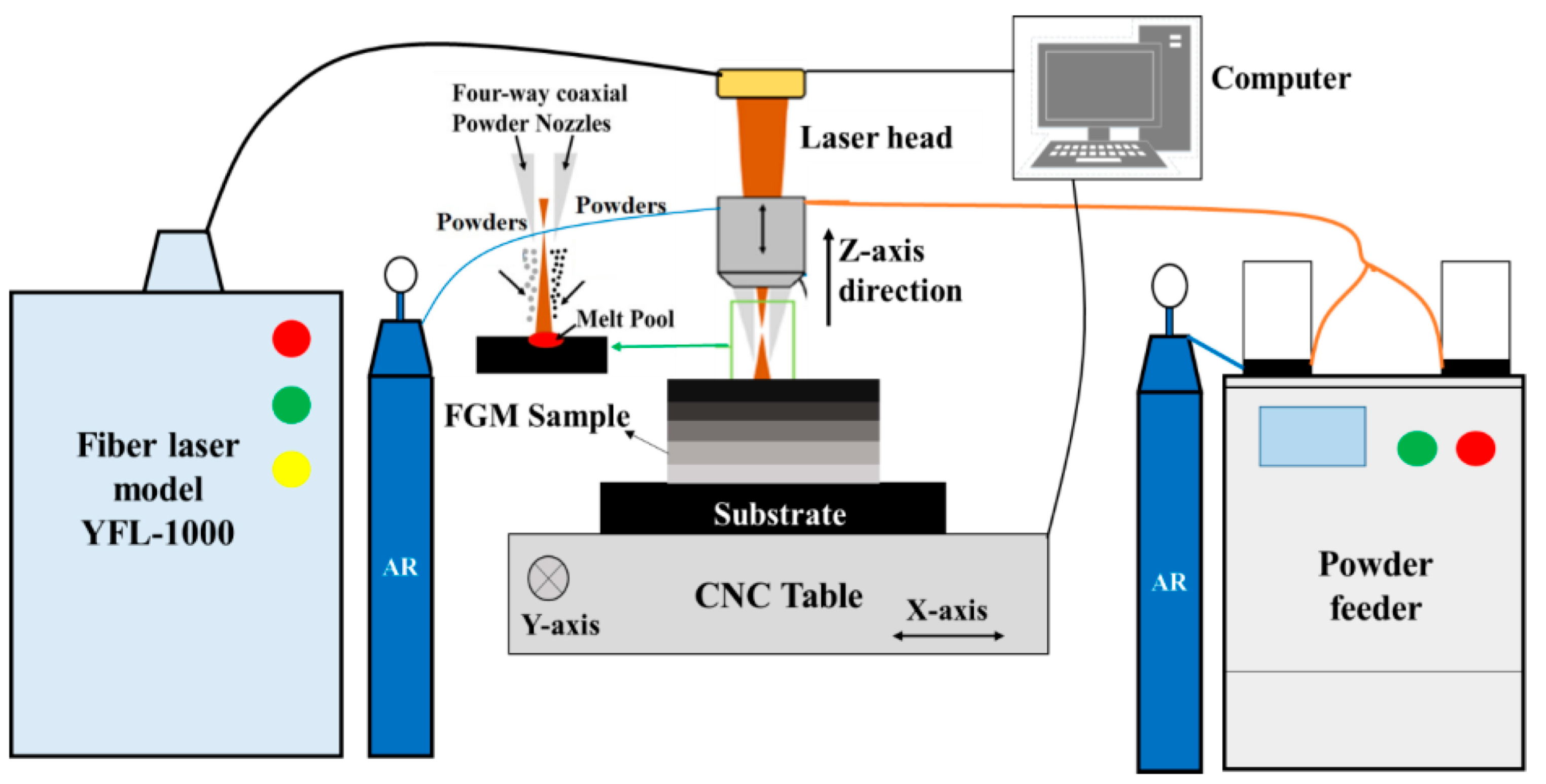
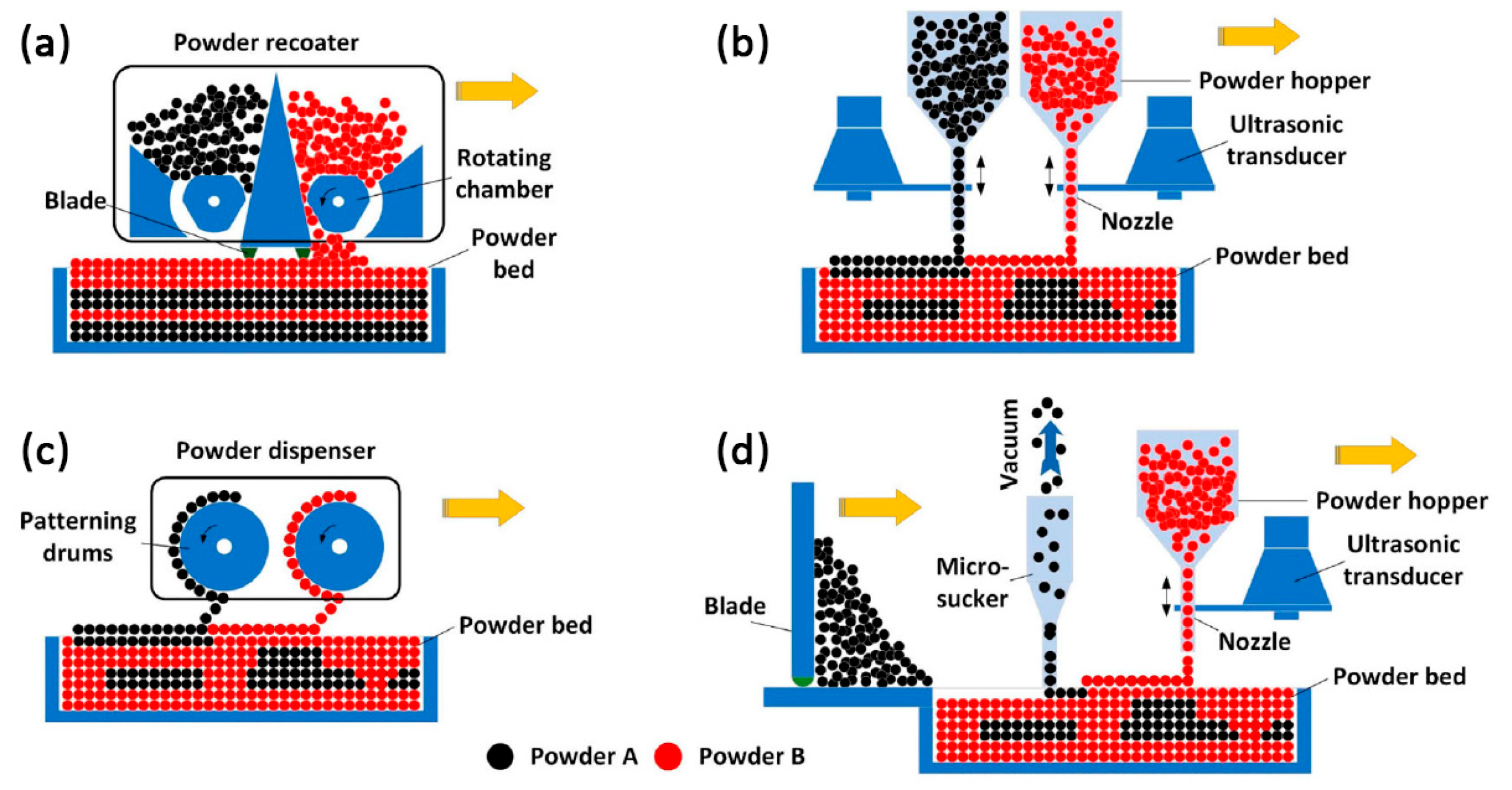
3.3. AM Framework for FGM Structures

Extensive studies on the AM of FGMs over recent years have led to the transition from the research and development stage to standardization, like ISO/ASTM TR 52912 [70], developed to ensure the final quality. Figure 20 shows a practical outline for the development of metallic FGMs via AM. The selection of base materials in the first step necessitates a thorough comprehension of the service requirements and their metallurgical compatibility. For instance, the service conditions of land-based or aero-gas turbine components are entirely different in hot and cold sections. The durability of microstructure and mechanical properties at high temperatures and highly corrosive environments often dictates the application of nickel-based superalloys and refractory metals in the hot section (e.g., combustion chamber). When considering weight and cost savings in the cold section, titanium-based alloys and steels are preferred for their respective properties. To achieve the requirements mentioned above in a gas turbine, the usage of dissimilar structures of Ni-based superalloy, Fe-based alloy, and Ti-based alloy is inevitable. However, each pair encounters unique metallurgical compatibility issues that must be considered when building the gradient structure in the following step. Due to their distinct natures, connecting Ti- and Fe-based alloys suffers from severe incompatibility. As a result, manufacturing a dissimilar structure out of them is highly prone to failure, even in graded form. Hence, special measures are necessary for the design step, which will be discussed further. Table 2 summarizes the compatibility of different base alloys comparatively from three aspects of “intermetallic formation and solubility limitations,” the “mismatch of thermal property,” and “other metallurgical effects,” based on the literature [71,72,73].
Figure 21 illustrates some compositional gradient designs proposed in AM. Figure 21a–f is related to the gradation of alloys and metal matrix composites (MMC), respectively. Regardless of the FGM types, the gradient design necessitates understanding the physical metallurgy of constituent element interaction. It can be seen from Figure 22 that, although the intermediate element of vanadium (V) was used in the Ti6Al4V to 304L stainless steel gradient structure (as the design in Figure 21d), multiple cracking caused due to the formation of brittle intermetallic Fe–Ti (crack #1) and σ-FeV (crack #2) prevented its successful fabrication [74].
Figure 23 explains how the Calculation of Phase Diagram (CALPHAD) method can be employed as a helpful guide for the gradient design on a ternary phase diagram of X–Y–Z. When assuming the γ phase is detrimental, the linear gradient path (red) between terminal alloys 1 and 2 contains a large amount of γ phase. Instead, binary (yellow) and arbitrary (green) gradient paths avoid the formation of an undesirable γ phase in the structure. Realizing the arbitrary gradient path is operationally more challenging than the binary because the AM system must be able to use more than two materials simultaneously (for example, the DED system must be equipped with more than two separate powder feeders) [75]. Figure 24 represents equilibrium and Scheil–Gulliver ternary phase diagrams of Cr–Fe–Ti and Fe–Ni–Ti systems calculated using the powerful Thermo-Calc software. It can be shown that their linear gradient path (the white dashed line) from Ti to stainless steel contains various detrimental (brittle) phases, leading to the failure of the designed composition. The difference in predicting phase composition regions between the equilibrium and Scheil–Gulliver diagrams is due to the slow kinetics of secondary phase formation under non-equilibrium solidification conditions (as in AM) and neglecting the solid-state transformation in the latter. However, their overlap creates feasibility diagrams whose combination for the Ni–V–Ti–Cr–Fe system (Figure 25) elucidates the feasible areas, without the risk of deleterious phase formation and cracking, for the gradient design between terminal alloys [76].
It should be highlighted that, in order to apply any gradient design, the AM process must first support the necessary capabilities; for example, the DED and PBF systems must be equipped with separate powder feeders and powder-spreading mechanisms to deliver the materials according to the gradient design. Second, the various features of each gradient step necessitate the adoption of specific optimal processing parameters to prevent defects (e.g., porosity, residual stress, etc.). For this purpose, applying online feedback systems, numerical modeling, and machine learning approaches might be helpful. Finally, like other production processes, quality control of the final part is required to ensure the intended performance under physically simulated service conditions, esp. corrosive environments, as well as dynamic and multi-axial loading, to which less attention has been paid in the literature and often focused on the FGMs design and fabrication.

4. Post-Surface Treatment; Creation of Novel Opportunities

Despite several advantages of AM, certain challenges, some depicted in Figure 26, should be addressed before the technology is widely adopted and commercialized [77,78,79].
According to the literature, the quality challenges of AM metallic products are porosity, poor surface finish, and tensile residual stresses. These issues mostly appear in the post-print stage after the geometry is generated [80] and negatively affect the mechanical properties, especially the fatigue performance of AM metals [81]. Among the mentioned issues, poor surface quality is the most visible drawback of AM parts [82]. Although the surface roughness of AM components can be controlled so that they are comparable to that of traditional manufacturing processes, the surface quality is affected by the AM method and material used. Metal AM processes each have their unique surface qualities and deposition rates. Metal AM often involves a trade-off between the build rate and surface quality, making it unfavorable to manufacturers and unsuitable for industrial applications [83].
Surface roughness can be caused by the inadequate melting of the powder particles during the melting and solidification process in the powder bed metal AM process, which is the most extensively used technique. This can result in partially melted or unmelted powder particles remaining on the printed part surface. The support structures that hold the component fixed during manufacturing also contribute to surface roughness since they have to be removed after printing, leaving uneven surfaces. Another element that might affect surface roughness is the translation of a digital model into an STL file, which could result in data loss and errors in the final printed output. Furthermore, the powder bed AM technique’s intrinsic stair-stepping effect can lead to significant surface roughness. Also, since the AM machine builds pieces layer by layer, the surface roughness is stepped, rather than smooth [20,78].
High surface roughness can have a negative impact on performance in various applications, especially in situations involving fatigue. As mentioned earlier, the weak fatigue performance of metals produced with AM is a major obstacle to the widespread use of AM technology in critical sectors where components are subjected to cyclic stress [84]. Because of the significant temperature gradients and rapid cooling rates that occur throughout the printing procedure, residual stresses are common in AM. The printed material contracts and strains away from the build plate during the cooling step, resulting in residual stress in the finished component [85,86].
The residual stress found in AM parts can be either tensile or compressive. The direction and magnitude of these stresses depend on factors like printing parameters, material properties, and the part’s geometry. Tensile residual stress is generally seen on the surface of the component due to the fast solidification and cooling of the melted material. Compressive residual stress, on the other hand, is more typically observed in the interior of the part as a result of thermal contraction during the cooling process. The quantity and distribution of residual stress vary among materials and components and must be carefully regulated to ensure AM parts have the necessary mechanical properties and dimensional accuracy. Complex geometries or larger parts typically exhibit higher residual stress levels [86]. Tensile residual stress, as previously stated, can have a negative impact on AM components in a variety of ways. These include distortion or warping, dimensional accuracy, decreased fatigue life, and decreased strength, stiffness, and toughness [85].
Several methods, including post-processing, surface polishing, building support structures, and optimizing printing configurations, can be used to alleviate these challenges.

4.1. AM Process Optimization

AM process optimization is crucial for achieving high-quality parts with the desired mechanical properties. The study of surface integrity enhancement through optimizing AM process parameters has received much attention [87,88,89].
Several studies have previously found that the feedstock, process parameters, and type of alloy used all impact the physical and mechanical performance of metal AM components [78]. However, optimizing the building direction and process parameters has less of an influence on the surface roughness of the AM-built components, which is insufficient to meet the standards practiced in industries for complex applications. As a result, AM technology can hardly produce components that fulfill both mechanical characteristics and surface roughness standards [80,87,90].
According to the Wohlers Report in 2018, post-processing accounts for approximately one-third (32.8%) of total part costs. This comprises, among other things, the removal of support structures, surface polishing, heat treatment, and inspection. As a result, many manufacturers have been searching for post-processing operations aimed at enhancing mechanical properties and surface quality in order to achieve their intended utilization. Post-processing is an essential stage in the production process of metal AM components in any company, regardless of its profile. Post-processing is required after the production of AM components for various reasons, including dimensional accuracy, the smoothness of interior channels, aesthetic concerns, and practical requirements [80,91,92,93]. When considering all of this, it is clear that post-processing processes are required in order to obtain ready-to-use components via the AM route.

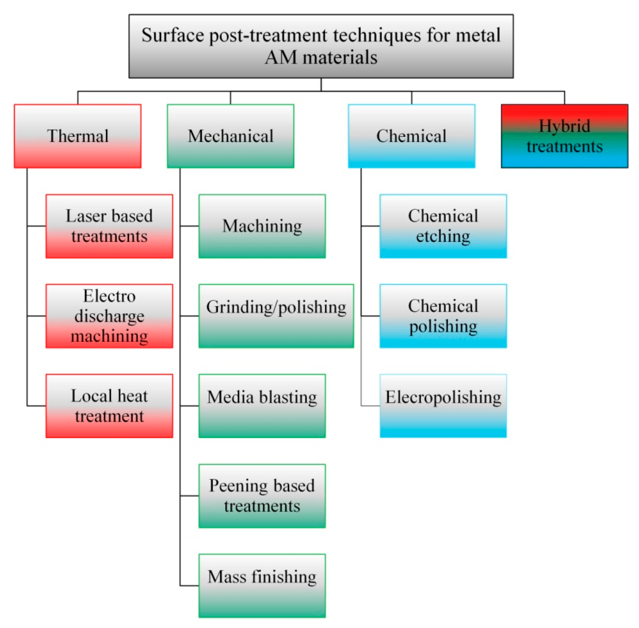
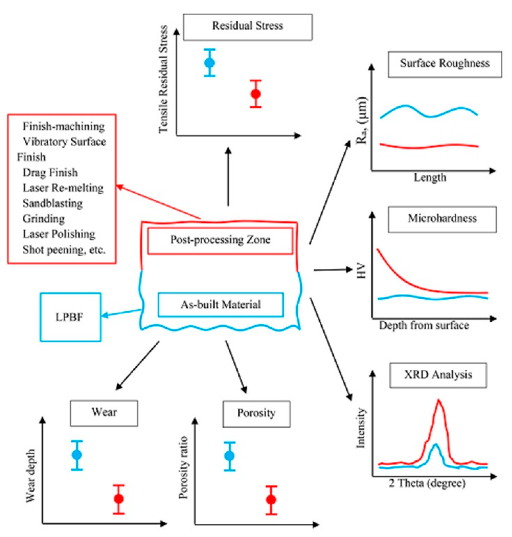
4.2. Surface Post-Treatment Techniques for Metal AM Parts

In the context of metal AM, post-processing refers to the various processes that 3D-printed parts must undergo before being put into service, such as powder removal, stress relief annealing, wire cutting, heat treatment, etc. The ideal choice of a post-treatment method is influenced by various factors, including surface quality, the time available to produce the desired surface quality, material properties, the post-treatment cost, the part shape, and the target function of the AM component [94,95,96,97].
Currently, the application of surface post-treatments has been shown to be quite efficient in resolving the issues associated with the uneven surface morphology of metallic objects produced using AM. Surface post-processing reduces surface roughness and porosity, making the material more resilient against fracture initiation and propagation and thereby increasing fatigue life [98,99]. Different parts may require different surface treatments based on the size, complexity, and desired properties. Overall, the choice of surface post-treatment technique also depends on the specific application requirements and the material properties of the metal AM part [100,101]. Following a literature review, surface post-processing techniques have been classified, as shown in Figure 27.
The surface integrity, porosity, and tensile residual stresses of metal AM samples are all affected differently by common surface post-processing techniques. Figure 28 depicts how surface post-processing procedures affect the surface characteristics of AM components.
Moreover, Table 3 summarizes surface post-processing techniques based on their benefits, limitations, important parameters, and applications.
Laser polishing can reduce porosity, improve surface integrity (Figure 29), enhance the residual stress distribution, and improve the dimensional stability and distortion control of the parts. However, it may also induce detrimental tensile stresses on the surface [100,105].
To date, laser polishing has proven effective in enhancing the surface integrity of metallic parts produced via AM. This technique has been successfully applied to various metals such as Ni, Ti, steel, and Al alloys [110].
Mechanical-based methods such as blasting, drag finishing, machining, and shot peening have been applied and studied for AM parts [80]. These techniques have a significant impact on the tiny layers near the surface of the AM parts by creating a protective layer with a refined grain structure and transforming residual stresses in AM metals from tensile to compressive, preventing failures due to fatigue, cracking, and stress corrosion and, thus, extending the life of a 3D-printed part [105]. Kaynak performed a comparative study to evaluate different mechanical-based surface post-treatments, such as finish machining under dry and cold air conditions, vibratory surface finishing, and drag finishing using ceramic abrasives to investigate surface roughness and hardness variation along the sample depth. The results (Figure 30) showed that drag finishing reduced the surface roughness and proved the most promising post-processing technique for achieving high surface quality for complex geometries. However, this method could not alter the subsurface characteristics profoundly [100].
The intended subsurface properties for the mechanical surface treatments may include defects’ status, e.g., dislocation density and grain morphology. Figure 31 illustrates the effect of laser polishing and shot peening as post-treatments on grain features and the distribution of crystal defects of stainless steel AM parts.
As depicted in the figure, the grain boundary length for the shot-peened sample was higher than the corresponding lengths of the others, which can be attributed to the severe surface plastic deformation due to shot peening [105].
It is worth mentioning that applying mechanical-based techniques to the internal structures of parts can be challenging due to mechanical treatments requiring surface-to-surface interactions. This is particularly true for specialized porous structures designed for biomedical applications or lattice structures intended for lightweight designs. In addition, these techniques used to reduce surface roughness can increase the time and cost involved in an already expensive process, which can further impede the widespread adoption of AM in the industry [94,98,100].
Some chemical-based approaches, such as chemical polishing or electrochemical polishing, have been effectively used for complicated geometries or small feature sections to guarantee that all component portions are thoroughly treated. The two processes have exhibited considerable promise in this sector (Figure 32). Compared to chemical polishing, electropolishing yields a smoother surface; nonetheless, its effectiveness is restricted due to the difficulty of inserting a counter-electrode into narrow or complex geometries. Surface roughness is more favorable in such cases and can significantly improve surface roughness [106]. Therefore, the treated object’s shape and geometry can significantly impact the efficacy and uniformity of chemical treatments [87].
The effect of different surface post-treatments on the surface morphology and corrosion properties of AM stainless steel is shown in Figure 33. The electropolishing and planar grinding surface finish treatments provided the largest reductions in surface roughness and increased corrosion properties [106].
The effect of different post-treatment techniques on corrosion behavior is schematically shown in Figure 34. In summary, a mechanical-based method affects surface roughness, residual stresses, and the density of crystal defects, such as grain boundaries and dislocations on the surface [105].
It should be highlighted that, in various situations, a single surface treatment may not accomplish all the required qualities for an AM metallic product. Combining several approaches with complex constraints may be advantageous to establish a superior technique. As a result, depending on the specific requirements of the ultimate application, different post-treatments may be combined to produce the necessary surface or bulk characteristics for the material [80,83].
The synergistic impact of combining mechanical (shot peening) and chemical (electropolishing) surface post-processing processes, for example, can be utilized to enhance a part’s wear resistance and fatigue strength while also creating a smooth surface [111]. Another example, more specifically useful for aerospace applications, is combining heat treatment and surface post-treatment to improve the fatigue performance of AM metallic components. This approach has been shown to improve the robustness and reliability of AM metallic components in conditions requiring cyclic loading and repeated stress (Figure 35) [112,113].

4.3. Challenges and Future Prospects

Several challenges and limitations are associated with surface post-processing techniques, which the market has been working to overcome through various means. The lengthy duration of the procedure is one of the most significant obstacles. Furthermore, the accuracy of surface post-processing techniques is restricted due to the original data quality; therefore, results may be imprecise if the data are inadequate. Another obstacle is the high cost associated with some surface post-processing techniques, which may make them inaccessible to smaller companies or researchers. Furthermore, the lack of standardization in surface post-processing makes it challenging to compare results across different studies.
That being said, some surface post-processing techniques for metal AM still rely on a manual operation that requires highly competent operators for crucial duties. On the first look, making a prototype or a few pieces by hand may be more cost-effective. However, as hundreds or thousands of components are produced, the requirement for post-processing automation in AM becomes increasingly urgent [80,87,114]. To overcome these challenges, researchers and the industry have developed new algorithms and technologies to simplify surface post-processing, such as machine learning approaches that automate key elements of the process, lowering the time and resources necessary. Furthermore, efforts are continuing to develop standardized methods for post-processing, which will allow for study comparisons [94].
As previously stated, future research (Figure 36) is leaning towards novel or hybrid surface post-treatments, in-line post-processing, automated solutions, online monitoring, and control system processes to increase as-built material quality. These strategies are linked and can enhance manufacturing efficiency [77,80,94,115].
Several companies have also started to employ robotic solutions for installing printing substrates, cleaning powder, unloading components, and post-processing. The search for automated methods has been a significant concern for many industry executives. These automated operations free up labor that may be employed in more crucial tasks [116].
It is worth noting that introducing online monitoring measures during the production process is one way to improve end-product quality and reduce material waste. Producers may take corrective measures instantly by identifying errors and defects online, reducing the need for reworking or material scrapping. This method has the potential to increase overall product quality and minimize the occurrence of problems. As a result, the objective is to eliminate all manual labor to encourage continuous and large-scale manufacturing [117].
Furthermore, machine learning has met with substantial interest in the AM sector, particularly in detecting process anomalies, sample defects, geometric distortions, and the formation of melt pool tracks. Machine learning methods can help recognize trends and abnormalities in data collected from AM operations that would be difficult to detect using conventional techniques [118]. While there has been significant improvement in this area, the rate at which innovation occurs is still very modest. However, as the industry expands and evolves, the number of surface post-processing options for AM is anticipated to increase.

5. Conclusions

Even though the AM of metal parts is typically presented as a new manufacturing method, the approach represents a novel and distinctive development in the field of metallurgy. In other words, with its complex thermal history, AM processes for metal parts are directly or indirectly dependent on metallurgical developments. Therefore, addressing the metallurgical aspects of this production method is very crucial to AM experts.
In summary, this text aimed to examine the metallurgical aspects of the AM method in three categories: the possibility of developing new alloys, creating functional parts, and improving the surface properties of printed products. The development of new alloys using powder of pure elements, of alloys, or of a mixture of these has been introduced as a pivotal solution to increase the flexibility of the AM method and reduce production costs. The possibility of developing a desired alloy, based on the material application and according to the ordered requirements, can be considered an achievable prospect.
Meanwhile, the solidification behavior of the new composition should be investigated and controlled according to the unique features of the AM method of metal parts, such as a high cooling speed and high thermal gradient. The creation of a concentration layer in front of the solidification front and its effect on the formation of a chemical under cooling and, as a result, the morphology of the resulting microstructure, are the fundamental points during alloy development. Also, some studies have considered the possibility of unwanted phases forming in the molten pool and how to eliminate the potentially detrimental precipitates. In contrast, others have tried turning the situation into an opportunity by using the secondary phases as potential nucleates.
Also, the AM process can effectively meet industrial needs when it is necessary for the parts to have dissimilar chemical compositions in various areas, which are referred to as FGMs. It is worth noting that the efforts undertaken in producing FGM parts employing AM methods have resulted in the development of standards such as ISO/ASTM TR 52912. Although the DED process is frequently preferred to produce FGM parts due to higher flexibility in the composition control, various PBF mechanisms have recently been suggested to introduce constituent powders. Before adopting a production process, it is essential to have adequate knowledge of the service requirements, the metallurgical compatibility of the basic materials, and the potential defects. Each pair has specific metallurgical compatibility limitations that must be considered when designing the gradient structure. In this regard, it is well demonstrated that the CALPHAD method can be an effective tool to find the feasible gradient design between terminal alloys by accurately predicting phase compositions under the non-equilibrium conditions of the AM process. Therefore, designing FGM structures based on the CALPHAD method may be the breakthrough path in the future, in addition to studying the failure mechanisms of AMed FGMs, which have been poorly addressed so far.
Finally, the desired surface quality expected from an AM part applicable at an industrial level should be improved. The prospects for AM surface post-treatment technology are promising, and it will facilitate the production of high-quality metal components using AM for different engineering purposes. Selecting the appropriate surface post-treatment can be a complex task, and various factors must be considered, such as process parameters, material properties, geometric concerns and restrictions, scalability, and treatment costs. Future research in various areas, including new or hybrid surface post-treatment, is encouraged to achieve desired properties and open new manufacturing and product development avenues. Automation tools and software are also suggested, including simulation and modeling tools or machine learning.

Author Contributions

Conceptualization, A.S. and L.I.; methodology, M.H.M., R.G. and A.B.; validation, A.S. and M.H.M.; formal analysis, M.H.M., R.G. and A.B.; data curation, M.H.M., R.G., A.B. and M.T.; writing—original draft preparation, M.H.M., R.G., A.B. and M.T.; writing—review and editing, M.H.M., R.G., A.B., M.T., A.S. and L.I.; visualization, A.S. and L.I.; supervision, A.S. and L.I. All authors have read and agreed to the published version of the manuscript.

Funding

This research received no external funding.

Conflicts of Interest

The authors declare no conflicts of interest.

References

  1. Mosallanejad, M.H.; Abdi, A.; Karpasand, F.; Nassiri, N.; Iuliano, L.; Saboori, A. Additive Manufacturing of Titanium Alloys; Processability, Properties and Applications. Adv. Eng. Mater. 2023, 25, 2301122. [Google Scholar] [CrossRef]
  2. Dadkhah, M.; Tulliani, J.-M.; Saboori, A.; Iuliano, L. Additive manufacturing of ceramics: Advances, challenges, and outlook. J. Eur. Ceram. Soc. 2023, 43, 6635–6664. [Google Scholar] [CrossRef]
  3. Piscopo, G.; Atzeni, E.; Saboori, A.; Salmi, A. An Overview of the Process Mechanisms in the Laser Powder Directed Energy Deposition. Appl. Sci. 2022, 13, 117. [Google Scholar] [CrossRef]
  4. Gibson, I.; Rosen, D.W.; Stucker, B. Additive Manufacturing Technologies: Rapid Prototyping to Direct Digital Manufacturing, 1st ed.; Springer: Berlin/Heidelberg, Germany, 2009. [Google Scholar]
  5. Singh, R.; Gupta, A.; Tripathi, O.; Srivastava, S.; Singh, B.; Awasthi, A.; Rajput, S.; Sonia, P.; Singhal, P.; Saxena, K.K. Powder bed fusion process in additive manufacturing: An overview. Mater. Today Proc. 2020, 26, 3058–3070. [Google Scholar] [CrossRef]
  6. Mehrpouya, M.; Vosooghnia, A.; Dehghanghadikolaei, A.; Fotovvati, B. The benefits of additive manufacturing for sustainable design and production. In Sustainable Manufacturing; Elsevier: Amsterdam, The Netherlands, 2021; pp. 29–59. [Google Scholar] [CrossRef]
  7. Hoeges, S.; Zwiren, A.; Schade, C. Additive manufacturing using water atomized steel powders. Met. Powder Rep. 2017, 72, 111–117. [Google Scholar] [CrossRef]
  8. Sames, W.J.; List, F.A.; Pannala, S.; Dehoff, R.R.; Babu, S.S. The metallurgy and processing science of metal additive manufacturing. Int. Mater. Rev. 2016, 61, 315–360. [Google Scholar] [CrossRef]
  9. Wits, W.W.; Weitkamp, S.J.; van Es, J. Metal Additive Manufacturing of a High-pressure Micro-pump. Procedia CIRP 2013, 7, 252–257. [Google Scholar] [CrossRef]
  10. Lee, J.-Y.; An, J.; Chua, C.K. Fundamentals and applications of 3D printing for novel materials. Appl. Mater. Today 2017, 7, 120–133. [Google Scholar] [CrossRef]
  11. Li, Y.; Feng, Z.; Hao, L.; Huang, L.; Xin, C.; Wang, Y.; Bilotti, E.; Essa, K.; Zhang, H.; Li, Z.; et al. A Review on Functionally Graded Materials and Structures via Additive Manufacturing: From Multi-Scale Design to Versatile Functional Properties. Adv. Mater. Technol. 2020, 5, 1900981. [Google Scholar] [CrossRef]
  12. Methani, M.M.; Revilla-León, M.; Zandinejad, A. The potential of additive manufacturing technologies and their processing parameters for the fabrication of all-ceramic crowns: A review. J. Esthet. Restor. Dent. 2019, 32, 182–192. [Google Scholar] [CrossRef] [PubMed]
  13. Yakout, M.; Elbestawi, M.; Veldhuis, S.C. A Review of Metal Additive Manufacturing Technologies. Solid State Phenom. 2018, 278, 1–14. [Google Scholar]
  14. Blinn, B.; Klein, M.; Gläßner, C.; Smaga, M.; Aurich, J.C.; Beck, T. An Investigation of the Microstructure and Fatigue Behavior of Additively Manufactured AISI 316L Stainless Steel with Regard to the Influence of Heat Treatment. Metals 2018, 8, 220. [Google Scholar] [CrossRef]
  15. Saboori, A.; Aversa, A.; Marchese, G.; Biamino, S.; Lombardi, M.; Fino, P. Microstructure and Mechanical Properties of AISI 316L Produced by Directed Energy Deposition-Based Additive Manufacturing: A Review. Appl. Sci. 2020, 10, 3310. [Google Scholar] [CrossRef]
  16. Gorsse, S.; Hutchinson, C.; Gouné, M.; Banerjee, R. Additive manufacturing of metals: A brief review of the characteristic microstructures and properties of steels, Ti-6Al-4V and high-entropy alloys. Sci. Technol. Adv. Mater. 2017, 18, 584–610. [Google Scholar] [CrossRef] [PubMed]
  17. Prado-Cerqueira, J.L.; Camacho, A.M.; Diéguez, J.L.; Rodríguez-Prieto, Á.; Aragón, A.M.; Lorenzo-Martín, C.; Yanguas-Gil, Á. Analysis of Favorable Process Conditions for the Manufacturing of Thin-Wall Pieces of Mild Steel Obtained by Wire and Arc Additive Manufacturing (WAAM). Materials 2018, 11, 1449. [Google Scholar] [CrossRef] [PubMed]
  18. Vayre, B.; Vignat, F.; Villeneuve, F. Designing for Additive Manufacturing. Procedia CIRP 2012, 3, 632–637. [Google Scholar] [CrossRef]
  19. Herderick, E.D. Additive Manufacturing of Metals: A Review. Mater. Sci. Technol. Conf. Exhib. 2011, 2, 1413–1425. [Google Scholar]
  20. DebRoy, T.; Wei, H.L.; Zuback, J.S.; Mukherjee, T.; Elmer, J.W.; Milewski, J.O.; Beese, A.M.; Wilson-Heid, A.; De, A.; Zhang, W. Additive manufacturing of metallic components–Process, structure and properties. Prog. Mater. Sci. 2018, 92, 112–224. [Google Scholar] [CrossRef]
  21. Taghian, M.; Mosallanejad, M.H.; Lannunziata, E.; Del Greco, G.; Iuliano, L.; Saboori, A. Laser powder bed fusion of metallic components: Latest progress in productivity, quality, and cost perspectives. J. Mater. Res. Technol. 2023, 27, 6484–6500. [Google Scholar] [CrossRef]
  22. Paul, M.J. Mechanical Anisotropy in Additive Manufactured Materials. Ph.D. Thesis, UNSW Sydney, Sydney, Australia, 2023. [Google Scholar] [CrossRef]
  23. Pragana, J.; Sampaio, R.; Bragança, I.; Silva, C.; Martins, P. Hybrid metal additive manufacturing: A state–of–the-art review. Adv. Ind. Manuf. Eng. 2021, 2, 100032. [Google Scholar] [CrossRef]
  24. Ghorbani, H.R.; Mosallanejad, M.H.; Atapour, M.; Galati, M.; Saboori, A. Hybrid additive manufacturing of an electron beam powder bed fused Ti6Al4V by transient liquid phase bonding. J. Mater. Res. Technol. 2022, 20, 180–194. [Google Scholar] [CrossRef]
  25. Chakravarthy, C.; Aranha, D.; Malyala, S.K.; Patil, R.S. Cast Metal Surgical Guides: An Affordable Adjunct to Oral and Maxillofacial Surgery. Craniomaxillofacial Trauma Reconstr. Open 2020, 5, 2472751220960268. [Google Scholar] [CrossRef]
  26. Bourell, D.; Kruth, J.P.; Leu, M.; Levy, G.; Rosen, D.; Beese, A.M.; Clare, A. Materials for additive manufacturing. CIRP Ann. Manuf. Technol. 2017, 66, 659–681. [Google Scholar] [CrossRef]
  27. Mosallanejad, M.H.; Niroumand, B.; Aversa, A.; Saboori, A. In-situ alloying in laser-based additive manufacturing processes: A critical review. J. Alloys Compd. 2021, 872, 159567. [Google Scholar] [CrossRef]
  28. Borkar, T.; Conteri, R.; Chen, X.; Ramanujan, R.V.; Banerjee, R. Laser additive processing of functionally-graded Fe–Si–B–Cu–Nb soft magnetic materials. Mater. Manuf. Process. 2016, 32, 1581–1587. [Google Scholar] [CrossRef]
  29. Zhang, D.; Qiu, D.; Gibson, M.A.; Zheng, Y.; Fraser, H.L.; StJohn, D.H.; Easton, M.A. Additive manufacturing of ultrafine-grained high-strength titanium alloys. Nature 2019, 576, 91–95. [Google Scholar] [CrossRef] [PubMed]
  30. Zhang, T.; Huang, Z.; Yang, T.; Kong, H.; Luan, J.; Wang, A.; Wang, D.; Kuo, W.; Wang, Y.; Liu, C.-T. In situ design of advanced titanium alloy with concentration modulations by additive manufacturing. Science 2021, 374, 478–482. [Google Scholar] [CrossRef] [PubMed]
  31. Mosallanejad, M.H.; Niroumand, B.; Ghibaudo, C.; Biamino, S.; Salmi, A.; Fino, P.; Saboori, A. In-situ alloying of a fine grained fully equiaxed Ti-based alloy via electron beam powder bed fusion additive manufacturing process. Addit. Manuf. 2022, 56, 102878. [Google Scholar] [CrossRef]
  32. Liu, Z.; Zhou, Q.; Liang, X.; Wang, X.; Li, G.; Vanmeensel, K.; Xie, J. Alloy design for laser powder bed fusion additive manufacturing: A critical review. Int. J. Extreme Manuf. 2023, 6, 022002. [Google Scholar] [CrossRef]
  33. Le, T.-N.; Lo, Y.-L. Effects of sulfur concentration and Marangoni convection on melt-pool formation in transition mode of selective laser melting process. Mater. Des. 2019, 179, 107866. [Google Scholar] [CrossRef]
  34. Sun, Z.; Tan, X.; Tor, S.B.; Chua, C.K. Simultaneously enhanced strength and ductility for 3D-printed stainless steel 316L by selective laser melting. NPG Asia Mater. 2018, 10, 127–136. [Google Scholar] [CrossRef]
  35. Alabort, E.; Tang, Y.; Barba, D.; Reed, R. Alloys-by-design: A low-modulus titanium alloy for additively manufactured biomedical implants. Acta Mater. 2022, 229, 117749. [Google Scholar] [CrossRef]
  36. Bandyopadhyay, A.; Traxel, K.D.; Lang, M.; Juhasz, M.; Eliaz, N.; Bose, S. Alloy design via additive manufacturing: Advantages, challenges, applications and perspectives. Mater. Today 2022, 52, 207–224. [Google Scholar] [CrossRef]
  37. Sing, S.; Huang, S.; Goh, G.; Tey, C.; Tan, J.; Yeong, W. Emerging metallic systems for additive manufacturing: In-situ alloying and multi-metal processing in laser powder bed fusion. Prog. Mater. Sci. 2021, 119, 100795. [Google Scholar] [CrossRef]
  38. Xu, J.-Y.; Zhang, P.-C.; Guo, R.; Liu, L.-X.; Kang, Y.-P.; Liu, Z.; Zhang, C.; Liu, L. Toughening the additively manufactured Al alloys via manipulating microstructural heterogeneity. J. Alloys Compd. 2023, 945, 169322. [Google Scholar] [CrossRef]
  39. Clare, A.; Mishra, R.; Merklein, M.; Tan, H.; Todd, I.; Chechik, L.; Li, J.; Bambach, M. Alloy design and adaptation for additive manufacture. J. Am. Acad. Dermatol. 2021, 299, 117358. [Google Scholar] [CrossRef]
  40. Li, H.; Brodie, E.G.; Hutchinson, C. Predicting the chemical homogeneity in laser powder bed fusion (LPBF) of mixed powders after remelting. Addit. Manuf. 2023, 65, 103447. [Google Scholar] [CrossRef]
  41. Mosallanejad, M.H.; Sanaei, S.; Atapour, M.; Niroumand, B.; Iuliano, L.; Saboori, A. Microstructure and Corrosion Properties of CP-Ti Processed by Laser Powder Bed Fusion under Similar Energy Densities. Acta Met. Sin. English Lett. 2022, 35, 1453–1464. [Google Scholar] [CrossRef]
  42. Maxwell, I.; Hellawell, A. A simple model for grain refinement during solidification. Acta Met. 1975, 23, 229–237. [Google Scholar] [CrossRef]
  43. Mendoza, M.Y.; Samimi, P.; Brice, D.A.; Martin, B.W.; Rolchigo, M.R.; LeSar, R.; Collins, P.C. Microstructures and Grain Refinement of Additive-Manufactured Ti-xW Alloys. Met. Mater. Trans. A 2017, 48, 3594–3605. [Google Scholar] [CrossRef]
  44. Mantri, S.A.; Alam, T.; Choudhuri, D.; Yannetta, C.J.; Mikler, C.V.; Collins, P.C.; Banerjee, R. The effect of boron on the grain size and texture in additively manufactured β-Ti alloys. J. Mater. Sci. 2017, 52, 12455–12466. [Google Scholar] [CrossRef]
  45. Han, Y.; Wang, H.-R.; Cao, Y.-D.; Hou, W.-T.; Li, S.-J. Improved Corrosion Resistance of Selective Laser Melted Ti–5Cu Alloy Using Atomized Ti–5Cu Powder. Acta Met. Sin. English Lett. 2019, 32, 1007–1014. [Google Scholar] [CrossRef]
  46. Mosallanejad, M.; Niroumand, B.; Aversa, A.; Manfredi, D.; Saboori, A. Laser Powder Bed Fusion in-situ alloying of Ti-5%Cu alloy: Process-structure relationships. J. Alloys Compd. 2020, 857, 157558. [Google Scholar] [CrossRef]
  47. Vilardell, A.M.; Yadroitsev, I.; Yadroitsava, I.; Albu, M.; Takata, N.; Kobashi, M.; Krakhmalev, P.; Kouprianoff, D.; Kothleitner, G.; du Plessis, A. Manufacturing and characterization of in-situ alloyed Ti6Al4V(ELI)-3 at.% Cu by laser powder bed fusion. Addit. Manuf. 2020, 36, 101436. [Google Scholar] [CrossRef]
  48. Yadroitsev, I.; Krakhmalev, P.; Yadroitsava, I. Titanium Alloys Manufactured by In Situ Alloying During Laser Powder Bed Fusion. JOM 2017, 69, 2725–2730. [Google Scholar] [CrossRef]
  49. Zhao, Y.; Ma, Z.; Yu, L.; Liu, Y. New alloy design approach to inhibiting hot cracking in laser additive manufactured nickel-based superalloys. Acta Mater. 2023, 247, 118736. [Google Scholar] [CrossRef]
  50. Zhang, J.; Gao, J.; Yang, S.; Song, B.; Zhang, L.; Lu, J.; Shi, Y. Breaking the strength–ductility trade-off in additively manufactured aluminum alloys through grain structure control by duplex nucleation. J. Mater. Sci. Technol. 2023, 152, 201–211. [Google Scholar] [CrossRef]
  51. Li, R.; Yue, H.; Luo, S.; Zhang, F.; Sun, B. Microstructure and mechanical properties of in situ synthesized (TiB+TiC)-reinforced Ti6Al4V composites produced by directed energy deposition of Ti and B4C powders. Mater. Sci. Eng. A 2023, 864, 144466. [Google Scholar] [CrossRef]
  52. Ghanavati, R.; Naffakh-Moosavy, H. Additive manufacturing of functionally graded metallic materials: A review of experimental and numerical studies. J. Mater. Res. Technol. 2021, 13, 1628–1664. [Google Scholar] [CrossRef]
  53. Ghanavati, R.; Naffakh-Moosavy, H.; Moradi, M.; Gadalińska, E.; Saboori, A. Residual stresses and distortion in additively-manufactured SS316L-IN718 multi-material by laser-directed energy deposition: A validated numerical-statistical approach. J. Manuf. Process. 2023, 108, 292–309. [Google Scholar] [CrossRef]
  54. Ji, W.; Zhou, R.; Vivegananthan, P.; Wu, M.S.; Gao, H.; Zhou, K. Recent progress in gradient-structured metals and alloys. Prog. Mater. Sci. 2023, 140, 101194. [Google Scholar] [CrossRef]
  55. Tian, X.; Zhao, Z.; Wang, H.; Liu, X.; Song, X. Progresses on the additive manufacturing of functionally graded metallic materials. J. Alloys Compd. 2023, 960, 170687. [Google Scholar] [CrossRef]
  56. Bhavar, V.; Kattire, P.; Thakare, S.; Patil, S.; Singh, R.K.P. A Review on Functionally Gradient Materials (FGMs) and Their Applications. IOP Conf. Series Mater. Sci. Eng. 2017, 229, 012021. [Google Scholar] [CrossRef]
  57. Zhang, C.; Chen, F.; Huang, Z.; Jia, M.; Chen, G.; Ye, Y.; Lin, Y.; Liu, W.; Chen, B.; Shen, Q.; et al. Additive manufacturing of functionally graded materials: A review. Mater. Sci. Eng. A 2019, 764, 138209. [Google Scholar] [CrossRef]
  58. Koizumi, M. FGM activities in Japan. Compos. Part B Eng. 1997, 28, 1–4. [Google Scholar] [CrossRef]
  59. Hazan, E.; Ben-Yehuda, O.; Madar, N.; Gelbstein, Y. Functional Graded Germanium-Lead Chalcogenide-Based Thermoelectric Module for Renewable Energy Applications. Adv. Energy Mater. 2015, 5, 1500272. [Google Scholar] [CrossRef]
  60. Kumar, S.; Reddy, K.M.; Kumar, A.; Devi, G.R. Development and characterization of polymer–ceramic continuous fiber reinforced functionally graded composites for aerospace application. Aerosp. Sci. Technol. 2012, 26, 185–191. [Google Scholar] [CrossRef]
  61. Lima, D.; Mantri, S.; Mikler, C.; Contieri, R.; Yannetta, C.; Campo, K.; Lopes, E.; Styles, M.; Borkar, T.; Caram, R.; et al. Laser additive processing of a functionally graded internal fracture fixation plate. Mater. Des. 2017, 130, 8–15. [Google Scholar] [CrossRef]
  62. Hofmann, D.C.; Kolodziejska, J.; Roberts, S.; Otis, R.; Dillon, R.P.; Suh, J.-O.; Liu, Z.-K.; Borgonia, J.-P. Compositionally graded metals: A new frontier of additive manufacturing. J. Mater. Res. 2014, 29, 1899–1910. [Google Scholar] [CrossRef]
  63. Ansari, M.; Jabari, E.; Toyserkani, E. Opportunities and challenges in additive manufacturing of functionally graded metallic materials via powder-fed laser directed energy deposition: A review. J. Mater. Process. Technol. 2021, 294, 117117. [Google Scholar] [CrossRef]
  64. Naebe, M.; Shirvanimoghaddam, K. Functionally graded materials: A review of fabrication and properties. Appl. Mater. Today 2016, 5, 223–245. [Google Scholar] [CrossRef]
  65. Ma, Z.; Liu, W.; Li, W.; Liu, H.; Song, J.; Liu, Y.; Huang, Y.; Xia, Y.; Wang, Z.; Liu, S.; et al. Additive manufacturing of functional gradient materials: A review of research progress and challenges. J. Alloys Compd. 2024, 971, 172642. [Google Scholar] [CrossRef]
  66. Feenstra, D.; Banerjee, R.; Fraser, H.; Huang, A.; Molotnikov, A.; Birbilis, N. Critical review of the state of the art in multi-material fabrication via directed energy deposition. Curr. Opin. Solid State Mater. Sci. 2021, 25, 100924. [Google Scholar] [CrossRef]
  67. Mehrabi, O.; Seyedkashi, S.M.H.; Moradi, M. Functionally Graded Additive Manufacturing of Thin-Walled 316L Stainless Steel-Inconel 625 by Direct Laser Metal Deposition Process: Characterization and Evaluation. Metals 2023, 13, 1108. [Google Scholar] [CrossRef]
  68. Schneck, M.; Horn, M.; Schmitt, M.; Seidel, C.; Schlick, G.; Reinhart, G. Review on additive hybrid- and multi-material-manufacturing of metals by powder bed fusion: State of technology and development potential. Prog. Addit. Manuf. 2021, 6, 881–894. [Google Scholar] [CrossRef]
  69. Wei, C.; Li, L. Recent progress and scientific challenges in multi-material additive manufacturing via laser-based powder bed fusion. Virtual Phys. Prototyp. 2021, 16, 347–371. [Google Scholar] [CrossRef]
  70. ISO/ASTM TR 52912; Additive Manufacturing—Design—Functionally Graded Additive Manufacturing. ISO: Geneva, Switzerland, 2020.
  71. Reichardt, A.; Shapiro, A.A.; Otis, R.; Dillon, R.P.; Borgonia, J.P.; McEnerney, B.W.; Hosemann, P.; Beese, A.M. Advances in additive manufacturing of metal-based functionally graded materials. Int. Mater. Rev. 2020, 66, 1–29. [Google Scholar] [CrossRef]
  72. Ghanavati, R.; Lannunziata, E.; Norouzi, E.; Bagherifard, S.; Iuliano, L.; Saboori, A. Design and development of SS316L-IN718 functionally graded materials via laser powder bed fusion. Mater. Lett. 2023, 349, 134793. [Google Scholar] [CrossRef]
  73. Alkunte, S.; Fidan, I.; Naikwadi, V.; Gudavasov, S.; Ali, M.A.; Mahmudov, M.; Hasanov, S.; Cheepu, M. Advancements and Challenges in Additively Manufactured Functionally Graded Materials: A Comprehensive Review. J. Manuf. Mater. Process. 2024, 8, 23. [Google Scholar] [CrossRef]
  74. Bobbio, L.D.; Bocklund, B.; Otis, R.; Borgonia, J.P.; Dillon, R.P.; Shapiro, A.A.; McEnerney, B.; Liu, Z.-K.; Beese, A.M. Characterization of a functionally graded material of Ti-6Al-4V to 304L stainless steel with an intermediate V section. J. Alloys Compd. 2018, 742, 1031–1036. [Google Scholar] [CrossRef]
  75. Eliseeva, O.; Kirk, T.; Samimi, P.; Malak, R.; Arróyave, R.; Elwany, A.; Karaman, I. Functionally Graded Materials through robotics-inspired path planning. Mater. Des. 2019, 182, 107975. [Google Scholar] [CrossRef]
  76. Bobbio, L.D.; Bocklund, B.; Simsek, E.; Ott, R.T.; Kramer, M.J.; Liu, Z.-K.; Beese, A.M. Design of an additively manufactured functionally graded material of 316 stainless steel and Ti-6Al-4V with Ni-20Cr, Cr, and V intermediate compositions. Addit. Manuf. 2022, 51, 102649. [Google Scholar] [CrossRef]
  77. Gao, W.; Zhang, Y.; Ramanujan, D.; Ramani, K.; Chen, Y.; Williams, C.B.; Wang, C.C.L.; Shin, Y.C.; Zhang, S.; Zavattieri, P.D. The status challenges, and future of additive manufacturing in engineering. Comput.-Aided Des. 2015, 69, 65–89. [Google Scholar] [CrossRef]
  78. Herzog, D.; Seyda, V.; Wycisk, E.; Emmelmann, C. Additive manufacturing of metals. Acta Mater. 2016, 117, 371–392. [Google Scholar] [CrossRef]
  79. Dadkhah, M.; Mosallanejad, M.H.; Iuliano, L.; Saboori, A. A Comprehensive Overview on the Latest Progress in the Additive Manufacturing of Metal Matrix Composites: Potential, Challenges, and Feasible Solutions. Acta Met. Sin. English Lett. 2021, 34, 1173–1200. [Google Scholar] [CrossRef]
  80. Maleki, E.; Bagherifard, S.; Bandini, M.; Guagliano, M. Surface post-treatments for metal additive manufacturing: Progress, challenges, and opportunities. Addit. Manuf. 2020, 37, 101619. [Google Scholar] [CrossRef]
  81. Denti, L.; Bassoli, E.; Gatto, A.; Santecchia, E.; Mengucci, P. Fatigue life and microstructure of additive manufactured Ti6Al4V after different finishing processes. Mater. Sci. Eng. A 2019, 755, 1–9. [Google Scholar] [CrossRef]
  82. Yap, C.Y.; Chua, C.K.; Dong, Z.L.; Liu, Z.H.; Zhang, D.Q.; Loh, L.E.; Sing, S.L. Review of selective laser melting: Materials and applications. Appl. Phys. Rev. 2015, 2, 041101. [Google Scholar] [CrossRef]
  83. Abdulhameed, O.; Al-Ahmari, A.; Ameen, W.; Mian, S.H. Additive manufacturing: Challenges, trends, and applications. Adv. Mech. Eng. 2019, 11, 1–27. [Google Scholar] [CrossRef]
  84. Yadollahi, A.; Shamsaei, N. Additive manufacturing of fatigue resistant materials: Challenges and opportunities. Int. J. Fatigue 2017, 98, 14–31. [Google Scholar] [CrossRef]
  85. Chen, S.-G.; Gao, H.-J.; Zhang, Y.-D.; Wu, Q.; Gao, Z.-H.; Zhou, X. Review on residual stresses in metal additive manufacturing: Formation mechanisms, parameter dependencies, prediction and control approaches. J. Mater. Res. Technol. 2022, 17, 2950–2974. [Google Scholar] [CrossRef]
  86. Simson, T.; Emmel, A.; Dwars, A.; Böhm, J. Residual stress measurements on AISI 316L samples manufactured by selective laser melting. Addit. Manuf. 2017, 17, 183–189. [Google Scholar] [CrossRef]
  87. Lee, J.-Y.; Nagalingam, A.P.; Yeo, S.H. A review on the state-of-the-art of surface finishing processes and related ISO/ASTM standards for metal additive manufactured components. Virtual Phys. Prototyp. 2020, 16, 68–96. [Google Scholar] [CrossRef]
  88. Galati, M.; Defanti, S.; Saboori, A.; Rizza, G.; Tognoli, E.; Vincenzi, N.; Gatto, A.; Iuliano, L. An investigation on the processing conditions of Ti-6Al-2Sn-4Zr-2Mo by electron beam powder bed fusion: Microstructure, defect distribution, mechanical properties and dimensional accuracy. Addit. Manuf. 2021, 50, 102564. [Google Scholar] [CrossRef]
  89. Behjat, A.; Shamanian, M.; Sadeghi, F.; Iuliano, L.; Saboori, A. Additive manufacturing of a novel in-situ alloyed AISI316L-Cu stainless steel: Microstructure and antibacterial properties. Mater. Lett. 2024, 355, 135363. [Google Scholar] [CrossRef]
  90. Ye, C.; Zhang, C.; Zhao, J.; Dong, Y. Effects of Post-processing on the Surface Finish, Porosity, Residual Stresses, and Fatigue Performance of Additive Manufactured Metals: A Review. J. Mater. Eng. Perform. 2021, 30, 6407–6425. [Google Scholar] [CrossRef] [PubMed]
  91. Mahmood, M.A.; Chioibasu, D.; Rehman, A.U.; Mihai, S.; Popescu, A.C. Post-Processing Techniques to Enhance the Quality of Metallic Parts Produced by Additive Manufacturing. Metals 2022, 12, 77. [Google Scholar] [CrossRef]
  92. Zhang, J.; Lee, Y.J.; Wang, H. A Brief Review on the Enhancement of Surface Finish for Metal Additive Manufacturing. J. Miner. Met. Mater. Eng. 2021, 7, 1–14. [Google Scholar]
  93. Basha, S.; Venkaiah, N.; Srivatsan, T.; Sankar, M. A review on severe plastic deformation based post-processes for metal additive manufactured complex features. Mater. Manuf. Process. 2023, 39, 291–309. [Google Scholar] [CrossRef]
  94. Peng, X.; Kong, L.; Fuh, J.Y.H.; Wang, H. A Review of Post-Processing Technologies in Additive Manufacturing. J. Manuf. Mater. Process. 2021, 5, 38. [Google Scholar] [CrossRef]
  95. Behjat, A.; Shamanian, M.; Taherizadeh, A.; Noori, M.; Lannunziata, E.; Iuliano, L.; Saboori, A. Enhanced surface properties and bioactivity of additively manufactured 316L stainless steel using different post-treatments. Mater. Today Proc. 2022, 70, 188–194. [Google Scholar] [CrossRef]
  96. Hashmi, A.W.; Mali, H.S.; Meena, A.; Saxena, K.K.; Ahmad, S.; Agrawal, M.K.; Sagbas, B.; Puerta, A.P.V.; Khan, M.I. A comprehensive review on surface post-treatments for freeform surfaces of bio-implants. J. Mater. Res. Technol. 2023, 23, 4866–4908. [Google Scholar] [CrossRef]
  97. Chowdhury, S.; Arunachalam, N. Surface functionalization of additively manufactured titanium alloy for orthopaedic implant applications. J. Manuf. Process. 2023, 102, 387–405. [Google Scholar] [CrossRef]
  98. Khan, H.M.; Karabulut, Y.; Kitay, O.; Kaynak, Y.; Jawahir, I.S. Influence of the post-processing operations on surface integrity of metal components produced by laser powder bed fusion additive manufacturing: A review. Mach. Sci. Technol. 2021, 25, 118–176. [Google Scholar] [CrossRef]
  99. Khosravani, M.R.; Ayatollahi, M.R.; Reinicke, T. Effects of post-processing techniques on the mechanical characterization of additively manufactured parts. J. Manuf. Process. 2023, 107, 98–114. [Google Scholar] [CrossRef]
  100. Kaynak, Y.; Kitay, O. The effect of post-processing operations on surface characteristics of 316L stainless steel produced by selective laser melting. Addit. Manuf. 2018, 26, 84–93. [Google Scholar] [CrossRef]
  101. Fayazfar, H.; Sharifi, J.; Keshavarz, M.K.; Ansari, M. An overview of surface roughness enhancement of additively manufactured metal parts: A path towards removing the post-print bottleneck for complex geometries. Int. J. Adv. Manuf. Technol. 2023, 125, 1061–1113. [Google Scholar] [CrossRef]
  102. Basha, S.; Bhuyan, M.; Basha, M.; Venkaiah, N.; Sankar, M. Laser polishing of 3D printed metallic components: A review on surface integrity. Mater. Today Proc. 2020, 26, 2047–2054. [Google Scholar] [CrossRef]
  103. Rosa, B.; Mognol, P.; Hascoët, J.-Y. Laser polishing of additive laser manufacturing surfaces. J. Laser Appl. 2015, 27, S29102. [Google Scholar] [CrossRef]
  104. Bhaduri, D.; Penchev, P.; Batal, A.; Dimov, S.; Soo, S.L.; Sten, S.; Harrysson, U.; Zhang, Z.; Dong, H. Laser polishing of 3D printed mesoscale components. Appl. Surf. Sci. 2017, 405, 29–46. [Google Scholar] [CrossRef]
  105. Behjat, A.; Shamanian, M.; Taherizadeh, A.; Lannunziata, E.; Bagherifard, S.; Gadalińska, E.; Saboori, A.; Iuliano, L. Microstructure-electrochemical behavior relationship in post processed AISI316L stainless steel parts fabricated by laser powder bed fusion. J. Mater. Res. Technol. 2023, 23, 3294–3311. [Google Scholar] [CrossRef]
  106. Tyagi, P.; Goulet, T.; Riso, C.; Stephenson, R.; Chuenprateep, N.; Schlitzer, J.; Benton, C.; Garcia-Moreno, F. Reducing the roughness of internal surface of an additive manufacturing produced 316 steel component by chempolishing and electropolishing. Addit. Manuf. 2018, 25, 32–38. [Google Scholar] [CrossRef]
  107. Melia, M.A.; Duran, J.G.; Koepke, J.R.; Saiz, D.J.; Jared, B.H.; Schindelholz, E.J. How build angle and post-processing impact roughness and corrosion of additively manufactured 316L stainless steel. Npj Mater. Degrad. 2020, 4, 21. [Google Scholar] [CrossRef]
  108. Han, W.; Fang, F. Fundamental aspects and recent developments in electropolishing. Int. J. Mach. Tools Manuf. 2019, 139, 1–23. [Google Scholar] [CrossRef]
  109. Yang, G.; Wang, B.; Tawfiq, K.; Wei, H.; Zhou, S.; Chen, G. Electropolishing of surfaces. Surf. Eng. 2017, 33, 149–166. [Google Scholar] [CrossRef]
  110. Marimuthu, S.; Triantaphyllou, A.; Antar, M.; Wimpenny, D.; Morton, H.; Beard, M. Laser polishing of selective laser melted components. Int. J. Mach. Tools Manuf. 2015, 95, 97–104. [Google Scholar] [CrossRef]
  111. Yan, C.; Hao, L.; Hussein, A.; Wei, Q.; Shi, Y. Microstructural and surface modifications and hydroxyapatite coating of Ti-6Al-4V triply periodic minimal surface lattices fabricated by selective laser melting. Mater. Sci. Eng. C 2017, 75, 1515–1524. [Google Scholar] [CrossRef]
  112. Nasab, M.H.; Giussani, A.; Gastaldi, D.; Tirelli, V.; Vedani, M. Effect of Surface and Subsurface Defects on Fatigue Behavior of AlSi10Mg Alloy Processed by Laser Powder Bed Fusion (L-PBF). Metals 2019, 9, 1063. [Google Scholar] [CrossRef]
  113. Maleki, E.; Bagherifard, S.; Unal, O.; Bandini, M.; Guagliano, M. The effects of microstructural and chemical surface gradients on fatigue performance of laser powder bed fusion AlSi10Mg. Mater. Sci. Eng. A 2022, 840, 142962. [Google Scholar] [CrossRef]
  114. Peng, X.; Kong, L.; An, H.; Dong, G. A Review of In Situ Defect Detection and Monitoring Technologies in Selective Laser Melting. 3D Print. Addit. Manuf. 2023, 10, 438–466. [Google Scholar] [CrossRef] [PubMed]
  115. Haley, J.; Karandikar, J.; Herberger, C.; MacDonald, E.; Feldhausen, T.; Lee, Y. Review of in situ process monitoring for metal hybrid directed energy deposition. J. Manuf. Process. 2024, 109, 128–139. [Google Scholar] [CrossRef]
  116. Ashima, R.; Haleem, A.; Bahl, S.; Javaid, M.; Mahla, S.K.; Singh, S. Automation and manufacturing of smart materials in additive manufacturing technologies using Internet of Things towards the adoption of industry 4.0. Mater. Today Proc. 2021, 45, 5081–5088. [Google Scholar] [CrossRef]
  117. Min, Y.; Shen, S.; Li, H.; Liu, S.; Mi, J.; Zhou, J.; Mai, Z.; Chen, J. Online monitoring of an additive manufacturing environment using a time-of-flight mass spectrometer. Measurement 2021, 189, 110473. [Google Scholar] [CrossRef]
  118. Goh, G.D.; Sing, S.L.; Yeong, W.Y. A Review on Machine Learning in 3D Printing: Applications, Potential, and Challenges. Artif. Intell. Rev. 2021, 54, 63–94. [Google Scholar] [CrossRef]
Figure 1. (a) The effect of Marangoni on the melt pool geometry based on the melt chemical composition, reprinted from Ref. [33] and (b) the influence of the melt pool geometry on the preferred orientation in alloys with a cubic crystal structure, reprinted from Ref. [34].
Metals 14 00425 g001
Figure 2. Schematic representation of (a) a Ti6Al4V alloy with a low growth restriction factor (Equation (1)), hence developing columnar grains under the steep thermal gradient experienced during the AM process, and (b) a modified alloy with a larger solidification range and higher value of growth restriction factor, leading to CET and equiaxed grains, reprinted from Ref. [35].
Metals 14 00425 g002
Figure 3. SEM images in BSE mode from different sample heights; W concentrations increased moving from (a) the substrate, (b,c) upward, reprinted from Ref. [43].
Metals 14 00425 g003
Figure 4. SEM images of (a) Ti-12 wt.% Mo and (b) Ti-12 wt.% Mo-0.5 wt.% B, reprinted with permission from Ref. [44]. 2017, Springer Nature.
Metals 14 00425 g004
Figure 5. CET in (a,b) Ti-20V, and Ti-12Mo alloys, (c,d) both alloys after adding trace amounts of boron particles, reprinted with permission from Ref. [44]. 2017, Springer Nature.
Metals 14 00425 g005
Figure 6. The heterogeneous structure in the Al–Fe–Cu–xZr alloys as observed using the EBSD method: (a) x = 0.6, (b) x = 0.6, (c) x = 0.8, and (d) x = 1.3, reprinted with permission from Ref. [38]. 2023, Elsevier.
Metals 14 00425 g006
Figure 7. True stress–stain curves of the Al–Fe–Cu–xZr alloys under tension, reprinted with permission from Ref. [38]. 2023, Elsevier.
Metals 14 00425 g007
Figure 8. Schematic representation of the thermal gradient experienced during the EBM method compared to other powder-based methods (i.e., LPBF and DED). The creation of different amounts of constitutional undercoolings (ΔTc > ΔTc’) ahead of the solidification front is also illustrated, reprinted with permission from Ref. [31]. 2022, Elsevier.
Metals 14 00425 g008
Figure 9. OM images of (a) Ti–6Al–4V and (b) Ti–6Al–4V-7 wt.% Cu, reprinted with permission from Ref. [31]. 2022, Elsevier.
Metals 14 00425 g009
Figure 10. Schematic illustration of intermetallic formation and grain refinement due to the rejection of B and C in Ti liquid during the (TiB + TiC)/Ti solidification process, reprinted with permission from Ref. [51]. 2023, Elsevier.
Metals 14 00425 g010
Figure 11. (a) Band contrast image showing the ultrafine fully equiaxed grain structure (side view) and (b) engineering stress–strain curves of as-built samples. The open symbols indicate the UTS points, reprinted with permission from Ref. [30]. 2021, Science.
Metals 14 00425 g011
Figure 12. The stages of continuous materials development, reprinted from Ref. [56].
Metals 14 00425 g012
Figure 13. Graphical diagrams of (a) discontinuous and (b) continuous FGMs. (ce) Schematic structures for discontinuous FGMs due to gradual changes in the chemical composition, grain orientation, and volume fraction of secondary phases, respectively. (fh) Schematic structures for continuous FGMs due to gradual changes in the grain size, fiber orientation, and volume fraction of secondary phases, respectively, reprinted with permission from Ref. [57]. 2019, Elsevier.
Metals 14 00425 g013
Figure 14. Various application areas for FGMs, reprinted from Ref. [52].
Metals 14 00425 g014
Figure 15. FGM prototypes from design to the final part: (ae) gradient rocket nozzle from Ti6Al4V alloy to Nb, (fj) gradient automotive valve stem from stainless steel 304L to Inconel 625, and (kn) gradient space mirror with isogrid backing from stainless steel 304L to Invar 36, reprinted with permission from Ref. [62]. 2014, Springer nature.
Metals 14 00425 g015
Figure 16. Outline of the conventional manufacturing (CM) methods’ mechanism for producing FGMs, reprinted from Ref. [11].
Metals 14 00425 g016
Figure 17. Categorization of the AM methods for FGMs’ fabrication.
Metals 14 00425 g017
Figure 18. Schematic of the L-DED process with separate powder feeders to fabricate FGMs, reprinted from Ref. [67].
Metals 14 00425 g018
Figure 19. Schematics of the material-spreading mechanisms in the PBF process compatible with compositional FGMs’ fabrication: (a) blade-based dual-powder recoater, (b) ultrasonic-based dual-powder dispenser, (c) electrophotographic-based dual-powder dispenser, and (d) “blade-ultrasonic” hybrid powder spreading, reprinted from Ref. [69].
Metals 14 00425 g019
Figure 20. Outline of the development of metallic FGMs via AM.
Metals 14 00425 g020
Figure 21. Different build designs for the AM of compositional FGMs: (a) linear, (b) bimetal, (c) recursive, (d) triple, and (e,f) dispersion and precipitation metal matrix composites (MMC), reprinted with permission from Ref. [62]. 2014, Springer Nature.
Metals 14 00425 g021
Figure 22. (a) Gradient design for the Ti6Al4V-304L stainless steel through the intermediate element of V. (b) Cross section of the cracked sample during fabrication. (c,d) EBSD phase maps associated with the locations marked in (b). (e,f) Equilibrium ternary phase diagrams of Ti–Fe–V and Cr–Fe–V at 1123 K, respectively, with linear gradient paths drawn on each one, reprinted with permission from Ref. [74]. 2018, Elsevier.
Metals 14 00425 g022
Figure 23. Application of isothermal ternary phase diagram for gradient design between terminal alloys 1 and 2. The yellow and green dotted lines as binary and arbitrary paths, respectively, avoid a detrimental γ phase, in contrast to the linear gradient (red dotted line), reprinted from Ref. [75].
Metals 14 00425 g023
Figure 24. Equilibrium and Scheil–Gulliver ternary phase diagrams of (a,b) Cr–Fe–Ti and (c,d) Fe–Ni–Ti systems. The white dashed line shows the linear path from Ti to a particular type of stainless steel, reprinted with permission from Ref. [76]. 2022, Elsevier.
Metals 14 00425 g024
Figure 25. The combination of ternary feasibility diagrams representing safe regions (without detrimental phases) to grade between 316L stainless steel and Ti6Al4V based on equilibrium and Scheil–Gulliver calculations, reprinted with permission from Ref. [76]. 2022, Elsevier.
Metals 14 00425 g025
Figure 26. Challenges in AM technology.
Metals 14 00425 g026
Figure 27. Categorization of the surface post-processing techniques for metal AM products.
Metals 14 00425 g027
Figure 28. Schematic representation of the post-processing operations’ effect on the surface characteristics of the as-built AM parts, reprinted with permission from ref. [98]. 2021, Taylor&Francis.
Metals 14 00425 g028
Figure 29. Roughness reduction via laser polishing: (a) SEM image showing the contrast between the original and polished surfaces and (b) the equivalent transition using the laser profilometer, reprinted with permission from Ref. [98]. 2021, Elsevier.
Metals 14 00425 g029
Figure 30. (a) The variation in average surface roughness and (b) microhardness variation after post-processes, reprinted with permission from Ref. [100]. 2018, Elsevier.
Metals 14 00425 g030
Figure 31. Inverse pole figure images with grain boundaries: (a) as-printed, (b) laser-polished, and (c) shot-peened; image quality with grain boundaries: (d) as-printed, (e) laser-polished, and (f) shot-peened, reprinted from Ref. [105].
Metals 14 00425 g031
Figure 32. (a) Outer surface texture, (b) internal surfaces of AM components with internal volume after electropolishing and chemical polishing, and (c) various surface roughness parameters of blasted, electropolished, and chemically polished AM components, reprinted with permission from Ref. [106]. 2018, Elsevier.
Metals 14 00425 g032
Figure 33. (a) BSE images and EBSD maps of surface cross-sections and (b) the relationship between breakdown potential and surface roughness, reprinted from Ref. [107].
Metals 14 00425 g033
Figure 34. Schematics of surface modifications and passive film formation on the surface of (a) as-printed, (b) ground, (c) laser-polished, and (d) shot-peened samples, reprinted from Ref. [105].
Metals 14 00425 g034
Figure 35. Fatigue life improvement in post-treated samples compared to the as-built state, reprinted with permission from Ref. [113]. 2022, Elsevier.
Metals 14 00425 g035
Figure 36. Future trends in surface post-processing of metal AM materials.
Metals 14 00425 g036
Table 1. Conventional manufacturing methods of FGMs, adopted from Ref. [3], and adopted with permission from Ref. [64]. 2016, Elsevier.
CategoryMethodType of FGM
Gas-based methodChemical vapor deposition (CVD)Thin film/coating
Physical vapor deposition (PVD)
Thermal spray
Surface reaction process
Liquid-phase processCentrifugal castingBulk
Gel casting
Sedimentation
Tape-casting
Slip casting
Electrophoretic deposition
Directional solidification
Solid-phase processPowder metallurgyBulk
Spark plasma sintering (SPS)
Other methodsSelf-propagating high-temperature synthesis (SHS)Thin film/coating
Plasma spraying
Electrode deposition
Ion beam-assisted deposition
Table 2. Cross-comparison of alloys’ compatibility associated with joining them.
Austenitic Stainless SteelMartensitic and Precipitation Stainless SteelLow Alloy SteelNickelAluminumCobaltCopperMagnesiumZirconiumRefractory Metals
TitaniumIM, TM, CTEIM, TMIM, TMIM, TMIM, TM, CTEIM, CTE *TM, CTEPS, TM, CTE, TCNone *TM, TC
Austenitic stainless steel-CTECTE, M, CM, SIM, CM, SIM, TM, CTE, TCNone *PS, CTE, TC, TMPS, TM, CTEIM, CTEIM, TM, CTE
Martensitic and precipitation stainless steel--CM, OMNoneIM, TM, CTE, TCNone *PS, TC, TMPS, TM, CTE *IM *IM, TM, CTE
Low alloy steel---M, CP, SIM, TM, CTE, TCNone *PS, TC, TMPS, TM, CTEIM *IM, TM, CTE
Nickel----IM, TM, CTE, TC *NoneTC, TMTM, CTE *IM *IM, TM, CTE
Aluminum-----IM, TM, CTE *IM, TMIMIM, TM, CTE *IM, TM, CTE
Cobalt------PS, TC *TM, CTE *IM, CTE *IM, TM, CTE *
Copper-------IM, TM, CTE, TCIM, TM, CTE, TC *PS, TM, CTE
Magnesium--------PS, TM, CTE *PS, TM, CTE *
Zirconium---------IM *
Refractory metals----------
Intermetallic formation and solubility limitationsThermal property mismatchOther metallurgical effects
IM: brittle intermetallic formationTM: melting temperature mismatchCM: carbon migration
PS: poor solubilityCTE: coefficient of thermal expansion mismatchOM: other species migration
TC: thermal conductivity mismatchCP: carbide precipitation
S: sensitization
M: martensite formation
* Limited data available.
Table 3. Summary of effects of surface post-processing for AM metals.
Surface Post-Processing MethodsProcess ParametersMain AdvantagesMain LimitationsApplications and ComplexityEffect on Surface Integrities
Laser polishing [98,102,103,104]Laser powder, spot size, scan speed, etc.Selective polishing of
small areas
Costly to operate; difficulty in
achieving uniform intensity profile
Suitable for flat and curved surfaces; low to medium complexityImproves surface finishes, decreases porosity, and results in tensile residual stresses
Media blasting [93,94,96]Blasting pressure,
velocity, grit
type, size, etc.
Removes only unsintered powders; applicable to a wide variety of materialsLow material removal rate; part
complexity
restrictions
Suitable for flat, external surface; low complexityIncreases surface roughness and improves hardness and fatigue performance
Peening: Use of laser or spherical shots [80,91,93,105] Peening material,
size, pressure,
velocity, etc.
Simple process; applicable to a wide variety of materialsPotential damage tothin partsComplicated
geometries
cannot be finished; low complexity
Improves the surface mechanical properties and converts tensile stresses to compressive stresses
Advanced finishing
and machining [90,100]
Machining speed, tool material, coolant, depth of cut, etc.Relatively inexpensive
and well understood
process
Not applicable to highly complex parts like scaffold structuresSuitable for shafts; low complexityImproves surface finish and hardness
Chemical polishing [80,106] Acid fluidconcentration
process time,
temperature, etc.
Suitable for complex
geometries
Extreme health
and safety issues due to oxidation
Used for scaffold surfaces and internal features; high complexityReduces surface roughness
Electro-polishing [107,108,109]Type of chemical, process time, temperature, etc.Cost-effective methodUtilizes hard
chemicals as
electrolytes
Suitable for free-form shapes with high complexityAchieves a
smooth surface
Disclaimer/Publisher’s Note: The statements, opinions and data contained in all publications are solely those of the individual author(s) and contributor(s) and not of MDPI and/or the editor(s). MDPI and/or the editor(s) disclaim responsibility for any injury to people or property resulting from any ideas, methods, instructions or products referred to in the content.

