Review

Effects of Interlayer on the Microstructure and Mechanical Properties of Resistance Spot Welded Titanium/Steel Joints: A Short Review

by
Yibo Liu
and
Chaoqun Zhang
*
School of Materials, Sun Yat-sen University, and Southern Marine Science and Engineering Guangdong Laboratory (Zhuhai), Shenzhen 518107, China
*
Author to whom correspondence should be addressed.
Metals 2024, 14(4), 429; https://doi.org/10.3390/met14040429
Submission received: 11 March 2024 / Revised: 28 March 2024 / Accepted: 1 April 2024 / Published: 6 April 2024

Abstract

:
In this paper, the influence of interlayer on titanium/steel dissimilar metal resistance spot welding is reviewed from the aspects of macroscopic characteristics, microstructure and interface bonding properties of the joint. Previous studies have demonstrated that TiC, FeTi and Fe2Ti intermetallic compounds with high brittleness are formed in the joint during titanium/steel welding, which reduces the strength of the welded joint. Researchers proposed different interlayer materials, including Cu, Ni, Nb, Ta, 60%Ni-Cu alloy and BAg45CuZn. Firstly, adding an interlayer can weaken the diffusion of Fe and Ti. Secondly, the interlayer elements can combine with Fe or Ti to form solid solutions or intermetallic compounds with lower brittleness than Fe–Ti compounds. Finally, Cu, Ni, Ag, etc. with excellent ductility can effectively decrease the generation of internal stress, which reduces the formation of defects to improve the strength of the joint.

1. Introduction

Titanium is an industrialized metal with the advantages of high specific strength and strong corrosion resistance, but the high cost limits its application in industry to some extent. Connecting Ti and steel together to form a composite metallic structure can effectively solve this problem. The application of titanium/steel welded structures in metal components combine the advantages of strong corrosion resistance of titanium and low cost and high strength of steel, so titanium/steel welded structures are widely used in petrochemical, marine and transportation fields [1,2]. Welding is an important process for manufacturing titanium/steel bi-metal structures [3].
Resistance spot welding (RSW) technology is a method that uses the resistance heat generated by the current through the base material to heat the base material until the base material melts, forming solder joints after solidification to achieve metallurgical bonding [4,5,6]. A schematic diagram of the device is shown in Figure 1, and the main process parameters are current, energizing time and electrode pressure [7,8,9]. The welding process is divided into three successive stages. First, the electrode applies pressure to the workpiece surface to ensure that the plates are in close contact with each other. Second, the current passes through the workpiece at the power-on stage, and the generated heat makes the workpiece locally melt to form a melt pool. Finally, the molten pool solidifies to form a welded joint in the cooling stage. The melted metal begins to shrink considerably at this stage, so it is necessary to continue applying pressure by the electrode to form a denser welded joint. The method has the advantages of short heating time, small material deformation, low production cost and easy automation, which does not require other fill materials to form joints [10,11,12,13]. At the same time, RSW can not only weld steel materials but can also weld aluminum, copper and other non-ferrous metals and alloys, which is the most common pressure welding method with a wide range of applications [14,15,16,17]. The disadvantage is that it is currently limited to welding of thin plates [18,19].
During titanium/steel welding, TiC, FeTi and Fe2Ti intermetallic compounds with high brittleness and hardness are formed at the welded joint, reducing the strength of the welded joint and making it prone to fracture [20,21,22,23]. The addition of an interlayer can effectively solve this problem. Firstly, the interlayer can effectively block the diffusion of Ti, Fe and C [24,25]. Secondly, the interlayer metal does not combine with titanium or steel to form brittle intermetallic compounds, or the resulting compounds have a brittleness better than Fe–Ti intermetallic compounds [26,27]. At present, the interlayer mainly used by researchers are Cu [28,29,30], Ni [31,32], Ta [33], V [34], Nb [35,36], Ag [25] and Al [37,38,39,40]. For example, Ni and Fe do not form intermetallic compounds. Although Ni and Ti form intermetallic compounds, their brittleness is lower than that of Fe–Ti intermetallic compounds, so the addition of Ni as an interlayer can improve the joint performance [41].
Figure 1. Schematic diagram of resistance spot welding—Reprinted from Ref. [42].
Metals 14 00429 g001
The research progress on the use of interlayers in titanium/steel resistance welding is reviewed in this paper. Firstly, the appearance characteristics of the titanium/steel joints obtained by RSW are briefly introduced. Secondly, the effect of the addition of an interlayer on the microstructure of the welded joint is discussed, including the type of compound and the thickness of the compound layer. Regarding defects in the welded joint, the influences of adding an intermediate layer on the defect characteristics at welded joints are summarized. Regarding the mechanical properties of welded joints, the effects of the type and thickness of the interlayer on the shear strength and hardness of the welded joint are discussed. Finally, problems in the research of titanium/steel RSW are presented and future research directions are proposed.

2. Macroscopic Characteristics of Welded Joints

The titanium/steel weld sample obtained by RSW has certain indentations on both sides of the base material, and the shape of the welded joint transverse truncation surface is approximately elliptical [43,44]. The cross-section morphology of the joint has the following characteristics: Firstly, the base material interface inside the molten core has disappeared, and the molten core that is formed is macroscopically homogeneous. The flowing molten metal is mixed under the action of electromagnetic force and then solidifies to form an approximately homogeneous welded joint [45,46]. Secondly, the welded joint shifts significantly to the titanium side. The resistivity of pure titanium is 0.42 μΩ·m, which is much higher than that of low carbon steel (0.13 μΩ·m). The melting point of titanium is similar to that of steel, so more resistance heat is generated on the titanium side during welding, making the melting amount of titanium during welding greater than that of steel [47,48]. Thirdly, a large number of holes and cracks are formed inside the welded joint. During the solidification process, the metal in the molten pool is subjected to local stress and strain due to volume shrinkage, resulting in the metal in the molten pool being unable to fill the entire molten core after it solidifies; consequently, holes are formed in the welded joint [49,50]. Because the linear expansion coefficient of titanium is different from that of steel, the contraction rate of the two is different when the temperature is reduced. As a result, a large amount of internal stress is generated in the welded joint, which aggravates the expansion of cracks and holes. [51]. Finally, the holes and cracks are significantly reduced after adding a suitable interlayer, which significantly improves the performance of the welded joint [52].

3. Microstructures

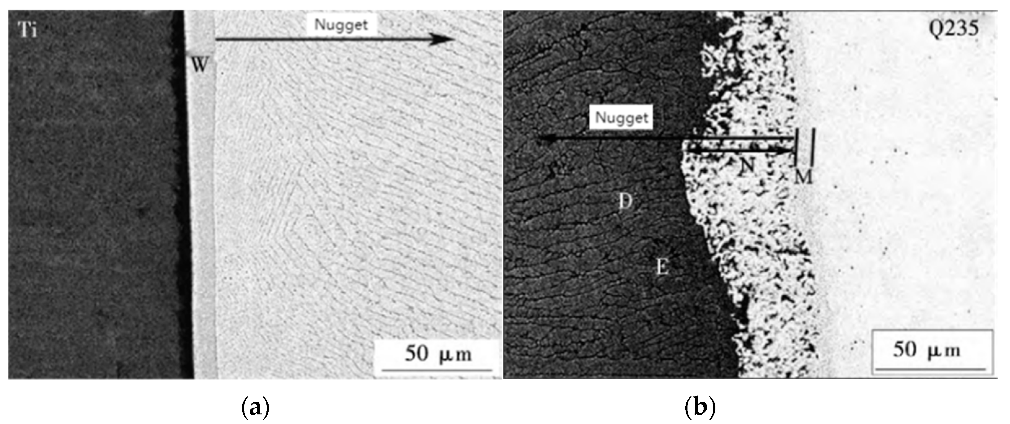
3.1. Interfacial Microstructure without Interlayers

During spot welding of titanium/steel, Fe–Ti intermetallic compounds with high brittleness and hardness are formed in welded joints [53]. The welded joint mainly consists of TiFe2+α-Fe eutectic structure near the steel side, TiFe columnar crystal and TiFe+α-Ti eutectic structure near the titanium side. As is shown in Figure 2a, the band TiFe+α-Ti with thickness of 12 μm and the columnar TiFe with thickness of 50 μm are observed near the titanium side. The microstructure near the steel side is shown in Figure 2b; the M layer near the Q235 steel is the supersaturated solid solution product of Ti element in Fe element with a thickness of about 6 μm, and the N layer is TiFe2+α-Fe with a thickness of 30–50 μm. The composition of the columnar crystal in the fusion zone is TiFe.
Liu et al. [54] observed an M layer with a thickness of 30–50 μm near the steel side, which is composed of TiFe2+α-Fe, and the columnar crystal structure of TiFe was formed near the core of the M layer. A layer of TiFe+α-Ti with a thickness of about 12 μm was observed near the titanium side, denoted as the N layer. The formation of a columnar crystal structure with a thickness of about 50 μm is found in the molten core near the N layer, and the columnar growth direction changes to the heat dissipation direction as shown in Figure 3.

3.2. Effects of Adding an Interlayer

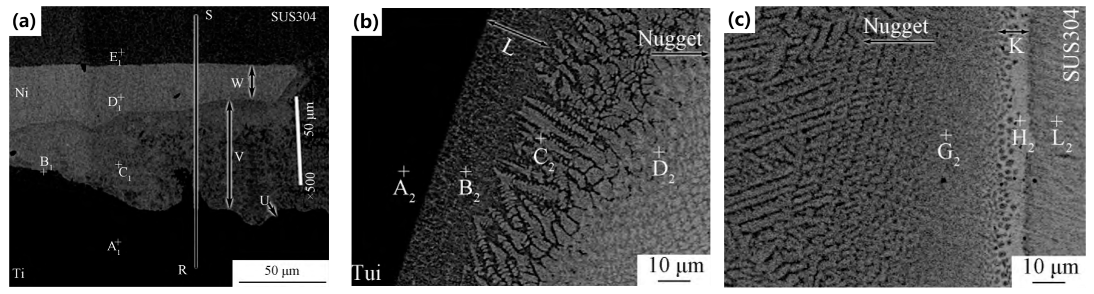
3.2.1. Ni Interlayer

When a Ni interlayer is added between 304 stainless steel and TC4 for spot welding, the Fe–Ti compound in the joint is replaced by a Ti–Ni compound with lower brittleness, which improves the performance of the joint [55]. The melted Ni is squeezed to the edge of the molten core, forming a thinner layer of α-Ti+Ti2Ni and a thicker layer of TiNi compounds [56]. In the welded joint close to the Ti plate, a layered structure of α-Ti+TiFe with a width of about 20 μm is formed, and the TiFe2+α-Fe layer is observed near SUS304 whose width is about 3 μm. The center of the welded joint is mainly composed of columnar TiFe and TiFe2 as shown in Figure 4.

3.2.2. Cu Interlayer

Fe–Ti intermetallic compounds are the main structures formed in the welded joint near both sides of the base material after adding a Cu interlayer [57]. The side near the titanium is composed of 15 μm thick TiFe and α-Ti, the composition near the steel side is TiFe2+α-Fe, with a thickness is 10 μm, and the center of the welded joint is mainly TiFe and TiFe2. The melted Cu foil is extruded to the edge of the molten core to form a CuTi2+CuTi region [58]. As shown in Figure 5, the movement of copper to both sides is inhibited after the Cu interlayer is fixed to the steel surface using an ultrasonic vibration device. Fe–Ti compounds were significantly reduced, which only formed a compound zone with thickness of 2 μm near the interface of Q235 side, and the core zone was mainly TiCu and TiCu2 [59].

3.2.3. Nb Interlayer

When Nb is used as the interlayer for RSW, the Nb layer in the welded joint does not completely disappear [60]. As shown in Figure 6, a dendrite layer with a thickness of about 20 μm was observed near the steel side and was denoted as the R layer, which was composed of solid solutions of Nb and Ti in Fe. The researchers found a serrated reactant layer with a thickness of about 15 μm near the Nb side, denoted as the S-layer, and composed mainly of FeNb. The center of the welded joint consists of α-Fe and a relatively small amount of Fe2Nb. There is a layer of about 50 μm thickness on the titanium side, referred to as the T layer, which is composed of Fe and Nb in the solid solution of Ti [54]. Zhang et al. [61] found 8 μm thick Fe2Nb+α-Fe and 14 μm thick Fe2Nb on the Nb/Q235 side, and detected a 25 μm thick compound layer on the Nb/Ti side, which is the supersaturated solid solution of Nb in Ti.

3.2.4. Ta Interlayer

In the spot welding of pure titanium and stainless steel SUS304 using Ta foil as the interlayer, Qiu et al. [62] found a light gray band Ⅰ zone near Ta with a thickness greater than 10 μm, which is the eutectic structure of FeTa+Ta; Region Ⅱ is about 1 μm of A Fe2Ta. A supersaturated solid solution Ⅲ region of Ta with a thickness of about 8 μm in α-Ti is observed in Ti near the Ta/Ti interface as shown in Figure 7.

3.2.5. Alloy Layers

When Ni–Cu alloy (Ni60%) is used in interlayer spot welding TC4/Q235, three layered regions are formed between the substrate as shown in Figure 8. From the side near TC4, Ti2Ni (17 μm thick), Ti2Ni + TiCu (15 μm thick) and TiNi + Cu3Ti2 + Fe2Ti (33 μm thick) are obtained [63].
Zhang et al. used BAg45CuZn as the interlayer for RSW of TC4/304SS, and added three different adsorption layer structures of V/Cr [64], V + Nb/Cr [65,66] and V + Mo/Cr + Mo [67] between the substrate and the interlayer, respectively. The experimental results show that Fe–Cr, Fe–Nb, Ti–V, Mo–V, Mo–Cr and other phases with low brittleness can replace part of the original Fe–Ti phase with the intervention of Cr, V, Nb and Mo elements to effectively improve the strength of the joint.

4. Effects of Interlayer on Defects in Titanium/Steel RSW Joints

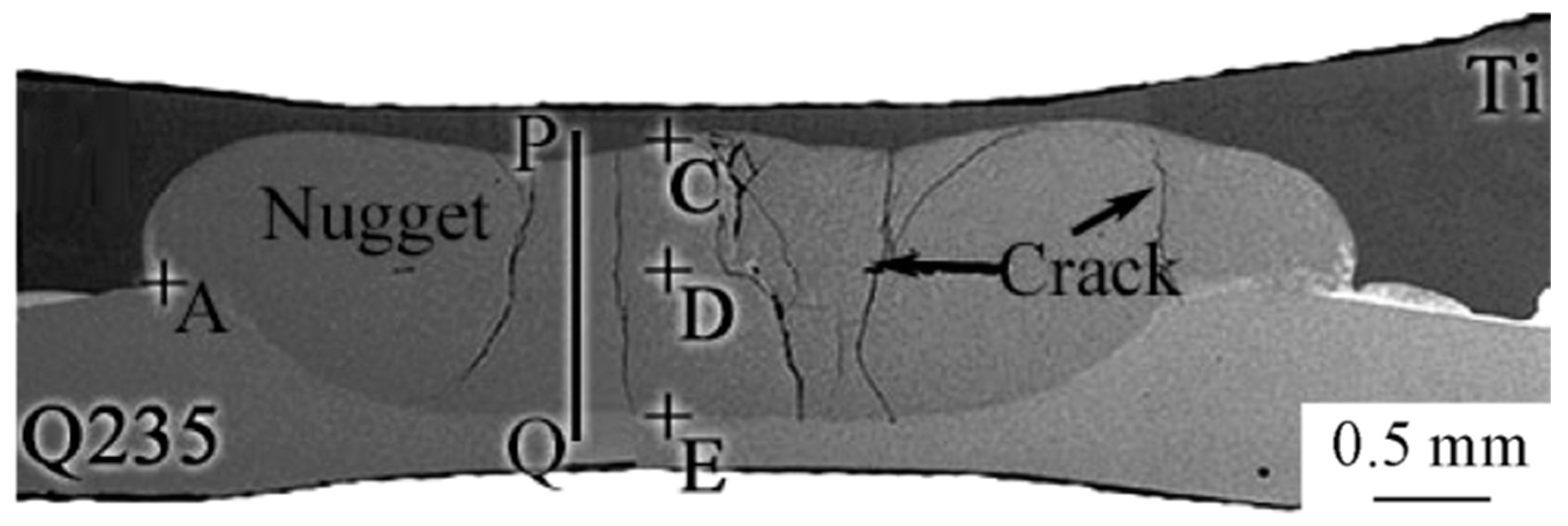
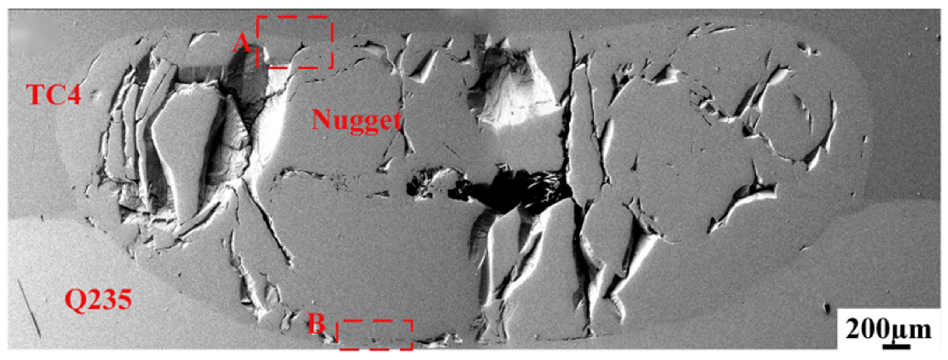
4.1. Defects in Ti–Steel Joints without Interlayer

When no interlayer is added, the microstructure of the spot welded joint of TC4/Q235 is shown in Figure 9, and it can be seen that the welded joint is full of macroscopic cracks and pores [63].During the solidification process, the metal in the molten pool is subjected to local stress and strain due to volume shrinkage, resulting in the metal in the molten pool being unable to fill the entire molten core after it solidifies; consequently, holes are formed in the molten core. Because the linear expansion coefficient of titanium is different from that of steel, the contraction rate of the two is different when the temperature is reduced. Therefore, a large amount of internal stress is generated in the welded joint, which aggravates the expansion of cracks and holes.

4.2. Influence of Adding Cu Interlayer on Defects in Ti–Steel Joints

Figure 10 shows the cracks in the welded joint that are approximately perpendicular to the bonding interface during spot welding with Cu as the interlayer [58]. This configuration occurs because the electrode pressure applied in the vertical direction of the base material counteracts the tensile stress of the molten metal in that direction, so the force acting on the molten metal is mainly parallel to the tensile stress of the interface direction. The larger the molten pool is, the greater is the tensile stress on molten metal during cooling and solidification, and the longer the duration of solid–liquid phase during solidification, resulting in more cracks in welded joint.

4.3. Influence of Adding Ni Interlayer on Defects in Ti–Steel Joints

The morphology of the welded joint after adding the Ni intermediate layer is shown in Figure 11, and SUS304 adjacent to the welded joint protrudes into the Ti plate to form a concave surface [56]. Because the thermal conductivity of SUS304 is greater than Ti, a large temperature gradient is formed along the plate direction during the welding process. The temperature field is characterized by the contraction of the higher isotherm towards the core, while the lower isotherm spreads out. As a result, SUS304 close to the welded joint has a large thermoplastic deformation under the action of electrode pressure to form a concave surface. In the direction perpendicular to the interface, the tension stress parallel to the bonding interface is the cause of the crack because the electrode pressure of the welded joint in the solidification stage cancels out the tension stress in this direction.

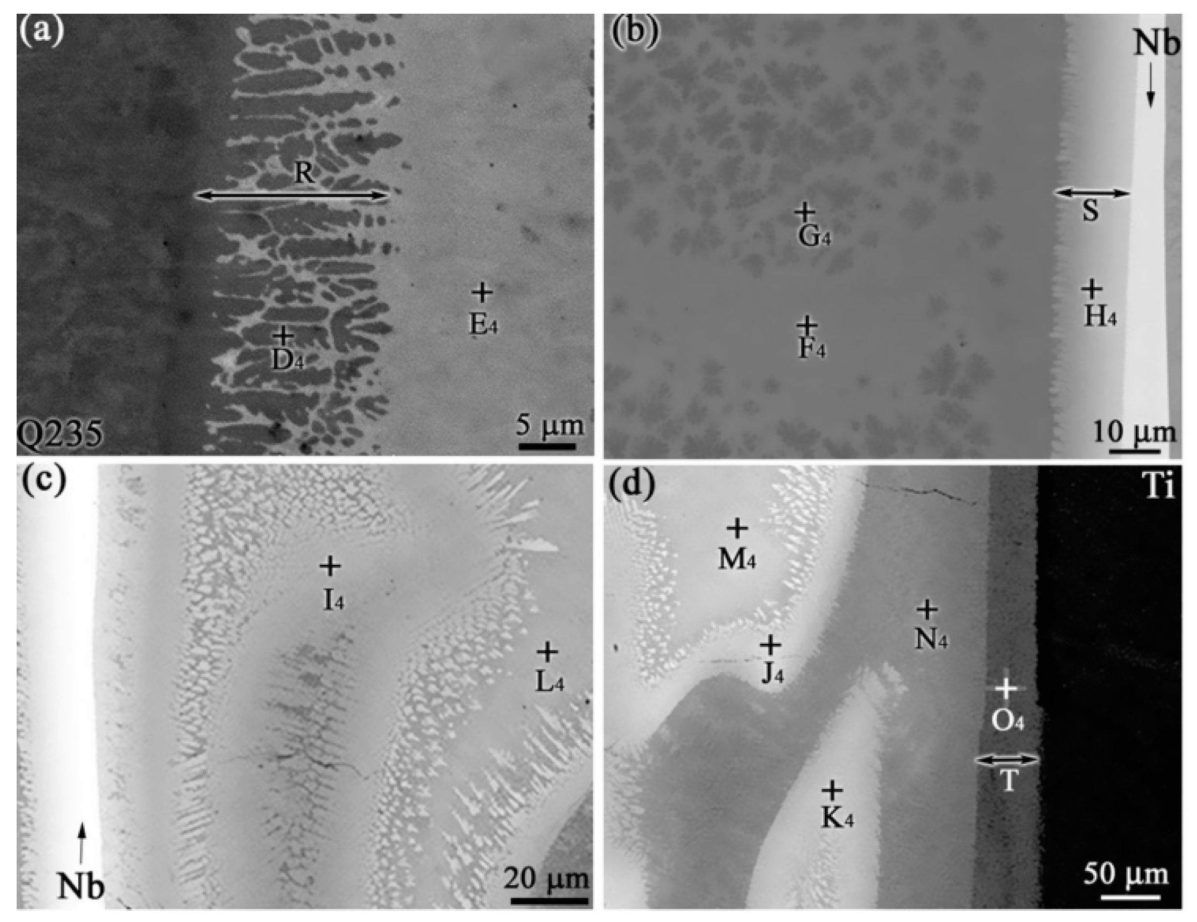
4.4. Influence of Adding Nb Interlayer on Defects in Ti–Steel Joints

Liu et al. [54] found some hole defects in Ti/Nb/Q235 joints, as shown in Figure 12. The solidification of molten pool metal occurs in the maintenance stage, which stops the electric heating and continues the pressure. At this time, the solid base metal around the molten metal has a binding effect on it, and the welded joint is cracked due to the stress. During the grinding process of the sample, the crack spreads to the region of the brittle intermetallic compound, which causes the metal to fall off from the crack to form long holes.

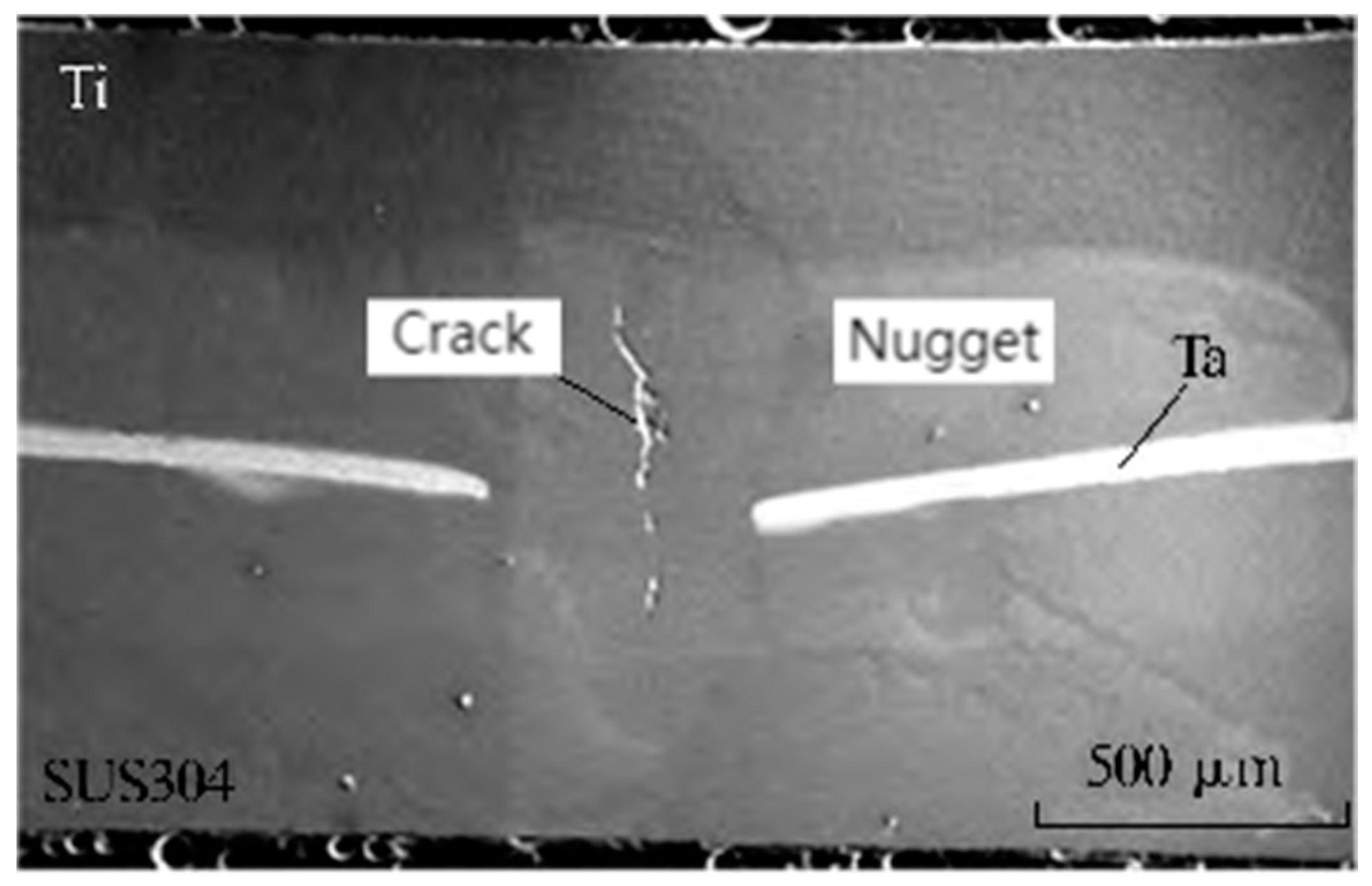
4.5. Influence of Adding Ta Interlayer on Defects in Ti-Steel Joints

Figure 13 shows part of the unfused interlayer metal in the welded joint and the crack perpendicular to the base material in the central region when Ta foil is used as the interlayer [62]. Because the coefficient of linear expansion of Ta is smaller than that of Ti and 304 stainless steel, and the center area of the welded joint is last solidified, there is no excess liquid metal to fill the central area after the edge metal solidifies, so it cracks under the action of tension.

5. Mechanical Properties

5.1. Influence of Process Parameters on Shear Strength of Joints

The shear load increases first and then decreases with increases in welding current, welding time and electrode pressure. With an increase in welding current or welding time, the heat generated by the joint increases, the molten metal increases, the diameter of the molten core increases, and the bearing area of the joint increases, so the shear strength of the joint increases. When the welding current is too large or the welding time is too long, splashing will occur in the joint, making the electrode indentation deep and reducing the joint performance. As the cooling time of the joint becomes longer, the columnar crystals continue to grow, resulting in the shear load of the joint decreasing [53].
With an increase in electrode pressure, the contact between the base material is more sufficient, which improves joint-forming. When the electrode pressure is too large, the molten metal moves towards the interface under the action of pressure to form a large number of brittle compounds along the outer edge of the molten core, which reduces the strength of the welded joint [58].

5.2. Influence of Interlayer Type on Shear Strength of Joints

Ta, Nb or V reacts with Ti to form solid solutions, and the brittleness of the intermetallic compounds formed by combining with Fe is lower than that of Fe–Ti intermetallic compounds. After using Nb as the interlayer in titanium/steel spot welding, the maximum shear load of the joint reaches 4.3 kN, which is 19.4% higher than that of 3.6 kN without adding interlayer [54]. Qiu et al. [62] added Ta foil in the middle of Ti and SUS304 stainless steel, and the welded joint shear resistance reached a maximum of 7.4 kN. When Nb is used as the interlayer material for micro-RSW, the shear load of the joint is increased from 0.9 kN to 1.24 kN, an increased of 38% [68]. When V + Mo/BAg45CuZn/Cr + Mo is used as the interlayer to weld TC4/304SS, the joint strength reaches a maximum of 235 MPa [64].
Cu, Ni or Cr reacts with Ti to form intermetallic compounds with low brittleness and high ductility, but forms only solid solutions with Fe. Under the optimal welding parameters, the maximum shear resistance of Ti/Ni/SUS304 welded joint can reach 5.62 kN [56]. When Cu is used as the interlayer material, the maximum shear load of the joint reaches 7.5 kN, which is 62.6% higher than that of 4.61 kN without the interlayer [59]. The various interlayers used by different researchers are tabulated in Table 1.

5.3. Influence of Interlayer Thickness on Shear Strength of Joints

The shear strength of the material increases first and then decreases with the increase in interlayer thickness. As the number of Nb interlayers increases, the shear strength of welded joints also increases first and then decreases [61]. When the thickness of the Nb layer is 300 μm, the joint shear load reaches a maximum of 6.29 kN. Zhang et al. [70] found that the shear strength of the joint increased first and then decreased with the increase in the thickness of the Cu foil, reaching a maximum of 324 MPa when the thickness was 0.4 mm. When a nickel interlayer was added by spraying and the thickness reached 27 μm, the shear strength reached 254.71 MPa [55].

5.4. Influence of Interlayer Type on Hardness of Joints

The joint hardness varies with the type of interlayer. The introduction of a Ni interlayer allows the more malleable Ni3Ti to replace Fe2Ti, resulting in a decrease in hardness to 500–600 Hv [68]; Yu et al. [59] found that the hardness of the welded joint with an added Cu interlayer decreased from 15.3 GPa to 7.9–9.1 GPa, due to Ti–Cu with lower hardness replacing Ti–Fe with higher hardness. At the same time, the internal stress of the welded joint is reduced, which is beneficial to the mechanical properties of the welded joint.

6. Summary and Outlook

This article reviews the influence of adding the interlayer on the macro defects, microstructure and mechanical properties of the joints in the titanium/steel resistance welding process. The following main conclusions can be drawn:
(1)
The fracture mode of titanium/steel RSW joints is a brittle fracture, and the fractured surface is mainly composed of FeTi, Fe2Ti and TiC.
(2)
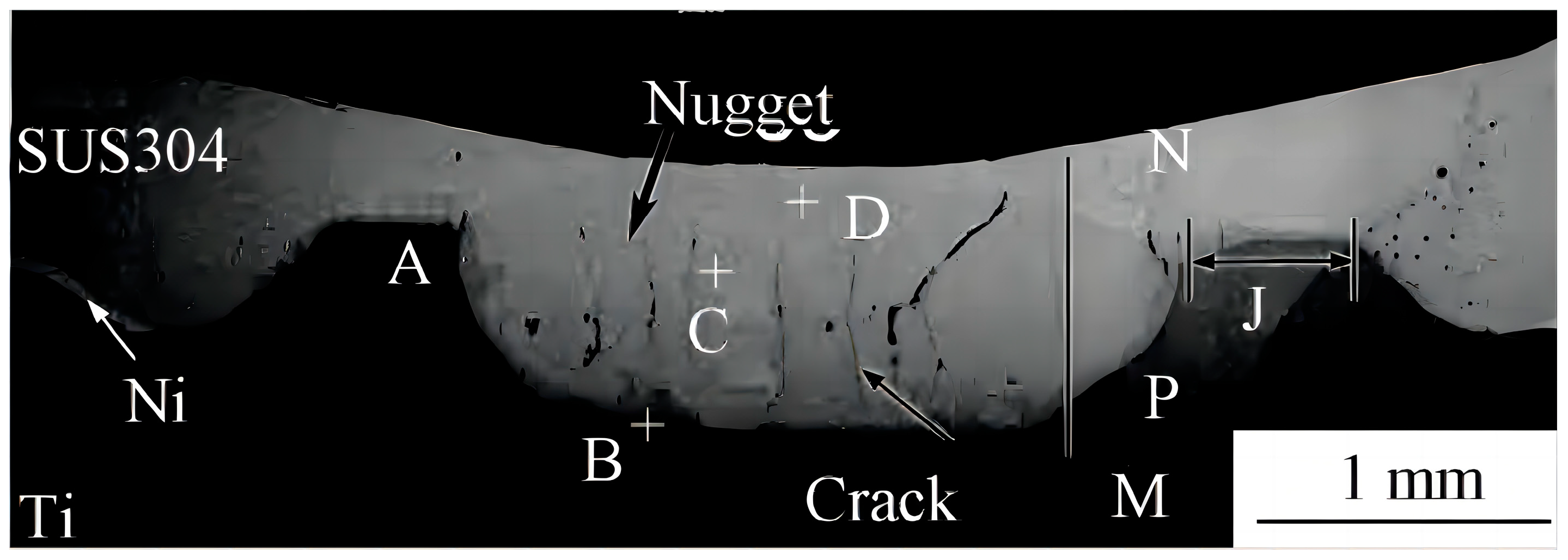
During the welding process, the molten pool undergoes volume contraction during solidification, resulting in local stress and strain due to the constraints of the surrounding solid metal. The solidified metal in the molten pool cannot completely fill the entire molten nugget, so defects such as holes and cracks are formed in the welded joint.
(3)
When the temperature decreases, the significant disparity in the coefficient of linear expansion between titanium and steel causes a significantly different rate of contraction, which leads to the generation of local stress and exacerbates the extension of defects. The excellent ductility of Cu, Ni and Ag can effectively alleviate the generation of internal stress and reduce the formation of defects.
(4)
Elements such as Cu, Ni, Cr, Nb, Ta and V can form solid solutions or intermetallic compounds with Fe or Ti, and the intermetallic compounds formed have lower brittleness than Fe–Ti compounds, thus increasing the joint strength.
(5)
By comparing the mechanical properties of joints in direct RSW of titanium/steel with those in titanium/steel RSW with the addition of interlayers, it is evident that the addition of Cu, Ni, Nb, Ta, 60% Ni–Cu alloy or BAg45CuZn layers results in a significant increase in shear strength of the joints. When Cu is used as the interlayer, the maximum shear load of the joint reaches 7.5 kN, which is 62.6% higher than that of 4.61 kN without the interlayer. The addition of a Ta interlayer makes the shear load reach 7.4 kN. By adding a Nb interlayer, the maximum shear load can reach 6.62 kN, and the shear strength of a Ni interlayer can reach 254.71 MPa by the spraying method. When V + Mo/BAg45CuZn/Cr + Mo is used as the interlayer to weld TC4/304SS, the maximum shear strength of the welded joint can reach 235 MPa.
At present, there are still some problems in the research of titanium/steel RSW. On the one hand, the interlayer of a single element is difficult to meet the needs of titanium/steel dissimilar metal welding. On the other hand, during welding, the melted interlayers are squeezed to the edge under the action of electric force in the spot-welding process, which leads to the failure of the interlayer.
In view of this, the future research directions of titanium/steel resistance welding are suggested to include the following aspects. Firstly, the influence of various interlayer elements on the interface bonding quality of titanium/steel dissimilar welds should be thoroughly researched, including the effects of various interlayer elements on intermetallic compound growth, defect formation and nugget size. Secondly, conducting research on the interface bonding mechanism and interface bonding performance of dissimilar titanium/steel welding using low-cost high-entropy alloys as interlayers is worthwhile. High-entropy alloys contain multiple alloying elements, allowing for the full utilization of the advantages and combined effects of various alloying elements, thereby achieving excellent performance in titanium steel welding joints. Finally, it is worthwhile to study the use of multi-element and multi-layer interlayers which could be more suitable for controlling the interfacial reactions on both the Ti–interlayer interface and the Fe–interlayer interface in titanium/steel dissimilar metal welds, while effectively controlling the spattering of molten intermediate layers, to achieve excellent Ti–Fe joint properties.

Author Contributions

Conceptualization, methodology, supervision, project administration, writing—review and editing, C.Z.; validation, formal analysis, investigation, data curation, writing—original draft preparation, visualization, Y.L. All authors have read and agreed to the published version of the manuscript.

Funding

The authors are grateful for the financial support from Innovation Group Project of Southern Marine Science and Engineering Guangdong Laboratory (Zhuhai) (No. 311021013). This work was also supported by the fund of State Key Laboratory of Clean and Efficient Turbomachinery Power Equipment, State Key Laboratory of Long-Life High Temperature Materials (No. DTCC28EE190933), National Natural Science Foundation of China, grant number 51605287, and the Natural Science Foundation of Shanghai, grant number 16ZR1417100.

Data Availability Statement

Not Applicable.

Conflicts of Interest

The authors declare no conflicts of interest.

References

  1. Liu, Y.; Zhang, Y.; Zhou, J.; Sun, D.; Li, H. Developing high-strength titanium/steel composite structures by adding composite interlayer. Mater. Lett. 2023, 350, 134961. [Google Scholar] [CrossRef]
  2. Ren, G.; Zhang, Y.; Zhou, J.; Sun, D.; Li, H. Titanium/steel composites were prepared by composite interlayer and two pass laser welding. J. Mater. Res. Technol. 2023, 27, 6367–6375. [Google Scholar] [CrossRef]
  3. Yang, X.; Guo, K.; Wang, Q.; Wang, Y.; Zhang, X.; Wang, Q.; Liu, R. Interfacial complex reactions and microstructures in vacuum hot-rolling bonded titanium-steel clad composites dominated by bonding temperature. Mater. Sci. Eng. A 2023, 885, 145621. [Google Scholar] [CrossRef]
  4. Ghalib, L.; Muhammad, A.K.; Mahdi, S.M. Study the Effect of Adding Titanium Powder on the Corrosion Behavior for Spot Welded Low Carbon Steel Sheets. J. Inorg. Organomet. Polym. Mater. 2021, 31, 2665–2671. [Google Scholar] [CrossRef]
  5. Xiao, X.; Hongxin, S.; Feng, Q.R.; Kexu, R.; Zhongren, L. Resistance spot welding process of aluminum alloy and low carbon steel composite electrode. J. Mater. Heat Treat. 2020, 41, 156–162. [Google Scholar]
  6. Wang, L.; Che, Y.; Wu, D.; Li, H.; Sun, D.; Zhang, X. Orthogonal Optimization of Resistance Spot Welding Parameters and Mi-crostructure and Mechanical Property of Aluminum Alloy/High Strength Steel Joint. Trans. Indian Inst. Met. 2021, 74, 1–9. [Google Scholar] [CrossRef]
  7. Li, J.; Schneiderman, B.; Gilbert, S.M.; Vivek, A.; Yu, Z.; Daehn, G. Process characteristics and interfacial microstructure in spot impact welding of titanium to stainless steel. J. Manuf. Process. 2020, 50, 421–429. [Google Scholar] [CrossRef]
  8. Dragan, A.M.; Zijah, B.; Damjan, K.; Miodrag, M.; Biljana, M.; Vladislav, K. Microstructure and Fatigue Properties of Resistance Element Welded Joints of DP500 Steel and AW 5754 H22 Aluminum Alloy. Crystals 2022, 12, 258. [Google Scholar] [CrossRef]
  9. Amirreza, M.; Mahdi, A. Friction spot brazing of stainless steel to titanium (grade 1) using aluminum foil. Mater. Res. Express 2022, 9, 056523. [Google Scholar]
  10. Fodorné, C.M.; Ákos, M. The Behaviour of Hybrid Aluminium-Steel Resistance Spot Welded Joints in Case of Dynamic Loading. Mater. Sci. Forum 2023, 6922, 97–104. [Google Scholar]
  11. Pan, B.; Sun, H.; Shang, S.L.; Banu, M.; Wang, P.C.; Carlson, B.E.; Lu, Z.-K.; Li, J. Understanding formation mechanisms of intermetallic compounds in dissimilar Al/steel joint processed by resistance spot welding. J. Manuf. Process. 2022, 83, 212–222. [Google Scholar] [CrossRef]
  12. Qian, C.; Ghassemi-Armaki, H.; Shi, L.; Kang, J.; Haselhuhn, A.S.; Carlson, B.E. Competing fracture modes in Al-steel resistance spot welded structures: Experimental evaluation and numerical prediction. Int. J. Impact Eng. 2024, 185, 104838. [Google Scholar] [CrossRef]
  13. Zhang, G.; Li, Y.; Lin, Z. Failure Mechanism of Al–Steel Resistance Spot Welding (RSW) Welds and a Metallic Bump Printed on Al Sheet-Assisted RSW (MBaRSW/Al) Welds During Lap-Shear Tests. Metall. Mater. Trans. A 2021, 52, 4922–4933. [Google Scholar] [CrossRef]
  14. Muhaed, A.; Alnaffakh, M.G. Characterization of AISI 316L Stainless Steel/Low Alloy Steel Resistance Spot Dissimilar Weld. Metallogr. Microstruct. Anal. 2023, 12, 622–633. [Google Scholar]
  15. Ion, M.; Călin, B.L.; Mircea, B.; Marius, C.C.; IonDragoș, U. Process parameters, structure and mechanical properties of dissimi-lar Nimonic 80 A/AISI 316 L resistance welded joints. Mater. Test. 2023, 65, 911–923. [Google Scholar]
  16. Shi, L.; Xue, J.; Kang, J.; Haselhuhn, A.S.; Ghassemi-Armaki, H.; Carlson, B.E. Fatigue behavior of three-sheet aluminum-steel dissimilar re-sistance spot welds for automotive applications. Procedia Struct. Integr. 2023, 51, 102–108. [Google Scholar] [CrossRef]
  17. Mingfeng, L.; Shanglu, Y.; Yanjun, W.; Wu, T. Joining aluminum to steel dissimilar metals using novel resistance spot welding process. Mater. Lett. 2022, 318, 132215. [Google Scholar]
  18. Xiang, C.; Daisuke, I.; Tanaka, S.; Li, X.J.; Bataev, I.A.; Hokamoto, K. Comparison of explosive welding of pure titanium/SUS 304 austenitic stainless steel and pure titanium/SUS 821L1 duplex stainless steel. Trans. Nonferrous Met. Soc. China 2021, 31, 2687–2702. [Google Scholar]
  19. Shanqing, H.; Haselhuhn, A.S.; Yunwu, M.; Zhuoran, L.; Lin, Q.; Yongbing, L.; Carlson, B.E.; Zhongqin, L. Effect of external magnetic field on resistance spot welding of aluminium to steel. Sci. Technol. Weld. Join. 2022, 27, 84–91. [Google Scholar]
  20. Yan, Z.; JianPing, Z.; DaQian, S.; HongMei, L. Three-pass laser welding of Ti alloy-stainless steel using Nb and Ni interlayers. J. Mater. Res. Technol. 2019, 9, 1780–1784. [Google Scholar]
  21. Cheepu, M.; Susila, P. Interface Microstructure Characteristics of Friction-Welded Joint of Titanium to Stainless Steel with Interlayer. Trans. Indian Inst. Met. 2020, 73, 1497–1501. [Google Scholar] [CrossRef]
  22. Bai, Y.-L.; Liu, X.-F. Interfacial reaction behavior of titanium/steel composite plate formed by cold-hot rolling. Mater. Charact. 2023, 202, 113030. [Google Scholar] [CrossRef]
  23. Bi, Z.; Li, X.; Wu, Y.; Xiong, S.; Wang, Q.; Rong, K. Interfacial bonding properties of titanium foil/steel explosive welding. J. Weld. Technol. 2022, 43, 81–85+118. [Google Scholar]
  24. Bin, L.; Peng, X.; Feng, Z.; Lei, Z.; Guoqing, P.; Jiangtao, W.; Kesshe, F. Research on interface structure of titani-um/steel composite plate. Equip. Manuf. Technol. 2023, 98–103. [Google Scholar]
  25. Zhao, B.; Jian, D.; Ma, L.; Ding, Y.; Zhou, L. Precipitation of intermetallic compounds in brazing of titanium and steel using brass filler. J. Am. Acad. Dermatol. 2020, 285, 116730. [Google Scholar] [CrossRef]
  26. Linlin, Y.; Bin, L.; Ran, W.; Yu, Q.; Lei, J.; Yuefeng, Q. Microstructure and properties of titanium/steel joints brazed by vacuum silver base brazing filler metal. Precious Met. 2017, 38, 1–6. [Google Scholar]
  27. Tong, W.; Chunli, Y. Interfacial evolution of titanium/steel clad plates during pulsed tungsten inert gas welding. Mater. Sci. Technol. 2023, 39, 834–846. [Google Scholar]
  28. Chatterjee, S.; Sahoo, S.K.; Swain, B.; Mahapatra, S.S.; Roy, T. Quality characterization of dissimilar laser welded joints of Ti6Al4V with AISI 304 by using copper deposition technique. Int. J. Adv. Manuf. Technol. 2020, 106, 4577–4591. [Google Scholar] [CrossRef]
  29. Qiaoling, C.; Qilu, C.; Min, Z.; Jianming, Z.; Pengkang, Z.; Fuxue, Y.; Peng, C.; Cheng, Y.; Hailong, L. Microstructure and mechanical properties investigation of explosively welded titanium/copper/steel trimetallic plate. Mater. Charact. 2022, 192, 112250. [Google Scholar]
  30. Xuejiao, L.; Zhixiong, B.; Quan, W.; Kai, R.; Mengben, X.; Tingzhao, Z.; Jingye, Q. Influence of copper foil interlayer on micro-structure and bonding properties of titanium-steel explosive welded composite plate. Mater. Today Commun. 2023, 34, 105143. [Google Scholar]
  31. Trykov, Y.; Gurevich, L.; Pronichev, D.; Trunov, M. Investigation of the rupture of Ti/Steel laminated composite with soft interlayers. FME Trans. 2016, 44, 16–21. [Google Scholar] [CrossRef]
  32. Angshuman, C.; Gopinath, M.; Sagar, S.; Vikranth, R.; Kumar, N.A. Mitigation of cracks in laser welding of titanium and stain-less steel by in-situ nickel interlayer deposition. J. Mater. Process. Tech. 2022, 300, 117403. [Google Scholar]
  33. Yu, M.; Xiaoyan, G.; Meng, C.; Xiaopeng, G.; Xiaohui, Z. Laser assisted diffusion bonding of TC4 titanium alloy to 301 stainless steel using a Ni interlayer. J. Mater. Res. Technol. 2022, 21, 739–748. [Google Scholar]
  34. Mohammad, A.; Prasad, R.K.; Khalid, R.H.; Murty, B.S.; Chandra, D.H.; Bhaduri, A.K. Friction Welding of Titanium to 304L Stainless Steel Using Inter-layers. Pract. Metallogr. 2011, 48, 188–207. [Google Scholar]
  35. Chu, Q.; Zhang, M.; Li, J.; Yan, C.; Qin, Z. Influence of vanadium filler on the properties of titanium and steel TIG welded joints. J. Mater. Process. Tech 2016, 240, 293–304. [Google Scholar] [CrossRef]
  36. Jianxiong, L.; Anupam, V.; Glenn, D. Improved properties and thermal stability of a titanium-stainless steel solid-state weld with a niobium interlayer. J. Mater. Sci. Technol. 2021, 79, 191–204. [Google Scholar]
  37. Yan, Z.; JianPing, Z.; DaQian, S.; XiaoYan, G. Characterization of Pulsed Laser Welded Titanium Alloy and Stainless Steel Joint Using Nb as Interlayer. Steel Res. Int. 2021, 92, 2000635. [Google Scholar]
  38. Lin, J.-Y.; Nambu, S.; Liu, M.; Koseki, T. Influence of Al and Ni interlayers on interfacial strength evolution during ultrasonic welding of ultra-low-carbon steel and pure Ti. Mater. Sci. Eng. A 2020, 798, 140073. [Google Scholar] [CrossRef]
  39. Cheepu, M.; Che, W.S. Friction Welding of Titanium to Stainless Steel Using Al Interlayer. Trans. Indian Inst. Met. 2019, 72, 1563–1568. [Google Scholar] [CrossRef]
  40. Taufiqurrahman, I.; Lenggo Ginta, T.; Mustapha, M. The effect of holding time on dissimilar resistance spot welding of stain-less steel 316L and Ti6Al4V titanium alloy with aluminum interlayer. Mater. Today Proc. 2021, 46, 1563–1568. [Google Scholar] [CrossRef]
  41. Nannan, W.; Ranfeng, Q.; Hongxin, S.; Keke, Z. Characteristics of interlayer resistance spot welding joints between aluminum alloy and low carbon steel. J. Mater. Heat Treat. 2015, 36, 70–74. [Google Scholar]
  42. Kang, Z.; Baokai, R.; Wenxiao, Y. Optimized designing of generalized electrodes for aluminum/steel resistance spot welding process based on numerical calculation. J. Manuf. Process. 2023, 99, 563–580. [Google Scholar]
  43. Gopinath, B.K. Multi-objective optimisation of friction welding parameters in joining titanium alloy and stainless steel with a novel interlayer geometry. Adv. Mater. Process. Technol. 2020, 6, 25–39. [Google Scholar]
  44. Han, K.; Wang, T.; Chang, S.; Tang, Q.; Zhang, B. Interface characteristics and mechanical property of titanium/steel joint by electron beam brazing with 72Ag-28Cu filler metal. J. Manuf. Process. 2020, 59, 58–67. [Google Scholar] [CrossRef]
  45. Kumar, S.A.; Gandhinathan, R. Optimization of process parameters for titanium alloy to itself and stainless steel brazed joints using BAg22 filler metal. Mater. Today Proc. 2020, 46, 9454–9461. [Google Scholar] [CrossRef]
  46. Li, A.H.; Li, T.; Chen, X.G.; Guo, W.B.; Xue, H.T.; Chen, C.X. Effect of copper interlayer to the microstructure and strength of alumina/304 stainless steel joint brazed with silver-copper-titanium filler. Mater. Werkst. 2023, 54, 1717–1727. [Google Scholar] [CrossRef]
  47. Wiegand, M.; Kimm, A.; Sommer, N.; Marks, L.; Kahlmeyer, M.; Böhm, S. Dissimilar Laser Beam Welding of Titanium to Stain-less Steel Using Pure Niobium as Filler Material in Lap Joint Configuration. Photonics 2023, 10, 1063. [Google Scholar] [CrossRef]
  48. Xiaohu, H.; Honggang, D.; Fengyun, Y.; Peng, L.; Zhonglin, Y. Arc welding of titanium alloy to stainless steel with Cu foil as interlayer and Ni-based alloy as filler metal. J. Mater. Res. Technol. 2021, 13, 48–60. [Google Scholar]
  49. Xiaohu, H.; Xinlong, W.; Shuhua, L.; Zeqin, C.; Wenxian, W.; Honggang, D.; Weiguo, L. Joining mechanism evolution of fusion welded TC4 titanium alloy/304 stainless steel dissimilar joint by GTAW. Sci. Technol. Weld. Join. 2023, 28, 1031–1040. [Google Scholar]
  50. YuanBo, B.; Yan, Z.; Kai, L.; Yan, X.; RuiLei, X. Two pass laser welding of 304 stainless to TC4 titanium alloy using monel 400/Nb bilayer. J. Mater. Res. Technol. 2020, 9, 16522–16528. [Google Scholar]
  51. Mansor, M.S.M.; Yusof, F.; Ariga, T.; Miyashita, Y. Microstructure and mechanical properties of micro-resistance spot welding between stainless steel 316L and Ti-6Al-4V. Int. J. Adv. Manuf. Technol. 2018, 96, 2567–2581. [Google Scholar] [CrossRef]
  52. Zhang, Y.; Chen, Y.; Zhou, J.; Sun, D.; Li, H. Microstructure and mechanical property in laser welding-brazing of stainless steel and titanium alloy using 63Sn-37Pb alloy as filler metal. Weld. World 2019, 64, 257–266. [Google Scholar] [CrossRef]
  53. Ranfeng, Q.; Qing-Zhe, L.; Hong-Xin, S.; Zhong-Ren, L. Resistance spot welding of titanium and low carbon steel. J. Weld. Technol. 2018, 39, 45–48+131. [Google Scholar]
  54. Liu, C.; Zhang, J.; Shi, H.; Li, Q. Influence of Interlayer Nb on the Performance of Joint Between Titanium and Steel Welded by Resistance Spot Welding. J. Mater. Eng. Perform. 2021, 31, 1155–1162. [Google Scholar] [CrossRef]
  55. Zhang, P.; Yu, H.; Wang, G. Joint formation mechanism of titanium/steel resistance brazing under nickel coating. J. Weld. Sci. 2017, 38, 62–66+131–132. [Google Scholar]
  56. Li, D.; Qiu, R.; Ren, K.; Shi, H. Resistance spot welding of titanium and stainless steel based on Ni interlayer. Trans. Mater. Heat Treat. 2018, 39, 131–137. [Google Scholar]
  57. Li, Q.-Z. Research on Interlayer Resistance Spot Welding between Titanium and Low Carbon Steel. Master’s Thesis, Henan University of Science and Technology, Luoyang, China, 2017. Available online: https://kns.cnki.net/kcms2/article/abstract?v=eoCTaIZmBOOuyODzzGd77TO0_jP6rKzNxL3lAxRLtdy0O_pyyoHK7lxHhQqtV6GNktIsfVh1JHvumYBc8i_ZhPaJ8WxFUT0JhZn6NFo1HIz9VqfkGuY3kxfeNuSViVpRR-n-9pM5hGqv6bROQLypzg==&uniplatform=NZKPT&language=CHS (accessed on 1 March 2024).
  58. Hongxin, S.; Zhao, J.; Li, Q.; Qiu, R. Characteristics of copper resistance spot welding joint between titanium and low carbon steel. Trans. Mater. Heat Treat. 2021, 42, 180–186. [Google Scholar]
  59. Yu, J.; Zhang, H.; Wang, B.; Du, R.; Fan, Y.; He, P. Interfacial evolution behavior and mechanical properties of Ti/steel joint via ultrasonic seam assisted resistance spot welding with Cu interlayer. J. Manuf. Process. 2023, 95, 535–550. [Google Scholar] [CrossRef]
  60. Qiu, R.; Li, Q.; Zhao, Y.; Shi, H. Resistance spot welding of titanium and low carbon steel with niobium as the interlayer. Rare Met. Mater. Eng. 2019, 48, 33309–33314. [Google Scholar]
  61. Zhang, K.; Wang, N.; Wang, Q.; Yan, B.; Qiu, R. Effect of niobium interlayer on microstructure and properties of titanium and Q235 low carbon steel resistance spot welding joint. J. Mater. Heat Treat. 2023, 44, 191–198. [Google Scholar]
  62. Qiu, R.; Hou, L.; Li, D.; Shi, H.; Guo, J. Resistance spot welding of titanium and stainless steel based on Ta interlayer. Weld. Mach. 2016, 46, 13–16. [Google Scholar]
  63. Yu, J.; Zhang, H.; Wang, B.; Gao, C.; Sun, Z.; He, P. Dissimilar metal joining of Q235 mild steel to Ti6Al4V via resistance spot welding with Ni–Cu interlayer. J. Mater. Res. Technol. 2021, 15, 4086–4101. [Google Scholar] [CrossRef]
  64. Zhang, P.; Wang, G.; Li, S. Effect of Cr and V powder layer on microstructure and properties of titanium/steel resistance brazing joints. J. Lanzhou Univ. Technol. 2017, 43, 24–28. [Google Scholar]
  65. Pengxian, Z.; Zhizhong, F.; Shilong, L. Microstructure and Interfacial Reactions of Resistance Brazed Lap Joints between TC4 Titanium Alloy and 304 Stainless Steel Using Metal Powder Interlayers. Materials 2021, 14, 180. [Google Scholar] [CrossRef]
  66. Zhang, P.; Li, S. Research on resistance brazing of titanium/steel with chromium, niobium and vanadium metal powder as interlayer. Hot Work. Technol. 2018, 47, 53–56. [Google Scholar]
  67. Zhang, P.; Qiao, Y. A composite transition metal sheet for titanium/steel resistance brazing joint. Hot Work. Technol. 2020, 49, 136–141. [Google Scholar]
  68. Zhang, K.; Shamsolhodaei, A.; Ghatei-Kalashami, A.; Oliveira, J.P.; Zang, C.; Schell, N.; Li, J.; Midawi, A.R.H.; Lopes, J.G.; Yan, J.; et al. Revealing microstructural evolution and mechanical properties of re-sistance spot welded NiTi-stainless steel with Ni or Nb interlayer. J. Mater. Sci. Technol. 2024, 180, 160–173. [Google Scholar] [CrossRef]
  69. Zhang, P.; Lu, J.; Chen, P. Effect of copper foil type and thickness on microstructure and properties of titani-um/steel resistance spot welding joint. Mech. Eng. Mater. 2021, 45, 46–51. [Google Scholar] [CrossRef]
  70. Ren, K.; Ma, H.; Li, D. Qiu Ranfeng, Shi Hongxin, Nb layer resistance spot welding of titanium and stainless steel. J. Mater. Heat Treat. 2019, 40, 181–186. [Google Scholar]
Figure 2. SEM images of Ti/Q235 joint (a) near the Ti side (b) near the Q235 side—Reprinted from Ref. [53]. 2018 Journal of Welding Technology.
Metals 14 00429 g002
Figure 3. SEM images of the Ti/Q235 joint (a) near the Q235 side and (b) near the Ti side—Reprinted from Ref. [54]. 2021 Springer.
Metals 14 00429 g003
Figure 4. SEM images of Ti/Ni/SUS304 joint (a) at the molten core left end, (b) near the Ti side and (c) near the SUS304 side—Reprinted from Ref. [56]. 2018 Transactions of Materials and Heat Treatment.
Metals 14 00429 g004
Figure 5. SEM images of TC4/Cu/Q235 joint: (a) overview, (b) near the Ti side, (c) central area and (d) near the Q235 side—Reprinted from Ref. [59]. 2023 Elsevier.
Metals 14 00429 g005
Figure 6. SEM images of Ti/Nb/Q235 joint (a) near the Q235 side, (b) Nb-Q235, (c) Nb–Ti and (d) near the Ti side—Reprinted from Ref. [54]. 2021 Springer.
Metals 14 00429 g006
Figure 7. SEM images of Ti/Ta/SUS304 joint (a) near the SUS304 side and (b) near the Ti side—Reprinted from Ref. [62]. 2016 Welding Machine.
Metals 14 00429 g007
Figure 8. SEM image of TC4/Ni-Cu alloy/Q235 joint—Reprinted from Ref. [63].
Metals 14 00429 g008
Figure 9. Morphology of TC4/Q235 spot welding joint—Reprinted from Ref. [63].
Metals 14 00429 g009
Figure 10. Morphology of Ti/Cu/Q235 spot welding joint—Reprinted from Ref. [58]. 2021 Transactions of Materials and Heat Treatment.
Metals 14 00429 g010
Figure 11. Morphology of Ti/Ni/SUS304 spot welding joint—Reprinted from Ref. [56]. 2018 Transactions of Materials and Heat Treatment.
Metals 14 00429 g011
Figure 12. Morphology of Ti/Nb/Q235 spot welding joint—Reprinted from Ref. [54]. 2021 Springer.
Metals 14 00429 g012
Figure 13. Morphology of Ti/Ta/SUS304 spot welding joint—Reprinted from Ref. [62]. 2016 Welding Machine.
Metals 14 00429 g013
Table 1. Summary of the types of interlayers used by researchers in the titanium/steel spot welding process.
Base Materials to Be WeldedType of Interlayer UsedInterlayer ThicknessIntermetallic CompoundJoint HardnessShearing StrengthReference
Ti/Q235//FeTi, Fe2Ti/2.85 kN[53]
Ti/Q235Cu100 μmCuTi2, CuTi/4.4 kN[57]
Ti/Q235Cu100 μmCu–Ti/4.2 kN[58]
TC4/Q235Cu150 μmCuTi2, CuTi7.9–9.1 GPa7.5 kN[59]
Ti/SUS304Ta110 μmFe2Ta, FeTa/7.4 kN[62]
Ti/Q235Nb100 μmFeNb, FeNb2/4.3 kN[54]
NiTi/316LNb100 μmNiTi, Fe7Nb6500–600 Hv1.2 kN[68]
Ti/SUS304Nb100 μmNiTi/6.62 kN[69]
Ti/SUS304Ni100 μmTi2Ni, TiNi/5.62 kN[56]
TC4/304SSNi27 μmNiTi, NiTi2/254.71 MPa[55]
TC4/304SSV/BAg45CuZn/Cr200 μmTi–V, Cr–Fe/187 MPa[64]
TC4/304SSV + Nb/BAg45CuZn/Cr200 μmTi–V, Ti–Nb, Cr–Fe/226 MPa[66]
TC4/304SSV + Mo/BAg45CuZn/Cr + Mo200 μmTi–V, Cr–Fe, Mo–V, Mo–Cr/235 MPa[67]
Disclaimer/Publisher’s Note: The statements, opinions and data contained in all publications are solely those of the individual author(s) and contributor(s) and not of MDPI and/or the editor(s). MDPI and/or the editor(s) disclaim responsibility for any injury to people or property resulting from any ideas, methods, instructions or products referred to in the content.

