1. Introduction
In terms of manufacturing processes, the Ni-based superalloy Inconel 718 has typically been developed using conventional methods such as casting, forging, and powder metallurgy, resulting in excellent mechanical properties [
1,
2]. However, due to the slow cooling rate during solidification, the cast components have a coarse grain size, dendritic segregation, and solidification defects, which lead to a degradation in mechanical properties. Fabricating Inconel 718 components at room temperature using conventional machining methods is challenging due to its high shear strength and low material removal rate. With rapid advances in technology, including those in the aircraft and nuclear industries, many Inconel 718 components now need to meet the demands of industry, exhibiting highly complex part geometries, particularly complex internal geometries, with precise dimensional tolerances and improved mechanical properties. Therefore, it is crucial to develop innovative manufacturing techniques to produce Inconel 718 parts with complex configurations and high performance.
L-PBF (Laser-Powder Bed Fusion), also known as SLM (Selective Laser Melting), is one of the most promising metal additive manufacturing (AM) technologies, offering several advantages over traditional techniques [
3]. These include the reduction of production steps, high flexibility, low material consumption, and, most importantly, the possibility to manufacture parts with high geometrical complexity and dimensional accuracy [
4,
5,
6,
7]. Numerous researchers are actively engaged in comparative studies between conventionally manufactured Inconel 718, using methods such as casting and forging, and components produced through the SLM process. Trosch et al. [
8] and Zhao et al. [
9] reported that the SLM process, used in the production of Inconel 718 components, provides geometric flexibility in additive manufacturing and exhibits static mechanical properties that are at least as superior as those of traditional forging or casting materials.
Generally, the characteristics of parts produced through SLM are mainly influenced by key parameters of the SLM process, including laser power, scanning speed, and build orientation [
10]. Several studies have been conducted to minimize defects and improve the mechanical properties of additively manufactured Inconel 718. Researchers have investigated different variables in order to optimize the production process for this purpose. Choi et al. [
11] reported that the scanning speed of SLM process significantly influenced the structure and mechanical properties of Inconel 718 components. Pan et al. [
12] investigated the microstructure and tensile properties of Inconel 718 using only scan speed as a variable in the SLM process, with two different settings (P1: 900 mm/s, P2: 1300 mm/s). The volumetric energy density of the specimens scanned at a higher speed was higher than that of the specimens scanned at a lower speed. It was reported that the orientation of the microstructure changes in accordance with the building direction, leading to corresponding alterations in tensile properties and ductility. However, there are few studies that have analyzed in detail the room temperature and high-temperature tensile properties, as well as fracture mechanisms, with different building directions in the SLM process. In order to enhance the tensile properties at both room and high temperatures, heat treatment is essential to achieve the desired microstructure and properties of Inconel 718 alloy components produced through additive manufacturing. An important strengthening mechanism in the Inconel 718 alloy involves cohesive strengthening through the metastable γ′ phase and anti-phase boundary (APB) strengthening [
13]. Sui et al. [
14] studied the effect of solution holding time on γ″ phase and found that higher volume of γ″ phase can improve the yield strength. However, the presence of depleted γ″ refers to the loss of hardenability, which is associated with increased susceptibility to high-temperature cracking [
15]. Some researchers have reported that the formation and distribution of the δ phase are also crucial factors in determining the high-temperature performance of Inconel 718 [
16]. Deng et al. [
17] reported that the precipitation of the δ phase decreases the yield and tensile strength of the alloy. However, they also noted that the fracture toughness and ductility could increase to some extent when there is no region around the δ phase where the γ″ phase is absent. Strößner et al. [
18] investigated the impact of two heat treatment processes (HT1: solutionizing treatment, double aging treatment/HT2: homogenization treatment, solutionizing treatment, double aging treatment) on the mechanical properties of Inconel 718 alloy manufactured by SLM. According to the results, the LPBF IN718 treated with HT1 at 650 °C exhibited higher tensile strength and hardness compared to HT2, but the elongation to failure was lower. The reason for this is that in the case of “HT 1”, the formation of intragranular δ-phase is observed due to niobium micro-segregations. Zhang et al. [
19] conducted a quantitative analysis of the strengthening mechanism of Inconel 718 alloy fabricated by SLM under as-built, direct aging (DA), and homogenization + aging (HA) conditions. The Laves phase contributes approximately 100–110 MPa to the yield strength. The γ″ and γ′ strengthening contribute 590–600 MPa and 830–850 MPa to the strength increment of the DA and HA specimens, respectively. The direction of building and the heat treatment of the SLMed part have a significant impact on the microstructure and mechanical properties. Therefore, it is necessary to thoroughly consider the effect of the building direction and post-heat treatment of Inconel 718 on its microstructure, room temperature, and high-temperature characteristics.
Inconel 718 is widely used in various high-temperature applications because of its capability to retain high mechanical strength up to 650 °C and its resistance to surface degradation in corrosive environments. Therefore, in this study, tensile tests were conducted at room temperature and 650 °C [
20]. The present manuscript will focus on the microstructure, tensile strength, and fracture mechanism of Inconel 718 with respect to building direction and heat treatment. An in-depth microstructural analysis was conducted on as-built (AB), homogenization + solution + aging (HSA), homogenization + aging (HA), and solution + aging (SA) specimens with varying building directions (vertical and horizontal). Microhardness and tensile tests were conducted to assess the influence of these different microstructures on mechanical properties. The results are discussed in two main aspects: (1) the effect of the build direction on the tensile behavior and fracture mechanism of the SLM parts, and (2) a comparison between the post-heat-treated specimens and the as-built specimens with the same build orientation.
2. Experimental Procedure
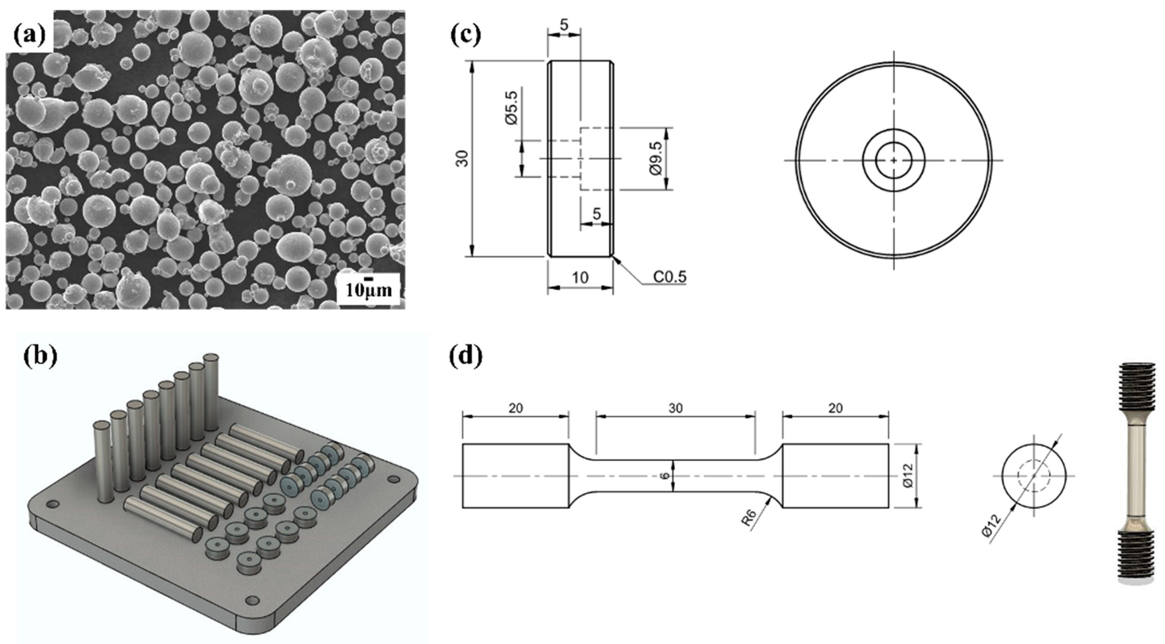
In this study, gas-atomized Inconel 718 superalloy powder with particle sizes ranging from 15 to 45 μm was used as a new powder for Selective Laser Melting (SLM). The morphology and particle distribution are depicted in
Figure 1a, showing that the powder was predominantly spherical. The chemical composition (wt.%) is as follows: [50.60] Ni, [18.40] Cr, [4.80] Nb, [2.93] Mo, [0.96] Ti, [0.54] Al, [0.040] Co, [0.046] Mn, [0.078] Si, and [0.042] C, with the remaining balance being Fe. Tensile specimens and analysis specimens (30 mm in diameter, 10 mm in height) were fabricated in two orientations, horizontal and vertical, to compare their mechanical properties along the gradient of the build direction.
Figure 1b–d illustrates schematics of the analysis specimens and tensile specimens. The tensile specimens, as depicted in
Figure 2b, were machined into rods (diameter 13 mm, height 10 mm) after printing and were subsequently subjected to helical machining while maintaining the specifications of ASTM E8 specimen 3. The specimens were modeled into 3D shapes using Fusion 360, followed by the creation of supports using Materalise Magics software version 25.01. Subsequently, they were manufactured using Concept Laser M1 equipment at the Converging Materials Core Facility of Dong-Eui University, following the specifications outlined in
Table 1. Continuous and parallel scanning share the advantage of being the easiest to generate from a CAD file using the same laser pattern [
21].
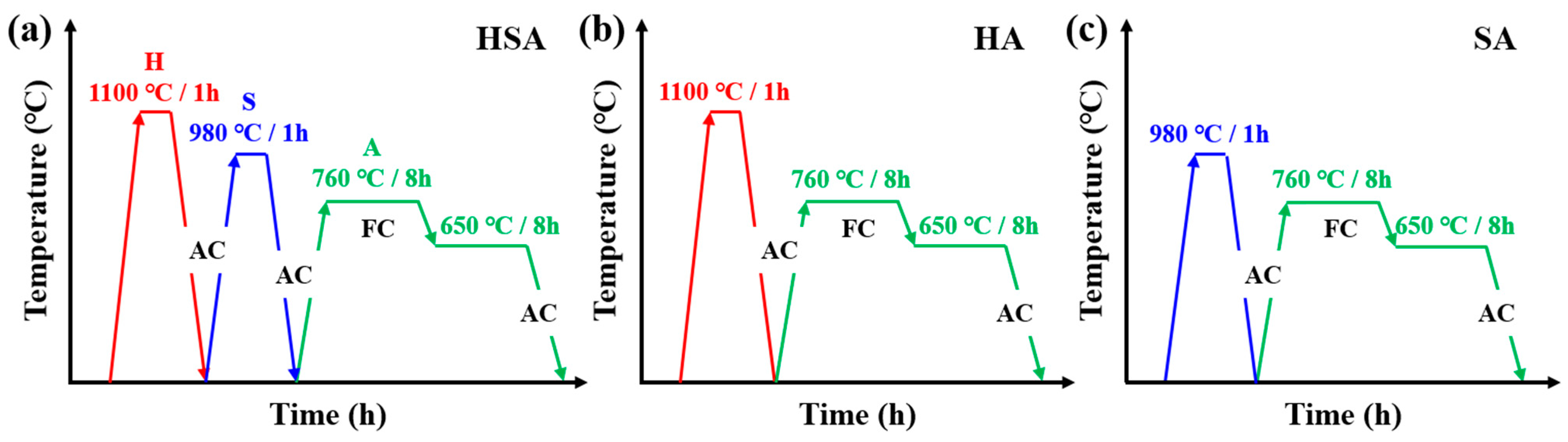
To investigate the impact of selective laser melting (SLM) build orientation and heat treatment on the microstructure and tensile properties of SLMed Inconel 718, three heat treatment conditions, as depicted in
Figure 2, were established, considering the time-temperature-transformation (TTT) curve of Inconel 718. The details of notation for specimen heat treatment are listed in
Table 2. The double aging treatment listed in all cases was 760 °C (8 h) followed by furnace cooling, then 650 °C (8 h) followed by air cooling temperature. The homogenization treatment and solution treatments involved holding at 1100 °C for 1 h and holding at 980 °C for 1 h followed by air cooling, respectively. The homogenization treatment was conducted at 1100 °C for 1 h, while the solution treatment (S) involved holding at 980 °C for 1 h, followed by air cooling. Aging treatment (A) for precipitation hardening involved two consecutive stages to precipitate strengthening phases (γ′ and γ″). This was carried out by holding at 760 °C for 8 h, followed by air cooling at 650 °C for 8 h. In nickel-based superalloys, secondary aging after primary aging forms finer precipitates, enhancing high-temperature strength. Therefore, four heat-treated specimens were prepared: AB, HSA, HA, and SA. The AB specimen is as-built specimen without any heat treatment. The HSA specimen was crafted from an as-built sample, undergoing homogenization treatment at 1100 °C for 1 h with air cooling (AC). Subsequently, it underwent solution treatment at 980 °C for 1 h with air cooling (AC), followed by a double aging process: first at 760 °C for 8 h with furnace cooling (FC), and then at 650 °C for 8 h with air cooling (AC). HA and SA specimens were also heat-treated using a specific heat treatment combination. The horizontally-built/vertically-built AB, HSA, HA, and SA samples were designated as H-AB/V-AB, H-HSA/V-HSA, H-HA/V-HA, and H-SA/V-SA, respectively.
The microstructure was examined using optical microscopy (ECLIPSE LV150L, Nilkon, Tokyo, Japan), field-emission scanning electron microscopes ((FE-SEM, Quanta 200 FEG, FEI Company, Amsterdam, The Netherlands), and a Vickers hardness tester (HM-210, Mitutoyo, Tokyo, Japan). For the microstructure measurements, specimens were electropolished for 6 s at 4 volts in a 4% oxalic acid and hydrogen oxide solution. To facilitate high-temperature tensile testing, specimens were fabricated in accordance with ASTM E8 standards. Initially, they were produced in rod form and subsequently underwent thread machining to conform to the dimensions specified for tensile test specimens with a gauge length of 30 mm and a gauge diameter of 6 mm. All the specimens were tested at an elevated temperature of 650 °C using INSTRON 5982 tensile testing machine (Instron, Norwood, MA, USA). Individual series contained three specimens, and the final results were obtained based on their average values. The room temperature tensile tests were conducted using an INSTRON 5585H (Instron, Norwood, MA, USA) with a two-step strain with an elastic region (0.2% offset) set at 0.005 mm/min and 0.05 mm/min, respectively.
3. Results and Discussion
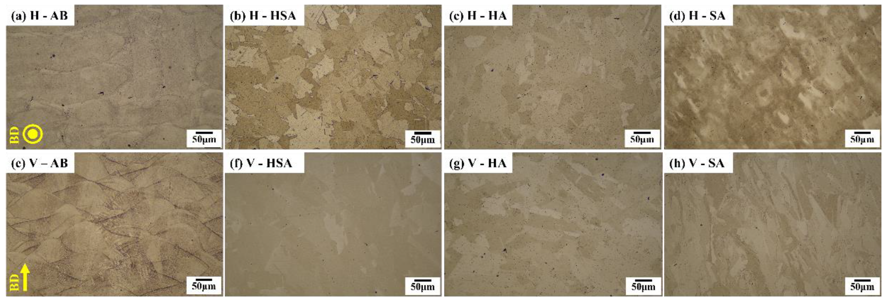
Figure 3 presents micrographs of specimens examined using an optical microscope, classified based on both build direction and heat treatment. In
Figure 3a,e, sub-grains are visible within the grains of AB specimens. The horizontal AB specimens exhibit a columnar structure of melt pools, with sizes ranging approximately from 300 to 400 μm. Conversely, the vertical AB specimens exhibit a long river structure of melt pools, with sizes around 250 μm, indicating varying melt pool structures based on the build direction. All HSA, HA, and SA specimens showed the disappearance of melt pools after heat treatment at high temperatures compared to the AB specimens. No indications of grain boundary or grain interior incipient melting were observed. This could be attributed to the finer substructure and the absence of low melting point precipitates within grain boundaries and interiors, likely resulting from the rapid solidification of the molten pool [
22].
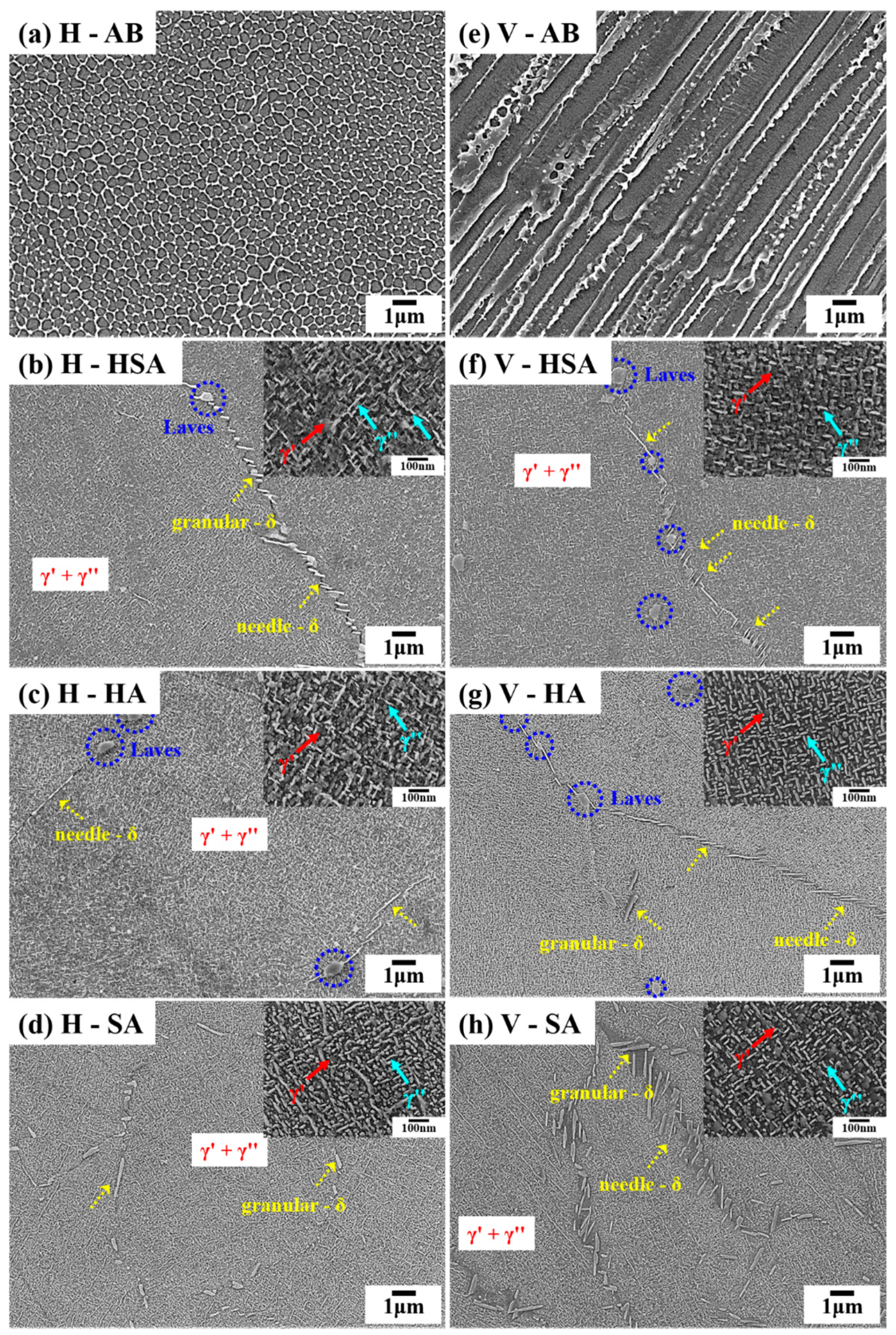
Figure 4 shows SEM images of the microstructures observed for different build orientations and heat treatments. Horizontal AB (
Figure 4a) samples exhibit a cellular structure, while vertical AB (
Figure 4b) samples display a fiber structure. The δ phase is distributed both within grains and at grain boundaries in HSA specimens (see
Figure 4b,f) and HA specimens (see
Figure 4c,g), while it is observed to be distributed only at grain boundaries in SA specimens (see
Figure 4d,h). At a lower solution temperature of 980 °C, the δ phase exhibits a needle and short rod-like morphology. The volume fraction of the δ phase at the grain boundary is significantly higher than that within the grain. This phenomenon occurs because the δ phase is formed through the dissolution of the Laves phase at the grain boundary and the presence of a large amount of Nb in the grain boundary. Additionally, the energy at the grain boundary is higher than that within the grain, leading to the preferential nucleation of the δ phase at the grain boundary [
23]. Both the Laves phase and δ phase were detected at the grain boundaries in HSA (see
Figure 4b,f) and HA (see
Figure 4c,g) specimens, indicating the presence of the Laves phase even after undergoing 1 h of homogenization treatment. In
Figure 4a,e, the AB specimens have no γ′ and γ″ precipitates. However, in the heat-treated specimens, both γ′ and γ″ phases were observed, as shown in the inset of
Figure 4, which was taken from the γ matrix. In
Figure 4b,f, γ′ and γ″ were precipitated to a lesser extent, with a significant presence of a needle-like δ phase. Conversely, in c and g, γ′ and γ″ were precipitated to a greater extent, resulting in fewer precipitates of the δ phase, with a distribution of needle-like δ phases along the grain boundaries. Finally, specimens subjected to SA heat treatment (
Figure 4d,h) exhibited proper precipitation of the γ′, γ″, and δ phases, with no observation of the Laves phase. This indicates that the Laves phase dissolved during heat treatment at 980 °C. Additionally, a significant amount of granular-δ phase was precipitated, which can be attributed to the complete dissolution and separation of the Laves phase. The high volume fraction of the δ phase is attributed to its rapid growth rate, even over a short period of time at around 980 °C. This resulted in a uniform distribution of γ″ and γ′ phases within the γ matrix. Atoms near the dissolved Laves phase exhibit higher kinetic energy, leading to the preferential nucleation of the δ phase around the dissolved Laves phase [
22]. In
Figure 4, the shapes of the precipitates of γ′ and γ″ are identified as spherical and disk-shaped, respectively. It is evident that the two forms of γ″ are positioned perpendicular to each other, as they develop on two distinct (100) planes within the γ matrix [
24]. Additionally, X-ray diffraction (XRD) was conducted, but no carbides were detected.
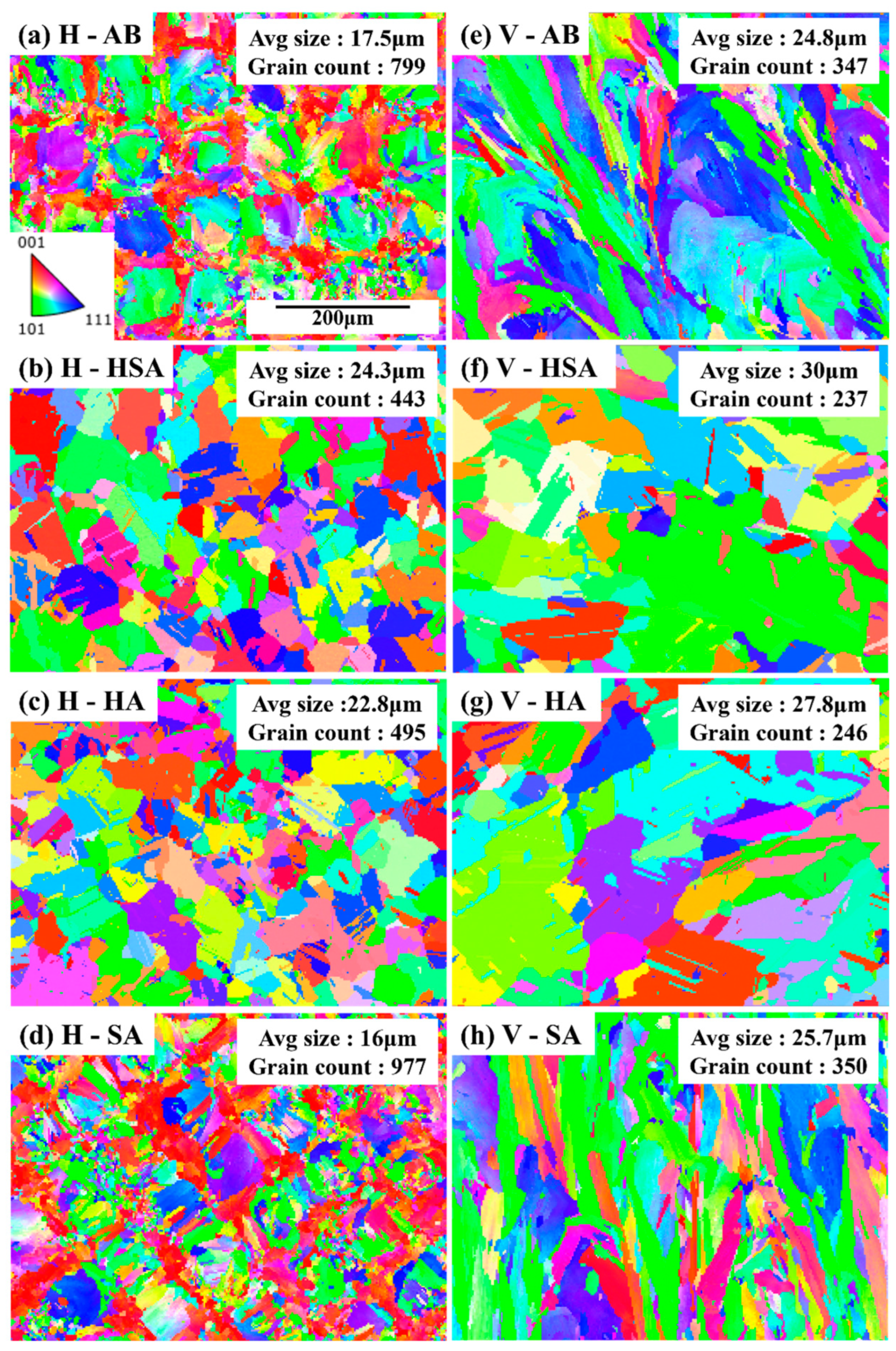
In
Figure 5, the EBSD microscopy images depict the microstructure of post-heat-treated specimens according to different build orientations. Compared to the V-AB state, in H-AB (
Figure 5a,e), distribution of finer microstructure can be observed. Additionally, the EBSD results show recrystallization occurring in both horizontal and vertical orientations in the HSA (
Figure 5b,f) and HA (
Figure 5c,g) specimens due to the homogenization treatment, with a more pronounced growth in microstructure compared to the AB specimens (
Figure 5a,e), along with the occurrence of annealing twins. Typically, samples are recrystallized after heat treatment to replace the unique SLM microstructure with homogeneous particles, annealed twins, and nano-sized precipitates. This process can significantly enhance the mechanical properties of the Inconel 718 alloy [
25,
26]. Similar to
Figure 3,
Figure 5 also demonstrates that the vertical specimens exhibit elongated microstructures almost parallel to the build direction compared to the horizontal specimens. Furthermore, specimens built with a vertical build direction (see
Figure 5e–h) show a larger grain size, due to thermal gradients, compared to the horizontal specimens. Layers built in the horizontal direction typically have shorter cooling times, allowing for faster grain growth. Therefore, the microstructure size in the horizontal direction is generally finer. On the other hand, layers built in the vertical direction may have longer cooling times due to the rapid transfer of heat between layers and restricted grain growth. Therefore, the microstructure size in the vertical direction is larger. This is caused by the heat flow during solidification, which is highest perpendicular to the surface of the pre-deposited layers. The direction of epitaxial grain growth depends on the direction of maximum heat flow. The maximum heat flow in the SLM process is observed in the building direction. The EBSD analysis shows qualitatively that no grain growth during the solution heat treatments took place (see
Figure 5d,h). In SLM, generally, the heat flow directions and thermal gradients in the laser scan tracks are complicated; thus, the microstructural development (i.e., crystal growth) is very complex, and is affected by a number of factors [
27,
28,
29].
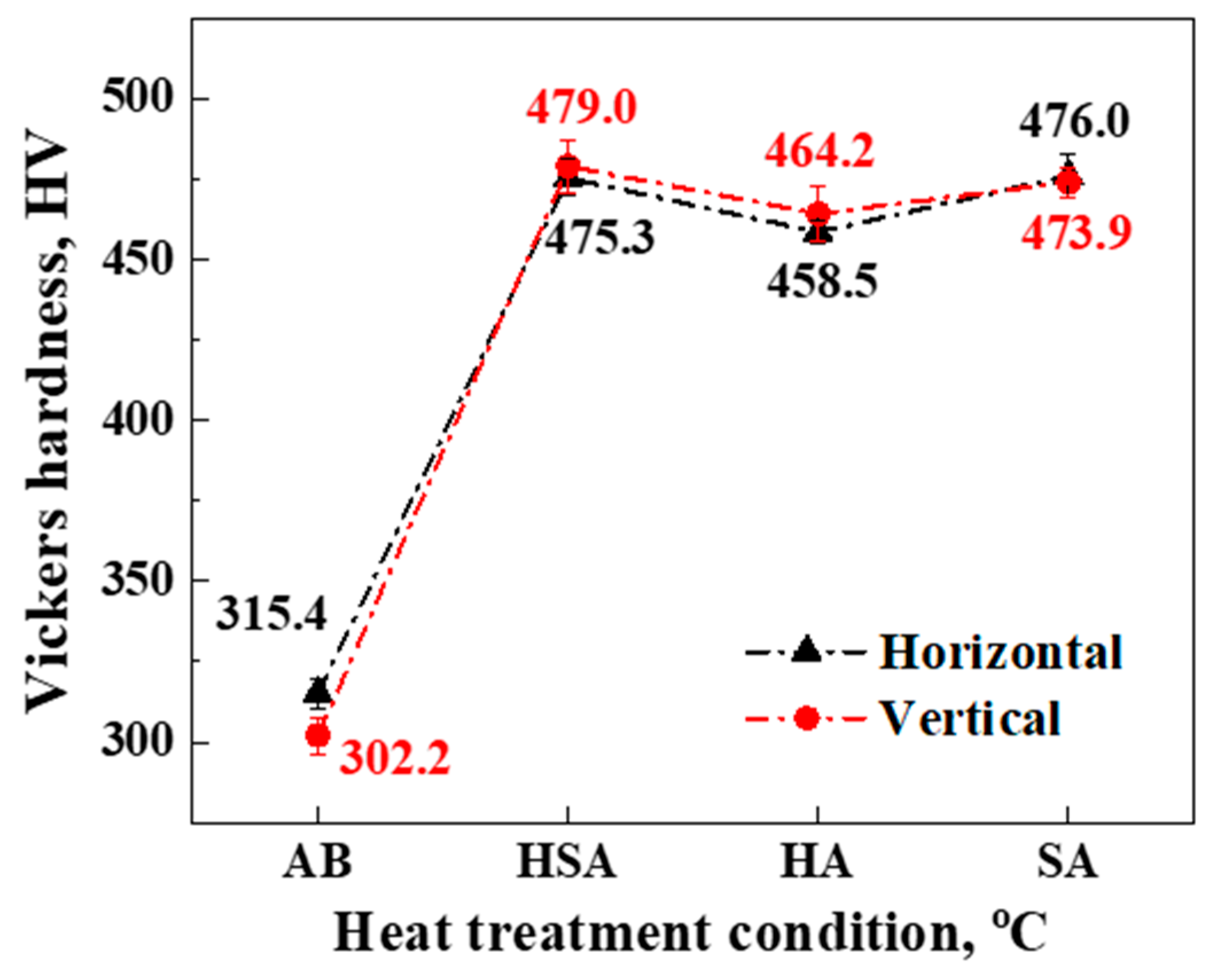
Figure 6 shows the Vickers hardness values of each sample. Heat-treated specimens demonstrate an approximately 52.57% increase in hardness compared to AB specimens. Notably, HSA exhibits the highest hardness among different heat-treated specimens, with measurements of 475.3 HV for the horizontal specimen and 479 HV for the vertical specimen. The reason for this is that in HSA, the δ-phase is finely distributed within both grain boundaries and grains. Additionally, needle-δ phase precipitates on particles can fix the grain boundaries and impede their movement, consequently enhancing the hardness of the alloy [
30]. Therefore, a specimen with a high distribution of needle-δ phases exhibited the highest hardness among the tested samples. As shown in
Figure 5, the EBSD results indicate grain counts of 799, 443, 495, and 977 for a–d, and 347, 237, 246, and 350 for e–h. Notably, SA exhibits the finest grain microstructure. Additionally, SA’s hardness of 476.0 ± 7.02 HV shows a similar trend to HSA’s hardness of 475.3 ± 5.7 HV, as illustrated in
Figure 6. In the solution annealing heat treatment, as shown in
Figure 4d,h, the needle-δ phase is restricted due to the formation of γ′ and γ″ precipitates. The most uniform distribution of γ is expected, leading to increased hardness. The γ′ and γ″ precipitates are observed after a double aging heat treatment. The δ phase depletes a significant amount of Nb; otherwise, γ′ and γ″ precipitates can be observed. However, their quantity and distribution uniformity vary depending on the heat treatment method. When some Nb is consumed, the δ phase forms along the grain boundaries. Therefore, Nb consumption around the δ phase creates regions devoid of γ″. The distribution of γ″ is more uniform when separated Nb is resolved in the precipitate state [
31]. In contrast, HA specimens showed the lowest hardness in both horizontal and vertical orientations. This is likely due to the uniform distribution and size of the Laves phase within the grains, as well as the consistent size and distribution of the δ-phase within both the grain boundaries and the grains themselves, as observed in
Figure 4. Moreover, the higher grain count measurements indicate a coarser microstructure, which contributes to the lower hardness observed in HA specimens. Obviously, grain refinement and the high-density behavior resulting from SLM additive manufacturing contribute significantly to the enhancement of micro-hardness. However, it is important not to overlook the impact of the intermetallic precipitate phase γ′ on microhardness. Furthermore, the γ′ phase not only enhances strength but also typically improves the component’s strength by forming lattice misfit and cohesive stresses due to its different lattice structure [
10].
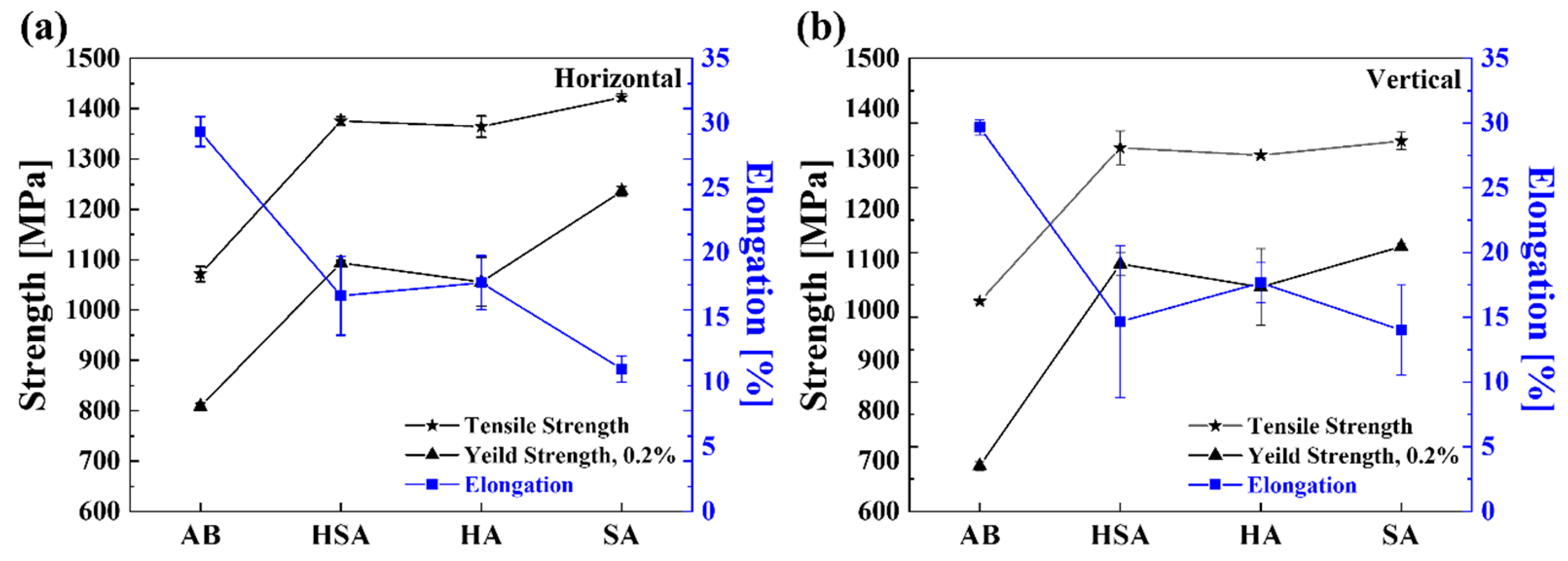
To analyze the effects of heat treatment on microstructure and mechanical properties, tensile tests were conducted at room temperature and 650 °C.
Figure 7 illustrates the results of the room temperature tensile tests. It can be observed that the AB specimens exhibit the lowest UTS, below 1100 MPa in both vertical and horizontal specimens, while their elongation is higher compared to the specimens subjected to heat treatment due to the absence of the strengthening phase. Conversely, the heat-treated specimens exhibited precipitation of strengthening phases, resulting in decreased elongation but enhanced tensile properties. For SA heat treatment with a horizontal building direction, not only did precipitated strengthening phases form, but a fine grain also developed. Additionally, the presence of the granular-δ phase resulted in an elongation of 11%, a tensile strength of 1422 MPa, and a yield strength of 1236 MPa, which are the highest values among the specimens. This observation suggests that specimens treated with SA, where Laves phases were absent, exhibited higher yield strength and tensile strength compared to HSA and HA specimens, where Laves phases were present. In our study, Laves phases were observed in specimens subjected to HSA (
Figure 4b,f) and HA (
Figure 4c,g), while specimens subjected to SA treatment (
Figure 4d,h) did not show any Laves phases. Conversely, both HSA and SA specimens with a vertical building direction showed an elongation of 14%, with tensile strengths of 1322.5 MPa and 1336 MPa, and yield strengths of 1091.6 MPa and 1126.3 MPa, respectively, indicating similar tensile properties. Different mechanical properties are observed due to the varying direction of tensile loading depending on the building direction. This is attributed to the anisotropy arising from the shape of the dendrites and the direction of grain growth within the melt pool. When tensile loading is applied perpendicular to the building direction, more grain boundaries are encountered. Grain boundaries hinder the movement of dislocations, implying that materials with a horizontal building direction demonstrate superior tensile strength and yield strength.
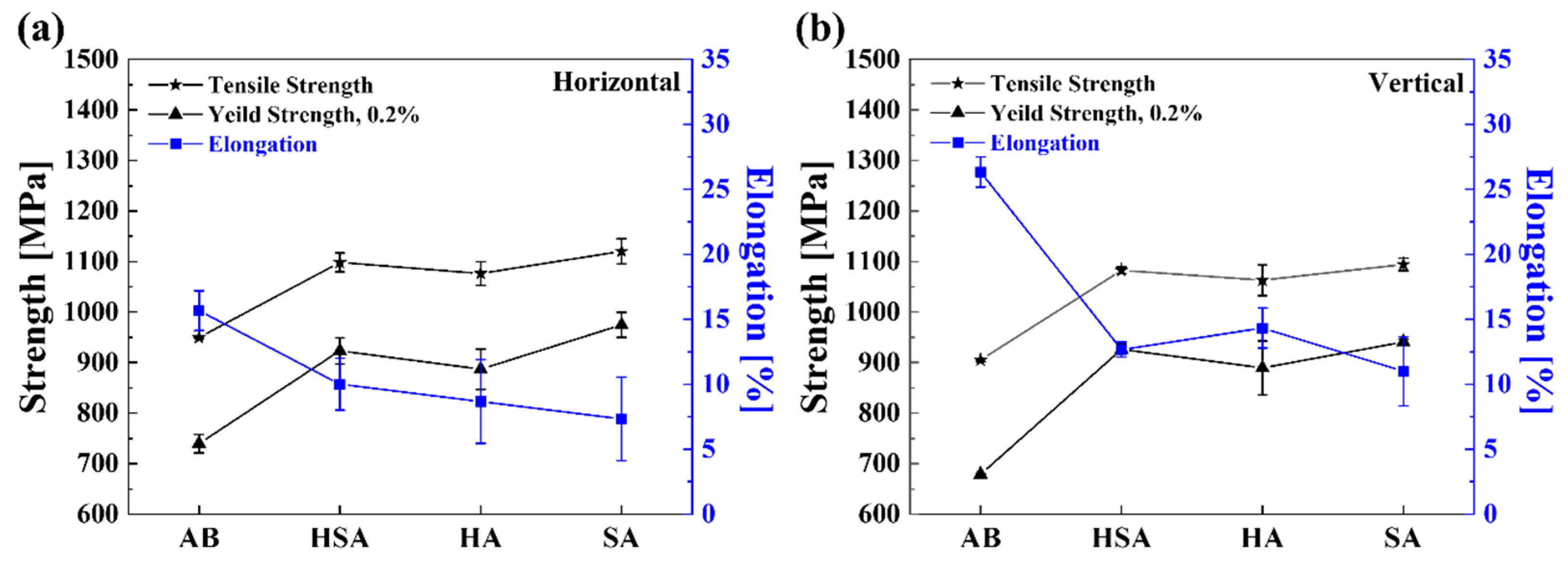
Figure 8 illustrates the high-temperature tensile properties of the SLMed Inconel 718 alloy at 650 °C with different heat treatments. It can be seen that the tensile properties of all specimens tested at elevated temperatures are reduced compared to those tested at room temperature. The reduction in strength is particularly noticeable in the annealed specimens. The tensile strengths of horizontally built specimens of HSA and HA are 1098 MPa and 1076 MPa, respectively, while SA exhibits a higher tensile strength of 1120 MPa. Furthermore, the yield strengths of the heat-treated specimens with a horizontal building direction are 923.3 MPa for HSA, 887 MPa for HA, and 974.6 MPa for SA, respectively. HSA and HA, which contain a substantial amount of needle or granular-δ phases, concentrate a significant proportion of Nb in the δ phase. As a result, they fail to precipitate sufficient γ′ and γ″ phases, resulting in weakened tensile strength at high temperatures. SA heat treatment exhibits the best tensile properties but lower elongation. Excessive δ phase at grain interiors and grain boundaries during high-temperature tensile tests can easily lead to localized stress concentration and microcrack initiation. However, the absence of the δ phase may lead to a decrease in high-temperature strength at grain boundaries, which can affect the high-temperature mechanical properties. Indeed, appropriate heat treatment can control the precipitation of the δ phase and further improve the high-temperature mechanical properties of SLM Inconel 718 alloy. The needle-δ phase clearly impedes the movement of dislocations. An increased presence of δ-phase precipitation in the SA specimens heightens the probability of dislocation aggregation and stress concentration near the δ phases, potentially culminating in microcrack formation and subsequent material failure [
32]. Thus, specimens heat-treated under SA conditions demonstrate optimal room temperature and high-temperature characteristics, specifically superior tensile and yield strength.
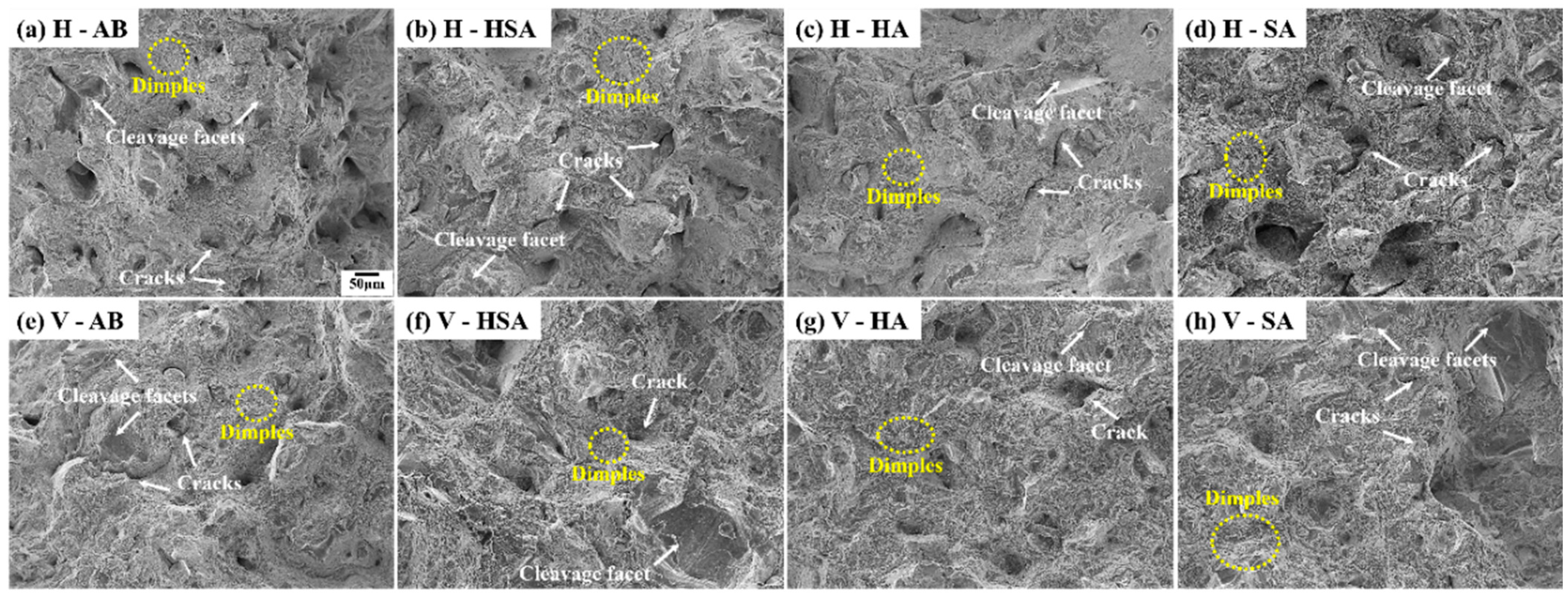
Figure 9 presents a SEM analysis of the fracture surfaces of specimens subjected to different heat treatments after post-tensile testing conducted at room temperature. Every sample exhibits brittle and ductile fracture zones in the fracture morphologies, indicating a mixed fracture mode. AB specimens (
Figure 9a,e) exhibit a small distribution of dimples, and cracks are observed to be larger compared to other heat-treated specimens. HA and HSA specimens have a high number of dimples, but they are shallow and prominent with cleavage facets (
Figure 9c,g). The presence of Laves phases in HSA and HA specimens induces micro-segregation of Nb elements, leading to an uneven distribution of γ″ phases. Segregation at grain boundaries results in stress concentration around Laves phases and decreased tensile ductility [
14,
33]. The SA specimens (
Figure 9d,h) displayed fracture surfaces with distinctive rough grooves, setting them apart from those of other heat-treated samples. Moreover, smaller and deeper dimples were discernible, facilitating the dispersal of internal stresses and mitigating stress concentration. This enhancement increased the material’s ability to absorb energy before failure, resulting in higher yield and tensile strength, as well as reduced elongation, as supported by the findings presented in
Figure 7. Additionally, the density and distribution of dimples in the SA heat-treated specimens were observed to be higher than those in other samples. The number of dimples per unit area on the fracture surface is related to the location and quantity of pore nucleation, as well as the material plasticity. The greater the number of nucleation positions and dimples, the more intersecting cracks and dimples there will be. Therefore, crack propagation is more difficult to initiate; thus, an increase in tensile strength is expected [
34].
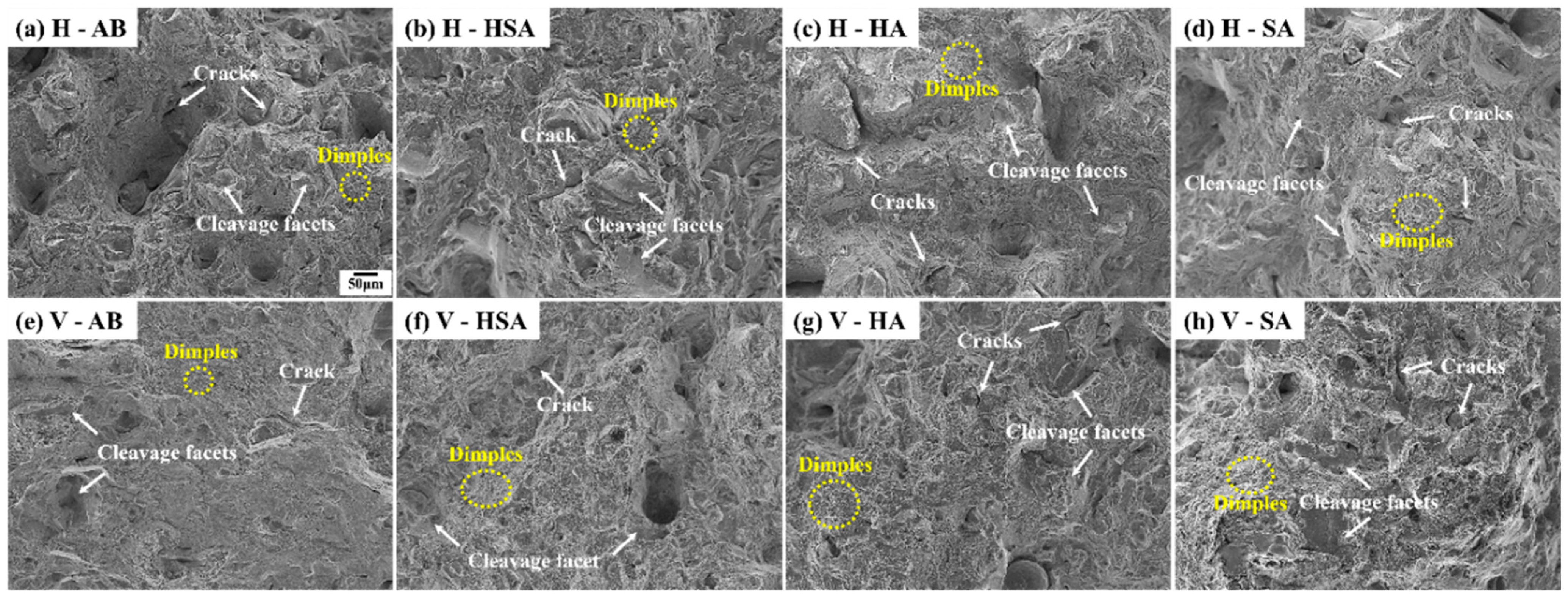
Figure 10 shows an SEM image analyzing fracture surfaces after high-temperature tensile testing at 650 °C. Similar to
Figure 9, the image depicts a mixed fracture mode with both ductile and brittle fracture regions. Overall, the high-temperature tensile test results showed lower tensile strength and yield strength compared to room temperature tensile testing. This is mainly evident because dislocations are able to move more easily at higher temperatures. Another factor contributing to this phenomenon is the reduction in material bond strength as the average distance between atoms increases at elevated temperatures [
35,
36,
37]. In the high-temperature tensile testing, the size of dimples observed in all specimens was larger compared to the room temperature fracture, indicating a reduction in ductility as the density of dimples significantly decreased in the fractures at 650 °C. Additionally,
Figure 10 reveals fewer coarse, jagged grooves, and generally smoother and more uniform surfaces were observed. AB specimens exhibited the lowest elongation among the tensile test results because of the abundance of large cracks and numerous cleavage facets observed in
Figure 10a. Moreover,
Figure 10e depicts a high prevalence of cleavage facets alongside a reduced distribution of dimples, correlating with the lowest recorded yield strength and tensile strength results. On the contrary, specimens that underwent post-heat treatments (
Figure 10b–d,f–h) showed finer cracks and smaller cleavage facets compared to the AB specimens. As a result, it can be inferred that the high-temperature strength was higher in these specimens. Specimen V-HA exhibited larger dimples compared to V-HSA, resulting in a higher elongation. In
Figure 10c, a large crack composed of merged fine cracks was observed, and the fine microcracks in HSA (
Figure 10b,f) and HA (
Figure 10c,g) were found to originate from the presence of Laves and δ phases. It is anticipated that these cracks are induced by the presence of Laves phases and needle-δ phases. Such brittle phases provide easy crack propagation paths, accelerating damage and indicating unfavorable conditions for high-temperature tensile properties.


