Article

Study on the Effect of Solid Solution Treatment on the Bending Fatigue Property of Fe-Mn-Si Shape Memory Alloys

Department of Mechanics, Dalian Maritime University, Dalian 116026, China
*
Author to whom correspondence should be addressed.
Metals 2024, 14(4), 441; https://doi.org/10.3390/met14040441
Submission received: 14 March 2024 / Revised: 6 April 2024 / Accepted: 8 April 2024 / Published: 10 April 2024

Abstract

:
Fe-Mn-Si shape memory alloys have excellent low-cycle fatigue performance and broad application prospects in the field of civil engineering and construction. It is necessary to conduct comprehensive and in-depth research on the mechanical properties of Fe-Mn-Si shape memory alloys. This study takes the Fe17Mn5Si10Cr5Ni shape memory alloy as the research object. After solid solution treatment at different temperatures and times, the effect of solid solution treatment on the bending fatigue performance of Fe-Mn-Si shape memory alloys was studied using bending cycle tests. The phase composition and fracture morphology of the sample were analyzed. The results showed that solid solution treatment can significantly improve the bending fatigue performance of Fe-Mn-Si shape memory alloys, reaching the optimal value at 850 °C for 1 h. The number of bending cycles until fracture increased by 131% compared to untreated specimens. Stress induction γε martensitic transformation occurred in Fe-Mn-Si shape memory alloy specimens during bending cyclic testing, which is reversible. The fracture area of Fe-Mn-Si shape memory alloy specimens is mainly characterized by ductile fracture, with some areas exhibiting quasi-quasi-cleavage fracture characteristics.

1. Introduction

Fe-based shape memory alloys have the advantages of shape memory effect, excellent mechanical properties, low raw material cost, and can be mass-produced using traditional steelmaking methods and processing equipment, and they are increasingly receiving attention from researchers [1]. The Fe-Mn-Si shape memory alloy has the most research space and practical value among Fe-based shape memory alloys. Researchers have conducted extensive research on Fe-Mn-Si shape memory alloys, improving their shape memory effect by adding trace elements such as C, N, V, and Nb [2,3,4], and using thermal mechanical training [5,6,7,8,9] methods. However, the shape memory recovery rate of this alloy is low, and its forming and processing performance is poor; there are not many research achievements that can truly be applied to practical engineering [10,11]. In addition, Fe-Mn-Si shape memory alloys have a certain degree of pseudoelasticity [12]. The pseudoelasticity of Fe-Mn-Si shape memory alloys is related to the stress induced martensitic transformation inside the material. Compared with Ni-Ti shape memory alloys, the proportion of stress-induced martensitic transformation in Fe-Mn-Si shape memory alloys is limited [13,14]. Therefore, the pseudoelasticity of Fe-Mn-Si shape memory alloys is much lower than that of Ni-Ti shape memory alloys [15], and its application is limited.
Fe-Mn-Si shape memory alloys were initially applied in the rail and pipeline industry. Its application in the civil engineering and construction industries is to use shape memory effect to generate prestress inside the structure. The prestressing of Fe-Mn-Si shape memory alloys can enhance the flexural strength and cracking stress of concrete structures [16,17,18]. When Fe-Mn-Si shape memory alloys are applied to prestressed structures, researchers pay more attention to the magnitude of the prestress generated by the material. Different levels of prestressing can be achieved by changing the pre-strain level and recovery temperature [19,20,21,22,23,24].
With the continuous deepening of research on the application of Fe-Mn-Si shape memory alloys in the field of civil engineering and construction, researchers have found that they have excellent low-cycle fatigue performance [25,26,27]. The study of the mechanical properties of Fe-Mn-Si shape memory alloys has become a new, hot direction. Sawaguchi et al. [28] studied the damping characteristics of Fe-28Mn-6Si-5Cr-0.5NbC shape memory alloys under low-cycle fatigue test conditions, as well as its deformation mechanism under cyclic tensile and compressive loads. The results showed that the specific damping capacity increased with the increase of strain amplitude; X-ray diffraction analysis and microstructure observation indicate that a large amount of tensile-stress-induced ε martensite undergoes subsequent compression reversal to γ austenite, which refers to the stress-induced martensitic reverse transformation in alloys. Sawaguchi et al. [29] also proposed a new design concept to improve the low-cycle fatigue life of Fe-Mn-Si shape memory alloys by changing the stacking fault energy to enhance the reversibility of dislocation motion. Koster et al. [30] studied the behavior of Fe-17Mn-5Si-10Cr-4Ni-1 (V, C) shape memory alloys under cyclic loading and found that a transition from high-cycle fatigue to low-cycle fatigue occurred when the stress was significantly higher than the elastic limit of the alloy. Ghafoori et al. [31] studied the high-temperature mechanical properties of Fe-based shape memory alloy prestressed reinforced structural components and found that under all different working conditions, the creep initiation temperature of the material was higher than 500 °C; The starting temperature and failure temperature of creep decrease with the increase of load level; An engineering model has been established to estimate the prestress loss caused by high temperatures in structures. Ghafoori et al. [32] also investigated the effect of strain rate on the stress–strain behavior of Fe-17Mn-5Si-10Cr-4Ni-1 (V, C) shape memory alloys, and evaluated the fatigue behavior of the alloy after pre-strain and thermal activation under strain control conditions. Qiu et al. [33] added the Fe-Mn-Si shape memory alloy to the buckling-restrained brace structure and studied its seismic performance. Compared with traditional steel structures, the main advantage of Fe-Mn-Si shape memory alloy buckling-restrained brace structures is that they can better control the residual interlayer displacement angle. Research on Fe-Mn-Si shape memory alloys has achieved certain results, but most of the research has focused on the low-cycle fatigue performance of the alloy [34,35,36,37], and its application is limited to dampers [38] and support structures [39]. Therefore, in order to broaden the application range of Fe-Mn-Si shape memory alloys, it is of great significance to conduct comprehensive and in-depth research on the mechanical properties of Fe-Mn-Si shape memory alloys.
This study investigated the effect of solid solution treatment on the bending fatigue performance of Fe-Mn-Si shape memory alloys through bending cycle tests. After solid solution treatment at different temperatures and times, Fe-Mn-Si shape memory alloys were subjected to bending cycle tests under the same conditions. The internal phase changes of the materials were analyzed using X-ray diffraction (XRD), and the fracture morphology of the materials was observed using field-emission scanning electron microscopy (SEM).

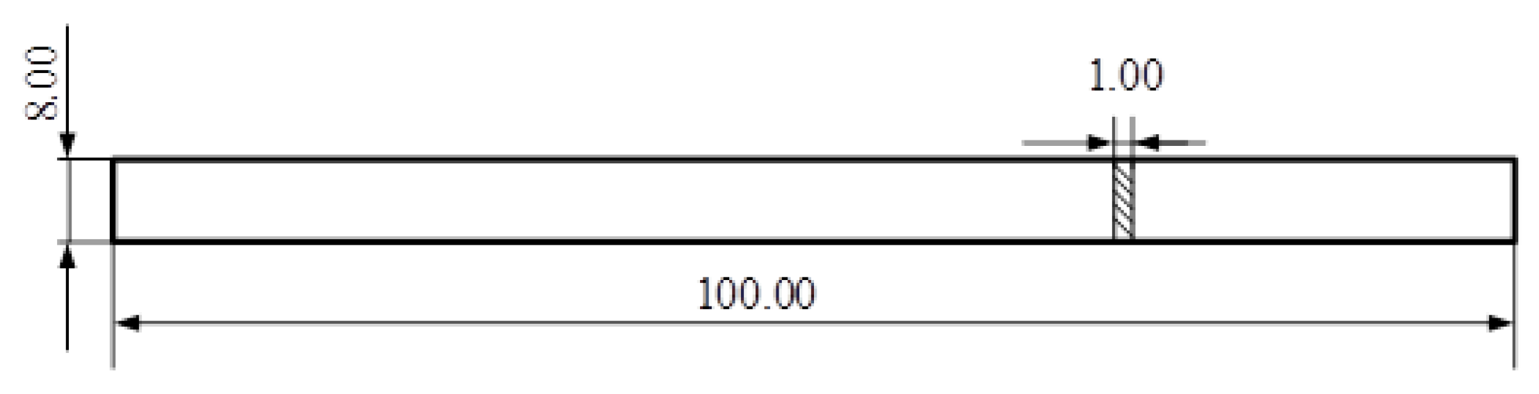
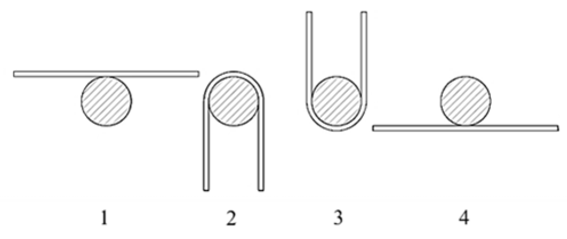
2. Materials and Methods

The alloy material used in the experiment is an Fe17Mn5Si10Cr5Ni shape memory alloy, which is made by smelting industrial pure iron, manganese, silicon, chromium, and nickel in a vacuum induction furnace (ALD, Hanau, Germany) according to the elemental composition ratio. During smelting, wait for the raw materials to melt, keep them warm for 30 min to ensure even composition, and then proceed with metal casting. After annealing at 1200 °C for 24 h, remove the cap and outer skin of the ingot, and forge it at 1200 °C to produce Φ 80 mm of bar material. The material composition is shown in Table 1. To compare the bending fatigue performance of experimental materials, 304 stainless steel material was selected as the comparative material, which is also an austenitic matrix.
The bending fatigue specimen is processed by wire cutting, and the test material is cut into bending fatigue specimens of 100 mm × 8 mm × 1 mm. The dimensions of the specimens are shown in Figure 1. In order to study the effect of the solid solution treatment process on the bending fatigue performance of Fe-Mn-Si shape memory alloys, the specimens were subjected to different conditions of solid solution treatment in a vacuum heating furnace. The solid solution treatment temperatures were 750 °C, 850 °C, 950 °C, 1050 °C, and 1150 °C, and the time was 1 h and 3 h.
The bending fatigue tests in this study were all conducted at normal atmospheric temperature. The bending fatigue test was conducted using a self-made mold, and the principle of the test process is shown in Figure 2. According to the size of the specimen and the diameter of the mold, the bending strain was controlled to ±5%, and bending cycles on each group of specimens were performed until final fracture. At the same time, in order to study the phase changes of Fe-Mn-Si shape memory alloy specimens during the experimental process, after obtaining the optimal solution treatment process, the Fe-Mn-Si shape memory alloy specimens treated with the optimal solution treatment process were subjected to cyclic bending once, 5 times, 10 times, and 100 times, respectively, until final fatigue fracture.
The phase change analysis of the specimen was conducted using a D/MAX-3A X-ray diffractometer (RIGAKU, Tokyo, Japan), with Cu target radiation, a working voltage of 40 KV, a current of 40 mA, a scanning speed of 4°/min, and a scanning angle of 30°~75°. The fracture morphology of the specimen after fracture was observed and analyzed using field-emission scanning electron microscopy (ZEISS, Oberkochen, Germany).
In order to quantitatively analyze the phase changes of materials during the experimental process, the phase composition in the X-ray diffraction pattern was quantitatively analyzed by direct comparison method. The direct comparison method is commonly used for quantitative analysis of residual austenite or other isomeric transformation products in quenched steel. Therefore, it is suitable for quantitative analysis of the phase composition of Fe-Mn-Si shape memory alloys and 304 stainless steels.
The polycrystalline diffraction Intensity measured by the X-ray diffractometer can be expressed as follows:
I = K R 2 μ V
where K is a constant independent of the type and content of the diffracted material; R is a proportional constant related to diffraction angle, crystal plane index, and the type of material being tested; V is the volume of the measured substance irradiated by X-rays; and μ is the absorption coefficient of the sample.
If the volume fractions of γ, ε and α′ phases are Cγ, Cε, and Cα, Equation (2) can be obtained:
{ I γ = K R γ C γ V 2 μ I ε = K R ε C ε V 2 μ I α = K R α C α V 2 μ C γ + C ε + C α = 1
Therefore, the volume fractions of phases can be obtained from Equation (2) as follows:
{ C γ = 1 1 + R γ R ε I ε I γ + R γ R α I α I γ C ε = 1 1 + R ε R γ I γ I ε + R ε R α I α I ε C α = 1 1 + R α R γ I γ I α + R α R ε I ε I α
For 304 stainless steel, there are only γ and α′ phases, Cε = 0, and Equation (3) becomes the following:
{ C γ = 1 1 + R γ R α I α I γ C α = 1 1 + R α R γ I γ I α
For Fe-Mn-Si shape memory alloy, there are γ and ε phases, Cα = 0, and Equation (3) becomes the following:
{ C γ = 1 1 + R γ R ε I ε I γ C ε = 1 1 + R ε R γ I γ I ε
When using Equations (4) and (5) for calculation, Iγ, Iε, and Iα can be directly measured by X-ray diffraction pattern; Rγ, Rε, and Rα can be calculated from Equation (6).
R = P F 2 V c 2 ( 1 + cos 2 2 θ sin 2 θ cos θ ) e 2 M
where P is the multiplicity factor, which can be derived from the crystal structure and crystal plane index.; F2 is the unit cell diffraction intensity (structural factor), which includes atomic scattering factors; ( 1 + cos 2 2 θ sin 2 θ cos θ ) is the angle factor; e 2 M is the temperature factor, which can be calculated from Equation (7); and Vc is the volume per unit cell, which can be calculated by Equation (8).
M = 6 h 2 m a k Θ [ φ ( χ ) χ + 1 4 ] sin 2 θ λ 2
where h is the Planck constant, h = 6.626 × 10⁻³⁴ J·s; ma is the atomic mass, ma = A × 1.66 × 10⁻²⁴ g, A is the atomic weight of the element; k is the Boltzmann constant, k = 1.38 × 10⁻²³ J/K; Θ is the average value of the Debye characteristic temperature; χ is the ratio of the Debye characteristic temperature to the absolute temperature of the sample during spectral photography; and φ ( χ ) is the Debye equation.
V γ = a γ 3 V ε = 3 3 2 a ε 2 c ε V α = a α 3
The lattice constants of the γ and α′ phases can be calculated using Equation (9).
λ 2 sin θ = a h 2 + k 2 + l 2
The lattice constant of the ε phase can be calculated using Equation (10).
λ 2 sin θ = 1 4 / 3 ( h 2 + h k + k 2 ) / a 2 + l 2 / c 2

3. Results and Discussions

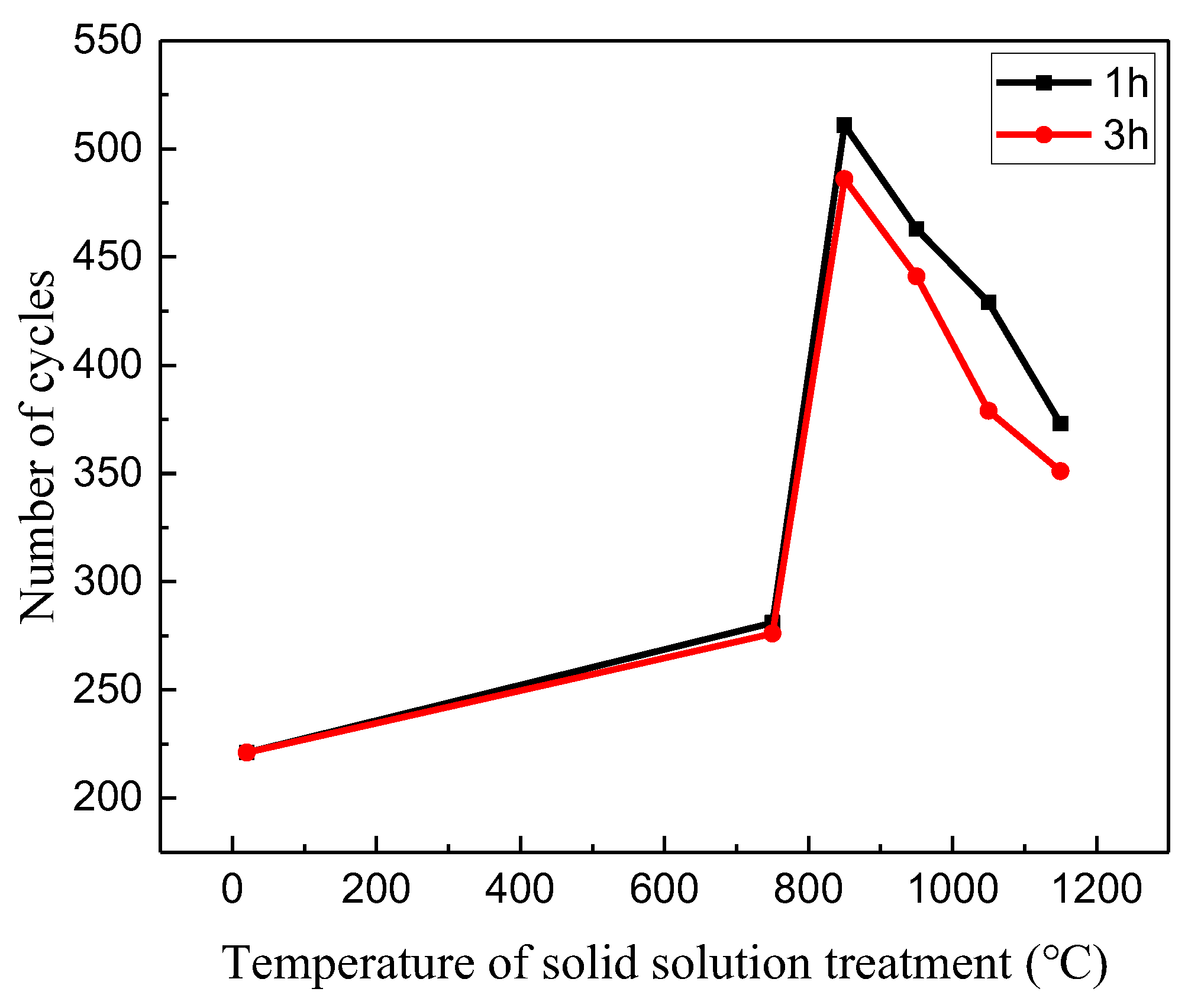
3.1. The Number of Bending Cycles

Under the condition of controlling the bending strain to ±5%, the number of bending cycles until fracture of the Fe-Mn-Si shape memory alloy after different solid solution treatment processes is shown in Table 2 and Figure 3. According to Table 2, the number of bending cycles until fracture for specimens without solid solution treatment was 221. The number of bending cycles until fracture for specimens with solid solution treatment increased, reaching a maximum of 511 under the condition of 850 °C solid solution treatment for 1 h. The number of cycles increased by 131% compared to untreated specimens. As shown in Figure 3, with the increase of solid solution temperature, the number of bending cycles until fracture for specimens first increases and then decreases, reaching its maximum at 850 °C. Under the condition of constant solid solution temperature, the number of cycles at which the specimen with a solid solution time of 3 h experiences fracture is slightly lower than that of the specimen with a solid solution time of 1 h. Under the same experimental conditions, the 304 stainless steel specimen rapidly fractured after 43 bending cycles, indicating that the bending fatigue performance of Fe-Mn-Si shape memory alloy is much better than that of 304 stainless steel.

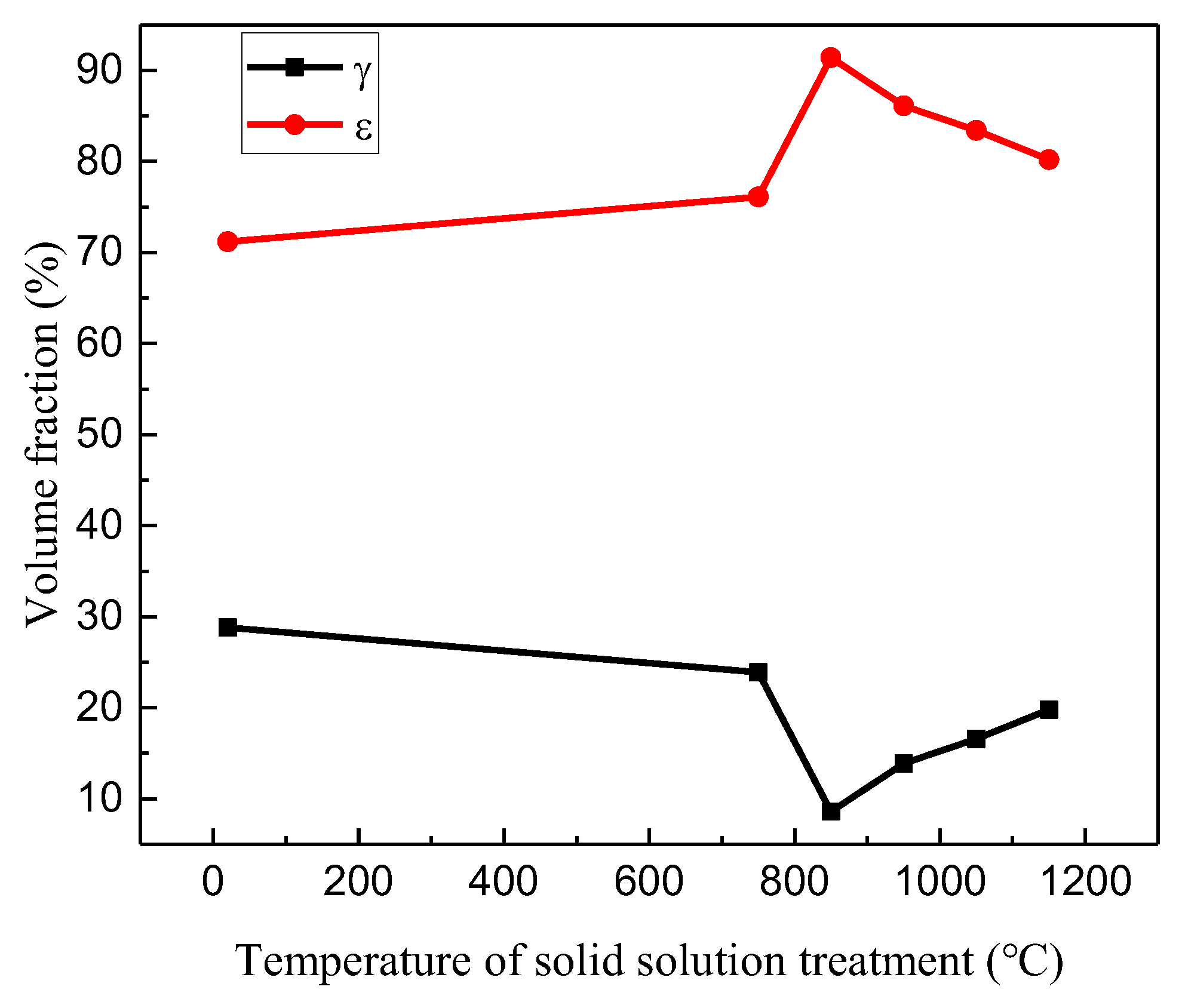
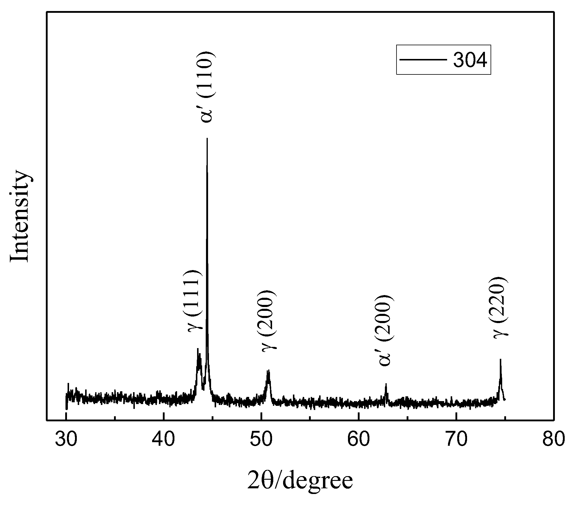
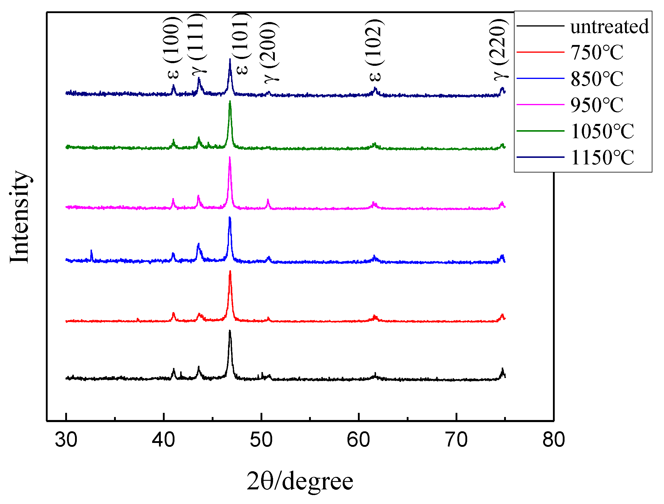
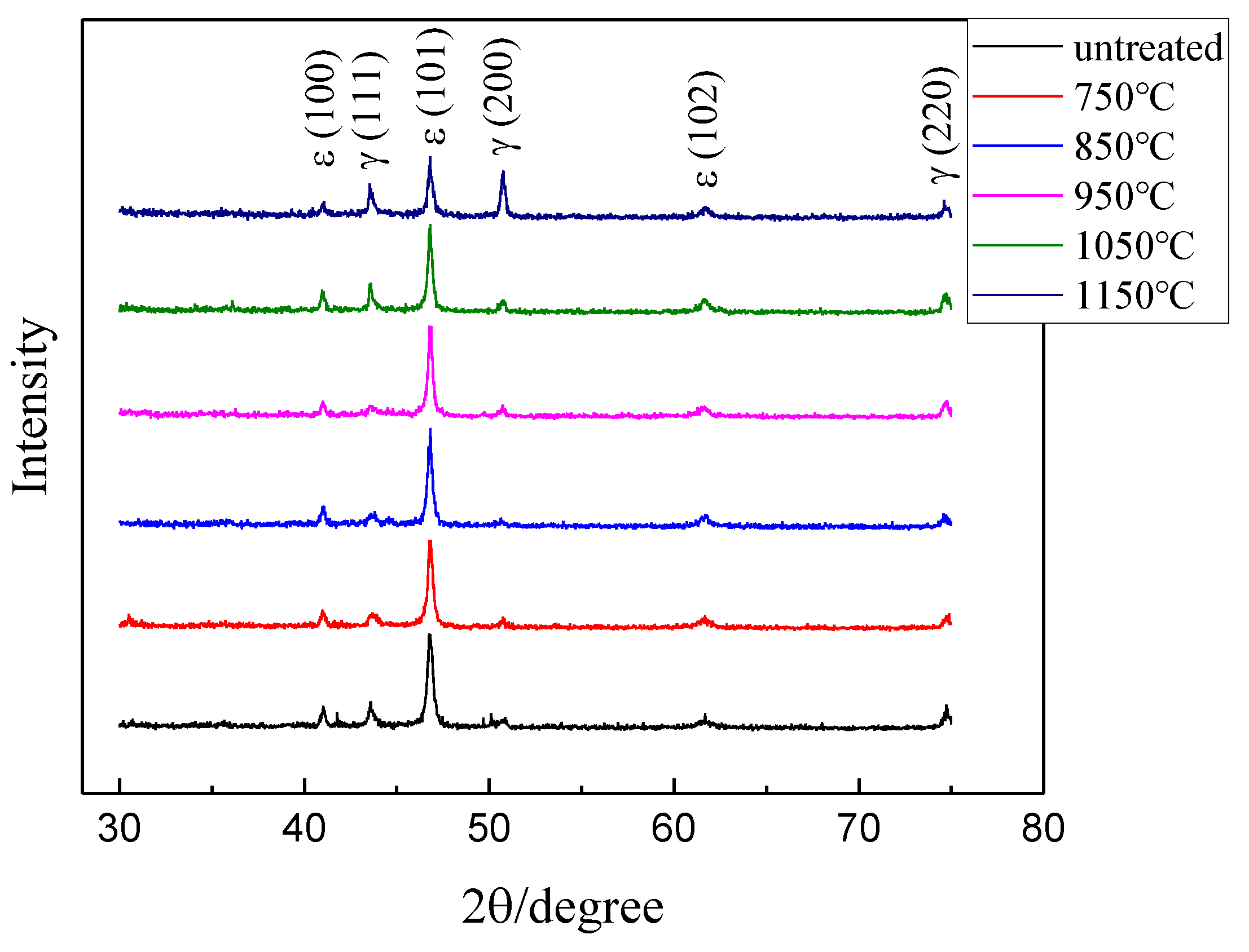
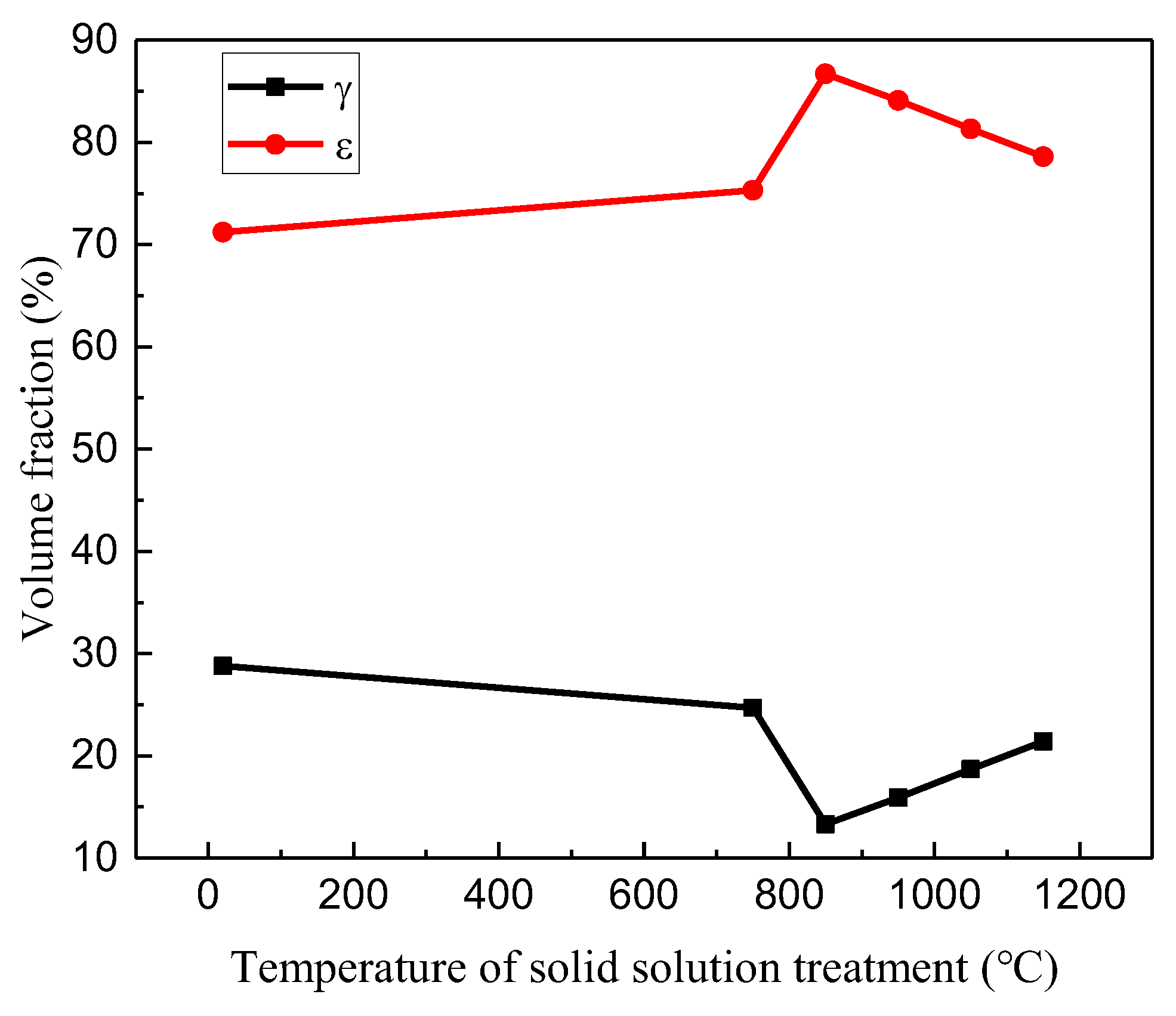
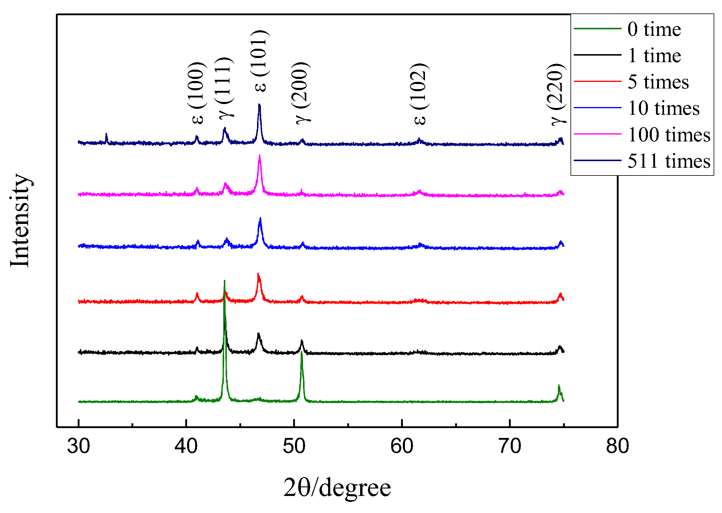
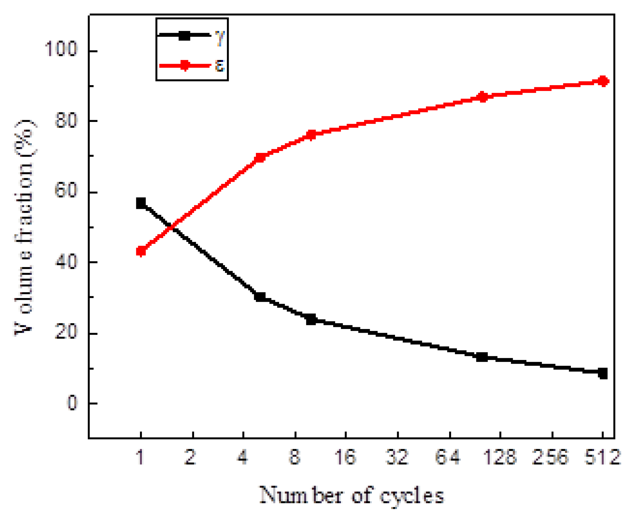
3.2. Analysis of Phase Changes

In order to investigate the influencing mechanism of the solid solution treatment process on the bending fatigue performance of Fe-Mn-Si shape memory alloys, XRD was used to analyze the phase composition of the specimens. Figure 4 shows the XRD pattern of 304 stainless steel specimen fracture after 43 bending cycles, with diffraction peaks composed of γ austenite and α′ martensite. Before the bending cycle test, the parent phase of 304 stainless steel was stable γ austenite. With the progress of the bending test, the diffraction peak area of γ austenite decreased and the diffraction peak area of α′ martensite increased, indicating that γα′ martensitic transformation occurred during the bending process. By using the direct comparison method to quantitatively analyze the phase composition in the XRD pattern, it was found that the volume fraction of α′ martensite and γ austenite in 304 stainless steel after bending cycling until fracture under ±5% strain conditions was 94.7% and 5.3%, respectively. This indicates that the vast majority of γ austenite transformed into α′ martensite during the bending test process.
Figure 5 shows the XRD patterns of Fe-Mn-Si shape memory alloy specimens subjected to bending cycles until fracture with different solid solution treatment temperatures for 1 h. The diffraction peaks are composed of γ austenite and ε martensite, indicating that γε martensite transformation occurred during the experiment, and no α′ martensite was generated inside the material, which is different from 304 stainless steel. Figure 6 shows the volume fraction of Fe-Mn-Si shape memory alloy specimens subjected to bending cycles until fracture with different solid solution treatment temperatures for 1 h. The lowest volume fraction of ε martensite in the untreated specimens is 71.2%, while the lowest volume fraction of ε martensite in all specimens subjected to solid solution treatment is 76.1%, reaching a maximum of 91.4% at 850 °C. Compared with the experimental results of 304 stainless steel, it can be seen that the bending fatigue performance of the Fe-Mn-Si shape memory alloy is much better than that of 304 stainless steel, because stress-induced γε martensitic transformation occurs inside it, and the amount of γε martensitic transformation has a significant impact on its bending fatigue performance.
Figure 7 shows the XRD patterns of Fe-Mn-Si shape memory alloy specimens subjected to bending cycles until fracture with different solid solution treatment temperatures for 3 h. The diffraction peaks are also composed of γ austenite and ε martensite. Figure 8 shows the phase volume fraction of Fe-Mn-Si shape memory alloy specimens subjected to bending cycles until fracture with different solid solution temperatures for 3 h. The lowest ε martensitic volume fraction of all specimens treated with solid solution treatment was 75.3%, and the highest reached 86.7% at 850 °C. The trend of change is the same as that of the specimens treated with solid solution treatment for 1 h.
Figure 9 shows the XRD patterns of Fe-Mn-Si shape memory alloy specimens treated with the best solid solution process (850 °C, 1 h) after different bending cycles. In theory, the phase composition of the specimen treated with solid solution before the bending test is only γ austenite. However, from Figure 9, it can be seen that there is a very small amount of ε martensite inside the material before the experiment. The reason is that the stress-induced martensite is caused by the stress during the sample preparation process. After one bending cycle, the diffraction peak intensity of ε martensite increases significantly, while the diffraction peak intensity of γ austenite decreases significantly. As the experiment progresses, the diffraction peak intensity of ε martensite continues to increase, while the diffraction peak intensity of γ austenite continues to decrease. This phenomenon indicates that γε martensitic transformation occurs inside the material during bending cycles. Figure 10 shows the phase volume fraction of Fe-Mn-Si shape memory alloy specimens treated with the best solid solution process after different bending cycles. After one bending cycle, the γ austenite content inside the specimen decreases to 56.8%, and the ε martensite content increases to 43.2%. As the experiment progresses, the γ austenite content inside the specimen continuously decreases, while the ε martensite content continuously increases. After 10 bending cycles, the content of ε martensite increases to 71.1%, and the rate of increase in ε martensite content was significant during this process. When the number of bending cycles exceeds 10, the rate of increase in ε martensite content gradually slows down. Until the specimen fractures, the γ austenite content inside the specimen decreases to 8.6%, and the ε martensite content increases to 91.4%. The experimental phenomenon indicates that γε martensitic transformation occurs inside the Fe-Mn-Si shape memory alloy during bending cycles. According to the research of Sawaguchi et al. [28], this phase transition is reversible. When a material undergoes stress-induced martensitic transformation under the action of stress in a certain direction, and then applies stress in the opposite direction to the material, the martensite inside the material will reverse into austenite, resulting in stress-induced martensitic reverse transformation. It is precisely this repeated forward-and-reverse-phase transformation that makes Fe-Mn-Si shape memory alloys exhibit significantly higher fatigue performance than ordinary metal materials. For the same reason, when subjected to external cyclic stress, Fe-Mn-Si shape memory alloys adapt to changes in macroscopic stress induced γε martensitic transformation and its reverse transformation, thereby reducing the peak stress inside the material, reducing stress concentration, delaying the propagation of fatigue cracks, and improving its fatigue life.
Generally, the microstructure of Fe-Mn-Si shape memory alloys is composed of austenite phase. During the hot forging process, deformation energy storage exists in the austenite grains in the form of dislocations, lattice defects, etc., and the grain boundaries are often in a rough and uneven shape. The alloy, after hot forging, has a higher total free energy, and during the solution treatment process, the free energy of the alloy will be reduced through recrystallization. Therefore, the grain boundaries after solid solution treatment will become straighter and more uniform. Solid solution treatment can eliminate the stress-induced martensite in Fe-Mn-Si shape memory alloys during the forging process, and the grain size gradually increases with the increase of solid solution temperature. However, if the temperature is too high, overheating will occur, leading to excessive grain growth. The number of stress-induced martensite during bending cycles is an important factor affecting the fatigue performance of Fe-Mn-Si shape memory alloys. The generation of stress-induced martensite can reduce plastic deformation caused by dislocation slip. Therefore, in order to improve the fatigue performance of Fe-Mn-Si shape memory alloys, as much stress-induced martensite as possible should be generated during the bending process, and the plastic deformation caused by full dislocation slip should be reduced. Improving the strength of austenite and reducing the critical stress for stress-induced martensitic transformation are beneficial for the occurrence of stress-induced martensitic transformation inside Fe-Mn-Si shape memory alloys. After hot forging, there are many dislocations and defects in the grain of Fe-Mn-Si shape memory alloy, and the grain boundaries are irregular. These factors are not conducive to the occurrence of stress-induced martensitic transformation inside the alloy. The reduction of defects and dislocations in the internal grains of Fe-Mn-Si shape memory alloy after solid solution treatment is beneficial for stress-induced martensitic transformation and its reverse transformation, thereby improving the fatigue performance of the alloy. When the solid solution temperature is low, the grain size of the alloy is smaller, the strength of the parent phase is higher, and the critical stress for stress-induced martensitic transformation is higher. During the transformation process, slip deformation is less likely to occur, which is conducive to the occurrence of stress-induced martensitic transformation. On the other hand, there are a large number of defects and dislocations inside the grains, which are not conducive to stress-induced martensitic transformation, and this factor plays a major role. The increase in solution treatment temperature and the extension of time will cause the grain to become larger, reduce the defects and dislocations inside the grain, and make the grain boundaries more regular. These factors are conducive to the occurrence of stress-induced martensitic transformation. On the other hand, the critical stress for stress-induced martensitic transformation inside the alloy will decrease, leading to slip deformation in the alloy during the phase transformation process, which is not conducive to the stress-induced martensitic transformation, and this factor plays a major role. At a solid solution temperature of 850 °C for 1 h, the internal defects of the alloy, the strength of the parent phase, and the critical stress of stress-induced martensite reach the optimal combination. At this point, the fatigue performance of Fe-Mn-Si shape memory alloy reaches its optimum.

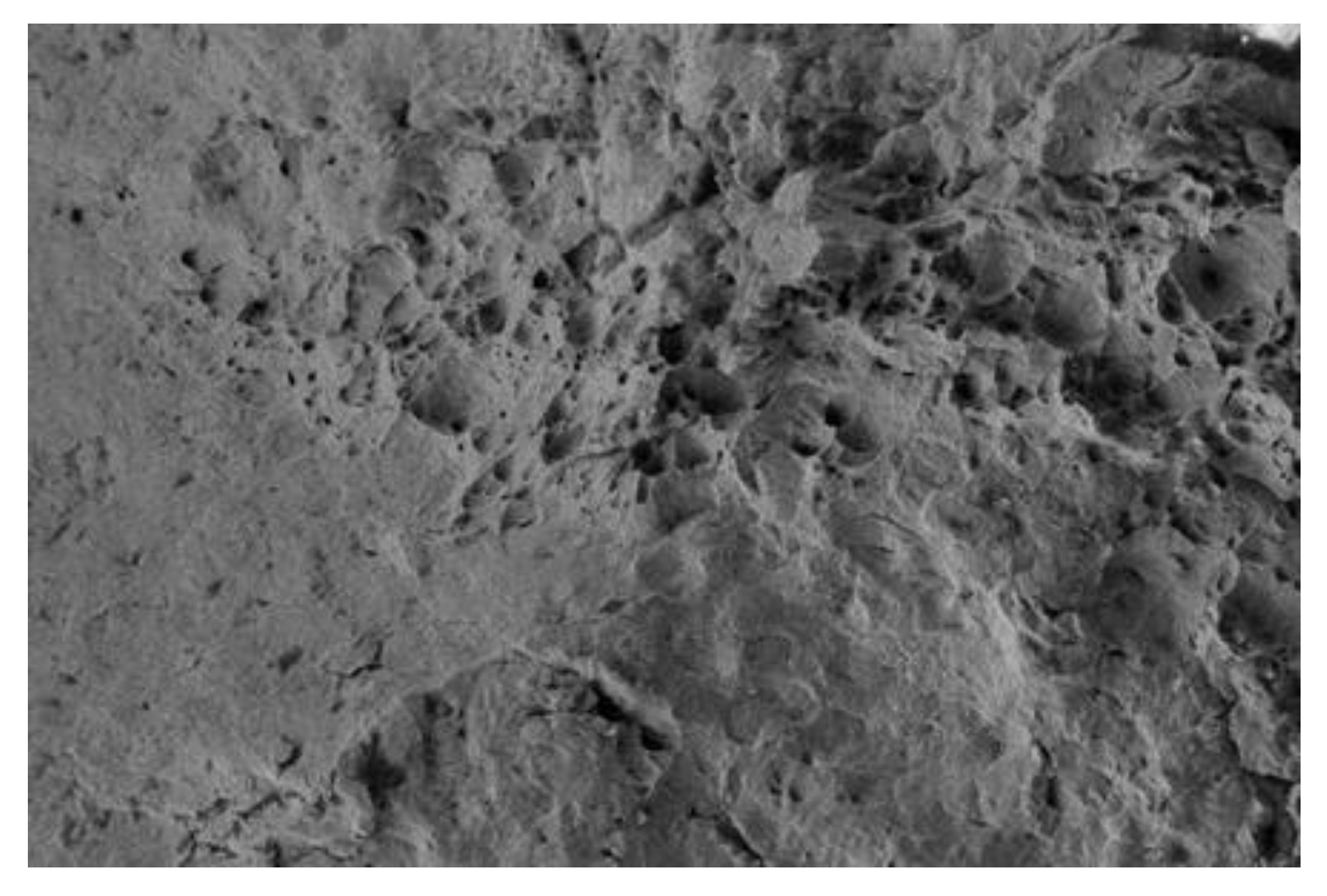
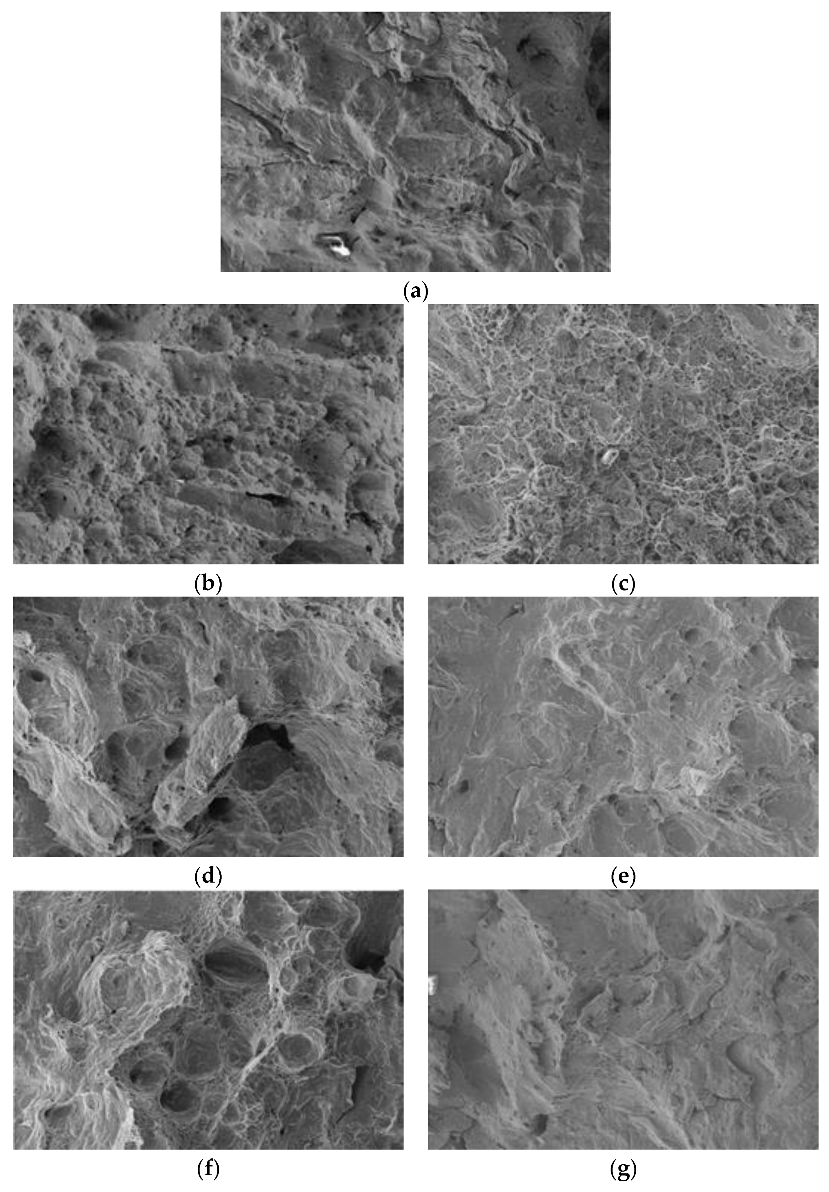
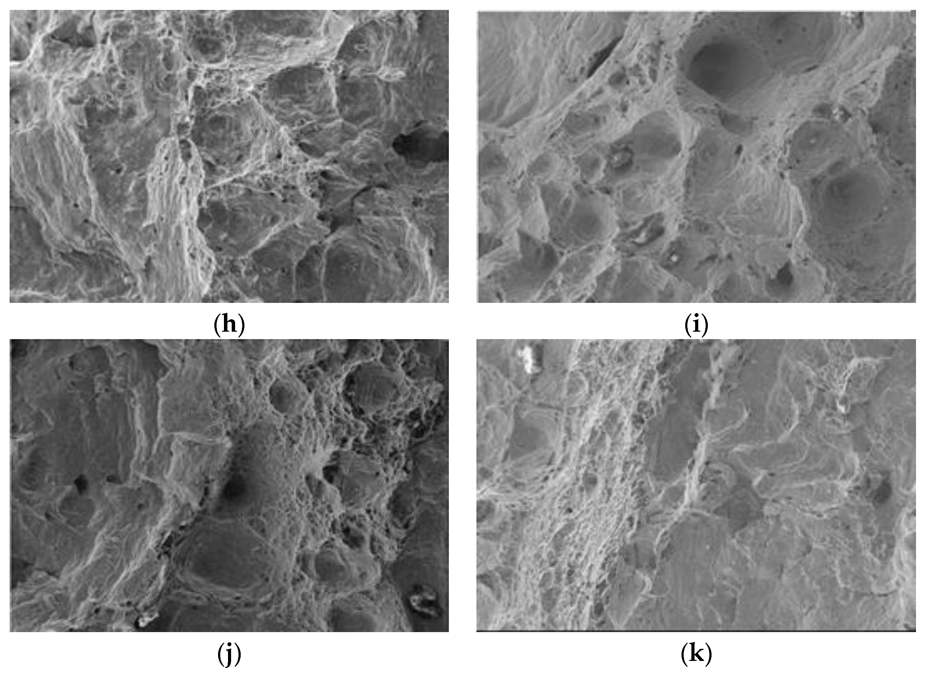
3.3. Analysis of Fracture Morphology

Figure 11 shows the fracture morphology of 304 stainless steel specimens after 43 bending cycles. In the early stage of bending cycles, significant deformation occurs on both sides of the specimen due to stress, which can cause plastic slip and lattice distortion. Crack sources are formed under concentrated stress, and internal defects in the material also form crack sources under stress. The initiation area of fatigue cracks usually grows relatively slowly. Under the continuous bending cyclic deformation, the areas near the cracks rub against each other to form a relatively flat crack propagation zone. As the crack propagates, the remaining area is insufficient to bear the maximum stress, resulting in the formation of an instantaneous fracture zone. A large number of ductile dimples are distributed in the instantaneous fracture zone of 304 stainless steel, and the fracture property is ductile fracture.
Figure 12 shows the fracture morphology of Fe-Mn-Si shape memory alloy specimens treated with different solid solution conditions after bending cycles until fracture. During the bending cycle, the Fe-Mn-Si shape memory alloy also forms a relatively flat crack propagation zone due to the continuous expansion of the crack source, until the remaining area is insufficient to withstand the occurrence of fracture, forming an instantaneous fracture zone. The fracture area is mainly characterized by ductile fracture, with some areas exhibiting quasi-cleavage fracture characteristics.

4. Conclusions

(1) When the strain is ±5%, the number of bending cycles until fracture of Fe-Mn-Si shape memory alloy specimens without solid solution treatment is 221. The number of bending cycles until fracture of 304 stainless steel under the same test conditions is 43. Experiments have shown that Fe-Mn-Si shape memory alloys have excellent bending fatigue performance. The number of bending cycles until fracture of Fe-Mn-Si shape memory alloy specimens treated with solid solution increased, reaching a maximum of 511 under the condition of 850 °C solid solution treatment for 1 h. The number of bending cycles until fracture increased by 131% compared to untreated specimens.
(2) During the bending cycle, the Fe-Mn-Si shape memory alloy specimen underwent reversible γε martensitic transformation, while the 304 stainless steel specimen underwent γα′ martensitic transformation. When subjected to external cyclic stress, Fe-Mn-Si shape memory alloys adapt to changes in macroscopic stress-induced γε martensitic transformation and its reverse transformation, thereby reducing the peak stress inside the material, reducing stress concentration, delaying the propagation of fatigue cracks, and improving its fatigue life.
(3) The fracture area of Fe-Mn-Si shape memory alloy specimens is mainly characterized by ductile fracture, with some areas exhibiting quasi-cleavage fracture. The fracture area of 304 stainless steel specimens is mainly characterized by ductile fracture.

Author Contributions

Conceptualization, C.L. and H.N.; methodology, C.L. and H.N.; software, H.N.; validation, H.N. and Y.S.; formal analysis, H.N.; investigation, H.N.; resources, C.L.; data curation, Y.S.; writing—original draft preparation, H.N.; writing—review and editing, C.L. and Y.S.; visualization, Y.S.; supervision, C.L.; project administration, C.L.; funding acquisition, C.L. All authors have read and agreed to the published version of the manuscript.

Funding

This research was funded by the National Natural Science Foundation of China, grant number 52378177.

Data Availability Statement

The original contributions presented in the study are included in the article, further inquiries can be directed to the corresponding author.

Conflicts of Interest

The authors declare no conflicts of interest.

References

  1. Zhang, Z.X.; Zhang, J.; Wu, H.L.; Ji, Y.Z.; Kumar, D. Iron-Based Shape Memory Alloys in Construction: Research, Applications and Opportunities. Materials 2022, 15, 1723. [Google Scholar] [CrossRef] [PubMed]
  2. Pan, M.M.; Zhang, X.M.; Zhou, D.; Misra, R.D.K.; Chen, P.; Su, X.B. On the significance of C and Co on shape memory performance of Fe-Mn-Si-Cr-Ni shape memory alloy. Mater. Sci. Eng. A-Struct. 2020, 786, 139412. [Google Scholar] [CrossRef]
  3. Koyama, M.; Sawaguchi, T.; Tsuzaki, K. Si content dependence on shape memory and tensile properties in Fe-Mn-Si-C alloys. Mater. Sci. Eng. A-Struct. 2011, 528, 2882–2888. [Google Scholar] [CrossRef]
  4. Ariapour, A.; Yakubtsov, I.; Perovic, D.D. Shape-memory effect and strengthening mechanism in a Nb and N-doped Fe-Mn-Si-based alloy. Metall. Mater. Trans. A 2001, 32, 1621–1628. [Google Scholar] [CrossRef]
  5. Stanford, N.; Dunne, D.P. Thermo-mechanical processing and the shape memory effect in an Fe-Mn-Si-based shape memory alloy. Mater. Sci. Eng. A-Struct. 2006, 422, 352–359. [Google Scholar] [CrossRef]
  6. Lin, H.C.; Lin, K.M.; Wu, S.K.; Wang, T.P.; Hsiao, Y.C. Effects of thermo-mechanical training on a Fe59Mn30Si6Cr5 shape memory alloy. Mater. Sci. Eng. A-Struct. 2006, 438, 791–795. [Google Scholar] [CrossRef]
  7. Leinenbach, C.; Kramer, H.; Bernhard, C.; Eifler, D. Thermo-Mechanical Properties of an Fe-Mn-Si-Cr-Ni-VC Shape Memory Alloy with Low Transformation Temperature. Adv. Eng. Mater. 2012, 14, 62–67. [Google Scholar] [CrossRef]
  8. Yang, C.H.; Lin, H.C.; Lin, K.M.; Tsai, H.K. Effects of thermo-mechanical treatment on a Fe-30Mn-6Si shape memory alloy. Mater. Sci. Eng. A-Struct. 2008, 497, 445–450. [Google Scholar] [CrossRef]
  9. Koyama, M.; Sawaguchi, T.; Ogawa, K.; Kikuchi, T.; Murakami, M. The effects of thermomechanical training treatment on the deformation characteristics of Fe-Mn-Si-Al alloys. Mater. Sci. Eng. A-Struct. 2008, 497, 353–357. [Google Scholar] [CrossRef]
  10. Lai, M.J.; Li, Y.J.; Lillpopp, L.; Ponge, D.; Will, S.; Raabe, D. On the origin of the improvement of shape memory effect by precipitating VC in Fe-Mn-Si-based shape memory alloys. Acta Mater. 2018, 155, 222–235. [Google Scholar] [CrossRef]
  11. Peng, H.; Chen, J.; Wang, Y.; Wen, Y. Key Factors Achieving Large Recovery Strains in Polycrystalline Fe-Mn-Si-Based Shape Memory Alloys: A Review. Adv. Eng. Mater. 2018, 20, 1700741. [Google Scholar] [CrossRef]
  12. Megdiche, M.; Sallami, A.; Thiébaud, F.; Bouraoui, T.; Ben Zineb, T.; Chirani, S.A. Experimental analysis of the pseudoelastic damping capacity of the Fe-30Mn-6Si-5Cr Shape Memory Alloy. Smart Mater. Struct. 2020, 29, 084002. [Google Scholar] [CrossRef]
  13. Fang, C.; Liang, D.; Zheng, Y.; Lu, S. Seismic performance of bridges with novel SMA cable-restrained high damping rubber bearings against near-fault ground motions. Earthq. Eng. Struct. Dyn. 2022, 51, 44–65. [Google Scholar] [CrossRef]
  14. Fang, C.; Liang, D.; Zheng, Y.; Yam, M.C.H.; Sun, R. Rocking bridge piers equipped with shape memory alloy (SMA) washer springs. Eng. Struct. 2020, 214, 110651. [Google Scholar] [CrossRef]
  15. Liang, D.; Zheng, Y.; Fang, C.; Yam, M.C.H.; Zhang, C. Shape memory alloy (SMA)-cable-controlled sliding bearings: Development, testing, and system behavior. Smart Mater. Struct. 2020, 29, 085006. [Google Scholar] [CrossRef]
  16. Khaili, A.; Elkafrawy, M.; Abuzaid, W.; Hawileh, R.; AlHamaydeh, M. Flexural Performance of RC Beams Strengthened with Pre-Stressed Iron-Based Shape Memory Alloy (Fe-SMA) Bars: Numerical Study. Buildings 2022, 12, 2228. [Google Scholar] [CrossRef]
  17. Dolatabadi, N.; Shahverdi, M.; Ghassemieh, M.; Motavalli, M. RC Structures Strengthened by an Iron-Based Shape Memory Alloy Embedded in a Shotcrete Layer-Nonlinear Finite Element Modeling. Materials 2020, 13, 5504. [Google Scholar] [CrossRef] [PubMed]
  18. Yeon, Y.M.; Hong, K.N.; Ji, S.W. Flexural Behavior of Self-Prestressed RC Slabs with Fe-Based Shape Memory Alloy Rebar. Appl. Sci. 2022, 12, 1640. [Google Scholar] [CrossRef]
  19. Pricop, B.; Söyler, A.U.; Özkal, B.; Bujoreanu, L. Powder Metallurgy: An Alternative for FeMnSiCrNi Shape Memory Alloys Processing. Front. Mater. 2020, 7, 247. [Google Scholar] [CrossRef]
  20. Popa, M.; Mihalache, E.; Cojocaru, V.D.; Gurau, C.; Gurau, G.; Cimpoe¸su, N.; Pricop, B.; Comaneci, R.-I.; Vollmer, M.; Krooß, P. Effects of Thermomechanical Processing on the Microstructure and Mechanical Properties of Fe-Based Alloys. J. Mater. Eng. Perform. 2020, 29, 2274–2282. [Google Scholar] [CrossRef]
  21. Nikulin, I.; Sawaguchi, T.; Yoshinaka, F.; Takamori, S. Influence of cold rolling deformation mechanisms on the grain refinement of Fe-15Mn-10Cr-8Ni-4Si austenitic alloy. Mater. Charact. 2020, 162, 110191. [Google Scholar] [CrossRef]
  22. Yoshinaka, F.; Sawaguchi, T. Characterization of crystallographic fracture surfaces in Fe-33Mn-6Si alloy. Int. J. Fatigue 2020, 130, 105271. [Google Scholar] [CrossRef]
  23. Gu, X.L.; Chen, Z.Y.; Yu, Q.Q.; Ghafoori, E. Stress recovery behavior of an Fe-Mn-Si shape memory alloy. Eng. Struct. 2021, 243, 112710. [Google Scholar] [CrossRef]
  24. Wang, B.; Zhu, S. Cyclic behavior of iron-based shape memory alloy bars for high-performance seismic devices. Eng. Struct. 2021, 252, 113588. [Google Scholar] [CrossRef]
  25. Gu, T.; Jia, L.J.; Chen, B.; Xia, M.; Guo, H.; He, M.C. Unified full-range plasticity till fracture of meta steel and structural steels. Eng. Fract. Mech. 2021, 253, 107869. [Google Scholar] [CrossRef]
  26. Rosa, D.I.H.; Hartloper, A.; Sousa, A.D.C.E.; Lignos, D.G.; Motavalli, M.; Ghafoori, E. Experimental behavior of iron-based shape memory alloys under cyclic loading histories. Constr. Build. Mater. 2021, 272, 121712. [Google Scholar] [CrossRef]
  27. Cladera, A.; Weber, B.; Leinenbach, C.; Czaderski, C.; Shahverdi, M.; Motavalli, M. Iron-based shape memory alloys for civil engineering structures: An overview. Constr. Build. Mater. 2014, 63, 281–293. [Google Scholar] [CrossRef]
  28. Sawaguchi, T.; Sahu, P.; Kikuchi, T.; Ogawa, K.; Kajiwara, S.; Kushibe, A.; Higashino, M.; Ogawa, T. Vibration mitigation by the reversible fcc/hcp martensitic transformation during cyclic tension compression loading of an Fe-Mn-Si-based shape memory alloy. Scr. Mater. 2006, 54, 1885–1890. [Google Scholar] [CrossRef]
  29. Sawaguchi, T.; Nikulin, I.; Ogawa, K.; Sekido, K.; Takamori, S.; Maruyama, T.; Chiba, Y.; Kushibe, A.; Inoue, Y.; Tsuzaki, K. Designing Fe-Mn-Si alloys with improved low-cycle fatigue lives. Scr. Mater. 2015, 99, 49–52. [Google Scholar] [CrossRef]
  30. Koster, M.; Lee, W.J.; Schwarzenberger, M.; Leinenbach, C. Cyclic deformation and structural fatigue behavior of an Fe-Mn-Si shape memory alloy. Mater. Sci. Eng. A-Struct. 2015, 637, 29–39. [Google Scholar] [CrossRef]
  31. Ghafoori, E.; Neuenschwander, M.; Shahverdi, M.; Czaderski, C.; Fontana, M. Elevated temperature behavior of an iron-based shape memory alloy used for prestressed strengthening of civil structures. Constr. Build. Mater. 2019, 211, 437–452. [Google Scholar] [CrossRef]
  32. Ghafoori, E.; Hosseini, E.; Leinenbach, C.; Michels, J.; Motavalli, M. Fatigue behavior of a Fe-Mn-Si shape memory alloy used for prestressed strengthening. Mater. Des. 2017, 133, 349–362. [Google Scholar] [CrossRef]
  33. Qiu, C.X.; Zhang, A.F.; Jiang, T.Y.; Du, X.L. Seismic performance analysis of multi-story steel frames equipped with FeSMA BRBs. Soil Dyn. Earthq. Eng. 2022, 161, 107392. [Google Scholar] [CrossRef]
  34. Zhang, J.; Fang, C.; Yam, M.C.H.; Lin, C. Fe-Mn-Si alloy U-shaped dampers with extraordinary low-cycle fatigue resistance. Eng. Struct. 2022, 264, 114475. [Google Scholar] [CrossRef]
  35. Wang, W.; Fang, C.; Ji, Y.; Lu, Y.; Yam, M.C.H. Experimental and Numerical Studies on Fe–Mn–Si Alloy Dampers for Enhanced Low-Cycle Fatigue Resistance. J. Struct. Eng. 2022, 148, 04022170. [Google Scholar] [CrossRef]
  36. Zhang, Z.; Fang, C.; He, Q.; Li, Y.; Liao, F.; Ji, Y. Fracture prediction of Fe-SMA under monotonic and low cycle fatigue loading. Int. J. Fatigue 2023, 175, 107794. [Google Scholar] [CrossRef]
  37. Inoue, Y.; Kushibe, A.; Umemura, K.; Mizushima, Y.; Sawaguchi, T.; Nakamura, T.; Otsuka, H.; Chiba, Y. Fatigue-resistant Fe-Mn-Si-based alloy seismic dampers to counteract long-period ground motion. Jpn. Archit. Rev. 2020, 4, 76–87. [Google Scholar] [CrossRef]
  38. Fang, C.; Wang, W.; Ji, Y.; Yam, M.C.H. Superior low-cycle fatigue performance of iron-based SMA for seismic damping application. J. Constr. Steel. Res. 2021, 184, 106817. [Google Scholar] [CrossRef]
  39. Sawaguchi, T.; Maruyama, T.; Otsuka, H.; Kushibe, A.; Inoue, Y.; Tsuzaki, K. Design Concept and Applications of Fe-Mn-Si-Based Alloys-from Shape-Memory to Seismic Response Control. Mater. Trans. 2016, 57, 283–293. [Google Scholar] [CrossRef]
Figure 1. Size of bending cycle fatigue specimen.
Metals 14 00441 g001
Figure 2. The principle of the bending cycle test.
Metals 14 00441 g002
Figure 3. The number of bending cycles until fracture of Fe-Mn-Si shape memory alloy with solid solution treatment temperature variation.
Metals 14 00441 g003
Figure 4. XRD pattern of 304 stainless steel after bending cycle fracture.
Metals 14 00441 g004
Figure 5. XRD patterns of Fe-Mn-Si shape memory alloy specimens with solid solution treatment for 1 h after fracture.
Metals 14 00441 g005
Figure 6. Volume fraction of phases in Fe-Mn-Si shape memory alloy specimens with solid solution treatment for 1 h after fracture.
Metals 14 00441 g006
Figure 7. XRD patterns of Fe-Mn-Si shape memory alloy specimens with solid solution treatment for 3 h after fracture.
Metals 14 00441 g007
Figure 8. Volume fraction of phases in Fe-Mn-Si shape memory alloy specimens with solid solution treatment for 3 h after fracture.
Metals 14 00441 g008
Figure 9. XRD patterns of Fe-Mn-Si shape memory alloy specimens after different bending cycles.
Metals 14 00441 g009
Figure 10. Volume fraction of phases in Fe-Mn-Si shape memory alloy specimens after different bending cycles.
Metals 14 00441 g010
Figure 11. The fracture morphology of 304 stainless steel specimens.
Metals 14 00441 g011
Figure 12. The fracture morphology of Fe-Mn-Si shape memory alloy specimens (500×): (a) untreated; (b) 750 °C, 1 h; (c) 750 °C, 3 h; (d) 850 °C, 1 h; (e) 850 °C, 3 h; (f) 950 °C, 1 h; (g) 950 °C, 3 h; (h) 1050 °C, 1 h; (i) 1050 °C, 3 h; (j) 1150 °C, 1 h; and (k) 1150 °C, 3 h.
Metals 14 00441 g012aMetals 14 00441 g012b
Table 1. Chemical composition and mass fraction of Fe-Mn-Si shape memory alloy.
Chemical ElementMnSiCrNiFe
Mass fraction/%17.644.4610.355.03Bal.
Table 2. The number of bending cycles until fracture of Fe-Mn-Si shape memory alloy.
Solid Solution TreatmentUntreated750 °C850 °C950 °C1050 °C1150 °C
1 h3 h1 h3 h1 h3 h1 h3 h1 h3 h
Number of cycles221281276511486463441429379373351
Disclaimer/Publisher’s Note: The statements, opinions and data contained in all publications are solely those of the individual author(s) and contributor(s) and not of MDPI and/or the editor(s). MDPI and/or the editor(s) disclaim responsibility for any injury to people or property resulting from any ideas, methods, instructions or products referred to in the content.

