Communication

Atomic-Scale Insights into Flow-Accelerated Corrosion of Carbon Steel

1
Materials Safety Research Division, Korea Atomic Energy Research Institute, Daejeon 34057, Republic of Korea
2
Department of Materials Science and Engineering, Yonsei University, Seoul 03722, Republic of Korea
*
Author to whom correspondence should be addressed.
These authors contributed equally to this work.
Metals 2024, 14(4), 445; https://doi.org/10.3390/met14040445
Submission received: 8 March 2024 / Revised: 8 April 2024 / Accepted: 10 April 2024 / Published: 11 April 2024
(This article belongs to the Special Issue Passivity and Localized Corrosion of Metallic Materials)

Abstract

:
The role of flow velocity on the formation and dissolution of oxides on SA106Gr.B carbon steel was investigated at both microscopic and atomic scales. In static water, a compact oxide layer with highly faceted magnetite particles was formed. Atomic-scale transmission electron microscopy images of such a layer revealed highly ordered and parallel lattice fringes, indicating that the oxide had very high crystallinity and minimal lattice defects. In contrast, turbulent water prompted the creation of a porous oxide layer consisting of amorphous magnetite particles. Here, numerous mismatched lattice fringes were observed, indicating a prevalence of point defects within the oxide structure. These differences in oxide properties are attributed to hydrodynamic shear stress induced by turbulent flow. These findings provide atomic-level insights into how carbon steel corrosion accelerates in fast-flowing water.

1. Introduction

Carbon steel, commonly used as a piping material in nuclear plants, undergoes accelerated corrosion under fast-flowing single-phase water and two-phase water–steam conditions. This damage mode is well known as flow-accelerated corrosion (FAC), and major factors affecting FAC have been extensively investigated and established [1,2,3]. The key mechanism of FAC involves the accelerated dissolution of an oxide layer at the oxide/water interface due to fluid velocity, coupled with the formation of oxide at the metal/oxide interface through base metal corrosion, resulting in wall thinning (metal loss) of the piping. It can therefore be seen that inhibiting the dissolution of the oxide film is an important means of alleviating FAC. Magnetite (Fe3O4) typically constitutes the oxide that is formed on carbon steel in reducing water environments. Furthermore, the FAC rate of carbon steel is at its minimum near the pH where the solubility of magnetite is lowest [4,5,6]. The addition of chromium to carbon steel drastically reduces FAC, with benefits realized even with a chromium content as low as 0.1–4 wt.% [7,8,9,10]. This result is attributed to the integration of chromium into the magnetite film, reducing its solubility.
Therefore, there is a recognized need for extensive research into the characteristics of oxides, particularly since the atomic-scale characteristics of oxide films remain largely unexplored. Most studies have relied on weight loss to evaluate FAC behavior, and have largely focused on the surface morphology of oxide films, if addressed at all. In other words, porous oxides have been observed from top-down view images of carbon steel exposed to flowing water [11,12,13]. However, the true morphological nature of oxide films can be fully grasped only when accompanied with cross-sectional observations. Many researchers have stated that oxide films formed under FAC conditions are porous without providing their own experimental evidence. These arguments originate from the following two studies: Castle and Mann [14] proposed that pores originate from the partial dissolution of the corroded surface during the early stages of oxidation, while Berge et al. [15] showed that a porous oxide layer forms due to the outward diffusion of hydrogen produced during magnetite formation in the solution. However, these results were obtained from experiments conducted in a static 13% NaOH solution, not in flowing water.
In summary, previous studies on FAC have focused on the effects of material, water chemistry, and geometric factors on the corrosion rate (i.e., weight loss), almost all of which have been carried out at a constant flow rate or under various flow rate conditions. Furthermore, so far no one has ever observed the cross-section of the oxide films formed in the presence and absence of water flow at the atomic scale using TEM. There are no studies even on the differences in the morphology of the surface and cross-sections of the oxides formed in static and fast-flowing water. The differing nature of oxides formed during the corrosion of carbon steel in static versus fast-flowing water is crucial, in that it can provide insights into how fluid flow plays a role in the formation and dissolution of oxide films.
In this study, we systemically examined oxide films formed under both static and dynamic water flow conditions using scanning electron microscopy (SEM) and high-angle annular dark-field (HAADF) scanning transmission electron microscopy (STEM). To the best of our knowledge, no attempts to interpret FAC behavior from this viewpoint have been undertaken in previous research.

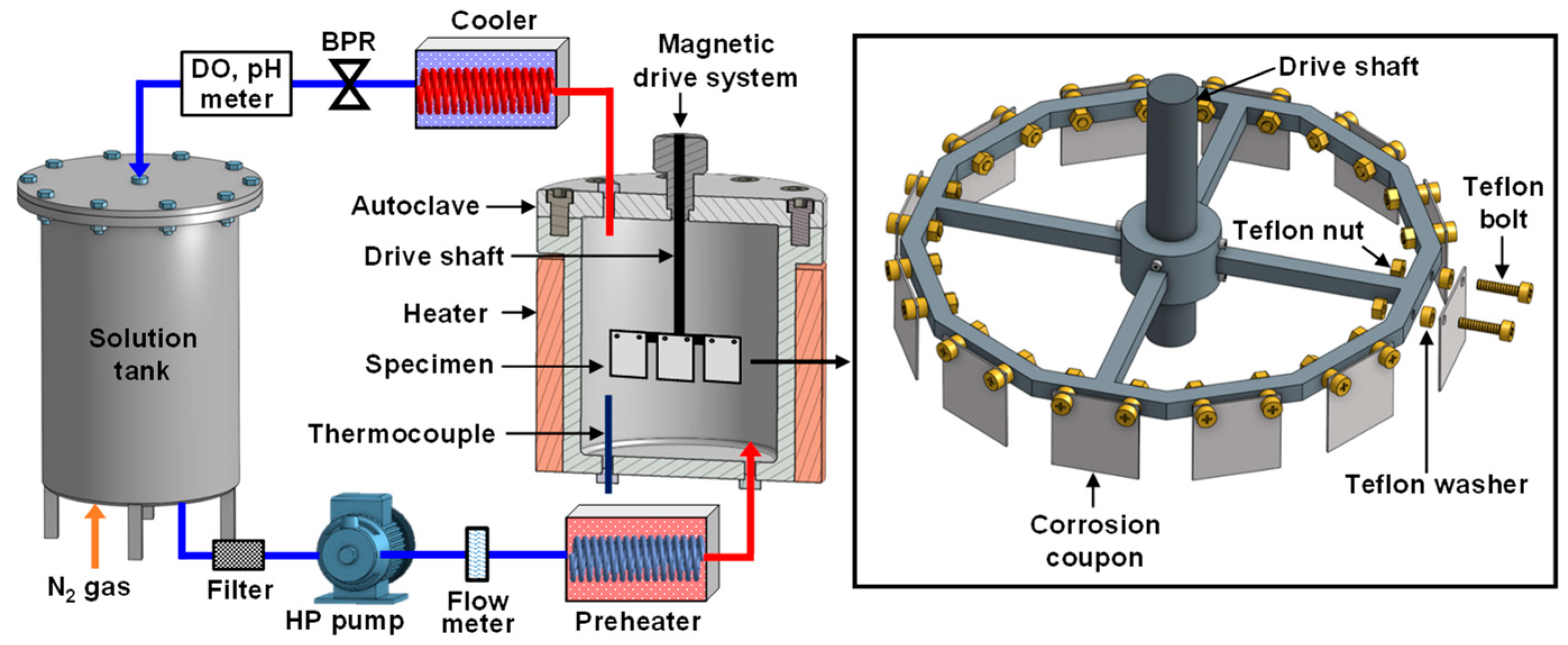
2. Materials and Methods

Specimens were prepared by cutting SA106 Gr.B carbon steel using wire-cutting electrical discharge machining. The dimensions of the specimens were 25 × 25 × 1 mm3. The chemical composition of the carbon steel is given in Table 1. The specimen surfaces were ground using SiC paper to a grit size of #1000, and then ultrasonically cleaned in acetone.
Figure 1 shows the closed water circulation system used for corrosion testing. This system consisted of a solution tank, a high-pressure circulation pump, a preheater, a 316 L stainless steel autoclave, a cooler, and pH and dissolved oxygen sensors for solution chemistry monitoring. Deionized water was poured into the solution make-up tank, and the solution pH was controlled at 9.0 at ~23 °C by adding NH4OH as a pH control agent. Nitrogen gas was bubbled through the solution so that the level of dissolved oxygen was maintained below 2 μg/L. This solution chemistry is similar to that of secondary feed-water in nuclear power plants [16].
As shown in Figure 1, corrosion coupons were fixed in a regular dodecagonal-shaped specimen holder made of 316 L stainless steel, with Teflon bolts and nuts. Teflon washers were used to prevent galvanic coupling between the coupons and the holder. The specimen holder was attached to the drive shaft of a magnetic drive assembly that was mounted on the lid of the autoclave with a volume of 4 L. The distance between the drive shaft axis and the coupon was 7.25 cm. The solution entered the test section at a flow rate of 0.15 L/min at 20 bars via the high-pressure pump, while the effluent solution returned to the solution reservoir via the cooler, the pH sensor, and the dissolved oxygen sensor. The temperature of the solution adjacent to the coupons in the test section was maintained at 150 °C.
When these conditions were satisfied, two types of corrosion tests were performed separately. First, the drive shaft was rotated using the magnetic drive mechanism so that the water flow velocity at the surface of the corrosion coupons was 5 m/s, which was calculated from the angular velocity. Second, a corrosion test was performed without rotating the magnetic drive. In this case, the circulating water flow rate of 0.15 L/min corresponded to a flow velocity of 9.3 × 10⁻⁵ m/s in the test section, considering the inner diameter (18.5 cm) of the autoclave. Therefore, the second test condition can be regarded as a static fluid condition (0 m/s). The tests were conducted for 500 h each. Upon completion of each test, the corrosion coupons were carefully removed from the specimen holder and cleaned with deionized water and acetone. The corrosion coupons were weighed using a balance with an accuracy of 10−5 g.
The outer surfaces covered with oxides grown during the corrosion tests were examined using SEM. The oxide films were vertically cross-sectioned using a focused-gallium ion beam (FIB) at an accelerating voltage of 30 keV and subsequently observed via SEM. A platinum layer was coated on the area of interest to prevent sputter damage before milling.
Cross-sectional foils for transmission electron microscopy (TEM) analysis were made by milling the oxide films using the FIB technique. The images and diffraction patterns of the oxides were examined using TEM at an acceleration voltage of 200 kV. The chemical compositions of the oxides were also examined using energy-dispersive spectroscopy (EDS) built into the TEM.

3. Results

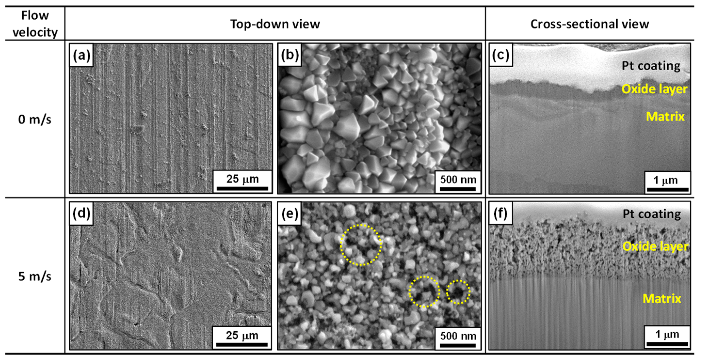
3.1. Corrosion Behavior and Oxide Layer Characteristics

The corrosion rate of the corrosion coupons was measured by analyzing the weight loss data after the 500 h corrosion test. Under static water conditions, the corrosion rate was 0.44 μg/cm2h. However, under dynamic water conditions at 5 m/s, the corrosion rate drastically accelerated to 5.20 μg/cm2h, approximately 12 times higher. This result, although expected, demonstrates why this phenomenon is designated as FAC.
Figure 2 shows the surface and cross-section SEM micrographs of the specimens corroded in static and dynamic water, revealing distinct morphological differences. Under static water conditions, abrasive marks from the silicon carbide paper remained intact on the original surface of the specimens (Figure 2a). When viewed at high magnification, the surface was densely covered with polyhedral-shaped particles, each measuring less than approximately 400 nm (Figure 2b). Additionally, a compact and thin oxide layer was observed on the cross-section of the specimens (Figure 2c). In contrast, most of the abrasive marks were not observed under the fast flow conditions (Figure 2d), indicating removal of the original surface due to accelerated corrosion. Oxide particles on the specimen surface were significantly refined to less than approximately 100 nm (Figure 2e). The particles displayed very irregular, crumb-like shapes without a defined or multi-faceted shape. Moreover, the particles exhibited a loose arrangement, with microscopic voids discernable, as marked by the yellow circles. These results indicate that oxides formed in turbulent water exhibit lower adhesion compared to those formed in static water. Furthermore, the cross-section of the sample clearly showed that the oxide layer was very porous (Figure 2f). For convenience, the oxides formed under static (0 m/s) and fast (5 m/s) water flow conditions are referred to as static and dynamic oxides, respectively, in this study.
Figure 3 shows the STEM micrographs and selected area electron diffraction (SAED) patterns of cross-sectional oxide films formed under the two different conditions. In the static oxide, the oxide layer was very dense in the thickness direction, with some voids observable at the outer layer (Figure 3a). Considering the particle size, morphology, and distribution shown in Figure 2b, it is likely that these voids originated from interstices between polyhedral oxide particles, rather than actual pores inside the oxide film matrix. Conversely, under the fast water conditions, the porous aspect was more pronounced throughout the entire oxide thickness, with porosity escalating from the metal/oxide interface to the oxide/solution interface (Figure 3c). Both oxides were identified as magnetite via EDS point analyses. The SAED patterns of both oxides showed ring patterns with bright spots (Figure 3b,d), demonstrating that the oxides are polycrystalline in nature. The d-spacings matched perfectly with the cubic spinel Fe3O4 (JCPDS No. 19-0629).

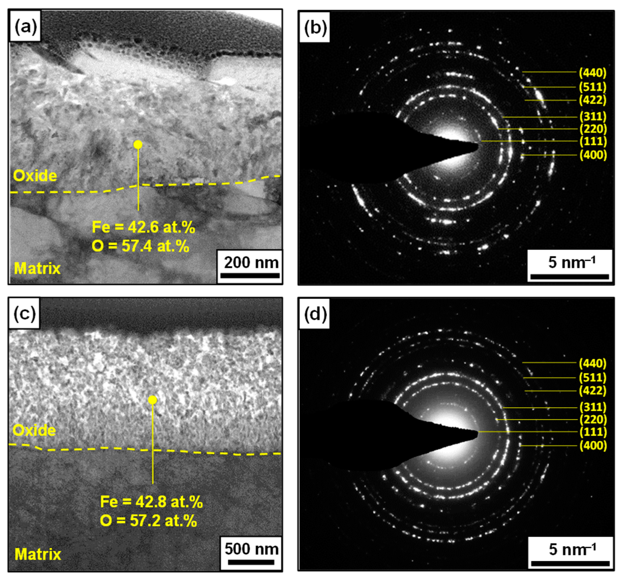
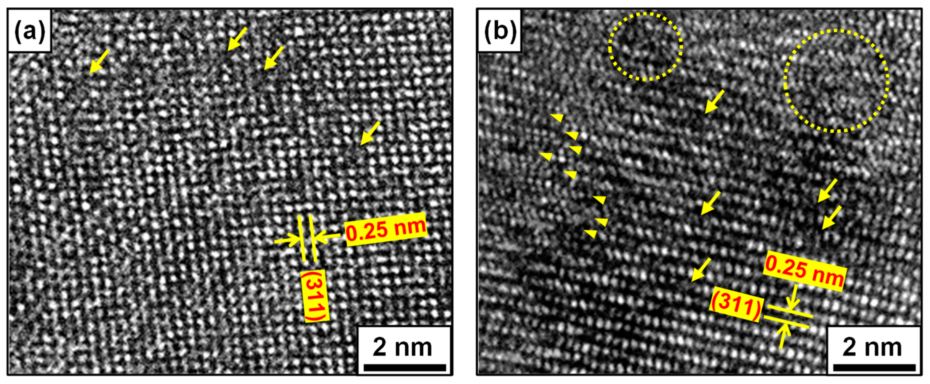
3.2. Atomic-Scale Oxide Structure

Lattice fringes have been used to study atomic structures and to identify crystal defects in materials [17,18,19,20,21]. To directly observe the lattice fringes and lattice imperfections within the oxides at the atomic scale, we examined high-resolution TEM micrographs of the oxides. Figure 4 displays the HAADF-STEM micrographs of the oxides grown under static and fast-flowing water conditions. The micrographs of the static films showed a lattice fringe spacing of 0.25 nm (Figure 4a), corresponding to the (311) plane of cubic Fe3O4. These lattice fringes were distinct, highly ordered, and parallel, indicating that the oxide has very high crystallinity and the lattice planes have few crystal defects. Nevertheless, some localized spots with blurred lattice fringes were observed, as denoted by the yellow arrows, indicating the existence of vacancy-type defects at these sites. In the dynamic oxides (Figure 4b), well-defined lattice fringes with 0.25 nm spacing were also observed, although some blurred spots were present, as indicated by the yellow arrows. However, the lattice fringes revealed much more obscure and discontinuous characteristics, as marked by the arrow heads. Slightly disordered regions were also observed, as indicated by the dotted circles. These discontinuous lattice fringes are attributed to dislocations [22,23,24], indicating the presence of abundant defects at these sites. Therefore, this result demonstrates that the dynamic oxide film is highly defective at the atomic scale.

4. Discussion

The Reynolds Number (Re) can be estimated by the following equation:
Re = VD/υ
where V is the velocity of the fluid flow (m/s), D is the diameter of the cylinder (m), and υ is the kinematic viscosity (m2/s). The kinematic viscosity of water at 150 °C is 1.78 × 10⁻⁷ m2/s, which was calculated using the Yetilmezsoy model [25]. In this work, V is 5 m/s, and D is 0.145 m. Therefore, the Re is calculated to be 4.07 × 10⁶ in the dynamic flow conditions of this study. In general, a turbulent flow occurs at Re > 4000 [26], confirming that the corrosion test was performed under a completely turbulent condition. Turbulent flow increases shear stress as well as mass transfer on the specimen surface. As a result, turbulent flow water leads to severe corrosion of carbon steel piping, resulting in expensive plant repairs and even causing serious personnel injuries in nuclear power plants, as discussed in the literature [27,28]. Shear stress (τ) exerted on the surface by the fluid is directly proportional to the square of the fluid velocity, as follows:
τ = 1 8 ρ f V 2
where ρ is the density of the fluid (kg/m3), and f is the Darcy friction factor (f = 4.16 × 10⁻² in this study). The calculated shear stress was 119 Pa under the test conditions of this study.
The evolution of metal and oxide crystal morphology during crystal growth is in principle driven by the continuous reduction of the total surface energy of the crystal. Consequently, facets appear at low-indexed crystallographic planes with lower surface energy [29,30,31]. In static water, metal oxidation proceeds under stable or equilibrium conditions, characterized by a low corrosion rate and a gradual concentration gradient. Therefore, crystal facets with lower surface energy will predominantly be developed. As a result, a compact oxide layer with highly faceted particles on the outer surface is formed (Figure 2b,c).
In turbulent water, the concentration of iron ions at the oxide/water interface is high due to the high corrosion rate of the oxide. The thickness of the boundary layer also decreases due to the fast water flow [32,33,34]. Therefore, it is evident that the concentration or chemical potential gradient of iron ions across the boundary layer becomes steep in turbulent water. Therefore, oxides in turbulent flows grow under conditions with both high corrosion rates and steep concentration gradients. Under such circumstances, faceted growth can be disturbed by hydrodynamic shear forces generated by turbulent flow. In reality, 3D calculations have shown that the curvature of faceted interfaces decreases with increasing external forces during crystal growth [35]. In this study, the corrosion rate in turbulent water was 12 times higher than in static water. Therefore, the fast dissolution rate of the oxide film at the oxide/water interface is another reason why the outer oxide has an irregular and crumb-like shape. These phenomena can lead to the formation of amorphous particles lacking well-developed facets in turbulent flow conditions. Therefore, a defective and porous oxide layer forms on the outer surface due to the effects of mass transfer and shear stress, as discussed above (Figure 2e,f). It is well known that the mass transfer coefficient is correlated with fluid velocity [36]. In addition, turbulent flow decreases the boundary layer thickness [33,34]. Consequently, the transport of dissolved iron ions is promoted from the oxide surface into the bulk water under turbulent water conditions. In this study, a 12-fold increase in corrosion rate serves as evidence for this transport phenomenon. Such a porous oxide layer fails to protect carbon steel from corrosion when exposed to turbulent flows.
In situ atomic-scale observations have shown that oxidation proceeds via the atomic layer-by-layer growth mechanism [37,38,39,40]. In the course of magnetite formation, iron and oxygen ions are first delivered onto the surface of the basal layer by diffusion from the matrix and the water, respectively. Subsequently, these ions combine to form magnetite molecules. At this stage, because iron ions, oxygen ions, and magnetite molecules are mobile on the surface, shear stress induced by turbulent flow can distort the atomic arrangement of newly formed magnetite molecules. The mismatched aspects of the oxide lattice fringes observed in Figure 4b cannot be explained by the fast dissolution and mass transfer effects. Therefore, the origin of these characteristics is attributed to the shear stress exerted on the growing magnetite layers.
Meanwhile, it is commonly accepted that the outer oxide layer grows through precipitation from the solution [41,42]. Under our test conditions, the precipitation of Fe3O4 crystals from dissolved iron ions might occur via the following reactions:
Fe2+ + 2OH = Fe(OH)2 (ΔG150°C = −120.97 kJ/mol)
3Fe(OH)2 = Fe3O4 + 2H2O + H2 (ΔG150°C = −30.98 kJ/mol)
The Gibbs free energy of each reaction was calculated using HSC Chemistry 6 software (version 6.12) [43]. Thermodynamic calculations show that the reactions can occur spontaneously. However, in severe turbulent flow, oxide growth through the reprecipitation of iron ions dissolved in the water would be unfavorable due to a steep concentration gradient caused by rapid mass transfer. Nevertheless, the attachment of dissolved iron ions or oxide molecules from the water to the outermost layer of the oxide can be hindered by shear stress, leading to mismatches in the oxide lattice. Therefore, atomic-scale observations of the dynamic oxide demonstrate that abundant point defects are formed by shear stress, even if its value is small. Point defects in an oxide act as diffusion paths for cations and anions [44,45]. As a result, the rate of oxide formation and dissolution increases when carbon steel is exposed to fast water flow. In other words, it is clear that charge transfer through the defective oxide film is facilitated, resulting in a 12-fold increase in the corrosion rate.
At steady state, oxide growth is balanced by its dissolution into the flowing water [46]. Therefore, the FAC rate is determined by the kinetics of both oxide growth and dissolution. The results of this study show that a porous oxide film containing abundant point defects is formed under turbulent water conditions. These defects provide diffusion paths for metal cations and oxygen anions in the oxide during the oxide formation and dissolution processes, resulting in an increased FAC rate. Consequently, the results indicate that the corrosion rate of carbon steel in turbulent water is closely correlated with the presence of atomic-scale defects in the oxide. Similar trends have been observed in other alloys exposed to various aqueous solutions, where the corrosion rate increases when an oxide with a high point defect density forms [47,48,49].
The anodic dissolution of a metal involves the breaking of metal bonds within the lattice, becoming free atoms that lose electrons (i.e., metal ions) [50,51,52,53]. Subsequently, for the metal ions to escape from the metal surface into the solution, they must overcome additional energy due to the existence of the electrical double layer [53,54]. Therefore, the shear stress could be applied when iron ions are released from the magnetite spinel lattice. In other words, the hydrodynamic shear force could facilitate the escape of iron ions from the lattice into the flowing water.
According to a novel theory of dissolution and crystallization, the removal of material from the surface to form ions in solution leaves a charged surface vacancy in the material lattice [50,54,55]. Consequently, the more stable the surface, the higher the vacancy formation energy [51,56], resulting in a lower dissolution rate. Therefore, the dissolution of iron ions from the magnetite lattice into turbulent water is expected to leave iron cation vacancies in the magnetite lattice. Magnetite is a semiconductor [57,58]. As a result, oxygen vacancies are created in the oxide lattice to maintain charge neutrality. Eventually, as FAC progresses, the point defect density increases. Massive point defects tend to combine to form voids [59,60,61], resulting in a porous structure of the dynamic oxide. The porous structure increases the surface area of the oxide film in contact with water, thereby accelerating the dissolution of the oxide (i.e., FAC rate).
It is widely recognized that the accelerated dissolution of magnetite layers is attributed to a high mass transfer coefficient resulting from flow velocity [1,2,3]. It is also true that wall shear stress correlates well with locations susceptible to FAC, FAC rates, and the mass transfer coefficient distribution [62,63,64,65,66]. In this context, the results of this study provide new insights into further understanding the FAC mechanisms by elucidating the role of shear stress in the formation and dissolution processes of magnetite at an atomic level.

5. Conclusions

We have provided evidence for the correlation between corrosion rates and oxide properties of carbon steel. Atomic-scale TEM observations demonstrate the existence of abundant lattice defects in oxide film grown under fast-flowing water conditions, which is attributed to hydrodynamic shear stress. These defects act as diffusion pathways for anions and cations through the film, resulting in an increase in FAC rates. Our results shed light on understanding the role of flow velocity in the formation and dissolution processes of oxide films at the atomic scale.

Author Contributions

Conceptualization, D.-H.H.; methodology, D.-H.H., J.H. and Y.-K.L.; formal analysis, D.-H.H., J.H. and Y.-K.L.; investigation, J.H.; data curation, J.H.; writing—original draft preparation, D.-H.H. and J.H.; writing—review and editing, D.-H.H. and Y.-K.L.; visualization, J.H.; supervision, D.-H.H. and Y.-K.L.; funding acquisition, D.-H.H. All authors have read and agreed to the published version of the manuscript.

Funding

This research was funded by the National Research Foundation (NRF) of the Republic of Korea (grant number: RS-2022-00143316).

Data Availability Statement

The data presented in this study are available on request from the corresponding author.

Conflicts of Interest

The authors declare no conflicts of interest.

References

  1. Khunphakdee, P.; Chalermsinsuwan, B. Review of flow accelerated corrosion mechanism, numerical analysis, and control measures. Chem. Eng. Res. Des. 2023, 197, 519–535. [Google Scholar] [CrossRef]
  2. Poulson, B. Predicting and preventing flow accelerated corrosion in nuclear power plant. Int. J. Nucl. Energy 2014, 2014, 423295. [Google Scholar] [CrossRef]
  3. Dooley, R.B. Flow-accelerated corrosion of fossil and combined cycle/HRSG plants. Power Plant Chem. 2008, 10, 68–89. [Google Scholar]
  4. Fujiwara, K.; Domae, M.; Yoneda, K.; Inada, F.; Ohira, T.; Hisamune, K. Correlation of flow accelerated corrosion rate with iron solubility. Nucl. Eng. Des. 2011, 241, 4482–4486. [Google Scholar] [CrossRef]
  5. Tomarov, G.V.; Shipkov, A.A. Flow-accelerated corrosion wear of power-generating equipment: Investigations, prediction, and prevention: 1. Flow-accelerated corrosion processes and regularities. Therm. Eng. 2018, 65, 493–503. [Google Scholar] [CrossRef]
  6. Sturla, P. Oxidation and deposition phenomena in forced circulating boilers and feedwater treatment. In Proceedings of the Fifth Nation Feedwater Conference, Prague, Czechoslovakia; 1973. [Google Scholar]
  7. Wang, B.; Wang, Y.; Li, Q.; Li, H.; Zhang, L.; Lu, M. Effect of chromium on the corrosion behaviour of low Cr-bearing alloy steel under an extremely high flow rate. RSC Adv. 2020, 10, 35302–35309. [Google Scholar] [CrossRef]
  8. Ishida, K. Flow accelerated corrosion of carbon steel containing chromium under water chemistry conditions of boiling water reactor applying mitigation techniques of corrosive environment. J. Nucl. Sci. Technol. 2022, 59, 709–724. [Google Scholar] [CrossRef]
  9. Jiang, S.; Chai, F.; Su, H.; Yang, C. Influence of chromium on the flow-accelerated corrosion behavior of low alloy steels in 3.5% NaCl solution. Corros. Sci. 2017, 123, 217–227. [Google Scholar] [CrossRef]
  10. Ducreux, J. Theoretical and experimental investigation of the effect of chemical composition of steels on their erosion-corrosion resistance. In Proceedings of the Specialists’ Meeting on the Corrosion-Erosion of Steels in High-Temperature Water and Wet Steam, Paris, France, 11–12 May 1982. [Google Scholar]
  11. Nasrazadani, S.; Nakka, R.K.; Hopkins, D.; Stevens, J. Characterization of oxides on FAC susceptible small-bore carbon steel piping of a power plant. Int. J. Press. Vessel. Pip. 2009, 86, 845–852. [Google Scholar] [CrossRef]
  12. Gipson, E.; Trevin, S. Flow accelerated corrosion (FAC) in nuclear power plant components. In Nuclear Corrosion: Research, Progress and Challenges; Woodhead Publishing Limited: Sawston, UK, 2020; pp. 213–250. [Google Scholar]
  13. Ishida, K.; Wada, Y.; Tachibana, M.; Aizawa, M.; Fuse, M.; Kadoi, E.; Takiguchi, H. Hydrazine and hydrogen co-injection to mitigate stress corrosion cracking of structural materials in boiling water reactors (V): Effects of hydrazine and dissolved oxygen on flow accelerated corrosion of carbon steel. J. Nucl. Sci. Technol. 2007, 44, 222–232. [Google Scholar] [CrossRef]
  14. Castle, J.E.; Mann, G.M.W. The mechanism of formation of a porous oxide film on steel. Corros. Sci. 1966, 6, 253–262. [Google Scholar] [CrossRef]
  15. Berge, P.; Ribon, C.; Saint Paul, P. The effect of hydrogen on the corrosion of steels in high temperature water. Corrosion 1976, 32, 223–228. [Google Scholar] [CrossRef]
  16. Fruzzetti, K. Pressurized Water Reactor Secondary Water Chemistry Guidelines—Revision 8; Electric Power Research Institute: Palo Alto, CA, USA, 2017; p. 3002010645. [Google Scholar]
  17. Zhao, B.; Du, Y.; Yan, Z.; Rao, L.; Chen, G.; Yuan, M.; Yang, L.; Zhang, J.; Che, R. Structural defects in phase-regulated high-entropy oxides toward superior microwave absorption properties. Adv. Funct. Mater. 2023, 33, 2209924. [Google Scholar] [CrossRef]
  18. Ke, X.; Zhang, M.; Zhao, K.; Su, D. Moire fringe method via scanning transmission electron microscopy. Small Methods 2022, 6, 2101040. [Google Scholar] [CrossRef] [PubMed]
  19. Qin, M.; Zhang, L.; Zhao, X.; Wu, H. Defect induced polarization loss in multi-shelled spinel hollow spheres for electromagnetic wave absorption application. Adv. Sci. 2021, 8, 2004640. [Google Scholar] [CrossRef] [PubMed]
  20. Kattan, N.; Hou, B.; Fermin, D.J.; Cherns, D. Crystal structure and defects visualization of Cu2ZnSnS4 nanoparticles employing transmission electron microscopy and electron diffraction. Appl. Mater. Today 2015, 1, 52–59. [Google Scholar] [CrossRef]
  21. Suzki, T.; Nishi, U.; Fujimoto, M. Defect structure in homoeptitaxial non-stoichiometric strontium titanate thin films. Philos. Mag. A 2000, 80, 621–637. [Google Scholar] [CrossRef]
  22. Shai, W.; Wang, Q.; Zhang, D. Defect engineering of P doped Fe7S8 porous nanoparticles for high performance asymmetric supercapacitor and oxygen evolution electrocatalyst. J. Colloid Interface Sci. 2022, 617, 84–93. [Google Scholar] [CrossRef]
  23. Kiani, M.T.; Wang, Y.; Bertin, N.; Cai, W.; Gu, X.W. Strengthening mechanism of a single precipitate in a metallic nanocube. Nano Lett. 2019, 19, 255–260. [Google Scholar] [CrossRef]
  24. Kogawa, M.; Watson, E.B.; Ewing, R.C.; Utsunomiya, S. Lead in zircon at the atomic scale. Am. Miner. 2012, 97, 1094–1102. [Google Scholar] [CrossRef]
  25. Yetilmezsoy, K. Introduction of explicit equations for the estimation of surface tension, specific weight, and kinematic viscosity of water as a function of temperature. Fluid Mech. Res. Int. J. 2020, 4, 7–17. [Google Scholar] [CrossRef]
  26. Ronafoldi, A.; Roosz, A.; Veres, Z. Determination of the conditions of laminar/turbulent flow transition using pressure compensation method in the case of Ga75In25 alloy stirred by RMF. J. Cryst. Growth 2021, 654, 126078. [Google Scholar] [CrossRef]
  27. Ahmed, W.H. Evaluation of the proximity effect on flow-accelerated corrosion. Ann. Nucl. Energy 2010, 37, 598–605. [Google Scholar] [CrossRef]
  28. Kain, V. Flow accelerated corrosion: Forms, mechanisms and case studies. Procedia Eng. 2014, 86, 576–588. [Google Scholar] [CrossRef]
  29. Liu, G.; Yu, J.C.; Lu, G.Q.; Cheng, H.M. Crystal facet engineering of semiconductor photocatalysts: Motivations, advances and unique properties. Chem. Commun. 2011, 47, 6763–6783. [Google Scholar] [CrossRef]
  30. Balderas, R.I.; Ciobanu, C.V.; Richards, R.M. (111) faceted metal oxides: A review of synthetic methods. Cryst. Growth Des. 2022, 22, 6296–6322. [Google Scholar] [CrossRef]
  31. Lan, C.W.; Chen, C.J. Dynamic three-dimensional simulation of facet formation and segregation in Bridgman crystal growth. J. Cryst. Growth 2007, 303, 287–296. [Google Scholar] [CrossRef]
  32. Griffin, K.P.; Fu, L.; Moin, P. General method for determining the boundary layer thickness in nonequilibrium flows. Phys. Rev. Fluids 2021, 6, 024608. [Google Scholar] [CrossRef]
  33. Tanaka, Y. Mass transport in a boundary layer and in an ion exchange membrane: Mechanism of concentration polarization and water dissociation. Russ. J. Electrochem. 2012, 48, 665–681. [Google Scholar] [CrossRef]
  34. Geraldes, V.; Semiao, V.; Maria, N. de Pinho. The effect on mass transfer of momentum and concentration boundary layers at the entrance region of a slit with a nanofiltration membrane wall. Chem. Eng. Sci. 2002, 57, 735–748. [Google Scholar] [CrossRef]
  35. Weinstein, O.; Miller, W. Three-dimensional calculations of facets during Czochralski crystal growth. J. Cryst. Growth 2010, 312, 989–996. [Google Scholar] [CrossRef]
  36. You, X.; Ye, Q.; Cheng, P. The dependence of mass transfer coefficient on the electrolyte velocity in carbon felt electrodes: Determination and validation. J. Electrochem. Soc. 2017, 164, E3386–E3394. [Google Scholar] [CrossRef]
  37. Li, M.; Curnan, M.T.; Gresh-Sill, M.A.; House, S.D.; Saidi, W.A.; Yang, J.C. Unusual layer-by-layer growth of epitaxial oxide islands during Cu oxidation. Nat. Commun. 2021, 12, 2781. [Google Scholar] [CrossRef]
  38. Zhang, J.; Jiang, Y.; Fan, Q.; Qu, M.; He, N.; Deng, J.; Sun, Y.; Cheng, J.; Liao, H.G.; Sun, S.G. Atomic scale tracking of single layer oxide formation: Self-peeling and phase transition in solution. Small Methods 2021, 5, 20001234. [Google Scholar] [CrossRef] [PubMed]
  39. Sun, X.; Zhu, W.; Wu, D.; Liu, Z.; Chen, X.; Yuan, L.; Wang, G.; Sharma, R.; Zhou, G. Atomic-scale mechanism of unidirectional oxide growth. Adv. Funct. Mater. 2020, 30, 1906504. [Google Scholar] [CrossRef]
  40. Nguyen, L.; Hashimoto, T.; Zakharov, D.N.; Stach, E.A.; Rooney, A.P.; Berkels, B.; Thompson, G.E.; Haigh, S.J.; Burnett, T.L. Atomic-scale insights into the oxidation of aluminum. ACS Appl. Mater. Interfaces 2018, 10, 2230–2235. [Google Scholar] [CrossRef]
  41. Hua, Y.; Barker, R.; Neville, A. Comparison of corrosion behaviour for X-65 carbon steel in supercritical CO2-saturated water and water-saturated/unsaturated supercritical CO2. J. Supercrit. Fluids 2015, 97, 224–237. [Google Scholar] [CrossRef]
  42. Mokaddem, M.; Volovitch, P.; Ogle, K. The anodic dissolution of zinc and zinc alloys in alkaline solution. I. Oxide formation on electrogalvanized steel. Electrochim. Acta 2010, 55, 7867–7875. [Google Scholar] [CrossRef]
  43. 43. In HSC Chemistry 6, version 6.12; Outotec Research Oy: Pori, Filand, 2006.
  44. Macdonald, D.D. The history of the point defect model for the passive state: A brief review of film growth aspects. Electrochim. Acta 2011, 56, 1761–1772. [Google Scholar] [CrossRef]
  45. Chao, C.Y.; Lin, L.F.; Macdonald, D.D. A point defect model for anodic passive films. J. Electrochem. Soc. 1981, 128, 1187–1194. [Google Scholar] [CrossRef]
  46. Dooley, B.; Lister, D. Flow-accelerated corrosion in steam generating plants. Power Plant Chem. 2018, 20, 194–244. [Google Scholar]
  47. Lou, H.R.; Tsai, D.S.; Chou, C.C. Correlation between defect density and corrosion parameter of electrochemically oxidized aluminum. Coatings 2020, 10, 20. [Google Scholar] [CrossRef]
  48. Lim, D.S.; Jeon, S.H.; Bae, B.J.; Choi, J.; Song, K.M.; Hur, D.H. Effect of zinc addition scenarios on general corrosion of Alloy 690 in borated and lithiated water at 330 °C. Corros. Sci. 2021, 189, 109627. [Google Scholar] [CrossRef]
  49. Guo, H.X.; Lu, B.T.; Luo, J.L. Study on passivation and erosion-enhanced corrosion resistance by Mott-Schottky analysis. Electrochim. Acta 2006, 52, 1108–1116. [Google Scholar] [CrossRef]
  50. Sun, H.; Su, G.; Zhang, Y.; Ren, J.C.; Chen, X.; Hou, H.; Ding, Z.; Zhang, T.; Liu, W. First-principles modeling of the anodic and cathodic polarization to predict the corrosion behavior of Mg and its alloys. Acta Mater. 2023, 244, 118562. [Google Scholar] [CrossRef]
  51. Jin, H.; Sui, Y.; Yu, X.; Feng, J.; Jiang, Y.; Wang, Q.; Sun, W. The crystallographic orientation dependent anisotropic corrosion behavior of aluminum in 3.5 wt% NaCl solution. J. Electroanal. Chem. 2023, 946, 117746. [Google Scholar] [CrossRef]
  52. Wang, X.; Xie, D.; Wei, L.; You, D.; Houa, M.; Leng, Y. DFT investigation of the dissolution trends of NiTi alloys with the B2 and B19’ phases during the initial oxidation stage. Phys. Chem. Chem. Phys. 2023, 25, 19804. [Google Scholar] [CrossRef] [PubMed]
  53. Ma, H.; Chen, X.Q.; Li, R.H.; Wang, S.L.; Dong, J.H.; Ice, W. First-principles modeling of anisotropic anodic dissolution of metals and alloys in corrosive environments. Acta Mater. 2017, 130, 137–146. [Google Scholar] [CrossRef]
  54. Crundwell, F.K. On the mechanism of the dissolution of quartz and silica in aqueous solutions. ACS Omega 2017, 2, 1116–1127. [Google Scholar] [CrossRef]
  55. Duan, Y.; Lee, J.Y.; Xi, S.; Sun, Y.; Ge, J.; Ong, S.J.H.; Chen, Y.; Dou, S.; Meng, F.; Diao, C.; et al. Anodic oxidation enabled cation leaching for promoting surface reconstruction in water oxidation. Angew. Chem. Int. Ed. 2021, 60, 7418–7425. [Google Scholar] [CrossRef]
  56. Yang, Z.; Zhang, C.; Wang, S.; Xue, C.; Tian, G.; Su, H.; Yan, C.; Yan, Z.; Liud, X.; Wang, J. Towards quantum corrosion chemistry: Screening perfect Cr, Ni sites and stoichiometry on top of an Fe(110) surface using DFT. RSC Adv. 2023, 13, 9945. [Google Scholar] [CrossRef]
  57. Liu, H.; Valentin, C.D. Band gap in magnetite above verwey temperature induced by symmetry breaking. J. Phys. Chem. C 2017, 121, 25736–25742. [Google Scholar] [CrossRef] [PubMed]
  58. Pang, S.C.; Khoh, W.H.; Chin, S.F. Nanoparticulate magnetite thin films as electrode materials for the fabrication of electrochemical capacitors. J. Mater. Sci. 2010, 45, 5598–5604. [Google Scholar] [CrossRef]
  59. Zheng, Y.; Slade, T.J.; Hu, L.; Tan, X.Y.; Luo, Y.; Luo, Z.Z.; Xu, J.; Yan, Q.; Kanatzidis, M.G. Defect engineering in thermoelectric materials: What have we learned? Chem. Soc. Rev. 2021, 50, 9022–9054. [Google Scholar] [CrossRef]
  60. Li, Q.; Wang, G.T. Spatial distribution of defect luminescence in GaN nanowires. Nano Lett. 2010, 10, 1554–1558. [Google Scholar] [CrossRef] [PubMed]
  61. Kobayashi, S.; Mizumukai, Y.; Ohnishi, T.; Shibata, N.; Ikuhara, Y.; Yamamoto, T. High electron mobility of Nb-doped SrTiO3 films stemming from rod-type Sr vacancy clusters. ACS Nano 2015, 9, 10769–10777. [Google Scholar] [CrossRef] [PubMed]
  62. Zhong, X.; Shang, T.; Zhang, C.; Hu, J.; Zhang, Z.; Zhang, Q.; Yuan, X.; Hou, D.; Zeng, D.; Shi, T. In situ study of flow accelerated corrosion and its mitigation at different locations of a gradual contraction of N80 steel. J. Alloys Compd. 2020, 824, 153947. [Google Scholar] [CrossRef]
  63. Zhang, G.A.; Zeng, L.; Huang, H.L.; Guo, X.P. A study of flow accelerated corrosion at elbow of carbon steel pipeline by array electrode and computational fluid dynamics simulation. Corros. Sci. 2013, 77, 334–341. [Google Scholar] [CrossRef]
  64. Utanohara, Y.; Nagaya, Y.; Nakamura, A.; Murase, M.; Kamahori, K. Correlation between flow accelerated corrosion and wall shear stress downstream from an orifice. J. Power Energy Syst. 2013, 7, 138–147. [Google Scholar] [CrossRef]
  65. Fingjun, L.; Lin, Y.; Li, X. Numerical simulation for carbon steel flow-induced corrosion in high-velocity flow seawater. J. Anti-Corros. Methods Mater. 2008, 55, 66–72. [Google Scholar] [CrossRef]
  66. Kang, D.G.; Jo, J.C. CFD application to the regulatory assessment of FAC-caused CANDU feeder pipe wall thinning issue. J. Nucl. Eng. Technol. 2008, 40, 37–48. [Google Scholar] [CrossRef]
Figure 1. A closed water circulation equipment and corrosion coupon holder assembly.
Metals 14 00445 g001
Figure 2. SEM micrographs of the surfaces and cross-sections of the oxides grown on SA106 Gr.B carbon steel in static water (ac), and in dynamic water (df), at 150 °C for 500 h.
Metals 14 00445 g002
Figure 3. STEM micrographs and SAED patterns of the oxides grown on SA106 Gr.B carbon steel in static water (a,b), and in dynamic water (c,d), at 150 °C for 500 h.
Metals 14 00445 g003
Figure 4. HAADF-STEM micrographs of the oxides grown on SA106 Gr.B carbon steel in static water (a), and in dynamic water (b), at 150 °C for 500 h.
Metals 14 00445 g004
Table 1. Chemical composition of SA106 Gr.B (in weight %).
NiCrMoCuCFe
0.020.040.010.010.19Balance
Disclaimer/Publisher’s Note: The statements, opinions and data contained in all publications are solely those of the individual author(s) and contributor(s) and not of MDPI and/or the editor(s). MDPI and/or the editor(s) disclaim responsibility for any injury to people or property resulting from any ideas, methods, instructions or products referred to in the content.

