Review

Additive Manufacturing of Rare Earth Permanent Magnetic Materials: Research Status and Prospects

1
Beijing National Innovation Institute of Lightweight Ltd., Beijing 101400, China
2
State Key Laboratory of Advanced Forming Technology and Equipment, China Academy of Machinery Science & Technology, Beijing 100044, China
*
Author to whom correspondence should be addressed.
Metals 2024, 14(4), 446; https://doi.org/10.3390/met14040446
Submission received: 20 March 2024 / Revised: 9 April 2024 / Accepted: 9 April 2024 / Published: 11 April 2024
(This article belongs to the Section Additive Manufacturing)

Abstract

:
With the rapid development of intelligent manufacturing, modern components are accelerating toward being light weight, miniaturized, and complex, which provides a broad space for the application of rare earth permanent magnet materials. As an emerging near-net-shape manufacturing process, additive manufacturing (AM) has a short process flow and significantly reduces material loss and energy consumption, which brings new possibilities and impetus to the development of rare earth permanent magnetic materials. Here, the applications of AM technology in the field of rare earth permanent magnets in recent years are reviewed and prospected, including laser powder bed fusion (LPBF), fused deposition modeling (FDM), and binder jetting (BJ) techniques. Research has found that the magnetic properties of AM Nd-Fe-B magnets can reach or even exceed the traditional bonded magnets. In addition, in situ magnetic field alignment, in situ grain boundary infiltration, and post-processing methods are effective in enhancing the magnetic properties of AM magnets. These results have laid a good foundation for the development of AM rare earth permanent magnets.

1. Introduction

With the rapid development of electromagnetic drive and control technology, permanent magnetic materials are used in many electric motors, sensors, and microwave devices, which are the key components of vehicles, aircraft, mechanical and electric equipment, etc. The development of permanent magnet materials can be divided into three stages. The first stage was the casting of permanent magnet materials, which appeared in the 1930s, and the typical material was an Al-Ni-Co permanent magnet material. The Curie temperature (Tc) of casting permanent magnetic materials is very high but with low coercivity (Hc). The demand for Co and Ni in magnets is large and expensive, and the production costs increase. The second stage involved the ferrite permanent magnetic material. Although the raw materials required for preparation are relatively abundant and the preparation cost is relatively low, its magnetic properties are poor. The third stage was the rare earth permanent magnetic material [1,2,3,4,5,6,7]. Rare earth permanent magnetic materials were developed in the 1960s, and there have been three generations so far. Its magneto crystalline anisotropy and saturation magnetization are superior to that of non-rare earth magnetic materials [8,9,10,11,12,13]. In 1966, Strnat et al. [14] used the powder metallurgy method to prepare YCo5 and SmCo5 permanent magnets with higher saturation magnetization ((Ms), Hc, Tc) and maximum magnetic energy product ((BH)max) than the traditional Al-Ni-Co permanent magnets. In 1968, Buschow et al. [15] used the isostatic pressing process to make the (BH)max of SmCo5 magnets reach 147.3 kJ/m3. At this point, it formally opened a chapter in rare earth permanent magnetic materials, but its relatively low Ms restricted its further development [15,16,17]. In 1977, Ojima et al. [18] prepared second-generation Sm(CoFeCuZr)z magnets with a Hc of 796 kA/m and (BH)max in the range of 238–263 kJ/m3 by the powder metallurgy method. The magnets exhibited better high-temperature performance, and the working temperature usually reached 500 °C. However, due to the high cost of raw materials, its application is mainly concentrated in the aerospace and military fields [19]. In 1984, Sagawa et al. [20] prepared sintered Nd-Fe-B magnets with Nd2Fe14B as the main phase, in which (BH)max reached 288.9 kJ/m3. This marked the birth of the third generation of rare earth permanent magnets. On this basis, the Sumitomo Special Metals Research Institute in Japan [21] developed an Nd-Fe-B magnet with a (BH)max of 474 kJ/m3, which was 93.4% of the theoretical value. However, recent studies have found that it is very difficult to improve the magnetic properties of Nd-Fe-B magnets significantly [22,23]. At the same time, the poor mechanical properties of Nd-Fe-B magnets prepared by traditional technologies limit the design of the manufacturing process of magnets, making it difficult to realize complex design solutions. There are four main traditional preparation technologies for Nd-Fe-B magnets: sintering, bonding, hot-pressing, and thermal deformation [24,25,26]. Although the traditional sintering technology can obtain magnets with better magnetic properties, the magnets prepared by the sintering process generally have poor mechanical properties and cannot form magnets with complex structures. The bonding technology can produce magnets with slightly complex shapes, but due to the addition of binders, the magnetic properties of the bonded magnets are poor.
Therefore, to meet the current high market requirements for the performance and shape diversification of rare earth permanent magnetic materials, innovative explorations of new preparation technology for rare earth permanent magnetic materials have been initiated. Additive manufacturing (AM), as a near-net-shaped manufacturing technology, can provide a higher degree of freedom in the design of materials and opens new possibilities in the design and application of rare earth permanent magnet materials [27,28,29,30]. AM technology can easily make complex geometric structures such as multi-layered, micro-channel structures. Compared with traditional processing methods, it is suitable for a small number of diverse and personalized designs due to its higher efficiency, lower energy consumption, and higher utilization rate of materials [31,32,33,34,35]. Fim R et al. [30,34,36,37,38,39,40,41,42,43] explored the freedom of shape of rare earth permanent magnets by AM technology and successfully prepared magnets with complex geometric structures, as shown in Figure 1. A magnetic gearbox with a helical teeth profile prepared by AM technology is shown in Figure 1b. Magnetic gears were designed so that the rotation of gears was achieved via an external magnetic field rather than a mechanical system. A complex AM magnet with a cooling channel is shown in Figure 1f. It can provide a new strategy to decrease the temperature of motors. Moreover, AM technology enables the customization of magnetic materials with tailored magnetic field distributions or specific magnetic and mechanical properties in distinct regions within the material, presenting a transformative potential in the domain of magnetic materials research and application [44,45,46,47]. Nevertheless, the utilization of AM technology in magnet production is still in its nascent stage compared to structural materials like steel and titanium alloys. The exploration of AM technology for rare earth permanent magnets commenced in 2016, initially focusing on the fabrication of bonded magnets. Consequently, there exists a discernible disparity in magnetic properties between AM magnets and those produced through traditional sintering methods. Many researchers are actively engaged in endeavors to enhance the magnetic properties of AM magnets across various permanent magnetic material systems. In this paper, the recent progress of AM technology in different rare earth permanent magnetic materials is summarized, including Nd-Fe-B, Sm-Co, and Sm-Fe systems, the magnetic properties of AM magnets and traditional technologies magnets are compared, the methods to enhance the magnetic properties of AM magnets are investigated, and the future development direction of AM technology of rare earth permanent magnetic materials is also examined.

2. Additive Manufacturing of Nd-Fe-B Rare Earth Permanent Magnet Materials

The main processes of AM Nd-Fe-B magnets fall into two categories: one is based on laser powder bed fusion (LPBF), and the others are laser-free techniques, including fused deposition modeling (FDM) and binder jetting (BJ) [40,48,49,50,51,52]. The main phase of the Nd-Fe-B magnet is Nd2Fe14B. The crystal structure of Nd2Fe14B is quadrangular, and each cell is composed of four Nd2Fe14B molecules, which are uniaxial anisotropic crystals. The AM technology mainly uses magnetic powders with shapes that are spherical or flake-like. Among them, spherical magnetic powders are mostly used in the LPBF process due to their good flowability. Different process methods lead to large differences in Nd-Fe-B magnet performance due to the variation of raw materials and energy inputs. The recent progress of magnets manufactured by LPBF, FDM, and BJ are reviewed below.

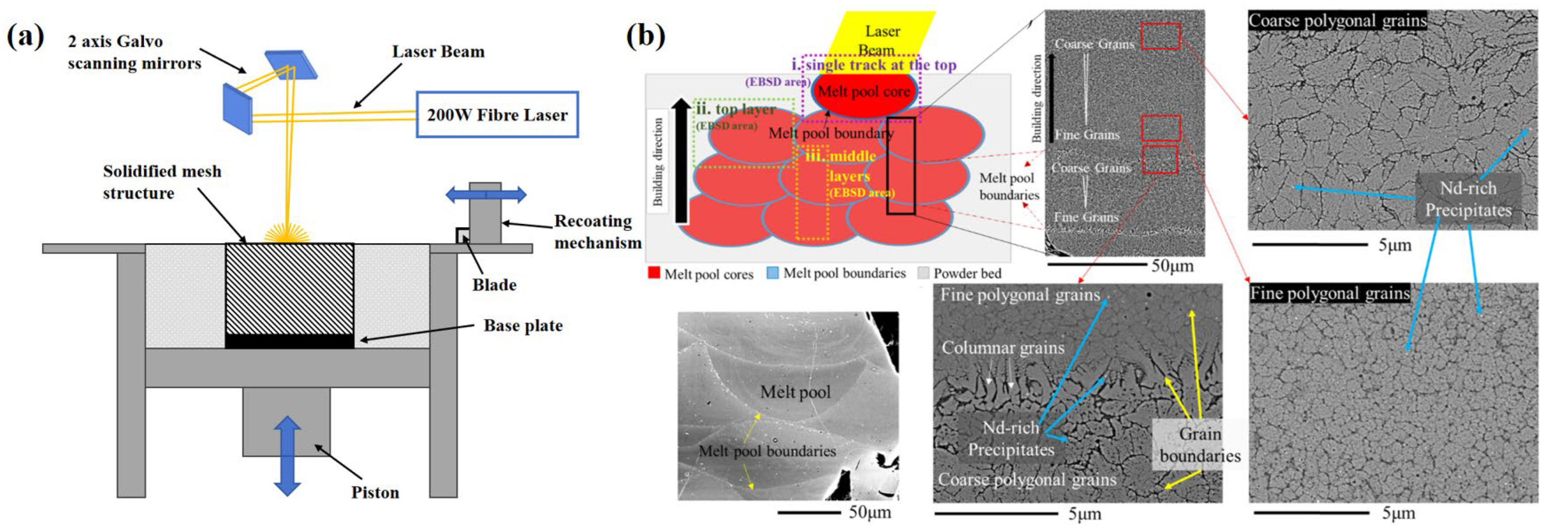
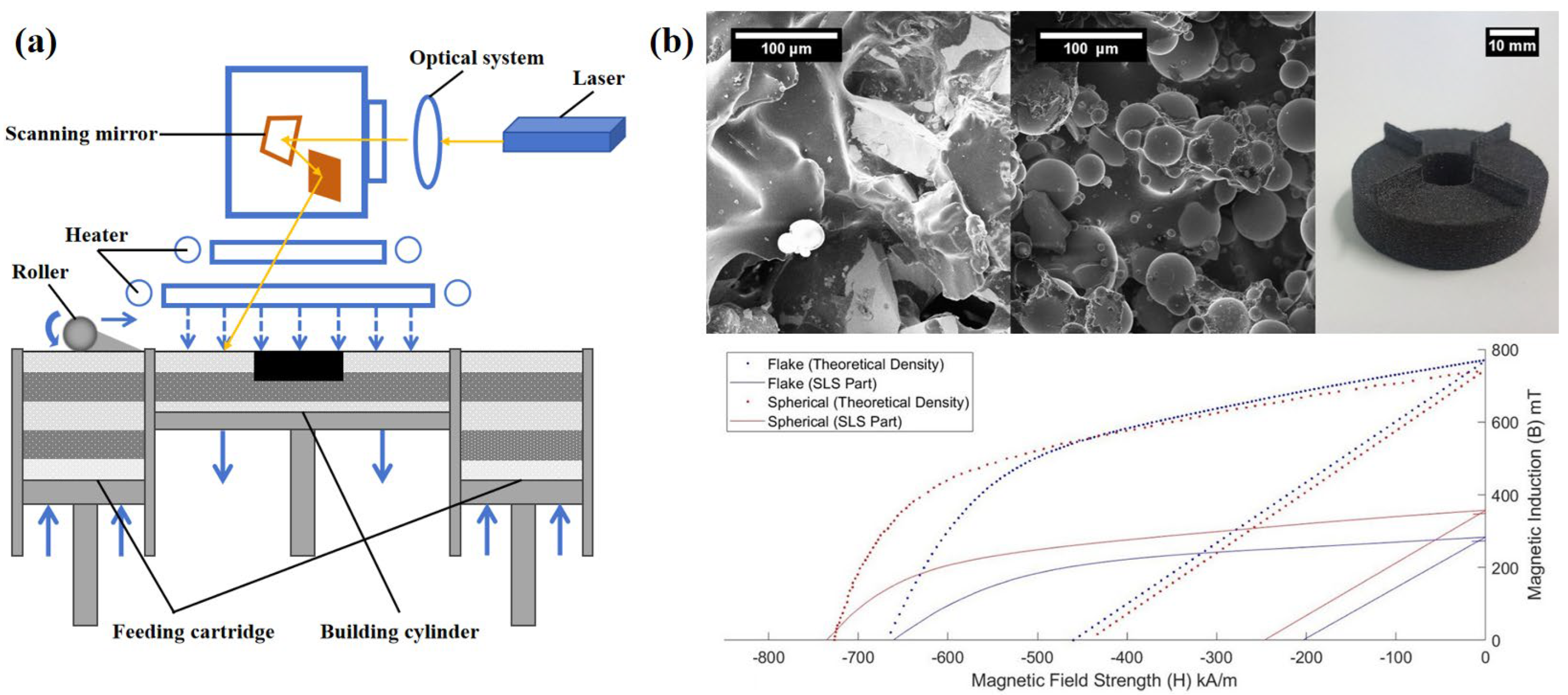
2.1. Laser Powder Bed Fusion (LPBF) Nd-Fe-B Magnets

The LPBF technology is mainly divided into selective laser melting (SLM) and selective laser sintering (SLS). SLM technology is a technique that utilizes metal powders that are completely melted under the heat of a laser beam and solidified by cooling [53]. The SLM technology produces three-dimensional solids by accumulating layers and does not require a binder. In the SLM process, the peritectic reaction of the melt pool at a high cooling rate is the key to the formation of the Nd2Fe14B intermetallic phase and small grain size, which contributes to the improvement in Hc. The printing parameters of SLM technology mainly consist of laser power (LP), laser focusing (LF), point distance of laser movement (PD), time of laser radiation of powder (ET), thickness of deposited fresh powder layer (LT), and horizontal movement of the laser—hatching distance (HD). The schematic diagram of SLM technology is shown in Figure 2a [54]. Because the magnetic properties are sensitive to the intergranular phase of Nd2Fe14B and the grain size, the process of SLM Nd-Fe-B magnets is harder to control compared with that of SLM structure materials such as steels and titanium alloys. Recently, researchers have explored the printing parameters for phase formation and grain size control of SLM magnets, as well as the microstructural changes during the SLM process. J. Jaćimović et al. [40] accomplished the parameter tuning through systematic variations of six independent printing parameters. A very concentrated micron-sized melting volume was ensured by a unique combination of parameters, which could be cooled quickly (104–106 K/s). The grain size of the printed Nd2Fe14B phase was only 1 μm, which was an order of magnitude smaller than that of sintered magnets. This resulted in very good magnetic properties of the additively manufactured samples without additional post-heat treatment. The AM samples reached remanence (Br) of 0.59 T, Hc of 695 kA/m, and (BH)max of 45 kJ/m3. And they proposed a complex AM magnet with a cooling channel, as shown in Figure 1f, which can provide a new strategy to decrease the temperature of motors. Bittner F et al. [49] used the SLM technology to prepare a Nd-Fe-B magnet with Hc of 921 kA/m, Br of 0.63 T, and (BH)max of 63 kJ/m3 without further additions of Nd-rich, low-melting-point alloys or other post-treatments. Julan Wu et al. [55] presented an in-depth analysis of the AM magnet’s grain structure for the first time in terms of morphology, size distribution, and texture. They investigated the formation and transformation mechanisms of complex phases and the development of nanocrystalline microstructures during the SLM process and found that remelting during processing leads to the transformation of coarse grains in the solidified layer into fine grains, which is shown in Figure 2b, and it is favorable for the improvement of magnet properties. The Br, Hc, and (BH)max of the Nd-Fe-B magnet are 0.65 T, 603 kA/m, and 62 kJ/m3, respectively. Tosoni, O et al. [52] presented a method for screening Nd–Fe–B alloy compositions for LPBF using monorail scanning and suction casting. AM Nd-Fe-B magnets with high Hc were prepared by SLM. The Br of the magnet after the annealing process was 0.62 T, Hc was 1790 kA/m, and (BH)max was 65 kJ/m3. This is the highest Hc reported thus far for AM Nd-Fe-B magnets. Although a lot of work to improve the AM process parameters has been undertaken, it is hard to make the magnetic properties like (BH)max close to the sintered ones due to its non-uniform grain sizes during the SLM process, which leads to the deterioration in properties.
SLS technology represents another facet of LPBF methodologies, facilitating the creation of additively manufactured components through the selective partial melting of consecutive material layers via laser beam interaction within a powder bed. The schematic diagram of SLS technology is shown in Figure 3a. The raw materials for the preparation of magnets by the SLS process are mainly mixtures of Nd-Fe-B magnetic powder with low-melting-point alloys or polyamides. In the SLS process, magnets are shaped by partially melting a low-melting-point alloy or polyamide as a binder. P. P. Wendhausen et al. [56] prepared bonded Nd-Fe-B magnets with SLS technology. A mixture of spherical isotropic powder of NdFeB-based alloy and polyamide-12 (6 wt.%) was used as the process feedstock. The mechanical resistance and magnetic properties were optimized by varying the amount of binder. It was found that magnetic properties can be improved by reducing hatching space and layer thickness, with an average value of 0.33 T for Br, 696 kA/m for Hc, and 17.1 kJ/m3 for (BH)max. Martin Mapley et al. [57] compared the geometries, densities, and magnetic properties of magnets produced by mixing isotropic Nd-Fe-B powders in both spherical and flake forms with polyamide-12 powder (40 vol.%) binders. The Hc of SLS magnets prepared from spherical and flake magnetic powders were 735 kA/m and 661 kA/m, the Br were 0.36 T and 0.30 T, the morphology and demagnetization curves of flake and spherical magnets prepared by SLS technology were shown in Figure 3b. Schäfer K et al. [51] prepared AM magnets with binder (PA12) content ranging from 2.5 to 30 wt.% by SLS technology. It was found that the Br decreased with the increase of additive content (0.338 T to 0.172 T). But the Hc increased from 670 kA/m to 750 kA/m. This observed improvement of the coercivity for high additive content can be explained by the decreased ability of the magnetic particles to rotate during the demagnetization process. Huber C et al. [58] increased the Hc of magnets from 520 kA/m to 1200 kA/m by using low melting point Nd-Cu, Nd-Al-Ni-Cu, and Nd-Tb-Cu alloys added to SLS Nd-Fe-B magnets during grain boundary infiltration. The presence of the magnet’s Nd-rich grain boundary phases and a Tb-rich shell layer encapsulating the surface of the Nd2Fe14B grains, as well as the preservation of grain size at the nanoscale grain size magnets, are responsible for the Hc enhancement. A.S. Volegov et al. [59] demonstrated the feasibility of single-step additive manufacturing of heavy rare earth-free high-coercivity Nd-Fe-B magnets with Hc up to 1280 kA/m. This is due to the integration of in situ grain boundaries (GBs) infiltration of low-melting-point paramagnetic alloys (20 wt.%) into the SLS process. Maltseva V.E. et al. [60] incorporated 20 wt.% Pr-Cu-Co alloy into Nd-Fe-B magnetic powders to achieve grain boundary infiltration through the SLS process. The high Hc PrCo5 phase was formed in the process, which effectively enhanced the Hc of AM magnets, reaching 1552.2 kA/m. Schäfer, K et al. [61] proposed the use of in situ mechanical arrangement of anisotropic particles in a single step to achieve magnetic field orientation of magnets without the need for an applied magnetic field source. A mixture of anisotropic Nd-Fe-B powder and PA12 was used to prepare anisotropic bonded magnets by the SLS process. The Br of the magnet is 0.38 T, and the (BH)max is 28.6 kJ/m3. In SLS magnets, the presence of non-magnetic substances, such as polyamides, results in a degradation of magnetic properties. However, when low-melting-point alloys are added for grain boundary infiltration, demagnetization can be effectively prevented, thereby enhancing Hc.

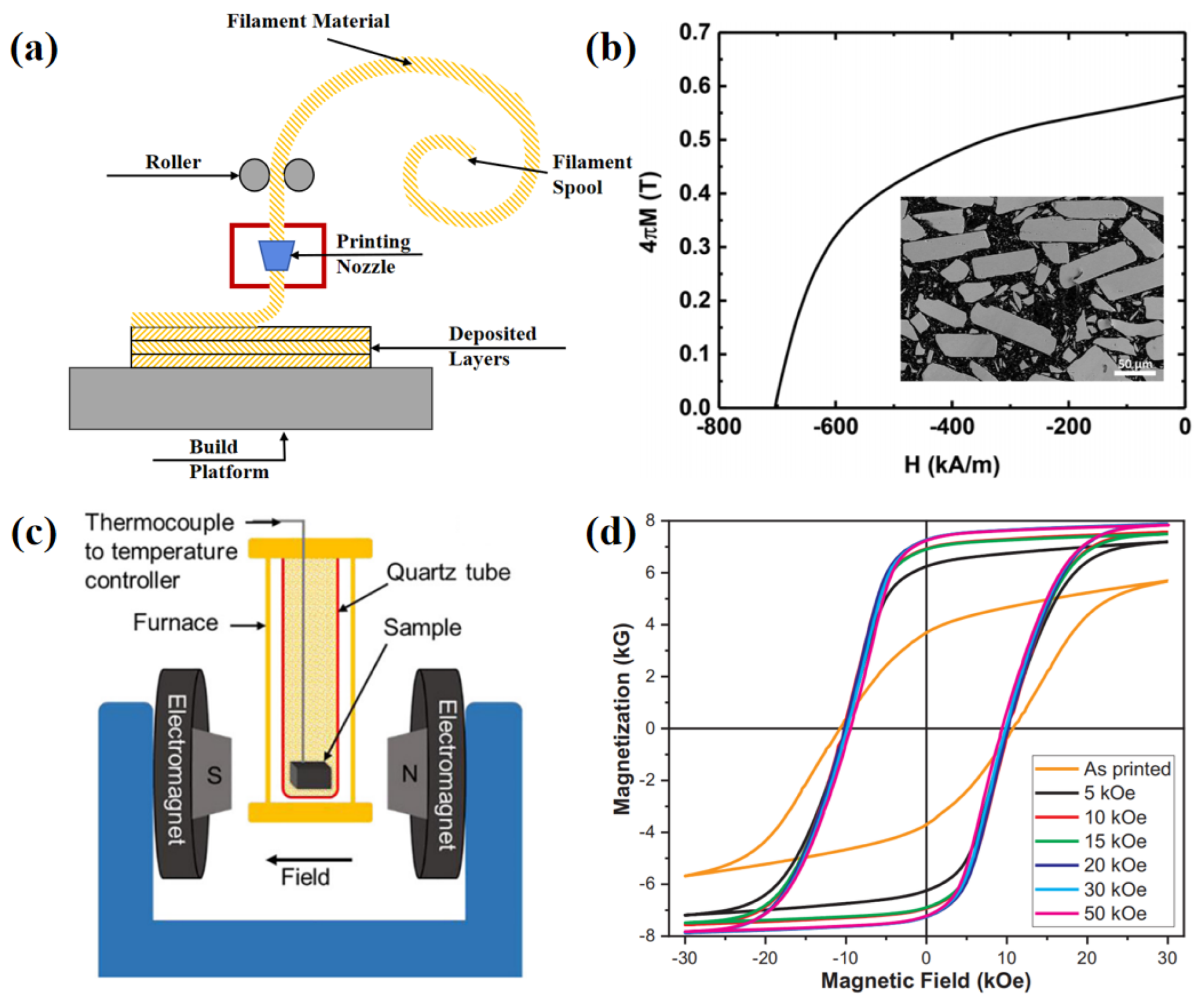
2.2. Fused Deposition Modeling (FDM) Nd-Fe-B Magnets

The principle of FDM is that the prepared precursor (filament) melts into a liquid through the heater extrusion head. Then, the melted material filament is extruded through the nozzle. From the extrusion head, it then moves along the contour of each cross-section of the part. Then, the semi-fluid thermoplastic material deposition curing covered in the constructed parts above is extruded, and within 0.1 s of rapid solidification, each layer of molding in the table will drop the layer height, the nozzle, and then the next layer of the cross-section scanning spray wire. And repeatedly, layer-by-layer deposition will occur until it reaches the last layer so that the accumulation of a solid model or part is formed from the bottom to the top in each layer. The schematic diagram of FDM technology is shown in Figure 4a. In FDM technology, the presence of binders such as PA reduces the content of Nd-Fe-B magnetic powder, thus leading to a decrease in magnetic properties. How to reduce the content of the binder while ensuring the magnet shaping is a key issue in the preparation of Nd-Fe-B magnets by FDM technology. Huber C et al. [47] prepared Nd-Fe-B, and PA mixed magnets using FDM technology and compared them with traditional injection molding process magnets. The Hc and Br of the FDM magnet were 740 kA/m and 0.31 T. This is due to the lower density of the FDM sample (3.57 g/cm3) than that of the injection molded sample (4.35 g/cm3). Li L et al. [40] prepared high-density isotropic Nd-Fe-B PA-bonded magnets by using FDM technology. The original Nd-Fe-B magnetic powder content of the magnet reached 70 vol.%, and the density of the magnet was 5.2 g/cm3. The Br of the Nd-Fe-B magnet was 0.58 T, the Hc was 708.2 kA/m, and the (BH)max was 58.1 kJ/m3. The demagnetization curve and morphology of the magnet are shown in Figure 4b. Gandha K et al. [29] added an applied magnetic field to the FDM process to achieve magnetic alignment during the printing process; the schematic experimental set-up for post-alignment of printed bonded magnets in an electromagnet is shown in Figure 4c. The results showed that the (BH)max of the FDM magnet (65 vol.% Nd-Fe-B + Sm-Fe-N) under a 2 T magnetic field reached 89.9 kJ/m3, and the Hc and Br of the magnet are 811.7 kA/m and 0.73 T; the hysteresis loops of magnets under different magnetic fields are shown in Figure 4d. In addition to improving the AM magnet performance by increasing the magnetic powder content, it is also possible to integrate a magnetic field source into FDM equipment, which can achieve in situ magnetic alignment of anisotropic magnetic powders during the printing process while retaining the other advantages of FDM technology.

2.3. Binder Jetting (BJ) Nd-Fe-B Magnets

The BJ process refers to the way that each layer of magnetic powders is coated with a layer of liquid thermosetting binder, and then the print body is cured in an oven [62]. The BJ process consists of a powder bed for the build area, a roller, an inkjet print head, and a powder hopper or feed bin to supply the powder, as Figure 5a shows. The process begins by reducing the build volume to the desired layer thickness and then using the roller to spread a thin layer of powder over the build area. The print head then passes over the build area and selectively deposits the adhesive into the two-dimensional cross-sectional shape of the current pattern [63,64]. Paranthaman et al. [65] successfully prepared near-net-shape binder jet-bonded magnets; since the surface of the magnets prepared by the BJ process was rough and porous, the magnets were dip-coated in a clear polyurethane to increase the mechanical strength and improve the surface quality. Binder jet magnets with a measured density of nearly 46% were achieved. The Br of the binder jet magnet samples was about 0.3 T, which is not yet up to the Br of conventional injection molding and compression-bonded isotropic Nd-Fe-B magnets of 0.5 T and 0.65 T, respectively. Based on the BJ process, Li et al. [63] used a low-melting-point alloy (Nd-Cu-Co, Pr-Cu-Co) infiltration process to improve the performance of Nd-Fe-B magnets and successfully increased the Hc of magnets from 732 kA/m to 1345 kA/m. The elemental infiltrating distribution and demagnetization curves are shown in Figure 5b. The densities of magnets permeated by low-melting-point alloys are increased, with densities raised from 3.3 g/cm3 to 4.3 g/cm3. The BJ technology incorporating the alloy infiltration process delays the formation of antimagnetic domains by enhancing the anisotropic field on the grain surface, thus increasing the Hc of the whole magnet. However, the addition of paramagnetic material in Nd-Fe-B material leads to a decrease in the magnetization of the magnet.
The distribution of Br and Hc of Nd-Fe-B permanent magnet materials prepared by four typical AM techniques and two traditional techniques is shown in Figure 6. Among them, the blue area is the Nd-Fe-B magnet prepared by SLM technology. The overall Br is higher (from 0.59 T to 0.9 T), and the Hc distribution is from 659 kA/m to 1025 kA/m, which may be related to the solidification rate during the printing process. The pink area is the Nd-Fe-B magnet prepared by SLS technology; the Br is low (from 0.33 T to 0.44 T), and the Hc distribution is from 520 kA/m to 1200 kA/m. The high Hc is due to the addition of grain boundary infiltration in the SLS process, which inhibits the formation of reversed magnetic domains. The green area is the Nd-Fe-B magnet prepared by FDM technology, with average Hc and large Br difference (from 0.31 T to 0.73 T). In the FDM process, when the non-magnetic phase, such as binder content, is high, the magnet density decreases, and the magnet Br is weakened. The orange region is the Nd-Fe-B magnet prepared by BJ technology, and the Br is the lowest level among the several methods, possibly because of the presence of the binder. The purple and yellow region is the Nd-Fe-B magnet prepared by traditional sintering and traditional bonded techniques. AM technology has even exceeded the performance level of traditional bonded magnets, but there is still a big gap between the performance of traditional sintered magnets. Researchers have explored the improvement of Hc of magnets prepared by AM technology, but the problem of low Br is the key to restricting the improvement of the overall performance of magnets. For bonded AM magnets, the Br can be improved by increasing the density of the magnet while ensuring its shape. But for full-density AM magnets, improving Hc is the key to further development.

3. Additive Manufacturing of Sm-Co Rare Earth Permanent Magnet Materials

SmCo5 and Sm2Co17 are first- and second-generation rare earth permanent magnetic materials with high Tc and thermal stability and are often used in high-temperature environments. One of the disadvantages of these magnets is that they are oxidized very easily and contain high amounts of cobalt and samarium, resulting in high costs [68]. Since the Sm-Co magnets are mostly used in high-temperature environments, it is not common to manufacture bonded Sm-Co magnets with low operating temperatures due to the presence of binders. Generally, the recovered Sm-Co magnetic powder is used to prepare bonded Sm-Co magnets, which can save costs and recover rare earth elements. Full-density Sm-Co magnets are usually manufactured using LPBF technology.

3.1. Additive Manufacturing of SmCo5 Rare Earth Permanent Magnet Materials

On the AM technology side of Bonded SmCo5 magnets, Khazdozian H A et al. [69] investigated the preparation of magnetic wires by extrusion molding of recycled Sm-Co powder in PLA binder. Improvement in magnetic properties was observed when recycled Sm-Co powder was added to PLA as compared to pristine powder, probably due to minimization of particle rotation. The Hc of the obtained magnetic wires was 714 kA/m, and Br was 0.088 T (0.88 kG), which is shown in Figure 7a. Huang J et al. [70] successfully prepared SmCo5 cylindrical specimens using laser sintering technology and investigated the effect of the laser sintering process on the phase structure and magnetic properties of the magnets. It was found that the higher laser power makes the energy distribution in the sample uniform while enhancing the crystallization and magnetic properties of the sample. The effect of scanning speed on crystal structure and magnetic properties is opposite to that of laser power. The increase in the number of sintering times also seriously affects the crystal structure and has a negative impact. A slight increase in laser power caused an increase in coercivity owing to the increase in inter-particle dipole interaction, resulting in improved crystallization in the (101) and (110) phases. A faster laser speed causes a negative effect on the crystal structure, owing to the low laser duration causing rapid cooling, which in turn results in poorer crystallization. Increasing the laser-sintering time significantly weakened the crystallization of the materials, resulting in a decrease in the saturation magnetization. So, the optimum process parameters for laser sintering of SmCo5 materials were established as 0.254 mm laser scanning distance, 150 W laser power, 1270 mm/min scanning speed, and one sintering. The Hc of the obtained magnets was 126 kA/m. Due to the fluctuation of the particle size distribution of the magnetic powders, some magnetic powders are agglomerated, which has an impact on the performance of the Sm-Co magnets prepared by AM technology.

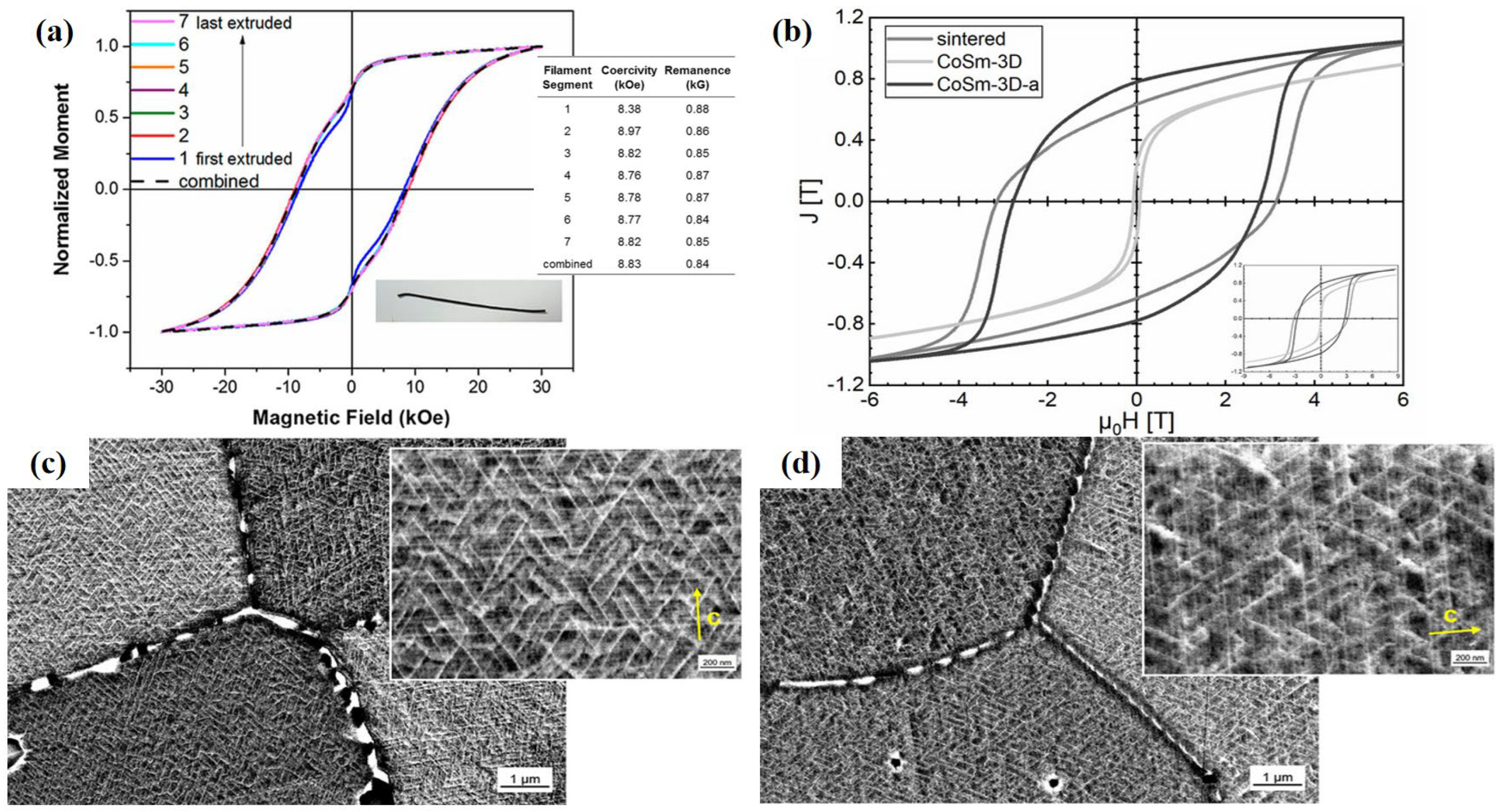
3.2. Additive Manufacturing of Sm2Co17 Rare Earth Permanent Magnet Materials

The annealing process can improve the squareness and Br of AM Sm-Co magnets and refine the grain structure of the magnets. Goll D et al. [71] prepared (CoCuFeZr)17Sm2 magnets using LPBF technology. The prepared magnets were treated by a three-step annealing process (homogenization, isothermal thermal treatment, and slow cooling), and the obtained magnets had a Hc of 2204 kA/m, Br of 0.78 T, and (BH)max of 109.4 kJ/m3. The comparison of the hysteresis line of AM magnets treated by the annealing process with that of the printed state and the conventional isotropic sintered magnets is shown in Figure 7b. As expected, in the as-built state, the printed part exhibited low Hc. A three-step annealing process was necessary to increase Hc. Under the annealed condition, the samples exhibited good magnetic properties. It can be found that the Br of the annealed magnet was slightly higher than that of the conventional isotropic sintered magnet, but the Hc was relatively weaker. The microstructure of SLM (CoCuFeZr)17Sm2 in the annealed state and a reference isotropic sintered magnet are shown in Figure 7c,d. And the domain structure of the annealed magnet was obviously refined and very similar to that of the sintered magnet. This reflects that the whole AM magnet formed a relatively uniform nanostructure.

4. Additive Manufacturing of Sm-Fe Rare Earth Permanent Magnet Materials

The theoretical (BH)max of Sm-Fe magnets reaches a level approximating that of Nd-Fe-B magnets. And its Hc and Tc are much higher than that of Nd-Fe-B, which can be more widely used in high-temperature environments such as electric motors. Meanwhile, Sm-Fe magnets do not require the addition of heavy rare earth elements and strategic metal elements, making them a strong candidate for the new generation of rare earth permanent magnet materials.

4.1. Additive Manufacturing of Sm(Fe, T)12 Rare Earth Permanent Magnet Materials

Sm(Fe, T)12 compounds (where T = Ti, V, Cr, Mo, Si, Zr, etc.) discovered by Ohashi et al. [43] were considered promising compounds for new types of permanent magnets. These compounds have higher intrinsic magnetic properties (Hc and Ms) than Nd-Fe-B in the temperature range of 100–400 °C. Moreover, the essential advantage of Sm(Fe, T)12 compounds is that they have the lowest rare earth metal content compared to other rare earth compounds considered for permanent magnet fabrication. The magnetic properties of Sm(Fe, T)12 can be effectively enhanced by elemental substitution. A proof of concept for additive manufacturing of (Sm, Zr)Fe11Ti permanent magnets was presented by Neznakhin et al. [72]. The permanent magnets were prepared by a selective laser melting method using (Sm, Zr)Fe11Ti powder and its mixtures with a low-melting-point additive Sm75(Cu, Co)25. The additive facilitates liquid-phase sintering of the main alloy particles without causing drastic changes in the microstructure of the alloy. During the SLM, the additive was fully melted, the main fraction remained solid, and the low-melting additive reacted with the surface of the main powder particles. The photograph of the SLM-prepared sample on the substrate and a schematic of the laser beam scanning strategy and the magnetic hysteresis loops measured at 300 K are shown in Figure 8a,b. The laser beam moved from the left to the right side of the sample in one direction. Then, when the laser was turned off, the focus moved to a new scan line. The low-melting-point additives ensured that the phase composition and core structure of the powder particles remained unchanged. The Hc reached 256 kA/m in the sample with Sm5Fe17 main phase and 240 kA/m in the case of (Sm,Zr)Fe11Ti.

4.2. Additive Manufacturing of Sm-Fe-N Rare Earth Permanent Magnet Materials

Sm-Fe-N-based materials emerge as an option for isotropic and anisotropic magnets due to their high Br, Hc, and corrosion resistance [38,74,75]. J.A.B. Engerroff et al. [67] prepared isotropic Sm-Fe-N bonded magnets using LPBF technology from Sm-Fe-N and polyamide-12 particles. Higher interparticle porosity was found in the samples during LPBF melting but did not affect the main phase of the samples. Thus, interparticle porosity was likely to be regions that underwent lower local energy density during processing. The higher interparticle porosity led to the degradation of the magnetic properties of the samples, and it was proposed that the combination of cold isostatic pressing (CIP) technique after the LPBF process effectively improves the magnetic properties of the samples. Through the CIP process, the magnetic properties of AM magnets had been effectively improved, and the Br was mainly increased greatly, from 0.24 T to 0.4 T. Suppan et al. [73] reported the first in situ weaving development method for fused filament fabrication (FFF) of strontium hexaferrite (SrFe12O19) and Sm2Fe17N3 anisotropic bonded magnets. In their work, filaments of the two magnetic fillers were extruded on the surface of a Sm2Co17 permanent magnet that provided an external magnetic field (Figure 8d), which allowed the adjustment of the particle magnetic field orientation during the additive manufacturing process. For Sm2Fe17N3 + PA12, the normalized magnetization (Mr/Ms) along the easy axis was 0.65 and 0.55 in the direction of the hard axis, the Hc was 957.6 kA/m, which is shown in Figure 8c. This is an efficient method to obtain anisotropic AM-bonded magnets. The grain refinement is one way to enhance magnetic properties, but a magnetic powder that is too fine is unsuitable for AM. To avoid this apparent contradiction, Röhrig, M et al. [76] refined the microstructure of the grains by Hydrogenation–Disproportionation–Desorption–Recombination (HDDR) to increase the Hc rather than reducing the powder size. The obtained Sm-Fe-N magnetic powders had Hc values in the range of 683–777 kA/m. AM magnets prepared using this powder have densities of up to 4.2 g/cm3.
The magnetic properties of some rare earth permanent magnets prepared by different AM methods are shown in Table 1. The current research progress is mainly based on the additive manufacturing technology of Nd-Fe-B magnets, among which bonded Nd-Fe-B magnets have poor performance due to the existence of binders of non-magnetic materials. Researchers have explored ways to improve the performance of AM process magnets. For example, through the penetration process of low-melting-point alloy, the low-melting-point alloy is dispersed around the magnetic phase grain boundary, and the Hc of the magnet is significantly increased. At the same time, the introduction of a magnetic field source in the AM process is also an effective way to prepare anisotropic magnets. Similarly, the magnetic properties of AM magnets can also be effectively improved through post-treatment processes, such as CIP and annealing. At the same time, owing to the unique high design freedom of AM technology, researchers have also attempted to take advantage of AM technology by designing custom shapes, such as microscopic cooling channels. However, because there is no suitable method to regulate the magnetic field of a special-shaped magnet, its magnetic properties need to be improved.

5. Summary and Overlook

Overall, the research on AM technology of rare earth permanent magnet materials is still in its early stages. The AM technology for rare earth permanent magnetic materials mainly includes selective laser melting and selective laser sintering based on laser powder bed melting, laser-free fused deposition modeling, and binder jetting. In the literature on AM Nd-Fe-B magnets, most of the research results reported so far are isotropic bonded magnets whose performance has reached the standard of traditional bonded Nd-Fe-B magnets. However, the magnetic properties of fully dense AM Nd-Fe-B magnets prepared based on laser powder bed melting are not yet satisfactory. Due to the high cost, less research has been conducted on the AM technology of Sm-Co magnets. Sm-Fe magnets without the strategic element Co have gradually been emphasized by researchers due to their potentially high magnetic properties, and its AM technology is of great significance to future research on the forming process of Sm-Fe magnets. At present, the largest challenge of AM magnets is to improve their magnetic properties, and the following aspects need to be focused on:
(1) Optimize AM process parameters. By investigating the mechanism of the influence of powder melting, solidification, or bonding process on magnetic properties, a correlation between the AM process parameters and the microstructure of magnets in different AM types, including LPBF, FDM, and BJ, should be established. Therefore, data-driven optimizing methods like machine learning could be used to improve the magnetic properties, and external processing methods like in situ magnetic field alignment, in situ grain boundary infiltration, and post-processing could focus on enhancing the magnetic properties of AM magnets.
(2) Introduce external processing methods. In addition to regulating the process parameters of the AM process, external processing methods like in situ magnetic field alignment, in situ grain boundary infiltration, and post-processing could focus on enhancing the magnetic properties of AM magnets.
(3) Utilize the designability of AM technology. Due to its high design freedom for rare earth permanent magnets in terms of size, shape, and magnetic field distribution in AM technology, we can reasonably allocate the deposition location of expensive raw materials like heavy rare earth elements, which can reduce the loss of raw materials and energy loss during the preparation process and achieve cost savings. Therefore, the same focus should be placed on the research and development of special structures and special stray field magnets in the future.

Author Contributions

Conceptualization, Y.C. and C.X.; writing—original draft preparation, Y.C.; writing—review and editing, C.X. and Y.L.; funding acquisition, C.X. and Y.L. All authors have read and agreed to the published version of the manuscript.

Funding

This research was funded by the HQD Project of the Ministry of Industry and Information Technology, grant numbers “2023ZY01012” and “2023ZY01010”. The APC was funded by the Technology Development Fund of China Academy of Machinery Science and Technology Group, grant number “912202Q9”.

Data Availability Statement

Not applicable.

Conflicts of Interest

All authors were employed by the company Beijing National Innovation Institute of Lightweight Ltd. All authors declare that the research was conducted in the absence of any commercial or financial relationships that could be construed as a potential conflict of interest.

References

  1. Nakamura, H. The current and future status of rare earth permanent magnets. Scr. Mater. 2018, 154, 273–276. [Google Scholar] [CrossRef]
  2. Poudel, B.; Amiri, E.; Rastgoufard, P.; Mirafzal, B. Toward Less Rare-Earth Permanent Magnet in Electric Machines: A Review. IEEE Trans. Magn. 2021, 57, 900119. [Google Scholar] [CrossRef]
  3. Zheng, S.; Zhu, X.; Xiang, Z.; Xu, L.; Zhang, L.; Lee, C. Technology trends, challenges, and opportunities of reduced-rare-earth PM motor for modern electric vehicles. Green Energy Intell. Transport. 2022, 1, 100012. [Google Scholar] [CrossRef]
  4. Tao, S.; Ahmad, Z.; Zhang, P.; Zheng, X.; Zhang, S. Magnetic and structural properties of nanocomposite permanent magnet produced from crystallization of Pr4Fe67Nb4Cu2Zr1B22 alloy. J. Magn. Magn. Mater. 2023, 568, 170368. [Google Scholar] [CrossRef]
  5. Wu, Y.; Skokov, K.P.; Schäfer, L.; Maccari, F.; Aubert, A.; Xu, H.; Wu, H.; Jiang, C.; Gutfleisch, O. Microstructure, coercivity and thermal stability of nanostructured (Nd,Ce)-(Fe,Co)-B hot-compacted permanent magnets. Acta Mater. 2022, 235, 118062. [Google Scholar] [CrossRef]
  6. Trench, A.; Sykes, J.P. Rare Earth Permanent Magnets and Their Place in the Future Economy. Engineering 2020, 6, 115–118. [Google Scholar] [CrossRef]
  7. Lucarini, S.; Hossain, M.; Garcia-Gonzalez, D. Recent advances in hard-magnetic soft composites: Synthesis, characterisation, computational modelling, and applications. Compos. Struct. 2022, 279, 114800. [Google Scholar] [CrossRef]
  8. Alves, M.N.; Miró, M.; Breadmore, M.C.; Macka, M. Trends in analytical separations of magnetic (nano)particles. Trends Anal. Chem. 2019, 114, 89–97. [Google Scholar] [CrossRef]
  9. Coey, J.M.D. Perspective and Prospects for Rare Earth Permanent Magnets. Engineering 2020, 6, 119–131. [Google Scholar] [CrossRef]
  10. Skomski, R.; Coey, J.M.D. Giant Energy Product in Anostructured Two-Phase Magnets. Phys. Rev. B. 1993, 48, 15812–15816. [Google Scholar] [CrossRef] [PubMed]
  11. Wang, H.; Lamichhane, T.N.; Paranthaman, M.P. Review of additive manufacturing of permanent magnets for electrical machines: A prospective on wind turbine. Mater. Today Phys. 2022, 24, 100675. [Google Scholar] [CrossRef]
  12. Park, K.; Hirayama, Y.; Wang, J.; Kobashi, M. Ultra-high coercivity Sm-Co bulk magnets with remarkable thermal stability. Scr. Mater. 2022, 218, 114847. [Google Scholar] [CrossRef]
  13. Wang, L.; Wang, C.; Li, Q.; Liu, Y.; Fang, Y.; Yi, X.; Li, W. Correlation of mechanical anisotropy with fine grain strengthening for Sm2Co17-type sintered permanent magnets. J. Rare Earths 2022, 40, 1584–1591. [Google Scholar] [CrossRef]
  14. Strnat, K.; Hoffer, G.; Olson, J. A Family of New Cobalt-base Permanent Magnet Material. J. Appl. Phys. 1967, 38, 1001. [Google Scholar] [CrossRef]
  15. Velge, W.A.J.; Buschow, K.H. Magnetic and crystallographic properties of some rare earth cobalt compounds with CaZn5 structure. J. Appl. Phys. 1968, 39, 1717–1720. [Google Scholar] [CrossRef]
  16. Larson, P.; Mazin, I.I.; Papaconstantopoulos, D.A. Calculation of Magnetic Anisotropy Energy in SmCo5. Phys. Rev. B. 2003, 67, 214405. [Google Scholar] [CrossRef]
  17. Guo, K.; Lu, H.; Xu, G.J.; Liu, D.; Wang, H.B.; Liu, X.M.; Song, X.Y. Recent progress in nanocrystalline Sm–Co based magnets. Mater. Today Chem. 2022, 25, 100983. [Google Scholar] [CrossRef]
  18. Ojima, T.; Tomizawa, S.; Yoneyama, T.; Hori, T. New Type Rare Earth Cobalt Magnets with an Energy Product of 30 MGOe. Jpn. J. Appl. Phys. 1977, 16, 671–672. [Google Scholar] [CrossRef]
  19. Song, X.; Liu, Y.; Xiao, A.; Yuan, T.; Ma, T. Cell-boundary-structure controlled magnetic-domain-wall-pinning in 2:17-type Sm-Co-Fe-Cu-Zr permanent magnets. Mater. Charact. 2020, 169, 110575. [Google Scholar] [CrossRef]
  20. Sagawa, M.; Fujimura, S.; Togawa, N.; Yamamoto, H.; Matsuura, Y. New material for permanent magnets on a base of Nd and Fe (invited). J. Appl. Phys. 1984, 55, 2083–2087. [Google Scholar] [CrossRef]
  21. Matsuzaki. The maximum magnetic energy product of sintered NdFeB in Japan reaches a new high. Rare Earth Inf. 2005, 9, 12. [Google Scholar]
  22. Quan, W.; Ma, L.; Fan, J.; Chen, Y.; Zheng, Q.; Bian, B.; Zhang, J.; Du, J. Tripling magnetic energy product in magnetic hard/soft nanocomposite permanent magnets. Mater. Today Phys. 2022, 26, 100750. [Google Scholar] [CrossRef]
  23. Nong, H.T.T.; Mai, T.K.; Mercone, S. Tunable magnetic anisotropy in nanostructured permanent magnet: A micromagnetic study. J. Magn. Magn. Mater. 2019, 477, 109–117. [Google Scholar] [CrossRef]
  24. Yang, J.; Han, J.; Tian, H.; Zha, L.; Zhang, X.; Song Kim, C.; Liang, D.; Yang, W.; Liu, S.; Wang, C. Structural and Magnetic Properties of Nanocomposite Nd–Fe–B Prepared by Rapid Thermal Processing. Engineering 2020, 6, 132–140. [Google Scholar] [CrossRef]
  25. Crozier-Bioud, T.; Momeni, V.; Gonzalez-Gutierrez, J.; Kukla, C.; Luca, S.; Rolere, S. Current challenges in NdFeB permanent magnets manufacturing by Powder Injection Molding (PIM): A review. Mater. Today Phys. 2023, 34, 101082. [Google Scholar] [CrossRef]
  26. Delette, G. Nd2Fe14B permanent magnets substituted with non-critical light rare earth elements (Ce, La): A review. J. Magn. Magn. Mater. 2023, 577, 170768. [Google Scholar] [CrossRef]
  27. Li, L.; Post, B.; Kunc, V.; Elliott, A.M.; Paranthaman, M.P. Additive manufacturing of near-net-shape bonded magnets: Prospects and challenges. Scr. Mater. 2017, 135, 100–104. [Google Scholar] [CrossRef]
  28. Vladimir, P.; Andrey, K.; Iliya, R.; Fernando, M.; Gary, M. Prospects of additive manufacturing of rare-earth and non-rare-earth permanent magnets. Procedia Manuf. 2018, 21, 100–108. [Google Scholar]
  29. Gandha, K.; Li, L.; Nlebedim, I.C.; Post, B.K.; Kunc, V.; Sales, B.C.; Bell, J.; Paranthaman, M.P. Additive manufacturing of anisotropic hybrid NdFeB-SmFeN nylon composite bonded magnets. J. Magn. Magn. Mater. 2018, 467, 8–13. [Google Scholar] [CrossRef]
  30. Fim, R.G.T.; Mascheroni, A.A.; Antunes, L.F.; Engerroff, J.B.E.; Ahrens, C.H.; Wendhausen, P.A.P. Increasing packing density of Additively Manufactured Nd-Fe-B bonded magnets. Addit. Manuf. 2020, 35, 101353. [Google Scholar] [CrossRef]
  31. Martin, J.J.; Fiore, B.E.; Erb, R.M. Designing bioinspired composite reinforcement architectures via 3D magnetic printing. Nat. Commun. 2015, 6, 8641. [Google Scholar] [CrossRef]
  32. Périgo, E.A.; Jacimovic, J.; García Ferré, F.; Scherf, L.M. Additive manufacturing of magnetic materials. Addit. Manuf. 2019, 30, 100870. [Google Scholar] [CrossRef]
  33. Chaudhary, V.; Mantri, S.A.; Ramanujan, R.V.; Banerjee, R. Additive manufacturing of magnetic materials. Prog. Mater. Sci. 2020, 114, 100688. [Google Scholar] [CrossRef]
  34. Wu, J.; Aboulkhair, N.T.; Degano, M.; Ashcroft, I.; Hague, R.J.M. Process-structure-property relationships in laser powder bed fusion of permanent magnetic Nd-Fe-B. Mater. Des. 2021, 209, 109992. [Google Scholar] [CrossRef]
  35. Al Rashid, A.; Ahmed, W.; Khalid, M.Y.; Koç, M. Vat photopolymerization of polymers and polymer composites: Processes and applications. Addit. Manuf. 2021, 47, 102279. [Google Scholar] [CrossRef]
  36. Zhang, C.; Li, X.; Jiang, L.; Tang, D.; Xu, H.; Zhao, P.; Fu, J.; Zhou, Q.; Chen, Y. 3D Printing of Functional Magnetic Materials: From Design to Applications. Adv. Funct. Mater. 2021, 31, 2102777. [Google Scholar] [CrossRef]
  37. Huber, C.; Abert, C.; Bruckner, F.; Pfaff, C.; Kriwet, J.; Groenefeld, M.; Teliban, I.; Vogler, C.; Suess, D. Topology optimized and 3D printed polymer-bonded permanent magnets for a predefined external field. J. Appl. Phys. 2017, 122, 053904. [Google Scholar] [CrossRef]
  38. Gandha, K.; Nlebedim, I.C.; Kunc, V.; Lara-Curzio, E.; Fredette, R.; Paranthaman, M.P. Additive manufacturing of highly dense anisotropic Nd–Fe–B bonded magnets. Scr. Mater. 2020, 183, 91–95. [Google Scholar] [CrossRef]
  39. Pigliaru, L.; Paleari, L.; Bragaglia, M.; Nanni, F.; Ghidini, T.; Rinaldi, M. Poly-ether-ether-ketone—Neodymium-iron-boron bonded permanent magnets via fused filament fabrication. Synth. Met. 2021, 279, 116857. [Google Scholar] [CrossRef]
  40. Li, L.; Jones, K.; Sales, B.; Pries, J.L.; Nlebedim, I.C.; Jin, K.; Bei, H.; Post, B.K.; Kesler, M.S.; Rios, O.; et al. Fabrication of highly dense isotropic Nd-Fe-B nylon bonded magnets via extrusion-based additive manufacturing. Addit. Manuf. 2018, 21, 495–500. [Google Scholar] [CrossRef]
  41. Kume, M.; Tomimoto, T.; Yamamoto, M.; Ihara, K.; Yoshiwara, H.; Tada, S.; Sumitomo, M. Progress and Prospects of SmFeN Magnets. J. Jpn. Inst. Met. 2012, 76, 107–111. [Google Scholar] [CrossRef]
  42. Chatzipirpiridis, G.; Gervasoni, S.; Fischer, C.; Ergeneman, O.; Pellicer, E.; Nelson, B.J.; Pané, S. 3D Printing of Thermoplastic-Bonded Soft- and Hard-Magnetic Composites: Magnetically Tuneable Architectures and Functional Devices. Adv. Intell. Syst. 2019, 1, 1900069. [Google Scholar] [CrossRef]
  43. Jaćimović, J.; Binda, F.; Herrmann, L.G.; Greuter, F.; Genta, J.; Calvo, M.; Tomse, T.; Simon, R.A. Net Shape 3D Printed NdFeB Permanent Magnet. Adv. Eng. Mater. 2017, 19, 1700098. [Google Scholar] [CrossRef]
  44. Hu, K.; Yu, T.; Tang, S.; Xu, X.; Guo, Z.; Qian, J.; Cheng, Y.; Zhao, Y.; Yan, S.; Zhang, H.; et al. Dual anisotropicity comprising 3D printed structures and magnetic nanoparticle assemblies: Towards the promotion of mesenchymal stem cell osteogenic differentiation. NPG Asia Mater. 2021, 13, 19. [Google Scholar] [CrossRef]
  45. Huber, C.; Goertler, M.; Abert, C.; Bruckner, F.; Groenefeld, M.; Teliban, I.; Suess, D. Additive Manufactured and Topology Optimized Passive Shimming Elements for Permanent Magnetic Systems. Sci. Rep. 2018, 8, 14651. [Google Scholar] [CrossRef]
  46. Ohashi, K.; Yokoyama, T.; Osugi, R.; Tawara, Y. The magnetic and structural properties of R-Ti-Fe ternary compounds. IEEE Trans. Magn. 1987, 23, 3101–3103. [Google Scholar] [CrossRef]
  47. Huber, C.; Abert, C.; Bruckner, F.; Groenefeld, M.; Muthsam, O.; Schuschnigg, S.; Sirak, K.; Thanhoffer, R.; Teliban, I.; Vogler, C.; et al. 3D print of polymer bonded rare-earth magnets, and 3D magnetic field scanning with an end-user 3D printer. Appl. Phys. Lett. 2016, 109, 162401. [Google Scholar] [CrossRef]
  48. Ehrmann, G.; Blachowicz, T.; Ehrmann, A. Magnetic 3D-Printed Composites—Production and Applications. Polymers 2022, 14, 3895. [Google Scholar] [CrossRef]
  49. Bittner, F.; Thielsch, J.; Drossel, W.G. Microstructure and magnetic properties of Nd-Fe-B permanent magnets produced by laser powder bed fusion. Scr. Mater. 2021, 201, 113921. [Google Scholar] [CrossRef]
  50. Yu, K.S.; Cheng, C.W.; Lee, A.C.; Jhang Jian, W.Y.; Chang, W.C.; Chang, T.W.; Tsai, M.C. Additive manufacturing of NdFeB magnets by synchronized three-beam laser powder bed fusion. Opt. Laser Technol. 2022, 146, 107604. [Google Scholar] [CrossRef]
  51. Schäfer, K.; Braun, T.; Riegg, S.; Musekamp, J.; Gutfleisch, O. Polymer-bonded magnets produced by laser powder bed fusion: Influence of powder morphology, filler fraction and energy input on the magnetic and mechanical properties. Mater. Res. Bull. 2023, 158, 112051. [Google Scholar] [CrossRef]
  52. Tosoni, O.; Borges Mendonça, E.; Reijonen, J.; Antikainen, A.; Schäfer, L.; Riegg, S.; Gutfleisch, O. High-coercivity copper-rich Nd-Fe-B magnets by powder bed fusion using laser beam method. Addit. Manuf. 2023, 64, 103426. [Google Scholar] [CrossRef]
  53. Jacimovic, J.; Christen, T.; Dénervaud, E. Self-organized giant magnetic structures via additive manufacturing in NdFeB permanent magnets. Addit. Manuf. 2020, 34, 101288. [Google Scholar] [CrossRef]
  54. Ferrar, B.; Mullen, L.; Jones, E.; Stamp, R.; Sutcliffe, C.J. Gas flow effects on selective laser melting (SLM) manufacturing performance. J. Mater. Process. Technol. 2012, 212, 355–364. [Google Scholar] [CrossRef]
  55. Wu, J.; Aboulkhair, N.T.; Robertson, S.; Zhou, Z.; Bagot, P.A.J.; Moody, M.P.; Degano, M.; Ashcroft, I.; Hague, R.J.M. Amorphous-crystalline nanostructured Nd-Fe-B permanent magnets using laser powder bed fusion: Metallurgy and mag-netic properties. Acta Mater. 2023, 259, 119239. [Google Scholar] [CrossRef]
  56. Wendhausen, P.P.; Ahrens, C.H.; Baldissera, A.B.; Pavez, P.D.; Mascheroni, J.M. Additive Manufacturing of Bonded NdFeB, Process Parameters Evaluation on Magnetic Properties. In Proceedings of the 2017 IEEE International Magnetics Conference (INTERMAG), Dublin, Ireland, 24–28 April 2017; Volume 1. [Google Scholar]
  57. Mapley, M.; Pauls, J.P.; Tansley, G.; Busch, A.; Gregory, S.D. Selective laser sintering of bonded magnets from flake and spherical powders. Scr. Mater. 2019, 172, 154–158. [Google Scholar] [CrossRef]
  58. Huber, C.; Sepehri-Amin, H.; Goertler, M.; Groenefeld, M.; Teliban, I.; Hono, K.; Suess, D. Coercivity enhancement of selective laser sintered NdFeB magnets by grain boundary infiltration. Acta Mater. 2019, 172, 66–71. [Google Scholar] [CrossRef]
  59. Volegov, A.S.; Andreev, S.V.; Selezneva, N.V.; Ryzhikhin, I.A.; Kudrevatykh, N.V.; Mädler, L.; Okulov, I.V. Additive manufacturing of heavy rare earth free high-coercivity permanent magnets. Acta Mater. 2020, 188, 733–739. [Google Scholar] [CrossRef]
  60. Maltseva, V.E.; Andreeva, S.V.; Neznakhina, D.S.; Urzhumtseva, A.N.; Seleznevaa, N.V.; Volegov, A.S. Magnetic properties of permanent magnets from NdFeB obtained by selective laser sintering. Phys. Met. Metallogr. 2022, 123, 740–745. [Google Scholar] [CrossRef]
  61. Schäfer, K.; Fim, R.G.T.; Maccari, F.; Braun, T.; Riegg, S.; Skokov, K.P.; Koch, D.; Bruder, E.; Radulov, I.; Ahrens, C.H.; et al. Laser powder bed fusion of anisotropic Nd-Fe-B bonded magnets utilizing an in-situ mechanical alignment approach. J. Magn. Magn. Mater. 2023, 583, 171064. [Google Scholar] [CrossRef]
  62. Mostafaei, A.; Elliott, A.M.; Barnes, J.E.; Li, F.; Tan, W.; Cramer, C.L.; Nandwana, P.; Chmielus, M. Binder jet 3D printing—Process parameters, materials, properties, modeling, and challenges. Prog. Mater. Sci. 2021, 119, 100707. [Google Scholar] [CrossRef]
  63. Li, L.; Tirado, A.; Conner, B.S.; Chi, M.; Elliott, A.M.; Rios, O.; Zhou, H.; Paranthaman, M.P. A novel method combining additive manufacturing and alloy infiltration for NdFeB bonded magnet fabrication. J. Magn. Magn. Mater. 2017, 438, 163–167. [Google Scholar] [CrossRef]
  64. Ziaee, M.; Crane, N.B. Binder jetting: A review of process, materials, and methods. Addit. Manuf. 2019, 28, 781–801. [Google Scholar] [CrossRef]
  65. Paranthaman, M.P.; Shafer, C.S.; Elliott, A.M.; Siddel, D.H.; McGuire, M.A.; Springfield, R.M.; Martin, J.; Fredette, R.; Ormerod, J. Binder Jetting: A Novel NdFeB Bonded Magnet Fabrication Process. JOM-J. Min. Met. Mat. S. 2016, 68, 1978–1982. [Google Scholar] [CrossRef]
  66. Nlebedim, I.C.; Ucar, H.; Hatter, C.B.; McCallum, R.W.; McCall, S.K.; Kramer, M.J.; Paranthaman, M.P. Studies on in situ magnetic alignment of bonded anisotropic Nd-Fe-B alloy powders. J. Magn. Magn. Mater. 2017, 422, 168–173. [Google Scholar] [CrossRef]
  67. Engerroff, J.A.B.; Baldissera, A.B.; Magalhães, M.D.; Lamarão, P.H.; Wendhausen, P.A.P.; Ahrens, C.H.; Mascheroni, J.M. Additive manufacturing of Sm-Fe-N magnets. J. Rare Earths 2019, 37, 1078–1082. [Google Scholar] [CrossRef]
  68. Schönhöbel, A.M.; Madugundo, R.; Barandiarán, J.M.; Hadjipanayis, G.C.; Palanisamy, D.; Schwarz, T.; Gault, B.; Raabe, D.; Skokov, K.; Gutfleisch, O.; et al. Nanocrystalline Sm-based 1:12 magnets. Acta Mater. 2020, 200, 652–658. [Google Scholar] [CrossRef]
  69. Khazdozian, H.A.; Manzano, J.S.; Gandha, K.; Slowing, I.I.; Nlebedim, I.C. Recycled Sm-Co bonded magnet filaments for 3D printing of magnets. AIP Adv. 2018, 8, 056722. [Google Scholar] [CrossRef]
  70. Huang, J.; Yung, K.C.; Ang, D.T.C. Magnetic properties of SmCo5 alloy fabricated by laser sintering. J. Mater. Sci. Mater. Electron. 2019, 30, 11282–11290. [Google Scholar] [CrossRef]
  71. Goll, D.; Trauter, F.; Braun, P.; Laukart, J.; Loeffler, R.; Golla-Schindler, U.; Schneider, G. Additive Manufacturing of Permanent Magnets Based on (CoCuFeZr)17Sm2. Phys. Status Solid-R. 2021, 15, 2100294. [Google Scholar] [CrossRef]
  72. Neznakhin, D.S.; Maltseva, V.E.; Andreev, S.V.; Selezneva, N.V.; Patrakov, E.I.; Golovnia, O.A.; Volegov, A.S. Phase composition and magnetic properties of (Sm,Zr)Fe11Ti magnets produced by selective laser melting. J. Magn. Magn. Mater. 2022, 563, 169937. [Google Scholar] [CrossRef]
  73. Suppan, M.; Huber, C.; Mathauer, K.; Abert, C.; Brucker, F.; Gonzalez-Gutierrez, J.; Schuschnigg, S.; Groenefeld, M.; Teliban, I.; Kobe, S.; et al. In-situ alignment of 3D printed anisotropic hard magnets. Sci. Rep. 2022, 12, 17590. [Google Scholar] [CrossRef]
  74. Ye, J.; Liu, Y.; Li, M.; Song, D.; Gao, S.; Tu, M. Preparation of isotropic Sm2Fe17Nx magnetic powders and their bonded magnets. Rare Met. 2006, 25, 568–571. [Google Scholar] [CrossRef]
  75. Goll, D.; Vogelgsang, D.; Pflanz, U.; Hohs, D.; Grubesa, T.; Schurr, J.; Bernthaler, T.; Kolb, D.; Riegel, H.; Schneider, G. Refining the Microstructure of Fe-Nd-B by Selective Laser Melting. Phys. Status Solidi-R. 2019, 13, 1800536. [Google Scholar] [CrossRef]
  76. Röhrig, M.; Fim, R.G.T.; Quispe, L.T.; Landgraf, F.J.G.; Ahrens, C.H.; Plá Cid, C.C.; Wendhausen, P.A.P. On the feasibility of using Sm2Fe17Nx powders obtained by HDDR process for laser powder bed fusion of bonded permanent magnets. J. Magn. Magn. Mater. 2023, 565, 170273. [Google Scholar]
Figure 1. The photograph of AM rare earth permanent magnets with various shapes. (a) Irregularly shaped AM magnets. (b) AM gearbox with a helical teeth profile. (c) Multilayer AM magnet. (d) Eiffel Tower AM magnet. (e) Two AM magnets with perpendicular magnetization to their axis. (f) The photograph of printed magnets which have channels. Adapted with permission from Ref. [30]. Copyright© 2020 Elsevier. Adapted with permission from Ref. [37]. Copyright© 2017 AIP publishing. From Ref. [42], originally published under a CC-BY license. Adapted with permission from Ref. [43]. Copyright© 2017 John Wiley and Sons.
Metals 14 00446 g001
Figure 2. (a) Schematic diagram of SLM technology. (b) Magnet microstructure morphology during SLM technology. From Ref. [55], originally published under a CC-BY license.
Metals 14 00446 g002
Figure 3. (a) Schematic diagram of SLS technology. (b) The morphology and demagnetization curves of flake and spherical magnets were prepared using SLS technology. Adapted with permission from Ref. [57]. Copyright© 2019 Elsevier.
Metals 14 00446 g003
Figure 4. (a) The schematic diagram of FDM technology. (b) The demagnetization curve and morphology of 70 vol.% Nd-Fe-B magnet. (c) The schematic experimental set-up for post-alignment of printed bonded magnets in an electromagnet. (d) Hysteresis loops of magnets under different magnetic fields. Adapted with permission from Refs. [29,40]. Copyright© 2018 Elsevier.
Metals 14 00446 g004
Figure 5. (a) Schematic diagram of BJ technology. (b(i)) TEM image of the Nd-Cu-Co-infiltrated magnet. (iiiv) EDS elemental mapping images of Nd, Fe, and Cu, respectively. (v) Demagnetization carves of BJ magnets and infiltrated magnets. Adapted with permission from Ref. [63]. Copyright© 2017 Elsevier.
Metals 14 00446 g005
Figure 6. Magnetic performance distribution of AM Nd-Fe-B magnets prepared by four kinds of methods and traditional sintering/bonded Nd-Fe-B magnets. Adapted from Refs. [29,34,43,47,49,55,56,58,60,61,62,64,66,67].
Metals 14 00446 g006
Figure 7. (a) Hysteresis loop of the 20 vol.% recycled Sm-Co in PLA. (b) Hysteresis loop of (CoCuFeZr)17Sm2 magnets after AM process. (c,d) High-resolution SEM images of the microstructure of SLM (CoCuFeZr)17Sm2 in the annealed state and a reference isotropic sintered magnet. From Refs. [69,71], originally published under a CC-BY license.
Metals 14 00446 g007
Figure 8. (a) Image of samples after SLM and scheme of printing strategy. (b) Magnetic hysteresis loops of SLM (Sm1-xZrx)Fe11Ti magnet measured at 300 K. (c) Magnetic hysteresis loops of SLS Sm2Fe17N3 magnet. (d) Diagram of external magnetic field of SLS. Adapted with permission from Ref. [72]. Copyright© 2022 Elsevier. From Ref. [73], originally published under a CC-BY license.
Metals 14 00446 g008
Table 1. Magnetic properties of rare earth permanent magnets prepared by different additive manufacturing methods.
MaterialMethodBr (T)Hc (kA/m)(BH)max (kJ/m3)Auxiliary MethodRefs.
Nd-Fe-BSLM0.5965945-[43]
Nd-Fe-BSLM0.91025--[67]
Nd-Fe-BSLM0.6560362-[34]
Nd-Fe-BSLM0.62179065-[49]
Nd-Fe-BSLM0.62179065Annealing progress[60]
Nd-Fe-BSLS-1280-In situ grain boundary infiltration[55]
Nd-Fe-B + PASLS0.3369617.1-[56]
Nd-Fe-BSLS0.44520--[58]
Nd-Fe-BSLS0.391200-Grain boundary infiltration[58]
Nd-Fe-BSLS-1552-Grain boundary infiltration[61]
Nd-Fe-B + PAFDM0.31740--[47]
Nd-Fe-B + PAFDM0.58708.258.1-[40]
Nd-Fe-B + EVAFDM0.62994.775.6In situ magnetic field[66]
Nd-Fe-B + Sm-Fe-N + PAFDM0.73811.789.9In situ magnetic field[29]
Nd-Fe-B + BinderBJ0.3716.2--[64]
Nd-Fe-B + DEGBJ0.35732--[62]
SmCo5SLS-126--[69]
(CoCuFeZr)17Sm2SLM0.782204109.4Annealing process[70]
(Sm,Zr)Fe11Ti + SmCuCoSLM-240--[71]
Sm-Fe-N + PASLS0.25616--[74]
Sm-Fe-N + PASLS0.4642-CIP[74]
Disclaimer/Publisher’s Note: The statements, opinions and data contained in all publications are solely those of the individual author(s) and contributor(s) and not of MDPI and/or the editor(s). MDPI and/or the editor(s) disclaim responsibility for any injury to people or property resulting from any ideas, methods, instructions or products referred to in the content.

