Article

Study of Assimilation of Cored Wire into Liquid Steel Baths

by
Edgar-Ivan Castro-Cedeno
1,*,
Julien Jourdan
2,
Jonathan Martens
2,
Jean-Pierre Bellot
2 and
Alain Jardy
2
1
Centro de Investigación y de Estudios Avanzados del Instituto Politécnico Nacional Unidad Saltillo, Av. Industria Metalúrgica No. 1062, Industrial Park “Saltillo-Ramos Arizpe”, Ramos Arizpe 25900, Mexico
2
Institut Jean Lamour–UMR 7198 CNRS, Université de Lorraine, Campus Artem, 2 Allée André Guinier, 54000 Nancy, France
*
Author to whom correspondence should be addressed.
Metals 2024, 14(4), 462; https://doi.org/10.3390/met14040462
Submission received: 5 March 2024 / Revised: 10 April 2024 / Accepted: 12 April 2024 / Published: 15 April 2024
(This article belongs to the Topic Advanced Processes in Metallurgical Technologies)

Abstract

:
Cored wire is a widespread technology used for performing additions into liquid metal baths as an alternative to bulk-additions. A laboratory-scale study was performed in which the kinetics of assimilation of cored wire in liquid steel baths were studied. An original dataset of positions of the wire/melt interface of cored wire as a function of the time and steel bath temperature was produced. The dataset was compared against results of simulations made with a transient 1D (radial) thermal model of the assimilation of cored wire, and demonstrated reasonable agreement. Hence, this paper provides a dataset that can be used as a resource for the validation of future developments in the field of modeling cored wire injection into liquid metal baths.

Graphical Abstract

1. Introduction

Cored wire is a widespread technology in secondary steelmaking facilities, used for performing trimming and micro-alloying additions in the ladle [1] and calcium treatment for inclusion modification [2,3]. Cored wire is produced by tightly wrapping and sealing a metal sheet (casing) around a core of material, for instance, Ca, CaSi, CaFe, FeTi, Ti, FeB, FeV, FeNb, C, S, FeS, Al, etc. [1]. The wire is coiled into a payoff reel or a coil and is then fed into a molten metal bath by means of wire feeding equipment, which uses a series of pinch rolls to uncoil the wire and to push it through a guiding tube into the molten metal [4]. Cored wire injection is especially practiced for elements that are less dense than the molten metal and/or that have a limited solubility, high vapor pressure, and/or high oxygen affinity. It is also used in situations where the added materials are toxic [5].
The phenomenon of the melting and dissolution of “cold” solid bodies immersed into molten metal baths (called assimilation hereafter) plays a fundamental role in the melting of scrap, bulk additions for deoxidizing and alloying operations, and the cored wire feeding process. The assimilation time-span is characterized by two distinct periods: the shell period, controlled by heat-transfer phenomena, in which a shell of bath material solidifies around the “cold” body and then is melted back as the immersed body is heated up; and the free-dissolution period, taking place once the “heated” body comes into direct contact with the bath, eventually dissolving, and this period can be controlled by heat-transfer or mass-transfer [6]. In an effort to present the various characteristics of the assimilation of additions in liquid metals, six possible assimilation routes, with different relative durations of the shell and free-assimilation periods, have been proposed in the literature [6]. They not only depend on the combination of the physical properties of the pair of immersed solid and liquid metals, but also on the flow conditions and bath superheat [6]. Cored wires can be considered as a particular case in which the immersed body is constituted by concentric layers of various materials, with varying thermophysical properties.
The kinetics of steel scrap melting in molten Fe-C baths have been widely studied [7,8]. When steel scrap is added into a Fe-C bath with a high carbon content, the assimilation of the scrap is onset by a thermally driven shell period followed by a free-assimilation period governed by mass-transfer [7,8,9,10,11]. Many works have focused on the effect of forced convection [12,13,14,15,16,17,18], the carbon content of the scrap and/or bath [16,17], multi-piece scrap assimilation [19,20], and the modeling of industrial processes [21,22,23,24,25,26].
The assimilation of bulk additions into molten metal baths has been the subject of numerous studies as well. For instance, Argyropoulos and Li [6] have presented a comprehensive review of more than 250 published experiments on the assimilation of additions of different geometries (cylinders, disks, spheres, etc.) into ferrous and non-ferrous metals along with discussions of the phenomena and their mathematical modeling. The subject of the mathematical modeling of assimilation for a vast number of bulk ferroalloy additions into liquid steel was also extensively discussed by Zhang and Oeters [27]. Lately, efforts have been made to study the non-metallic inclusions in different ferroalloys and their effects on steel cleanliness [28,29].
The number of published studies in which the assimilation of cored wire is discussed is comparatively smaller. Modeling works by different groups such as Bannenberg et al. [30], Du Terrail et al. [31], Sanyal et al. [32,33], Castro et al. [34,35,36], Huang et al. [37], Jingang et al. [38], Guo et al. [39], and Wang et al. [40] have presented various modeling work frames, allowing for the description of possible assimilation routes during the injection of cored wires. These routes are summarized schematically by the present authors in Figure 1, considering that the wire filler can be released in a solid, liquid, or gaseous state. The different wire assimilation routes are a function of the wire design parameters (e.g., wire core and casing materials, casing thickness) and processing conditions (e.g., bath material, bath superheat, wire injection speed).
Most of the cited works on the modeling of cored wire [30,32,33,34,35,36,37,39,40] have relied, for model validation, on published data on the assimilation of static cylindrical metal rods, which are simpler constructions than cored wires themselves. In the work of Du Terrail et al. [31], a method in which a cored wire is fitted with thermocouples and metal detectors to determine the wire assimilation time is discussed.
This work contributes to filling this gap by presenting the results of a laboratory-scale study in which a dataset of the positions of the wire/melt interface of a cored wire (namely, the diameter of the ensemble constituted by the wire and a solidified metal shell) as a function of the steel bath temperature was obtained. To the knowledge of the authors, these types of measurements have not been previously reported for cored wire. Furthermore, the dataset was compared against simulations made with a transient 1D (radial) thermal model of the assimilation of cored wire, developed by the present authors [34,35].

2. Materials and Methods

The experimental apparatus used for the cored wire immersion experiments is schematized in Figure 2. It consisted of a Leybold induction furnace with a 60 kW power source (EMA Indutec GmbH, Meckesheim, Germany) and operating at a frequency of up to 4.5 kHz; a wire immersion device consisting of a rack and pinion rod; a wire-holding mechanism placed at the bottom of the rod, consisting of a mandrel clinch with fasting clips for holding the wire; a Photron Fastcam SA5 camera (PHOTRON USA, INC., San Diego, CA, USA) for recording the immersion experiments at a 50 Hz frame rate; a double-wavelength pyrometer for measuring bath temperature; and a flat-bottom Al2O3 crucible (Mitec GmbH MiMix Ca 97 GK 80/20, Filderstadt, Germany) for holding a 6 kg bath of liquid steel.
The cored wires used for the immersion experiments were prepared from profiled empty wire casings provided by the cored wire manufacturer Affival SAS (Solesmes, France). The profiled casings had a nominal external diameter of 9.6 mm and a nominal casing thickness of 0.7 mm. Before the experiments, the empty wires were manually filled with iron powder with an average particle diameter of 0.2 mm, resulting in a wire-filling fraction of 30.2 ± 1.6%. The steel used for the liquid metal bath had an estimated liquidus temperature, Tliq, of 1807 K (1534 °C). The nominal compositions of the iron powder used as wire filler, the steel sheath used for the wire casing, and the steel used as bath material are given in Table 1. It is hypothesized that the relatively similar carbon contents of the materials contribute to ensuring that the free-dissolution period be mostly governed by heat-transfer phenomena during the experiments.
Six experiments of cored wire immersion were performed under air atmosphere, with the experimental apparatus and materials described above. The initial bath temperatures, Tbath,ini, for each of the experiments are presented in ascending order in Table 2 along with the estimated bath superheat, ΔTini = Tbath,iniTliq, where Tliq is the liquidus temperature of the molten steel. Immersions of wires IIII correspond to a low bath superheat condition such as those that could be encountered in a tundish during casting operations, whereas immersions of wires IVVI correspond to a high bath superheat condition such as those encountered during ladle metallurgy processing.
The bath was prepared by charging pre-cut pieces of steel in the crucible and melting them down. Once the charge was fully melted, 30 g of aluminum were added for bath deoxidation. In each experiment, the wire was loaded in the immersion device, and once the target initial bath temperature was reached, the inductor power was turned off and the wire was subsequently immersed into the bath. The immersion time-spans were in the order of 10 s. The precise immersion times were determined after the experiment, from the timestamps of the camera recordings. Figure 3 is a photograph of the wire extraction stage taken from the recordings of the immersion experiment for wire V. In this photograph, the shell of solidified bath material forming around the immersed wire is visible.
After extraction from the melt, the wires were removed from the immersion device and cooled down. Figure 4 presents photographs of the six wires after their respective immersion experiments. In each photograph, the wire + shell ensemble is visible. A relatively thicker shell is observed for the low-temperature experiments (wires IIII) than for the high-temperature experiments (wires IVVI). Border effects in the formation of the solidified shell are seen in the photographs of wires I, II, and III. The bath superheat was so low (<20 K) that the formation of a thicker and irregular shell on the leftmost side can be attributed to early solidification near the surface of the bath. Moreover, non-uniformities in the initially solidified shell could also be attributed to decreased flow velocity around the wire as the superheat (driving force for natural convection) was decreased [15]. This is due to the combined effect of local cooling of the bath by the wire upon immersion, and the radiative heat losses at the surface of the bath. In wire VI, in the sections close to the leading edge, the diameter measured after immersion is smaller than the diameter of the wire before immersion. This indicates that, at the time of extraction, the shell had already remelted, and the melting of the casing was taking place. All these observations show that, according to the assimilation routes presented in Figure 1, the time-spans of immersions IV are in the shell period while the time-span for immersion VI is in the free-dissolution period.

3. Results

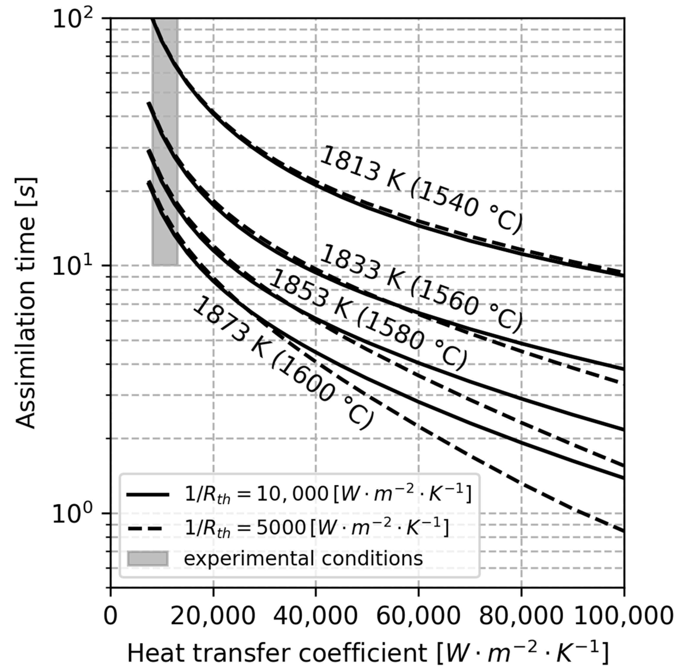
3.1. Estimations of Wire Residence Time in the Bath and Diameter of the Wire + Solidified Metal Shell Ensemble, Post Immersion

The total residence times of the wires in the bath during the experiment were determined from timestamps of the camera recordings taken during each immersion experiment. The total residence time of a wire in the bath during the experiment (texp) can be split into three distinct periods: the time taken to reach the maximum immersion depth (tim), the time that the wire was held at the maximum immersion depth (thold), and the time taken for the extraction of the wire from the bath (text).
t e x p = t i m + t h o l d + t e x t
The residence time of any given radial sections throughout the length of the wire can be estimated by considering Equations (1)–(4) and the schematic shown in Figure 5. From the measurements of the total length of the wire before immersion (Lbef), the total length of the wire after immersion (Laft), and the length of the non-immersed part of the wire (Lnim), the length of wire that was originally immersed in the melt (Lim) and the length of the wire + shell that was extracted from the melt (Lext) can be determined:
L i m = L b e f L n i m
L e x t = L a f t L n i m
Once the immersed length (Lim) and the extracted length (Lext) have been determined, an equation for estimating the total residence time of a radial section as a function of the immersed wire length, ttot(x), can be written assuming constant velocities of immersion and withdrawal:
t t o t x = t i m x L i m + t h o l d + t e x t x L e x t
After the immersion experiments, measurements of the diameter of the wire + shell ensemble were taken according to the procedure schematized in Figure 6. At given positions over the immersed length of the wire (x), the external diameter (2R) was measured with the aid of a vernier caliper. To account for irregularities in the shell, each measurement was repeated 10 times at random angular positions (i.e., the ensemble was rotated for each individual measurement), so that a statistical summary of the diameters could be obtained at each immersed length (x) at which measurements were performed. Under the assumption that the wires before immersion were perfectly cylindrical, with an internal diameter of the wire (2r) of 8.2 mm, the average thickness of the ensemble constituted by the casing and the solidified shell can be estimated as the difference between the external radius of the wire + shell ensemble (R) and the internal radius of the wire (r).
Table 3 presents a summary of the results of the estimations of the radiuses of the wire + shell ensembles for the six experiments (wires IVI). For each experiment, the estimation of the mean radius (Rmean) and descriptive statistics (Rstdev, Rmin, RQ1, RQ2, RQ3, Rmax: standard deviation, minimum, first quartile, second quartile (median), third quartile, and maximum, respectively) are listed along with the relative position of the immersed length (x) with respect to the bath surface (when the wire was held at maximum immersion depth) and the estimated total residence time for the corresponding immersed length (ttot(x)).

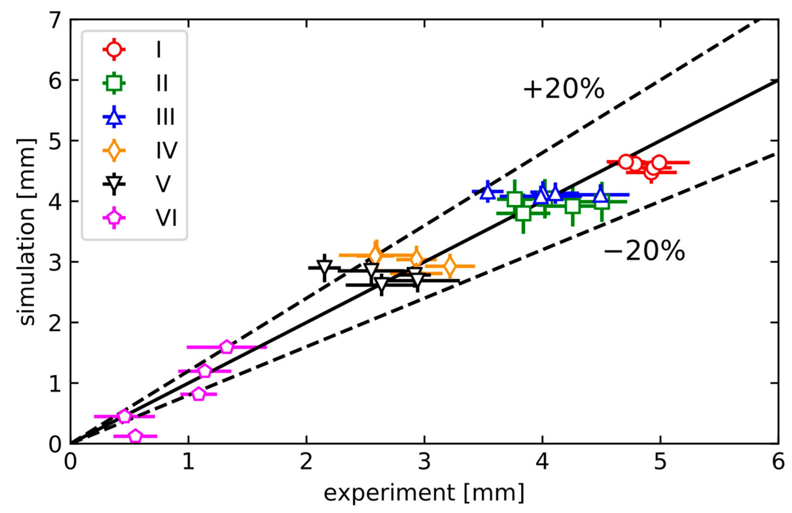
3.2. Comparison of Experimental Results and Numerical Simulations

Numerical simulations of the experiments of wire immersion were performed with a transient 1D (radial) thermal model of the assimilation of cored wire developed by the present authors [34,35]. The evolution of the position of the wire/melt interface given by simulations of the different immersion conditions was compared against the results presented in Table 3. In the simulations, the convective heat transfer coefficient was calculated using a natural convection correlation that is valid for flow past cylinders [41,42,43], shown in Equation (5). For all simulations, a bath cooling rate of 1 K∙s−1 was considered, based on the bath cooling rate observed during the experiments. Based on data from the literature [6,41,42], the magnitudes of the contact thermal resistances, Rth, used to account for discontinuities in the temperature profiles at the filler/casing and casing/shell interfaces, were both set to 1 × 10⁻⁴ or 2 × 10⁻⁴ m2∙K∙W−1. In reciprocal units, this corresponds to setting 1/Rth at the filler/casing and casing/shell interfaces to 10,000 or 5000 W∙m−2∙K−1, respectively.
N u x , c y l = N u x , p l a t e 0.2672   ε   P r 0.42 + 1.011   P r 0.02
with
N u x , p l a t e = 0.503   G r x   P r 1 + 0.492 P r 9 16 4 9
and
ε = 2 2 G r x 0.25 l r
where Nux,cyl: the Nusselt number for the vertical cylinder [-], Nux,plate: the Nusselt number for the vertical plate [-], ε: the transverse curvature parameter [-], Pr: the Prandtl number [-], Grx: the Grashof number [-], l: the immersed cylinder length [m], r: the radius of the cylinder [m].
Figure 7 presents, for all wires, a comparison between the radius of the wire + shell ensemble estimated from the experiments, and the evolution of the wire/melt interface from the simulations. The experimental results are shown by means of boxplots, where the green square markers correspond to the estimated mean values, and the whiskers of the boxplots correspond to the minimum and maximum values. The simulation results are plotted as gray regions bounded by two continuous black lines; they correspond to the range of positions of the wire/melt interface when 1/Rth is set between 5000 and 10,000 W∙m−2∙K−1. The horizontal lines at radius = 4.1 mm and 4.8 mm correspond to the reference position of the internal and external faces of the casing, respectively. For both the “low” (wires IIII) and “high” (wires IVVI) bath temperatures, there is reasonable agreement between the experiments and simulations. Discrepancies at “low” times could be attributed to border effects not considered by the model, given that measurements were performed at positions close to the bath surface during the immersion experiments. For the case of wire VI, the combination of the bath temperature and holding time-span near the leading edge of the wire led to the onset of the free-dissolution period, i.e., the onset of melting of the casing material, as already observed in the former section.
In Figure 8, the deviations between the simulations and experiments are plotted, with dashed lines marking the ±20% deviation range. In this plot, the thickness of the casing + shell ensemble is considered rather than the estimated radius of the wire + shell ensemble, which produces a tighter criterion for evaluating the deviations. The range of the error bars for the “experiment”-axis corresponds to the results shown in Table 3; for the “simulation”-axis, the range of the error bars corresponds to the change in thickness as the magnitudes of the contact thermal resistances are changed. Since the model matches the experimental conditions of the immersion of the cored wires, it is expected that simulations extrapolating to industrial processing conditions would allow for producing guidelines for optimization of the cored wire injection process, as a complement to established approaches that combine industrial trials with thermodynamic analyses [44,45,46,47,48,49,50,51,52,53,54,55].

4. Discussion

The transient 1D (radial) thermal model of the assimilation of cored wire developed by the present authors [34,35] was further used to gain insight into the effects of the bath temperature, convective heat-transfer coefficient, and magnitude of contact thermal resistances on the wire assimilation times. The wire configuration used in the lab-scale experiments was considered for these simulations, for which the bath temperatures were kept constant. The calculation results, presented as curves of the assimilation time vs. the heat transfer coefficient are shown in Figure 9. The sweep of magnitudes of the heat transfer coefficient spans from static bath conditions up to heavily stirred baths, such as in industrial furnaces [7,8].
As expected, the wire assimilation times are inversely proportional to both the bath temperature and the magnitude of the convective heat-transfer coefficient. At conditions with relatively low heat-transfer coefficients, corresponding to the natural convection static-bath conditions of the laboratory-scale experiments, the effect of the contact thermal resistances on the wire assimilation time is practically negligible. On the other hand, when the heat-transfer coefficient increases, such as in the conditions of forced convection seen in industrial furnaces (e.g., steel ladle), the effect of contact thermal resistances becomes non-negligible.
From a modeling standpoint [34,35], Equation (6) establishes that, during the assimilation of the cored wire, the movement of the wire/melt interface, i.e., a change in the volume of the solidified shell (during the shell period) of the steel casing (during the free-assimilation period), is governed by the balance between the convective heat flux from the melt to the interface (φconv) and the diffusive heat flux from the interface to the interior of the wire (φdiff).
ρ Δ H m d V d t = S φ d i f f φ c o n v  
with
φ d i f f = λ d T d r i n t
and
φ c o n v = h T b a t h T i n t
where ρ: the density [kg∙m−3], ΔHm: the latent heat of phase change [J∙kg−1], V: the volume [m3], t: the time [s], S: the surface area of the interface before interface movement step [m2], φconv: the convective heat flux [W], φdiff: the diffusive heat flux [W], λ: the thermal conductivity [W∙m−1∙K−1], h: the convective heat transfer coefficient [W∙m−2∙K−1], Tbath: the liquid steel bath temperature [K], and Tint: the wire/melt interface temperature [K].
When the magnitude of the contact thermal resistance Rth increases, i.e., 1/Rth decreases, at either the core/casing or the casing/shell interfaces, the diffusion of heat from the external layers of the wire towards the core of the wire is hindered. In this scenario, the external layers of the wire are heated up more readily, leading to shorter spans of the shell (due to contact resistance at the casing/shell interface) and free-assimilation periods (due to contact resistance at the core/casing interface), i.e., the assimilation of the cored wire occurs in shorter time-spans.

5. Conclusions

A laboratory-scale study was performed in which the kinetics of the assimilation of cored wire in liquid steel baths was studied. An original dataset of the positions of the wire/melt interface of cored wires (namely, the diameter of the ensemble constituted by the wire and a solidified metal shell) as a function of the time and steel bath temperature was produced. This dataset spans all of the shell periods up to the first moments of the free-dissolution period. The dataset was compared against simulations made with a transient 1D (radial) thermal model of the assimilation of cored wire, presented by the present authors, with reasonable agreement.
The dataset presented here is a valuable resource for the validation of future developments in the field of modeling of the assimilation of cored wires in liquid metal baths. With proper inputs, these kinds of models are used for producing guidelines for optimization of the process of the injection of cored wire. Some potential applications of interest are the individual adjustment of wire feeding speeds depending on the type of trimming addition performed in the steel ladle, the optimization of cored wire injection practice for the calcium treatment of steel to decrease reactivity and increase calcium recovery, and the optimization of cored injection practices in shallow vessels such as tundishes for continuous casting and shallow ladles for alloy modification in cast-iron and copper foundries.

Author Contributions

Conceptualization, E.-I.C.-C. and J.-P.B.; methodology, E.-I.C.-C., J.J. and J.M.; software, E.-I.C.-C., A.J. and J.-P.B.; validation, E.-I.C.-C.; formal analysis, E.-I.C.-C.; investigation, E.-I.C.-C., J.J. and J.M.; resources, J.-P.B. and A.J.; data curation, E.-I.C.-C.; writing—original draft preparation, E.-I.C.-C.; writing—review and editing, E.-I.C.-C. and J.-P.B.; visualization, E.-I.C.-C.; supervision, J.-P.B.; project administration, E.-I.C.-C. and J.-P.B.; funding acquisition, J.-P.B. and A.J. All authors have read and agreed to the published version of the manuscript.

Funding

This research was funded by Association Nationale de la Recherche et de la Technologie (CONVENTION CIFRE N° 2015/0443) and Affival SAS.

Data Availability Statement

The original contributions presented in the study are included in the article, further inquiries can be directed to the corresponding author.

Acknowledgments

The authors would like to thank Alexandre Carré, Director of Technologies at Affival SAS for providing cored wire casings for performing the experiments, and the valuable discussions during the preparation of this work.

Conflicts of Interest

Author Edgar-Ivan Castro-Cedeno was formerly employed by the company Affival SAS. The remaining authors declare that the research was conducted in the absence of any commercial or financial relationships that could be construed as a potential conflict of interest.

References

  1. Holappa, L. Secondary Steelmaking. In Treatise on Process Metallurgy, 1st ed.; Seetharaman, S., McLean, A., Guthrie, R., Seetharaman, S., Eds.; Elsevier: Oxford, UK, 2014; Volume 3A, pp. 301–346. [Google Scholar]
  2. Ren, Y.; Wang, W.; Yang, W.; Zhang, L. Modification of Non-Metallic Inclusions in Steel by Calcium Treatment: A Review. ISIJ Int. 2023, 63, 1927–1940. [Google Scholar] [CrossRef]
  3. Yang, W.; Zhang, L.; Ren, Y.; Chen, W.; Liu, F. Formation and Prevention of Nozle Clogging during the Continuous Casting of Steels: A Review. ISIJ Int. 2024, 64, 1–20. [Google Scholar] [CrossRef]
  4. Ototani, T. Calcium Clean Steel, 1st ed.; Springer: Berlin, Germany, 1986; pp. 20–33. [Google Scholar]
  5. Kor, G.J.W.; Glaws, P.C. Ladle Refining and Vacuum Degassing. In The Making, Shaping and Treating of Steel, 11th ed.; Fruehan, R.J., Ed.; AISE Steel Foundation: Warrendale, PA, USA, 1998; Steelmaking and Refining Volume; pp. 661–713. [Google Scholar]
  6. Argyropoulos, S.A.; Li, S. Kinetics of Assimilation of Additions in Liquid Metals. In Treatise on Process Metallurgy, 1st ed.; Seetharaman, S., McLean, A., Guthrie, R., Seetharaman, S., Eds.; Elsevier: Oxford, UK, 2014; Volume 2, pp. 359–426. [Google Scholar]
  7. Brabie, L.C.; Kawakami, M. Kinetics of Steel Scrap Melting in Molten Fe-C Bath. High. Temp. Mater. Process 2000, 19, 241–256. [Google Scholar] [CrossRef]
  8. Penz, F.M.; Schenk, J. A Review of Steel Scrap Melting in Molten Iron-Carbon Melts. Steel Res. Int. 2019, 90, 1900124. [Google Scholar] [CrossRef]
  9. Szekely, J.; Chuang, Y.K.; Hlinka, J.W. The Melting and Dissolution of Low-Carbon Steels in Iron-Carbon Melts. Metall. Trans. 1972, 3, 2825–3328. [Google Scholar] [CrossRef]
  10. Kim, Y.U.; Pehlke, R.D. Mass Transfer During Dissolution of a Solid into Liquid in the Iron-Carbon System. Metall. Trans. 1974, 5, 2527–2532. [Google Scholar] [CrossRef]
  11. Kim, Y.U.; Pehlke, R.D. Transient Heat Transfer During Initial Stages of Steel Scrap Melting. Metall. Trans. B 1975, 6, 585–591. [Google Scholar] [CrossRef]
  12. Wright, J.K. Steel Dissolution in Quiescent and Gas Stirred Fe/C Melts. Metall. Trans. B 1989, 20, 363–374. [Google Scholar] [CrossRef]
  13. Isobe, K.; Maede, H.; Ozawa, K.; Umezawa, K.; Saito, C. Analysis of the Scrap Melting in High Carbon Molten Iron. Tetsu-To-Hagane 1990, 76, 2033–2040. [Google Scholar] [CrossRef]
  14. Kawakami, M.; Takatani, K.; Brabie, L.C. Heat and Mass Transfer Analysis of Scrap Melting in Steel Bath. Tetsu-To-Hagane 1999, 85, 658–665. [Google Scholar] [CrossRef]
  15. Yamamura, H.; Mizukami, Y.; Ueshima, Y.; Miyazawa, K. Effect of Molten Steel Flow on Nonuniformity of Initially Solidified Shell. High. Temp. Mater. Process 2000, 19, 231–240. [Google Scholar] [CrossRef]
  16. Wei, G.; Zhu, R.; Tang, T.; Dong, K. Study on the Melting Characteristics of Steel Scrap in Molten Steel. Ironmak. Steelmak. 2019, 46, 609–617. [Google Scholar] [CrossRef]
  17. Xi, X.; Li, S.; Yang, S.; Zhao, M.; Li, J. Melting Characteristics of Steel Scrap with Different Carbon Contents in Liquid Steel. Ironmak. Steelmak. 2020, 47, 1087–1099. [Google Scholar] [CrossRef]
  18. Gao, M.; Gao, J.T.; Zhang, Y.L. Evaluation of Mass Transfer Coefficient during Scrap Melting. Metals 2021, 11, 1368. [Google Scholar] [CrossRef]
  19. Li, J.; Provatas, N. Kinetics of Scrap Melting in Liquid Steel: Multipiece Scrap Melting. Metall. Mater. Trans. B 2008, 39, 268–279. [Google Scholar] [CrossRef]
  20. Xi, X.; Chen, S.; Yang, S.; Ye, M.; Li, J. Melting Characteristics of Multipiece Steel Scrap in Liquid Steel. ISIJ Int. 2021, 61, 190–199. [Google Scholar] [CrossRef]
  21. Arzpeyma, N.; Windlund, O.; Ersson, M.; Jönsson, P. Mathematical Modeling of Scrap Melting in an EAF Using Electromagnetic Stirring. ISIJ Int. 2013, 53, 48–55. [Google Scholar] [CrossRef]
  22. Kruskopf, A. A Model for Scrap Melting in Steel Converter. Metall. Mater. Trans. B 2015, 46, 1195–1206. [Google Scholar] [CrossRef]
  23. Deng, S.; Xu, A.; Yang, G.; Wang, H. Analyses and Calculation of Steel Scrap Melting in a Multifunctional Hot Metal Ladle. Steel Res. Int. 2019, 90, 1800435. [Google Scholar] [CrossRef]
  24. Chen, Y.; Ryan, S.; Silaen, A.K.; Zhou, C.Q. Simulation of Scrap Melting Process in an AC Electric Arc Furnace: CFD Model Development and Experimental Validation. Metall. Mater. Trans. B 2022, 53, 2675–2694. [Google Scholar] [CrossRef]
  25. Chen, Y.; Ryan, S.; Silaen, A.K.; Zhou, C.Q. An Investigation into EAF Burner Preheating and Melting Characteristics: CFD Model Development and Experimental Validation. Metall. Mater. Trans. B 2023, 54, 1068–1087. [Google Scholar] [CrossRef]
  26. Singha, P. Scrap Dissolution effect in BOF Converter Process. Ironmak. Steelmak. 2023, 50, 1434–1442. [Google Scholar] [CrossRef]
  27. Zhang, L.; Oeters, F. Melting and Mixing of Alloying Agents in Steel Melts: Methods of Mathematical Modeling, 2nd ed.; Verlag Stahleisen GmbH: Dusseldorf, Germany, 2006; pp. 1–59. [Google Scholar]
  28. Wang, Y.; Karasev, A.; Park, J.H.; Jönsson, P.G. Non-metallic Inclusions in Different Ferroalloys and Their Effect on the Steel Quality: A Review. Metall. Mater. Trans. B 2021, 52, 2892–2925. [Google Scholar] [CrossRef]
  29. Wang, Y.; Karasev, A.; Jönsson, P.G. Characterization of Nonmetallic Inclusions in Different Ferroalloys used in the Steelmaking Processes. Steel Res. Int. 2021, 92, 2100269. [Google Scholar] [CrossRef]
  30. Bannenberg, K.; Harste, K.; Bode, O. Aufschmelzverhalten von Fülldrähten Während des Einspulens. Stahl. Eisen 1992, 12, 101–107. [Google Scholar]
  31. Du Terrail, Y.; Fautrelle, Y.; Rebiere, M.; Quemener, O. Predictions of Melting or Dissolution Times with a 1D Heat Transfer Simulation Package. Trans. Eng. Sci. 1994, 5, 209–216. [Google Scholar]
  32. Sanyal, S.; Chandra, S.; Kumar, S.; Roy, G.G. An Improved Model of Cored Wire Injection in Steel Melts. ISIJ Int. 2004, 44, 1157–1166. [Google Scholar] [CrossRef]
  33. Sanyal, S.; Chandra, S.; Kumar, S.; Roy, G.G. Dissolution Kinetics of Cored Wire in Molten Steel. Steel Res. Int. 2006, 77, 542–549. [Google Scholar] [CrossRef]
  34. Castro-Cedeno, E.I.; Jardy, A.; Carré, A.; Gerardin, S.; Bellot, J.P. A Thermal Model of Cored Wire Injection. In Proceedings of the Liquid Metal Processing and Casting Conference LMPC 2017, Philadelphia, PA, USA, 10–13 September 2017. [Google Scholar]
  35. Castro-Cedeno, E.I.; Jardy, A.; Carré, A.; Gerardin, S.; Bellot, J.P. Thermal Modeling of the Injection of Standard and Thermally Insulated Cored Wire. Metall. Mater. Trans. B 2017, 48, 3316–3328. [Google Scholar] [CrossRef]
  36. Castro-Cedeno, E.I.; Carré, A.; Lujan, J. Advances in Cored Wire Injection and Calcium Treatment in Steelmaking. In Proceedings of the Iron & Steel Technology Conference, AISTech 2022, Pittsburgh, PA, USA, 18 May 2022. [Google Scholar]
  37. Huang, H.G.; Yan, M.; Sun, J.N.; Du, F.S. Heat transfer of Calcium Cored Wire and CFD Simulation on Flow and Mixing Efficiency in the Argon-Stirred Ladle. Ironmak. Steelmak. 2017, 45, 626–634. [Google Scholar] [CrossRef]
  38. Jingang, L.; Shuomeng, S.; Weihua, W.; Zhanjun, L.; Rensheng, C.; Ning, H. Study on Heat Transfer Mechanisms of Pure Calcium Cored Wire in Molten Steel by Feeding Rate. Metal. Ital. 2019, 111, 13–19. [Google Scholar]
  39. Guo, Q.; Chen, M.; Xu, L. Heat Transfer and Melting Characteristics of Calcium-Cored Wire in Molten Steel. Steel Res. Int. 2023, 95, 2300249. [Google Scholar] [CrossRef]
  40. Wang, H.; Shi, Y.; Su, J. An Improved Simulation Modelling on the Heat Transfer Process of Wire-Feeding Spheroidization in Iron Melt. Ironmak. Steelmak. 2023, 50, 392–401. [Google Scholar] [CrossRef]
  41. Mucciardi, F.A. Heat Flow to Cylinders Submerged in Liquid Metal Baths. Master’s Thesis, McGill University, Montreal, QC, Canada, 1977. [Google Scholar]
  42. Argyropoulos, S.A. The Kinetics of Ferro-Alloy Solution in Liquid Steel. Master’s Thesis, McGill University, Montreal, QC, Canada, 1977. [Google Scholar]
  43. Argyropoulos, S.A. Dissolution of High Melting Point Additions in Liquid Steel. Ph.D. Thesis, McGill University, Montreal, QC, Canada, 1981. [Google Scholar]
  44. Geng, R.; Li, J.; Shi, C. Evolution of Inclusions with Ce Addition and Ca Treatment in Al-killed Steel during RH Refining Process. ISIJ Int. 2021, 61, 1506–1513. [Google Scholar] [CrossRef]
  45. Liu, C.; Kacar, Y.; Webler, B.; Pistorius, P.C. Chemical Composition Modification of Inclusions in Steels by Controlled Ca Treatment. Metall. Mater. Trans. B 2021, 52, 2837–2841. [Google Scholar] [CrossRef]
  46. Sun, H.; Yang, J. Evolution Behaviour and Modification Mechanism of Inclusions in NM500 Wear-Resistant Steel with Calcium Treatment. Ironmak. Steelmak. 2022, 49, 795–812. [Google Scholar] [CrossRef]
  47. Castro-Cedeno, E.I.; Carré, A.; Bustos-Canairca, A.A. Calcium addition cleanliness and its potential effects on steel quality. In Proceedings of the 52 Seminário de Acieria, Fundicao e Metalurgia de Nao-Ferrosos, ABM Week 2023, Sao Paolo, Brasil, 3 August 2023. [Google Scholar]
  48. Zhang, T.; Cheng, G.; Yang, X.; Chen, X.; Pan, J.; Li, J.; Huang, Y.; Li, S. Evolution Mechanism of Ca-Containing Inclusions in 20Mn23AlV High-Manganese Non-Magnetic Steel During the Refining Process. Ironmak. Steelmak. 2023, 50, 266–272. [Google Scholar] [CrossRef]
  49. Xie, Y.; Meng, X.; Deng, X.; Li, S. Evolution of Sulphide Inclusion in Mg-Ca Treating Gear Steel. Ironmak. Steelmak. 2023, 50, 592–598. [Google Scholar] [CrossRef]
  50. Zhao, B.; Wu, W.; Zhi, J.; Su, C.; Zhang, J. Study on the Formation Mechanism of Clogging Layer of Rare Earth Microalloyed Q355 Steel’s Submerged Entry Nozzle and Process Optimization. Ironmak. Steelmak. 2023, 50, 782–793. [Google Scholar] [CrossRef]
  51. Chen, Z.; Pu, G.; Cai, B.; He, S.; Du, W.; Huang, H.; Chen, Y. Evolution mechanism of inclusions during refining and continuous casting process of 321 H stainless steel. Ironmak. Steelmak. 2023, 50, 837–847. [Google Scholar] [CrossRef]
  52. Li, X.; Wang, N.; Chen, M.; Du, Z. Effect of Molten Steel Composition on Inclusion Modification by Calcium Treatment in Al-Killed Tinplate Steel. ISIJ Int. 2023, 63, 303–312. [Google Scholar] [CrossRef]
  53. Zhong, H.; Jian, M.; Wang, Z.; Zhen, X.; Zhan, H.; Li, T.; Wang, X. Formation and Evolution of Inclusions in AH36 Steel During LF-RH-CC Process: The Influences of Ca-Treatment, Reoxidation, and Solidification. Metall. Mater. Trans. B 2023, 54, 593–601. [Google Scholar] [CrossRef]
  54. Zhou, Q.; Ba, J.; Chen, W.; Zhang, L. Evolution of Non-Metallic Inclusions in a 303-ton Calcium-Treated Heavy Ingot. Metall. Mater. Trans. B 2023, 54, 1565–1581. [Google Scholar] [CrossRef]
  55. Samiraj, A.R.; Haidar, S.K.; Pande, M.M.; Hazra, S.S. Optimizing Ferrotitanium Wire Injection Parameters for Improving Titanium Recovery in Ladle Furnace Steelmaking. Steel Res. Int. 2024, in press. [CrossRef]
Figure 1. Schematic representation of possible assimilation routes for cored wires immersed into liquid steel.
Metals 14 00462 g001
Figure 2. Schematic of experimental apparatus used for the experiments of the immersion of cored wire into liquid steel baths.
Metals 14 00462 g002
Figure 3. Photograph of extraction of wire V from the bath during the immersion experiment. Notice the shell of solidified bath material around the cored wire.
Metals 14 00462 g003
Figure 4. Cored wires with solidified metal shell after wire immersion experiments at various initial steel bath temperatures: (a) wire I (1818 K); (b) wire II (1823 K); (c) wire III (1823 K); (d) wire IV (1853 K); (e) wire V (1858 K); (f) wire VI (1873 K).
Metals 14 00462 g004
Figure 5. Schematic of the wire + solidified shell ensemble post-immersion. The immersion times of radial sections throughout the length of the wire can be estimated using Equations (1)–(4), using the measured length of wire before immersion (Lbef), length of wire after immersion (Laft), length of non-immersed part of the wire (Lnim), and timestamps of camera recordings (tim, thold, text).
Metals 14 00462 g005
Figure 6. Schematic of the procedure for measuring the diameter of the wire + shell ensemble post-immersion. To obtain estimations of mean diameter, the specimen was rotated for each of the 10 individual measurements taken at fixed wire lengths.
Metals 14 00462 g006
Figure 7. Comparison of estimations of radius of the wire + shell ensemble (experimental) and computed evolution of the wire/melt interface (simulations): (a) wire I (1818 K); (b) wire II (1823 K), (c) wire III (1823 K); (d) wire IV (1853 K); (e) wire V (1858 K); (f) wire VI (1873 K).
Metals 14 00462 g007
Figure 8. Deviations between estimations of thickness of the casing + shell ensemble (experimental) and thicknesses from the computed evolution of the wire/melt interface (simulations).
Metals 14 00462 g008
Figure 9. Extrapolations of wire assimilation times for cored wire used in the lab-scale experiments, as a function of bath temperature, convective heat transfer coefficient, and magnitude of contact thermal resistances.
Metals 14 00462 g009
Table 1. Nominal compositions of the iron powder used as wire filler, the steel sheath of the wire casing, and the steel bath material for the cored wire immersion experiments, in wt%.
MaterialCMnSiPSOFe
Wire filler0.003 0.114Bal
Wire casing0.070.250.0150.010.009 Bal
Steel bath<0.0020.03<0.001<0.005<0.01 Bal
Table 2. Initial bath temperature (Tbath,ini) and bath superheat (ΔTin) in the cored wire immersion experiments.
WireTbath,iniΔTini
I1818 K (1545 °C)11 K
II1823 K (1550 °C)16 K
III1823 K (1550 °C)16 K
IV1853 K (1580 °C)46 K
V1858 K (1585 °C)51 K
VI1873 K (1600 °C)66 K
Table 3. Statistical summary of estimations of radius of the wire * + shell ensemble, ttot(x) is given in s, and x, Rstdev, Rmin, RQ1, RQ2, RQ3, Rmax are given in mm.
Wirettot(x)xRmeanRstdevRminRQ1RQ2RQ3Rmax
I
(1818 K)
7.3238.59.020.238.688.839.069.189.35
8.26489.040.168.858.989.029.089.42
9.34598.890.248.588.678.939.089.20
9.8864.59.090.278.588.979.179.299.42
10.22688.810.178.548.718.828.909.06
II
(1823 K)
4.8337.940.247.447.847.958.018.29
5.843.58.360.237.988.248.338.488.79
6.8548.60.228.428.468.508.798.97
7.94667.870.167.627.747.927.988.07
8.89768.120.237.857.958.108.248.52
III
(1823 K)
10.6916.57.640.147.517.517.577.777.83
11.45268.10.117.948.018.128.178.28
12.3737.58.210.217.848.098.178.358.62
13.52528.590.268.228.378.578.838.92
14.64668.090.377.577.738.168.448.49
IV
(1853 K)
4.46236.70.346.356.406.606.917.36
5.32336.680.176.436.536.736.826.88
6.18447.030.186.706.957.097.167.23
7.16547.320.226.867.197.337.517.55
7.98697.030.246.476.977.077.177.29
V
(1858 K)
5.81156.250.155.986.226.266.366.45
6.2225.56.650.36.326.426.586.797.22
6.71387.020.156.796.926.987.237.23
7.3153.570.386.386.737.057.237.53
7.7163.56.750.336.346.456.786.957.38
VI
(1873 K)
8.0813.55.420.365.025.135.335.755.90
9.24235.240.244.905.025.305.415.57
10.2731.55.190.164.815.145.175.325.38
11.3740.54.560.274.134.364.584.824.84
12.2247.54.650.24.284.604.704.784.88
* The internal and external radiuses of the wires were 4.1 mm and 4.8 mm, respectively.
Disclaimer/Publisher’s Note: The statements, opinions and data contained in all publications are solely those of the individual author(s) and contributor(s) and not of MDPI and/or the editor(s). MDPI and/or the editor(s) disclaim responsibility for any injury to people or property resulting from any ideas, methods, instructions or products referred to in the content.

