Article

Microstructure Evolution and Strengthening Mechanisms of Mg–Steel Welds Subjected to Multiple Microshot Peening Treatment

1
Department of Mechanical Engineering, Taiyuan Institute of Technology, Taiyuan 030008, China
2
College of Materials Science and Engineering, Yangtze Normal University, 16# Juxian Avenue, Fuling District, Chongqing 408100, China
3
College of Materials Science and Engineering, Chongqing University, 174# Shazheng Street, Shapingba District, Chongqing 400044, China
*
Author to whom correspondence should be addressed.
Metals 2024, 14(4), 470; https://doi.org/10.3390/met14040470
Submission received: 18 March 2024 / Revised: 11 April 2024 / Accepted: 15 April 2024 / Published: 17 April 2024

Abstract

:
A surface modification through multiple microshot peening (MSP) was performed on Mg–steel weldment. Application of MSP was found beneficial to the elimination of surface microdefects owing to severe plastic deformation induced by MSP. Moreover, MSP treatment transformed the residual tensile stress of the weld surface into residual compressive stress, which was beneficial to inhibit the initiation and propagation of surface microdefects. Strain strengthening and grain refining were introduced into the shot peened joint, resulting in the notable increase in surface hardness and tensile strength. Compared with an untreated joint, the tensile strength of optimized Mg/steel weldment was markedly enhanced and raised 28% to 244 MPa, and fracture ultimately occurred in the Mg alloy base material. Moreover, the refinement of weld grain induced by MSP treatment was beneficial to strengthen the stress corrosion sensitivity of Mg/steel joints, while also promoting the formation of a denser Mg(OH)2 passivation film on the weld surface and enhancing the corrosion resistance of the joints.

1. Introduction

In recent years, the heterogeneous metal welding of Mg–steel has attracted growing attention, considering the advantages of the two metals and the potential characteristics of the welded parts. Similar to common welding of dissimilar metals, it is hard to achieve reliable joining of Mg–steel due to the huge gaps in physical, chemical, and metallurgical performances [1,2,3].
According to the previous studies, various surface strengthening treatments including laser melting [4], thermal spraying [5], electrochemical deposition [6,7], and chemical and physical vapor deposition [8,9,10] have been extensively investigated. Although some achievements have been made, there are still some deficiencies. Shot peening (SP) technology is one of the preferred surface strengthening processes and draws broad attention owing to its low cost and easy operation [11,12,13,14,15]. SP is a mechanical surface modification technique dependent on the impact effect of projectiles on the component surface. During the peening process, the moving projectile repeatedly hits the component surface and material surface experiences severe plastic deformation, which eventually leads to strain strengthening. Studies reveal that the SP technique has numerous advantages in terms of fatigue, microstructure, corrosion, mechanical properties, and residual stress distribution [16,17,18,19,20]. For example, Zhang et al. [21] indicated that the surface shot peening treatment of AZ80 Mg alloy can inhibit the initiation and propagation of surface cracks, refine grains, induce compressive residual stresses, and produce a surface strain hardening effect. Xie et al. [22] studied the effects of SP on Ti6Al4V alloy and reported that the microhardness increased noticeably and residual compressive stress was introduced into the weld surface, which eventually led to a 27% improvement in mechanical properties. Kovaci et al. [23] pointed out that a plastic deformed area was formed on AlSi 4140 steel after SP treatment, with an expanded and refined microstructure. Electrochemical detection revealed that the corrosion resistance of the material increased with the enhanced SP pressure owing to the formation of refined grains and subgrains. Harada et al. [24] studied the influences of projectile size on peening strengthening and reported that the reduction of projectile size would increase the surface residual compressive stress and decrease the surface roughness. For components with high surface quality requirements, the above treatment method is expected to eliminate the negative effect of roughness on mechanical performances.
However, although excessive shot peening pressure can refine the weld structure, it tends to produce defects such as cracks inside the joint. In the present study, shot peening treatment with various passes was performed on Mg–steel weldment. The effects of the SP pass on surface morphology, microstructure, stress, mechanical performances, and corrosion features were investigated and discussed.

2. Materials and Experiment Procedures

Commercially available AZ41M alloy and galvanized steel were selected in this study. The main chemical composition of as-received AZ41M plate was Al 4.1, Mn 0.3, Zn-0.9, Si 0.1 (wt.%), and balanced Mg. The main chemical constituents of galvanized steel were Mn 0.6, C 0.05, Si 0.05 (wt.%), and balanced Fe. The basic dimensions of the base material were 60 mm × 60 mm × 1.5 mm. The filler material was AZ41 Mg-based alloy wire (Al 4.1, Mn 0.3, Zn 0.9, Si 0.1 in wt.%, balanced Mg) measuring 1.0 mm in diameter. The sound Mg–steel lap joint was obtained by a TIG welding unit (YC-300WP5HGN, PWST) with optimal welding settings, i.e., current of 70A, voltage of 12 V, welding rate of 3.3 mm/s, and wire feed rate of 6.7 mm/s. After the TIG welding process, all specimens were slightly ground with SiC paper (2000 grit) and subsequently ultrasonically cleaned in ethyl alcohol for 1 min.
The shot peening treatment of the specimen surface was conducted by a compressed air shot blasting machine (6050B, Rongzhuo, Chongqing, China). Figure 1 illustrates the schematic diagram of the shot peening process and strengthening mechanism. The peening equipment mainly includes a control system, spray gun, sand bucket, and air compressor. Spherical stainless steel projectiles were used in the shot peening treatment. Figure 1a shows that numerous projectiles bombarded the specimen surface continuously under the action of compressed air. Under the continuous impact of projectiles, a plastic deformation layer appeared on the surface of the weld and it experienced high strain inside, as presented in Figure 1b. Table 1 lists detailed parameters of the shot peening treatment. Several groups of experiments with different shot peening passes were set up to explore the effect of MSP intensity on the microstructure evolution and mechanical performance of Mg–steel samples, as shown in Table 2.
After shot peening treatment, a series of samples for a tensile test and microstructure and microhardness analysis were cut from the center area of the weldment, as presented in Figure 2. A tensile testing machine (AG-X, SHIMADZU, Osaka, Japan) was applied to reveal the joint strength with the tensile velocity of 1.5 mm/min. The surface morphology and weld microstructure were studied through an optical microscope (Axiovert 40 MAT, Zeiss, Jena, Germany), transmission electron microscopy (TECNAI G2 F20, FEI, Hillsboro, OR, USA), and field emission scanning electron microscopy (JSM-7800F, JEOL, Akishima shi, Japan). The microhardness distributions of the Mg/steel weld along the depth were measured by a Vickers hardness tester with the load of 50 g and duration of 15 s. Additionally, the residual stress distribution in the weld zone was measured by an X-ray stress detector with Cu-Ka radiation on the basis of the sin2Ψ principle. The surface roughness of the shot peening specimen was measured by the profile measurement method. Stress corrosion cracking tests were carried out on a slow strain rate tensile machine in 3.5 wt.% NaCl solution with a fixed strain rate of 2.2 × 10⁻⁵ mm/s.

3. Results and Discussion

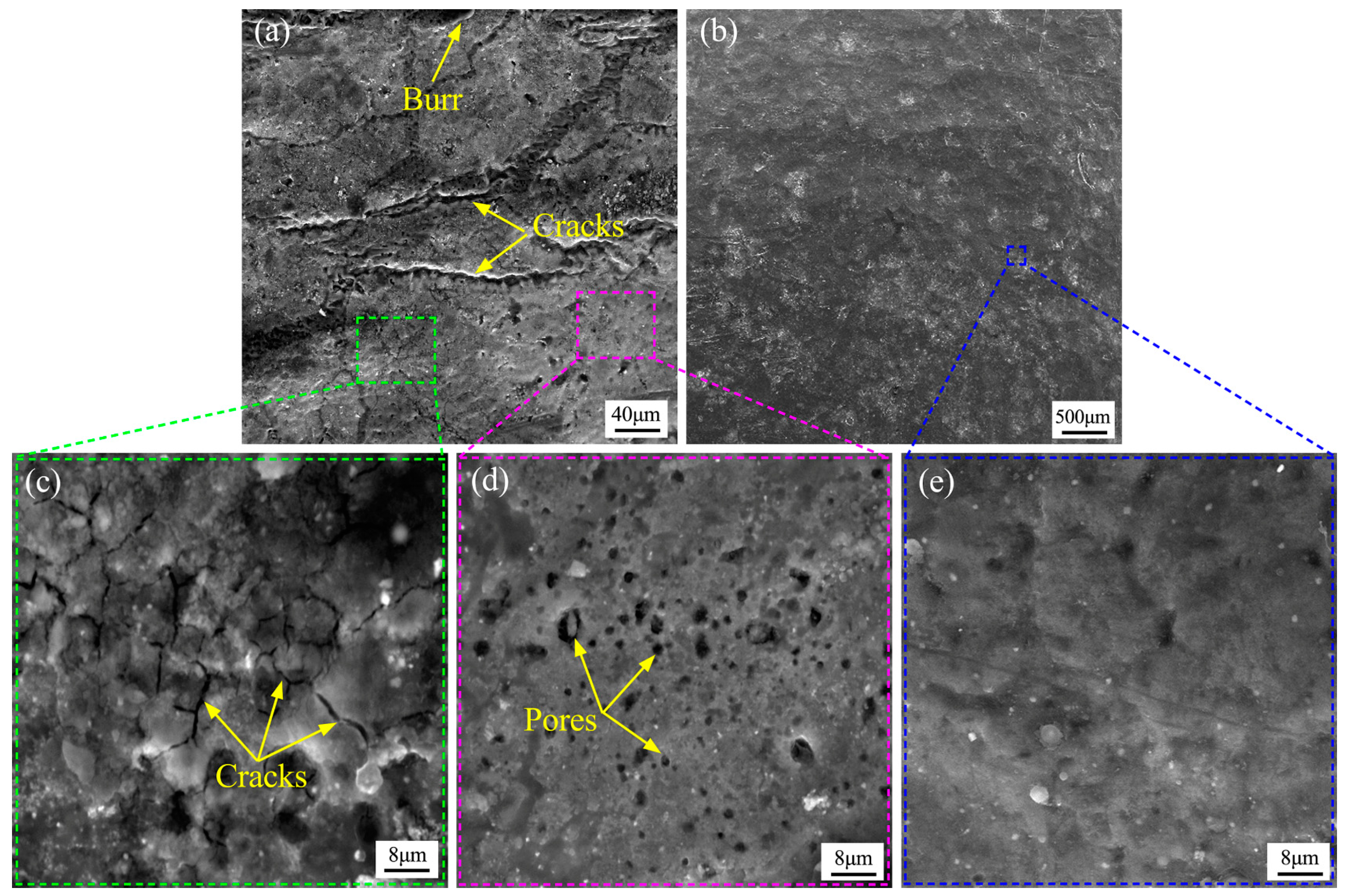
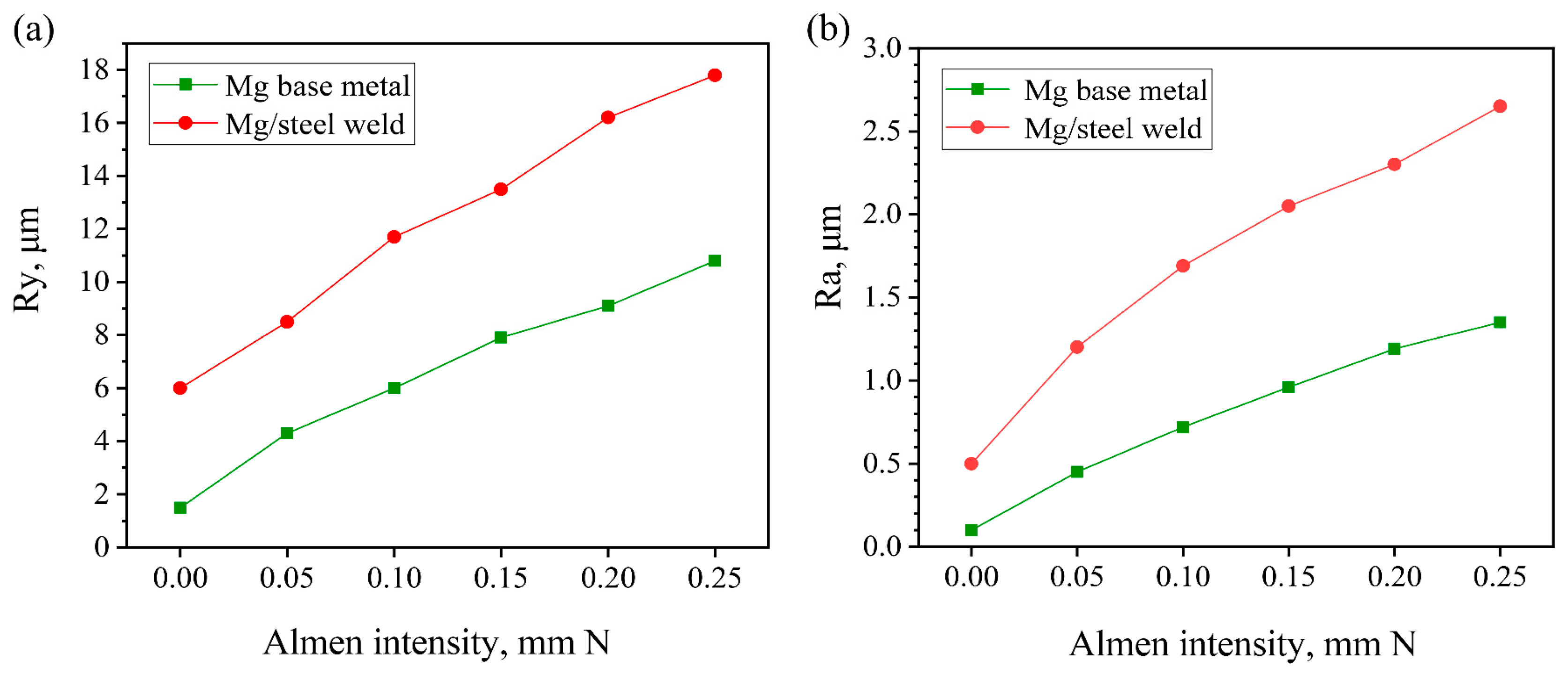
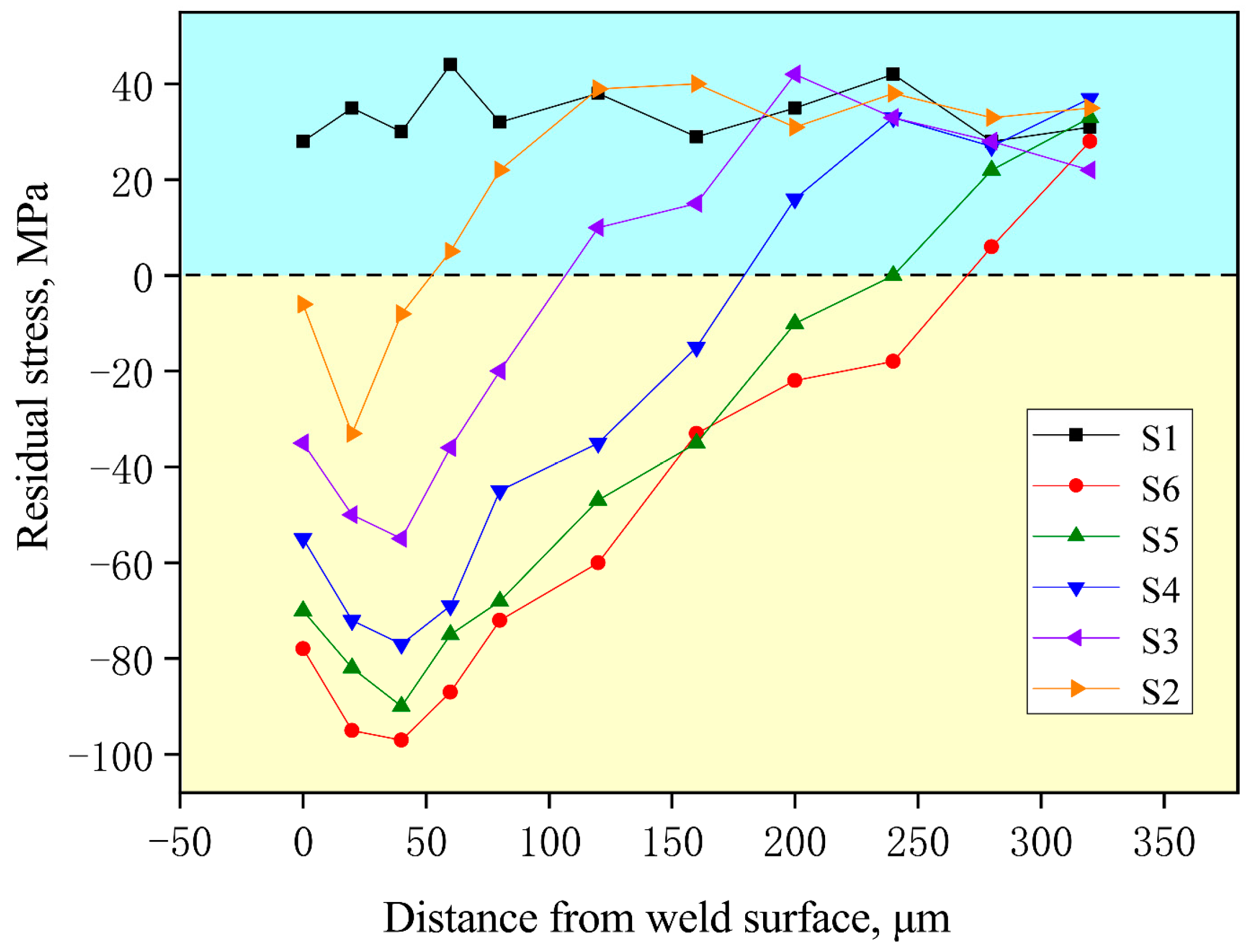
3.1. Weld Surface Morphology and Stress Distribution

Figure 3 shows the typical upper surface microstructure of the weldment obtained with and without shot peening. For the non-shot peened specimen, the surface of the weld bead was rough and uneven, even with a small amount of burrs, as presented in Figure 3a. Figure 3c,d reveal that some microcracks and pores were formed on the surface of the weld bead. Research shows that the surface morphology of a weld is related to the cooling and solidification process of the molten pool. Before the pool solidified, molten metal absorbed hydrogen to form a hydrogen pore. Subsequently, the hydrogen pore floated up under the buoyancy of the molten pool. However, the temperature of the liquid phase decreased rapidly at the later stage of solidification and resulted in the increase in viscosity. At the end of molten pool solidification, some hydrogen bubbles were subjected to a large viscous force, which may be locked just at the moment of escaping from the weld surface, thus forming pores (pits and burrs). In addition, the arc area on the surface of the weld bead would shrink due to the temperature reduction, leading to the occurrence of microcracks. Similar results have been reported in the high-energy shot peening process of Mg alloy [25]. There is no doubt that the above surface defects will lead to premature failure of Mg–steel joints during service. Figure 3b shows the typical surface morphology of weldment under shot peening treatment. It can be found that the surface of the weld bead was full of traces of projectile impact. The shot peening process not only changed the surface morphology but also prompted closure of surface defects, as presented in Figure 3e. According to Dekhtyar et al. [26], during shot peening treatment, the surface metal underwent severe plastic deformation under the repeated impact of the projectile, which induced shear stress around the pores and finally made the pores deform or even close.
The surface roughness measurement results of the weld and base metal after MSP treatment are shown in Figure 4, including the maximum profile height Ry and the arithmetic average roughness Ra. The surface roughness (Ry and Ra) of the weld and base metal both significantly increased with the increase in Almen intensity, indicating that significant plastic deformation occurred on the surface of the material with the increase in Almen intensity. In addition, Figure 4 presents that the surface roughness of the Mg alloy parent metal was lower than that of the weld surface under the same shot peening strength. The literature reveals that the surface roughness depends on the original crystallite dimension and hardness of the alloy, i.e., a finer grain and higher hardness value contribute to lower surface roughness [27]. Therefore, the sharp increase in the surface roughness of the weld also reveals that the microstructure of the weld has been severely coarsened compared with that of the base material, which will be analyzed in detail later. In addition, with the increase in Almen intensity to 0.25 mm N, the plastic deformation caused by excessive shot peening strength may lead to serious residual stress in the weld.
The residual stress distribution in the weld zone was measured by XRD technology and the detection results are illustrated in Figure 5. In order to determine the residual stress distribution, the lattice strain is evaluated in all directions and the relationship between sin2ψ and εøψ is derived. In the formula, the included angle between the reference direction and the stress measurement direction on the plane is ϕ . εøψ refers to the strain in the direction of ψ and ϕ , which is defined by the following formula [28]:
ε ϕ ψ = 1 + ν E σ ϕ s i n 2 ψ ν E σ 1 + σ 2
where υ is Poisson’s ratio (0.34); E is the elastic modulus (44 GPa); σ ϕ is the surface stress with an ϕ angle to the principal stress direction; σ1 and σ2 are principal stresses.
Then, the slope m of sin2ψ and εøψ can be calculated based on the relation between sin2ψ and εøψ, and the residual stress can be obtained by substituting m into the following formula [28]:
σ ϕ = m E 1 + ν
It can be found that a residual tensile stress of 28 MPa was detected on the weld surface of non-shot-peened weldment (Joint S1). It is worth noting that the surface residual tensile stress induced the initiation and expansion of surface microcracks at the end of weld solidification. On the other hand, during the tensile test, the residual tensile stress superimposed with tensile force, leading to premature fracture of weldment and reduced welding strength. For the shot-peening-treated samples, the residual tensile stress transformed into compressive stress and increased with the increase in peening passes, as presented in Figure 5. This is primarily because the plastically stretched surface area tended to expand while the adjacent elastically responding area below and around the projectile impact inhibited the expansion. In consequence, the residual compressive stress appeared on the surface of the weld bead. It has also been reported that the appearance of residual compressive stress is beneficial to the inhibition of surface microdefect initiation [29]. It can be concluded that the elimination of weld surface defects and the introduction of surface compressive stress were beneficial to enhance the tensile strength of Mg–steel weldment.

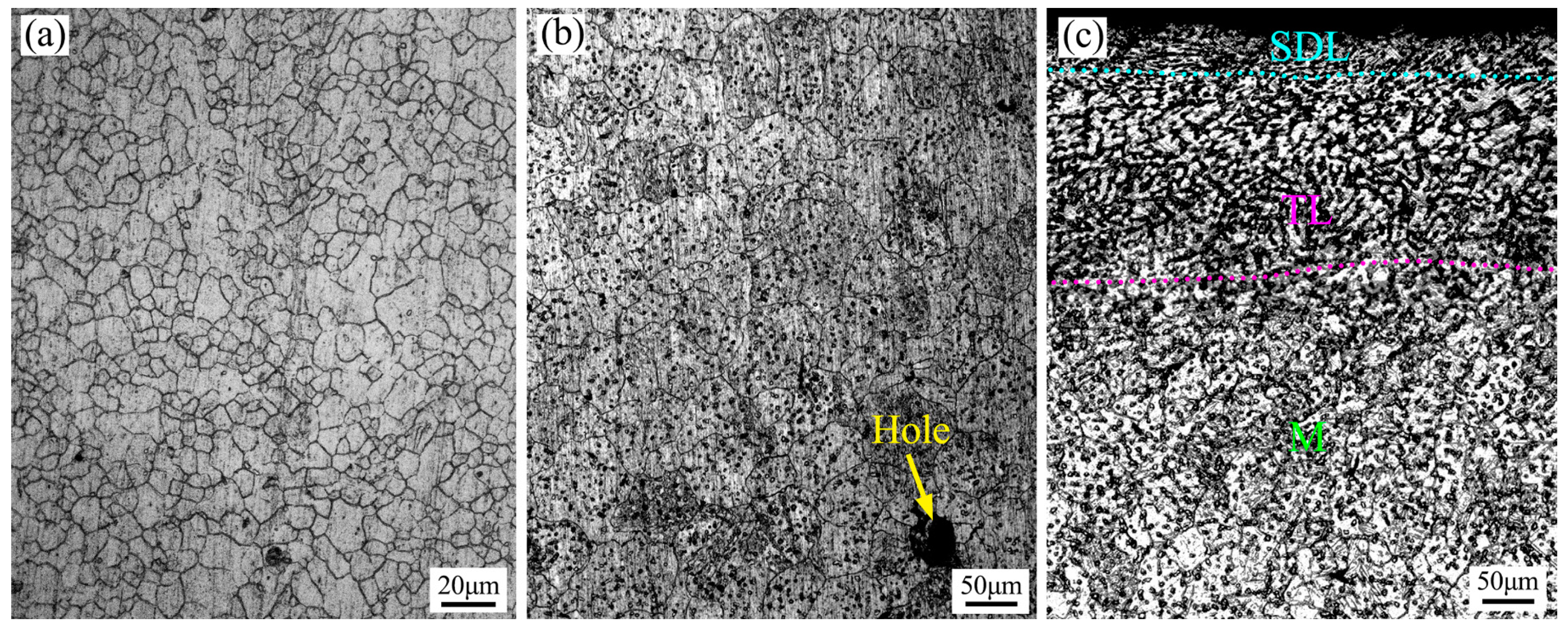
3.2. Weld Microstructure

Figure 6a shows that the AZ41M base material has fine grains and an approximately equiaxed crystal shape. Figure 6b,c show the typical metallographies of the upper surface layer of the Mg–steel weld. For traditional Mg–steel TIG joints (S1), the average grain size of the weld increased to about 62 μm, accompanied by holes, as illustrated in Figure 6b. For shot peened Mg–steel joints (S5), evidence of severe plastic deformation can be observed on the weld surface, while grain boundaries and β-Mg17Al12 phase cannot be identified in the metallographic structure of the weld surface, as shown in Figure 6c. Figure 6c reveals that the metallographic structure of the weld surface layer was divided into three parts from bottom to top: matrix (M), transition layer (TL), and severe deformation layer (SDL). Table 3 lists the thickness of SDL and TL under different shot peening intensities. It can be found that the thickness of the SDL layer was about 50 μm with Almen intensity of 0.20 mm N and its grain size had been significantly reduced compared to the M. TL was located between the SDL and M and presented a certain degree of microstructure refinement, owing to weakened projectile impact.
The average crystallite size and lattice distortion are calculated based on X-ray diffraction technology, and the results are presented in Figure 7. The calculation results reveal that the surface grains of the weld are obviously refined after MSP treatment, and the crystallite size reaches nanoscale. With the Almen intensity of 0.25 mm N (Joint S6), the weld surface has a minimum crystallite size of 50.5 nm, and the lattice distortion reaches 0.420. When the Almen intensity is in the range of 0–0.20 mm N (Joint S1–S4), the crystallite size of the weld surface gradually decreases with the increase in shot peening intensity, while the lattice distortion degree continues to increase. When the Almen strength exceeds 0.20 mm N, the crystallite dimension and lattice distortion values tend to be basically constant and no longer change with the increase in shot peening strength, which may be due to the formation of stable nanocrystalline structures. The above results indicate that the MSP process causes severe plastic deformation of the weld, and the deformation degree basically increases with the increase in shot peening strength.
However, the metallographic diagram reveals that β-Mg17Al12 phase cannot be identified in the severe deformation layer of the weld surface, indicating that the β phase may be almost dissolved in the Mg matrix. The above experimental results show that the diffusion of Mg–Al solid solution is abnormally fast during the MSP process, which is mainly due to the appearance of fine grain structure and the high stress generated during deformation [25]. The transformation of precipitated phase can be considered as the result of chemical disorder caused by plastic deformation, that is, Al dissolved in Mg matrix to form supersaturated solid solution. The literature indicates that the stress from the grain boundary is as high as 1/10 G when the weld undergoes MSP treatment, where G is the shear modulus of the material [30]. High stress was also widely present in the interior of grains, which was difficult to relax effectively due to the lack of volume dislocation. Therefore, high-stress distribution may lead to rapid volume diffusion [30]. The volume diffusion coefficient Dv can be calculated by the following formula:
4 D v t = d 2
where t is the MSP treatment time (maximum is 300 s) and d is the average grain size (approximately 50 nm). By substituting the values of t and d, the calculated Dv was approximately equal to 2.08 × 10⁻¹⁴ cm2/s. However, the literature indicates that the diffusion volume coefficient of Al in Mg is 3.5 × 10⁻²⁴ cm2/s at 300 k [31]. Meanwhile, the average crystallite dimension in the weld surface layer decreased to about 50 nm for joints subjected to the optimal MSP treatment. The increase in lattice distortion and stored energy was conducive to atomic diffusion, which eventually led to relatively rapid grain boundary diffusion and volume diffusion during MSP processing.
Figure 8 presents the corresponding TEM field images of the SDL of a Mg–steel joint under varied shot peening parameters. It can be found that some approximately equiaxed grains were formed in the weld bead, as shown in Figure 8a,b. These grains were about 50–75 nm in size and were randomly distributed. In addition, Figure 8 reveals that plenty of dislocations occurred in the shot peened Mg/steel weld with the increased Almen intensity, i.e., with the increase in shot peening passes. It is apparent that the increased quantity of dislocation led to the generation of dislocation cells, dislocation walls, and dislocation tangles.
Figure 9 illustrates the grain refining process of Mg–steel weld under multiple shot peening. Based on TEM observation results, grain refinement at different strain levels is discussed from the perspective of strain adjustment. Figure 9a shows that there is a small amount of initial dislocation in the weld microstructure without shot peening. Under the continuous impact of the projectile, dislocation multiplication, dislocation cells, and dislocation walls were generated in the weld, as illustrated in Figure 9b,c. According to Mordyuk et al. and Tian et al. [32,33], the formation of tiny dislocation cells with low angle boundary was attributed to the tangled dislocations. And with the increase in surface plastic deformation, the quantity of dislocation cells increased whereas the dimension of dislocation cells decreased. Ultimately, the dislocation cells promoted the formation of fine subgrains and grains, as presented in Figure 9d–f.

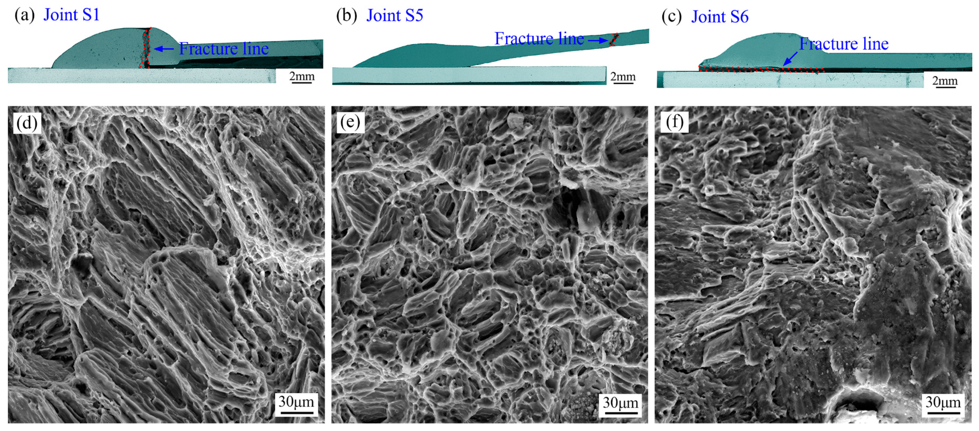
3.3. Weld Strain Strengthening

Chu et al. [34] reported that the relationship between microhardness value (H) and dislocation density (p) conformed to the following formula:
H = H 0 + α G b p 1 / 2
where H0, α, G, and b are constants of the material. Figure 7 and Figure 8 show that lattice distortion and plenty of dislocations occurred in the shot peened Mg/steel weld with the increased Almen intensity, i.e., with the increase in shot peening passes. So, the formula reveals that for the shot peening joints, the increase in shot peening passes will increase the weld dislocation density and eventually lead to the strengthening of microhardness.
The microhardness variation of shot-peening-treated joints along the depth was detected and the related testing locations and results are illustrated in Figure 10. For samples of S6, the maximum hardness of the weld surface was 64 HV, which was almost 1.36 times that of the matrix. With the detection position away from the weld surface, the hardness value presented a trend of continuous decline and finally approached the original hardness of the weld bead. A similar hardness variation pattern was observed for all weldments treated with various shot peening passes. It is apparent that the significant increase in microhardness is mainly attributed to the coactions of nanocrystals and strain strengthening. The variation of microhardness is consistent with the experimental results above. Meanwhile, the hardness evolution also indicated that the depth of the strain hardening layer was approximately 300 μm.
Table 4 presents the evolution of surface properties such as surface roughness, maximum hardness, and maximum residual compressive stress under a series of shot peening intensities. The present results indicate that shot peening intensity has a marked impact on the surface performance of the weld seam. With the increase in MSP strength, the surface layer of the weld underwent more severe plastic deformation, resulting in varying degrees of improvement in maximum hardness value and maximum residual compressive stress, indicating an effective deformation strengthening effect. However, the increasing surface roughness indicates that high shot peening intensity may cause new surface defects and deteriorate weld performance. It is well known that energy is transferred from the projectile to the target material during the MSP treatment process, and the energy possessed by the projectile is a function of projectile density, size, and velocity [14]. Since the shot peening strength is a measure of the induced strain energy, the microprojectiles selected in this study should impact the weld surface at a relatively high speed in order to achieve the target MSP intensity. However, the literature reveals that Mg alloys have limited deformation capacity, and excessive shot velocity can cause a sharp increase in material strain rate and even surface damage, indicating that excessive shot peening strength may lead to a decrease in the mechanical properties of the weld seam.
Figure 11 presents the tensile strength of weldments treated with various shot peening passes. The initial welding strength of the joint without shot peening was 190 MPa, and the fracture location was in the center of the weld bead, as presented in Figure 12a. The tensile strength of S2 slightly increased from 190 MPa to 202 MPa with one pass of the shot peening treatment. As the shot peening intensity continued to increase, the welding strength increased gradually. The maximum welding strength of Joint S5 reached 244 MPa under the optimum shot peening intensity, which was 1.28 times that of the non-shot-peening-treated joint. The improvement of mechanical properties of the weldment is mainly attributed to the combination of surface defect elimination, residual compressive stress, refined crystalline strengthening, and surface strain enhancement. At this time, the corresponding fracture failure position was located in the Mg alloy parent metal accompanied by typical plastic fracture characteristics, as shown in Figure 12b,e. Actually, the shot peening process did not always have a positive effect on the tensile strength of weldment. For Sample S6, excessive shot peening caused severe plastic deformation of the weld and excessive residual stress, which eventually led to a decline in the joint strength. The failure position of the joint was transferred from the weld area to the Mg–steel interface, and plenty of platforms appeared on the fracture surface, as illustrated in Figure 12c,f.
Figure 13 shows the fracture diagram of the Mg–steel joint of S6 (with Almen intensity of 0.25 mm N). As can be seen from Figure 13a, with Almen intensity improved to 0.25 mm N, the fracture was located in the Mg/steel interface area during tensile testing. The BSE image of the initial weld zone (unfractured region) revealed that a wavy reaction layer of 10–15 μm in thickness was formed at the Mg/steel interface, which mainly contained Mg/Zn/Al elements, as shown in Figure 13b. The literature indicated that the reaction layer at the Mg/steel interface was mainly composed of α-Mg and MgZn phases [35]. Due to excessive shot peening treatment, severe plastic deformation was caused in the weld zone and excessive residual stress was introduced, which tended to disrupt the continuity of the intermetallic compound layer in the Mg/steel interface area, ultimately causing the Mg/steel joint to break at the interface area during tensile testing, as shown in Figure 13c.

3.4. Corrosion Characteristics

The stress corrosion sensitivity testing results of Mg/steel joints are presented in Table 5. Table 5 shows that MSP treatment significantly affects the stress corrosion sensitivity of joints. With the increase in MSP intensity (within the range of 0–0.25 mm N), the stress corrosion sensitivity of Mg/steel weld decreases gradually. The stress corrosion sensitivity has a minimum value of 11.2 with MSP intensity of 0.25 mm N. The literature indicates that the stress corrosion sensitivity of welds is influenced by the microstructure evolution [36]. In this study, severe plastic deformation occurred during the MSP process, which induced grain refinement on the weld surface. And the inhibitory effect on the crack initiation and propagation stages is shown in Figure 14. During the crack initiation stage, due to the presence of more grains in the fine-grained area of weld surface to bear the driving force of the crack, stress concentration was reduced and crack initiation was delayed, ultimately reducing the stress corrosion sensitivity index.
Due to the active chemical properties of magnesium alloys, the following chemical reactions occurred even in neutral solutions [37]:
M g + 2 H 2 O = M g O H 2 + H 2
The above reaction equation indicates that a layer of Mg(OH)2 film will rapidly form on the surface of Mg alloy, which was beneficial for protecting the Mg alloy matrix from further damage. Therefore, the performance of Mg(OH)2 passivation film played a decisive role in the corrosion resistance of Mg alloys. In fact, the corrosion process of magnesium alloy was the continuous destruction and repair of Mg(OH)2 passivation film [37]. However, the oxide film on the surface of Mg alloys was prone to groove corrosion damage with the presence of Cl−1 in the environment, as shown in Figure 15a. This is because surface tensile stress also occurs during the formation of the oxide film, which gradually increases and accelerates the corrosion rate of the Mg alloy matrix [38]. During the MSP process of Mg/steel joints, the severe plastic deformation of the weld surface induced grain refinement and residual compressive stress. The transition from tensile stress to compressive stress on the Mg/steel weld surface was beneficial for increasing the density of the passivation film and slowing down its damage, as shown in Figure 15b. At the same time, it also has a positive impact on suppressing crack initiation and propagation, ultimately effectively improving the corrosion resistance of welds.

4. Conclusions

The shot peening treatment of Mg–steel weldment was carried out with Almen intensity ranging from 0.05–0.25 mm N. The weld surface morphology, microstructure features, mechanical properties, and corrosion characteristics of weldment were investigated and discussed. The main conclusions that can be drawn from the present investigation are as follows.
(1)
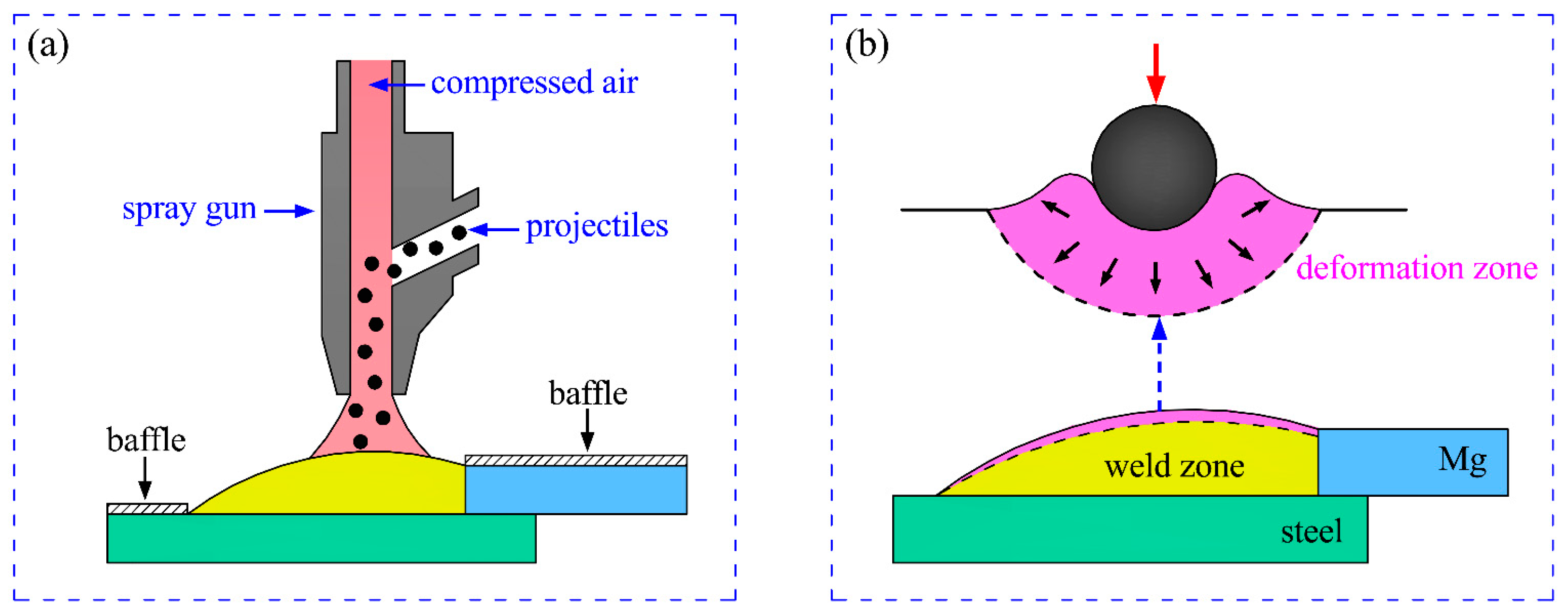
For Mg–steel joints, plastic deformation of the surface layer induced by optimal shot peening intensity of 0.20 mm N was beneficial to eliminate surface microdefects. And the residual tensile stress on the weld surface was transformed into residual compressive stress, which can inhibit the initiation and propagation of microdefects on the weld surface.
(2)
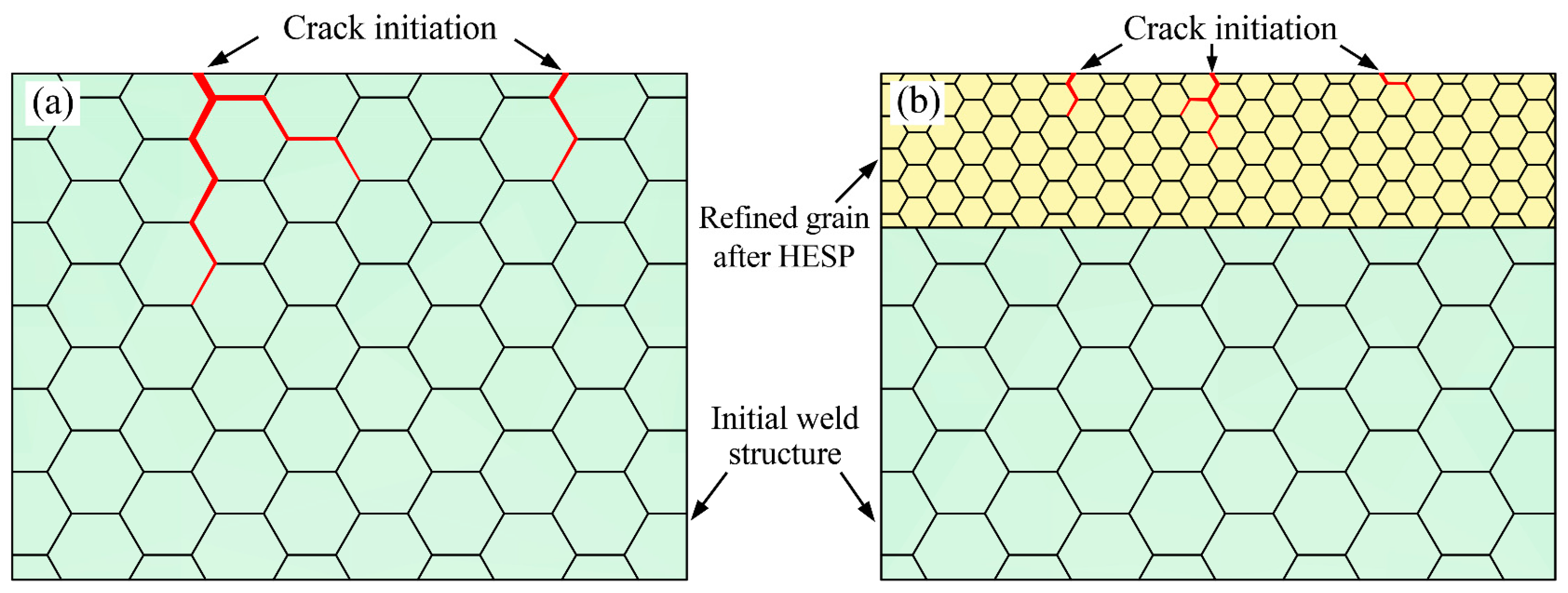
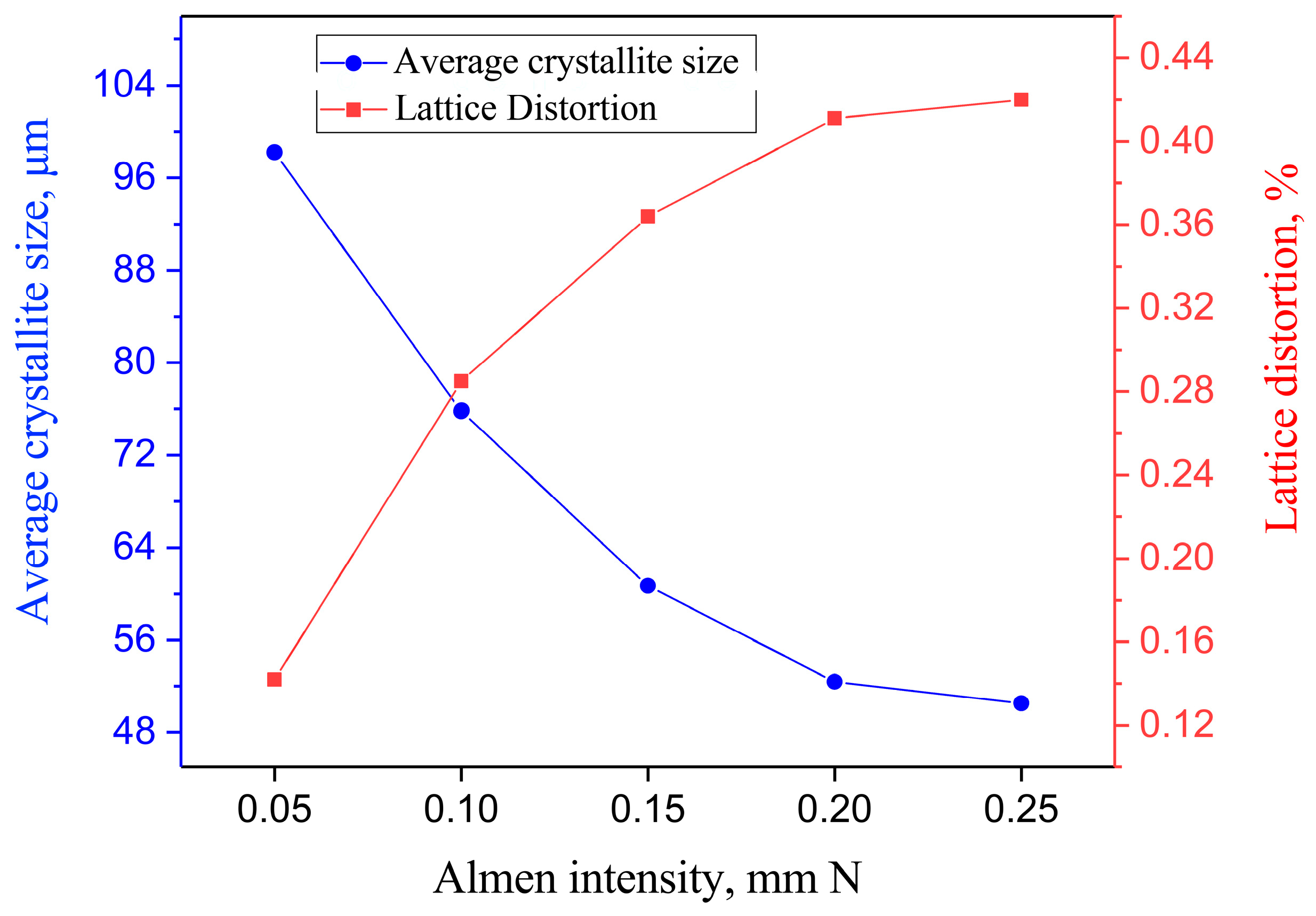
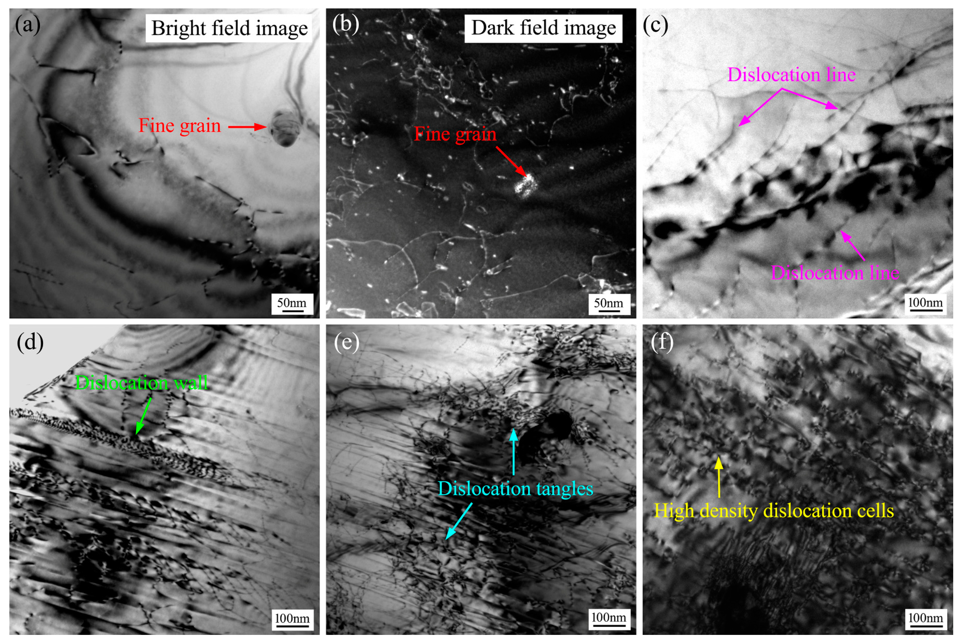
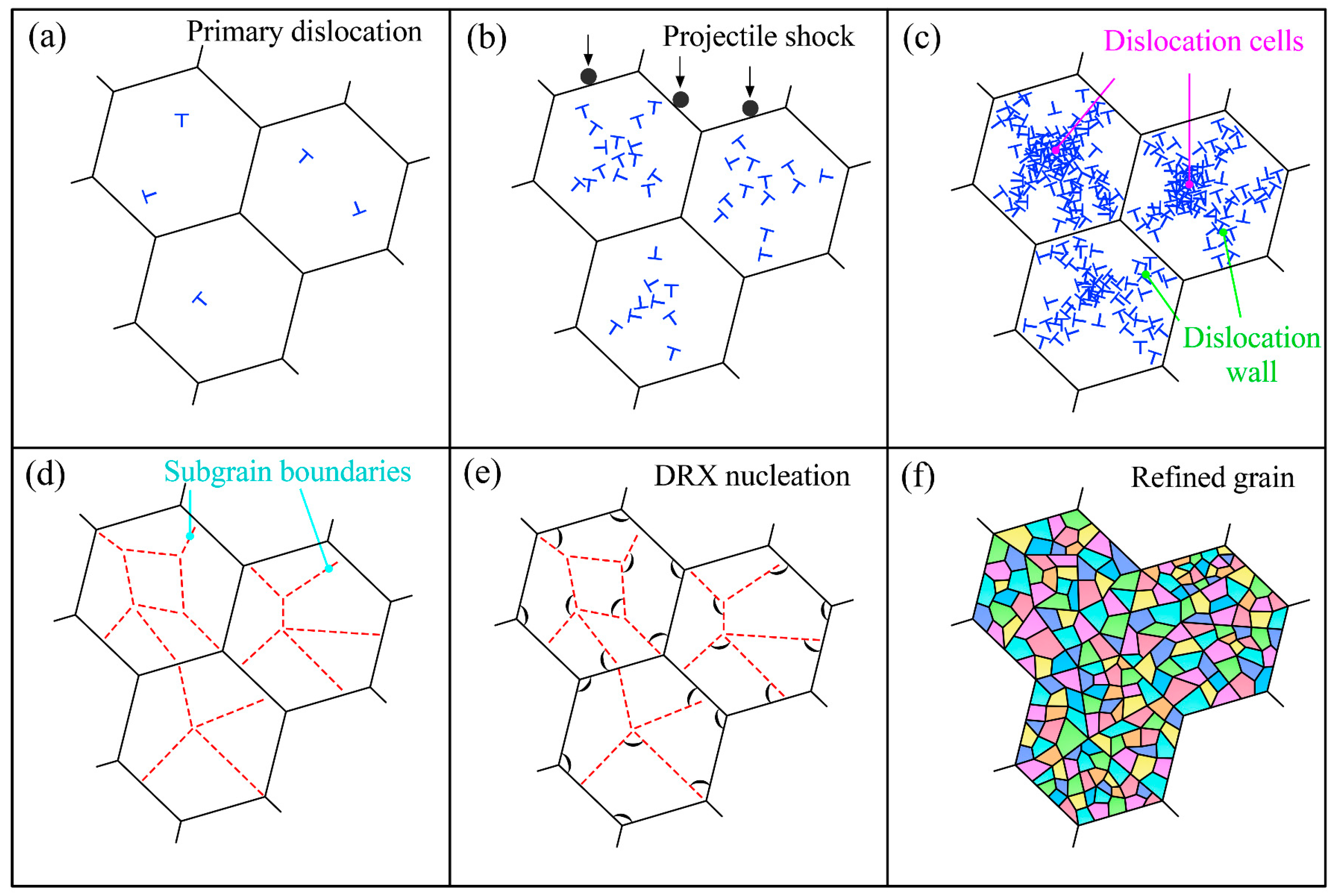
Under the repeated impact of projectiles, the metal on the surface of the welding seam deformed violently, and the refinement strengthening and strain strengthening on the surface of the welding seam were realized.
(3)
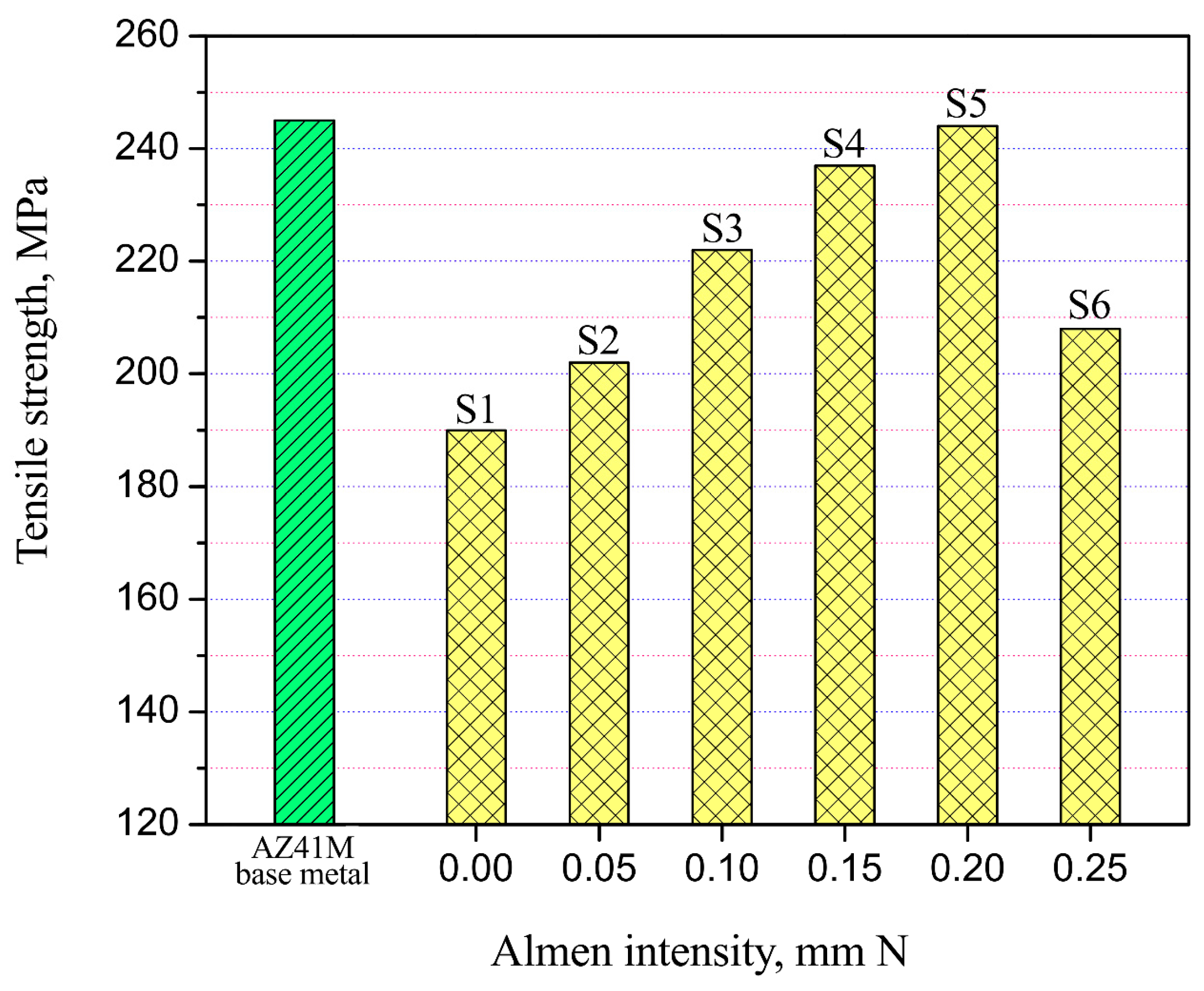
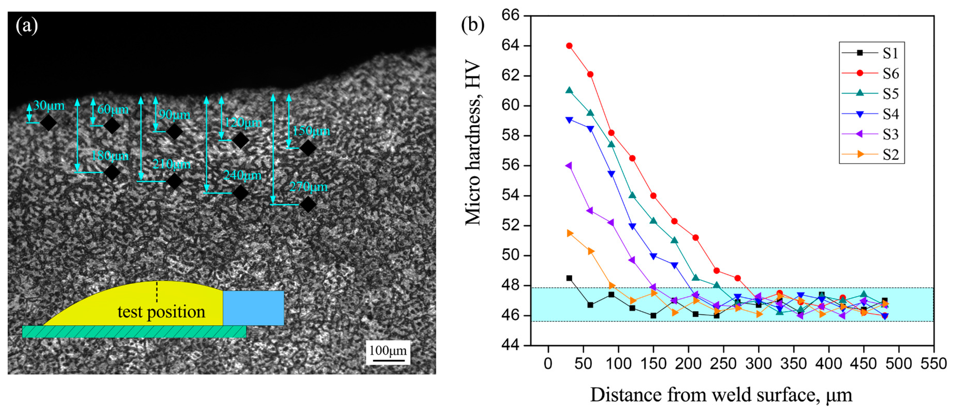
With the increase in depth from the weld surface, the gradient variation of microhardness from 64 HV to 47 HV was obtained, attributed to the combined action of strain strengthening and grain refining. Compared with untreated joints, the tensile strength of Mg–steel specimens with optimal shot peening intensity of 0.20 mm N was notably enhanced and raised by about 28% to 244 MPa.
(4)
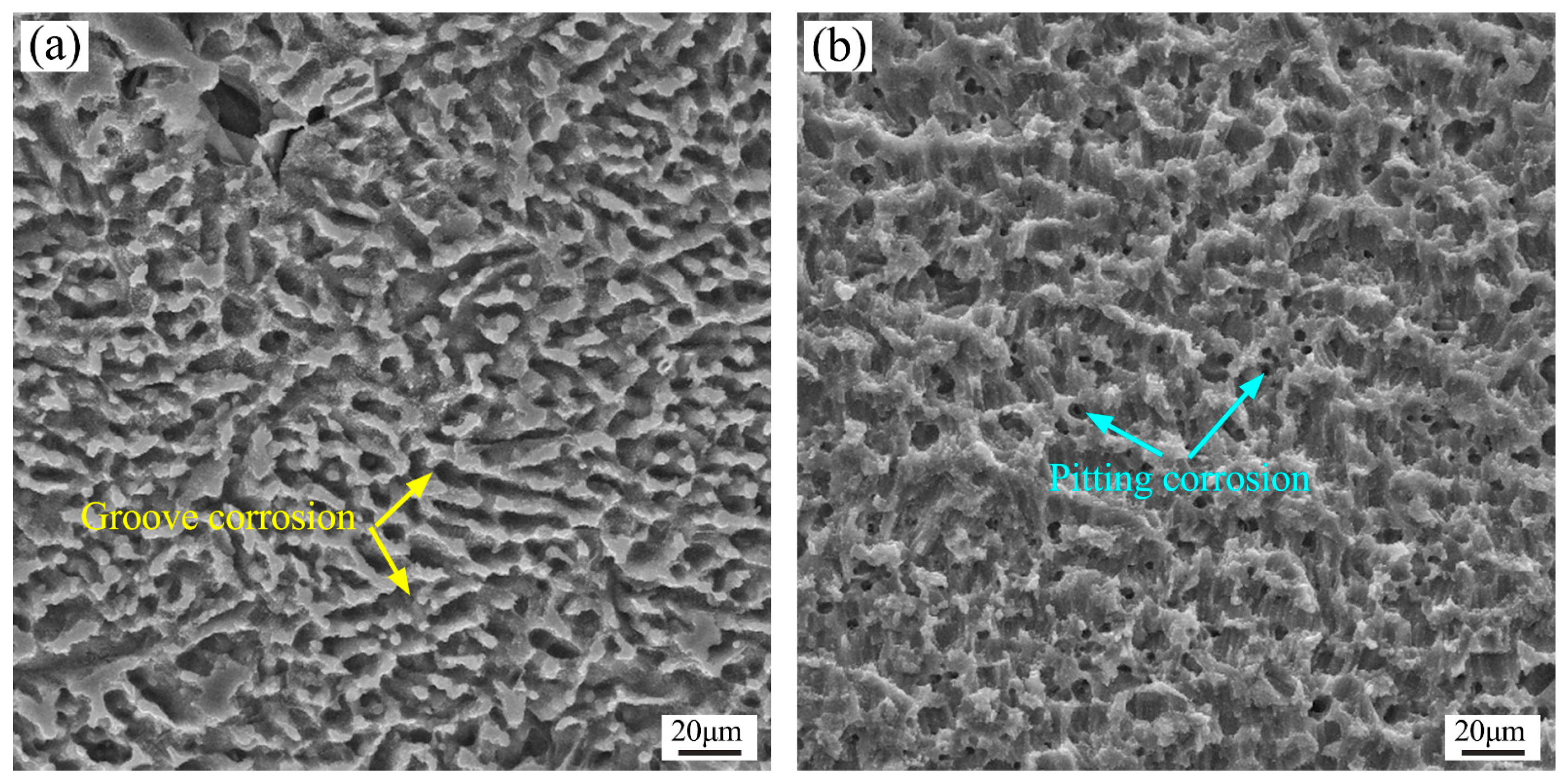
The microstructure evolution induced by MSP treatment was beneficial to improve the stress corrosion sensitivity of Mg/steel joints, while also promoting the formation of a denser Mg(OH)2 passivation film on the weld surface and enhancing the corrosion resistance of the joints.

Author Contributions

Conceptualization, J.W. and C.X.; Writing—review & editing, J.W. and C.X.; Data curation, J.W.; Formal analysis, J.W.; Investigation, J.W.; Validation, J.W.; Writing—original draft, J.W.; Funding acquisition, C.X.; Methodology, C.X.; Resources, C.X. All authors have read and agreed to the published version of the manuscript.

Funding

This research was funded by [Chongqing Municipal Education Commission] grant number [KJQN201901416] and [KJQN202201414], [Yangtze Normal University] grant number [0107/011160023].

Data Availability Statement

All relevant data has been listed in this paper.

Acknowledgments

Thanks to Zhong Zhang, Long Zhang and Xi Wang for the assistance in experimental research.

Conflicts of Interest

The authors declare that they have no conflict of interest.

References

  1. He, C.S.; Li, Y.; Wei, J.X.; Zhang, Z.Q.; Tian, N.; Qin, G.W.; Zhao, X. Enhancing the mechanical performance of Al–Zn–Mg alloy builds fabricated via underwater friction stir additive manufacturing and post-processing aging. J. Mater. Sci. Technol. 2022, 108, 26–36. [Google Scholar] [CrossRef]
  2. Zhang, Z.Q.; He, C.S.; Li, Y.; Yu, L.; Zhao, S.; Zhao, X. Effects of ultrasonic assisted friction stir welding on flow behavior, microstructure and mechanical properties of 7N01-T4 aluminum alloy joints. J. Mater. Sci. Technol. 2020, 43, 1–13. [Google Scholar] [CrossRef]
  3. Zhang, P.; Yue, X.J.; Wang, P.H.; Zhai, Y.C. Influence of SiC pellets water jet peening on the surface integrity of 7075-T6 aluminum alloy. Vacuum 2022, 196, 110760. [Google Scholar] [CrossRef]
  4. Yu, W.H.; Sing, S.L.; Chua, C.K.; Tian, X.L. Influence of re-melting on surface roughness and porosity of AlSi10Mg parts fabricated by selective laser melting. J. Alloys Compd. 2019, 792, 574–581. [Google Scholar] [CrossRef]
  5. Kumar, A.; Sharma, A.; Goel, S.K. Erosion behaviour of WC-10Co-4Cr coating on 23-8-N nitronic steel by HVOF thermal spraying. Surf. Coat. Technol. 2016, 370, 418–426. [Google Scholar] [CrossRef]
  6. Mokabber, T.; Lu, L.Q.; van Rijn, P.; Vakis, A.I.; Pei, Y.T. Crystal growth mechanism of calcium phosphate coatings on titanium by electrochemical deposition. Surf. Coat. Technol. 2018, 334, 526–535. [Google Scholar] [CrossRef]
  7. Miao, X.H.; Chen, R.Z.; Cheng, W.J. Synthesis and characterization of Cu2FeSnS4 thin films prepared by electrochemical deposition. Mater. Lett. 2017, 193, 183–186. [Google Scholar] [CrossRef]
  8. Bokas, G.B.; Zhao, L.; Morgan, D.; Szlufarska, I. Increased stability of CuZrAl metallic glasses prepared by physical vapor deposition. J. Alloys Compd. 2017, 728, 1110–1115. [Google Scholar] [CrossRef]
  9. Song, C.; Liu, M.; Deng, Z.Q.; Niu, S.P.; Deng, C.M.; Liao, H.L. A novel method for in-situ synthesized TiN coatings by plasma spray-physical vapor deposition. Mater. Lett. 2018, 217, 127–130. [Google Scholar] [CrossRef]
  10. Ye, Z.X.; Wang, T.; Wu, S.; Ji, X.H.; Zhang, Q.Y. Na-doped ZnO nanorods fabricated by chemical vapor deposition and their optoelectrical properties. J. Alloys Compd. 2017, 690, 189–194. [Google Scholar] [CrossRef]
  11. Lu, J.Z.; Wu, L.J.; Sun, G.F.; Luo, K.Y.; Zhang, Y.K.; Cai, J.; Cui, C.Y.; Luo, X.M. Microstructural response and grain refinement mechanism of commercially pure titanium subjected to multiple laser shock peening impacts. Acta Mater. 2017, 127, 252–266. [Google Scholar] [CrossRef]
  12. Li, J.; Feng, A.X.; Zhou, J.Z.; Chen, H.; Sun, Y.J.; Tian, X.L.; Huang, Y.; Huang, S. Enhancement of fatigue properties of 2024-T351 aluminum alloy processed by cryogenic laser peening. Vacuum 2019, 164, 41–45. [Google Scholar] [CrossRef]
  13. Liu, P.; Sun, S.Y.; Xu, S.B.; Li, Y.; Ren, G.C. Microstructure and properties in the weld surface of friction stir welded 7050-T7451 aluminium alloys by laser shock peening. Vacuum 2018, 152, 25–29. [Google Scholar] [CrossRef]
  14. Liu, Y.G.; Li, H.M.; Li, M.Q. Roles for shot dimension, air pressure and duration in the fabrication of nanocrystalline surface layer in TC17 alloy via high energy shot peening. J. Manuf. Process 2020, 56, 562–570. [Google Scholar] [CrossRef]
  15. Wang, J.; Lu, Y.L.; Zhou, D.S.; Sun, L.Y.; Xie, L.; Wang, J.T. Mechanical properties and microstructural response of 2A14 aluminum alloy subjected to multiple laser shock peening impacts. Vacuum 2019, 165, 193–198. [Google Scholar] [CrossRef]
  16. Unal, O.; Maleki, E.; Varol, R. Plasma nitriding of gradient structured AISI 304 at low temperature: Shot peening as a catalyst treatment. Vacuum 2019, 164, 194–197. [Google Scholar] [CrossRef]
  17. Chen, M.; Xing, S.L.; Li, J.S.; He, J.S.; Lu, Y.; Jiang, C.H.; Ji, V. Surface residual stress and microstructure evolutions of Hastelloy X alloy after severe shot peening. Vacuum 2021, 187, 110136. [Google Scholar] [CrossRef]
  18. Zhu, L.H.; Guan, Y.J.; Lin, J.; Zhai, J.Q.; Xie, Z.D. The enhanced thermal stability of the nanocrystalline-amorphous composite layer on pure titanium induced by ultrasonic shot peening. J. Alloys Compd. 2019, 791, 1063–1069. [Google Scholar] [CrossRef]
  19. Shen, X.J.; Shukla, P.; Swanson, P.; An, Z.B.; Prabhakaran, S.; Waugh, D.; Nie, X.F.; Mee, C.; Nakhodchi, S.; Lawrence, J. Altering the wetting properties of orthopaedic titanium alloy (Ti–6Al–7Nb) using laser shock peening. J. Alloys Compd. 2019, 801, 327–342. [Google Scholar] [CrossRef]
  20. Li, R.; Yuan, X.J.; Hong, M.; Tao, S.W.; Chen, Z.; Wang, G. Effect of High Energy Shot Peening on the Microstructure and Mechanical Property of AZ31B Mg Alloy/HSLA350 Steel Lap Joints. Int. J. Precis. Eng. Manuf. 2021, 22, 831–841. [Google Scholar] [CrossRef]
  21. Zhang, P.; Lindemann, J.; Leyens, C. Shot peening on the high-strength wrought magnesium alloy AZ80—Effect of peening media. J. Mater. Process. Technol. 2010, 210, 445–450. [Google Scholar] [CrossRef]
  22. Xie, L.C.; Wen, Y.; Zhan, K.; Wang, L.Q.; Jiang, C.H.; Ji, V. Characterization on surface mechanical properties of Ti-6Al-4V after shot peening. J. Alloys Compd. 2016, 666, 65–70. [Google Scholar] [CrossRef]
  23. Kovacı, H.; Bozkurt, Y.B.; Yetim, A.F.; Aslan, M.; Çelik, A. The effect of surface plastic deformation produced by shot peening on corrosion behavior of a low-alloy steel. Surf. Coat. Technol. 2019, 360, 78–86. [Google Scholar] [CrossRef]
  24. Harada, Y.; Fukaura, K.; Haga, S. Influence of microshot peening on surface layer characteristics of structural steel. J. Mater. Process Technol. 2007, 191, 297–301. [Google Scholar] [CrossRef]
  25. Hou, L.F.; Wei, Y.H.; Shu, X.F.; Xu, B.S. Nanocrystalline structure of magnesium alloys subjected to high energy shot peening. J. Alloys Compd. 2010, 492, 347–350. [Google Scholar] [CrossRef]
  26. Dekhtyar, A.I.; Mordyuk, B.N.; Savvakin, D.G.; Bondarchuk, V.I.; Moiseeva, I.V.; Khripta, N.I. Enhanced fatigue behavior of powder metallurgy Ti-6Al-4V alloy by applying ultrasonic impact treatment. Mater. Sci. Eng. A 2015, 641, 348–359. [Google Scholar] [CrossRef]
  27. Zhang, P.; Lindemann, J. Influence of shot peening on high cycle fatigue properties of the high-strength wrought magnesium alloy AZ80. Scripta Mater. 2005, 52, 485–490. [Google Scholar] [CrossRef]
  28. Hilley, M.E.; Larson, J.A.; Jatczak, C.F.; Ricklefs, R.E. Residual Stress Measurement by X-ray Diffraction SAE J784a; Society of Automotive Engineers, Inc.: New York, NY, USA, 1971. [Google Scholar]
  29. Price, J.W.H.; Pardowska, A.M.; Ibrahim, R.; Finlayson, T.R. Residual stresses evaluation in welds and implications for design for pressure vessel applications. J. Press. Vessel. Technol. 2006, 128, 638–643. [Google Scholar] [CrossRef]
  30. Teplov, V.A.; Pilugin, V.P.; Gaviko, V.S.; Chernyshov, E.G. Nanocrystalline structure of non-equilibrium Fe-Cu alloy obtained by severe plastic deformation under pressure. Nanostruct. Mater. 1995, 6, 437–440. [Google Scholar] [CrossRef]
  31. Somekawa, H.; Singh, A.; Mukai, T. High fracture toughness of extruded Mg–Zn–Y alloy by the synergistic effect of grain refinement and dispersion of quasicrystalline phase. Scr. Mater. 2007, 56, 1091–1094. [Google Scholar] [CrossRef]
  32. Mordyuk, B.N.; Iefimov, M.O.; Prokopenko, G.I.; Golub, T.V.; Danylenko, M.I. Structure, microhardness and damping characteristics of Al matrix composite reinforced with AlCuFe or Ti using ultrasonic impact peening. Surf. Coat. Technol. 2010, 204, 1590–1598. [Google Scholar] [CrossRef]
  33. Tian, Y.B.; Shen, J.Q.; Hu, S.S.; Liang, Y.; Bai, P.F. Effects of ultrasonic peening treatment on surface quality of CMT-welds of Al alloys. J. Mater. Process Technol. 2018, 254, 193–200. [Google Scholar] [CrossRef]
  34. Chu, J.P.; Rigsbee, J.M.; Banas, G.; Elsayed-Ali, H.E. Laser-shock processing effects on surface microstructure and mechanical properties of low carbon steel. Mater. Sci. Eng. A 1999, 260, 260–268. [Google Scholar] [CrossRef]
  35. Song, G.; Yu, J.W.; Li, T.T.; Wang, J.F.; Liu, L.M. Effect of laser-GTAW hybrid welding heat input on the performance of Mg/Steel butt joint. J. Manuf. Process. 2018, 31, 131–138. [Google Scholar] [CrossRef]
  36. Lu, Z.M.; Shi, L.M.; Zhu, S.J.; Tang, Z.D.; Jiang, Y.Z. Effect of high energy shot peening pressure on the stress corrosion cracking of the weld joint of 304 austenitic stainless steel. Mater. Sci. Eng. A 2015, 637, 170–174. [Google Scholar]
  37. Gao, W.; Wang, S.R.; Wang, G.Q.; Zhou, J.X. Effect of high energy shot peening on electrochemical corrosion resistance of WE43 magnesium alloy. Int. Conf. Eng. Manag. 2016, 30, 227–232. [Google Scholar]
  38. Wang, F.H.; Du, K.Q.; Zhang, W. Progress in research of Corrosion and protection of magnesium alloys. Mater. China 2011, 30, 29–34. [Google Scholar]
Figure 1. The schematic illustration of shot peening process (a) and strengthening mechanism (b).
Metals 14 00470 g001
Figure 2. Sampling position of Mg–steel joint: Ⅰ tensile test specimen, Ⅱ specimen for microhardness and microstructure analysis.
Metals 14 00470 g002
Figure 3. Typical surface microstructure of Mg–steel specimen: (a,c,d) without shot peening (Joint S1); (b,e) with shot peening process (Joint S5).
Metals 14 00470 g003
Figure 4. Surface roughness measurement results of weld and base metal after MSP treatment: (a) maximum profile height Ry, (b) arithmetic average roughness Ra.
Metals 14 00470 g004
Figure 5. Depth distribution of residual stress on Mg–steel weld after varied shot peening passes.
Metals 14 00470 g005
Figure 6. The typical metallographic diagram of (a) base material, (b) cross-section of traditional Mg–steel weld (Joint S1), and (c) cross-section of shot peened Mg–steel weld (Joint S5).
Metals 14 00470 g006
Figure 7. Calculation results of average crystallite dimension and lattice distortion of weld surface after microshot peening treatment.
Metals 14 00470 g007
Figure 8. TEM field images of weld surface zone: (a) and (b) Joint S5, (c) Joint S2, (d) Joint S3, (e) Joint S4, and (f) Joint S6.
Metals 14 00470 g008
Figure 9. The grain refining process of Mg–steel weld under multiple shot peening: (a) low-density dislocations in original grains, (b) dislocation multiplies under projectile impact, (c) dislocation walls and dislocation cells, (d) subgrain boundaries, (e) dynamic recrystallization nucleation, and (f) refined grain.
Metals 14 00470 g009
Figure 10. Schematic diagram of hardness measurement position (a) and the microhardness variations of weld surface zone with varied peening parameters (b).
Metals 14 00470 g010
Figure 11. Tensile strength of Mg–steel weldment under MSP treatment.
Metals 14 00470 g011
Figure 12. Typical fracture features of Mg–steel joint under shot peening treatment: (ac) fracture locations of Joints S1, S5, and S6, (df) fracture appearances of Joints S1, S5, and S6.
Metals 14 00470 g012
Figure 13. Fracture diagram of Mg–steel joint of S6 (with Almen intensity of 0.25 mm N): (a) fracture process, (b,c) enlarged view of initial weld area and fractured weld zone, respectively.
Metals 14 00470 g013
Figure 14. Schematic diagram of the influence of grain refinement on the evolution of stress corrosion cracks: (a) untreated joint, (b) Joint S5 (with MSP strength of 0.20 mm N).
Metals 14 00470 g014
Figure 15. Corrosion morphologies of Mg/steel weldments after 30 min salt bath test (3.5 wt.% NaCl solution): (a) Joint S1 (without MSP), (b) Joint S5 (MSP intensity of 0.20 mm N).
Metals 14 00470 g015
Table 1. The main shot peening treatment parameters.
ParametersValue
Exit diameter of spray gun (mm)4
Projectile diameter (mm)0.8
Accelerating gas pressure (MPa)0.15
Almen intensity (mm N)0.05–0.25
Bombarding distance (mm)15
Table 2. Contrast experiment design with different shot peening passes.
JointS1S2S3S4S5S6
Shot peening pass012345
Almen intensity (mm N)00.050.100.150.200.25
Table 3. The thickness of SDL and TL under different shot peening intensities.
JointS1S2S3S4S5S6
Thickness of SDL (μm)263037445053
Thickness of TL (μm)84101130155176192
Table 4. Properties of weld surface treated with various shot peening strengths.
JointAlmen Intensity
(mm N)
Surface Roughness Ry (μm)Maximum Hardness Value (HV)Maximum Residual Compressive Stress (MPa)
S106.048.4−28
S20.058.551.533
S30.1011.756.156
S40.1513.559.277
S50.2016.260.990
S60.2517.864.097
Table 5. Testing results of stress corrosion sensitivity index for Mg/steel joints.
JointAlmen Intensity (mm N)Corroding SolutionStress Corrosion Sensitivity Index
S10NaCl (3.5%)29.5
S20.05NaCl (3.5%)23.7
S30.10NaCl (3.5%)18.9
S40.15NaCl (3.5%)15.0
S50.20NaCl (3.5%)12.8
S60.25NaCl (3.5%)11.2
Disclaimer/Publisher’s Note: The statements, opinions and data contained in all publications are solely those of the individual author(s) and contributor(s) and not of MDPI and/or the editor(s). MDPI and/or the editor(s) disclaim responsibility for any injury to people or property resulting from any ideas, methods, instructions or products referred to in the content.

