Article

Twinning–Detwinning-Dominated Cyclic Deformation Behavior of a High-Strength Mg-Al-Sn-Zn Alloy during Loading Reversals: Experiment and Modeling

1
School of Mechanical and Automotive Engineering, Qingdao University of Technology, Qingdao 266520, China
2
College of Pipeline and Civil Engineering, China University of Petroleum (East China), Qingdao 266580, China
3
College of New Energy, China University of Petroleum (East China), Qingdao 266580, China
*
Author to whom correspondence should be addressed.
Metals 2024, 14(6), 635; https://doi.org/10.3390/met14060635
Submission received: 26 April 2024 / Revised: 19 May 2024 / Accepted: 24 May 2024 / Published: 27 May 2024
(This article belongs to the Section Structural Integrity of Metals)

Abstract

:
The deformation behavior of a high-strength Mg-Al-Sn-Zn alloy under loading reversals has been thoroughly examined through a combination of experimental measurements and crystal plasticity modeling. We focused on an age-treated alloy fortified by distributed Mg2Sn particles and Mg17Al12 precipitates, which underwent two distinct loading cycles: tension-compression-tension (TCT) and compression-tension-compression (CTC), aligned with the extrusion direction (ED). The initial and deformed microstructures of the alloy were analyzed using the electron backscattering diffraction (EBSD) technique. Notably, the alloy displays tensile and compressive yield strengths (YS) of 215 MPa and 160 MPa, respectively, with pronounced anelastic behavior observed during unloading and reverse loading phases. Utilizing the elasto-viscoplastic self-consistent model incorporating a twinning–detwinning scheme (EVPSC-TDT), the cyclic stress–strain responses and resultant textures of the alloy were accurately captured. The predicted alternation between various slip and twinning modes during plastic deformation was used to interpret the observed behaviors. It was found that prismatic <a> slip plays an important role during the plastic deformation of the studied alloy, and its relative activity in tensile loading processes accounts for up to ~66% and ~67% in the TCT and CTC cases, respectively. Moreover, it was discerned that detwinning and twinning behaviors are predominantly governed by stresses within the parent grain, and they can concurrently manifest during the reverse tensile loading phase in the TCT case. After cyclic deformation, the area fractions of residual twins were determined to be 7.51% and 0.93% in the TCT and CTC cases, respectively, which is a result of the varied twinning–detwinning behavior of the alloy in different loading paths.

1. Introduction

Magnesium (Mg) alloys, renowned as the lightest structural metals boasting low density and high specific strength, have garnered significant interest in the transportation sector. However, their widespread adoption has been hindered by inherent challenges such as poor ductility at ambient temperature and relatively lower strength compared to aluminum alloys and steels. Enhancing the ductility and mechanical strength of Mg alloys necessitates the meticulous optimization of their microstructures. This optimization involves tailoring parameters such as morphology, grain size, precipitates, and crystallographic textures through strategic alloying element additions and the advancement of processing technologies [1,2].
Over the past decades, significant strides have been made in the development of high-strength Mg alloys. This progress has been achieved primarily through the introduction of precipitates and second-phase particles within magnesium-aluminum (Mg-Al), magnesium-zinc (Mg-Zn), and magnesium-rare earth (Mg-RE) systems [2,3]. For instance, Homma et al. [4] developed an Mg-1.8Gd-1.8Y-0.7Zn-0.2Zr alloy, featuring an ultimate tensile strength of 542 MPa, proof stress of 473 MPa, and elongation to failure of 8.0%, by hot extrusion and aging treatment that lead to fine precipitates and dynamic precipitation at the grain boundaries. On the other hand, the improvement of ductility is mainly achieved by refining grain sizes, weakening textures, and reducing the strength ratios between soft and hard deformation modes in both RE-containing and RE-free Mg alloys [5,6,7]. R.K. Sabat [8] reported that an Mg-0.2%Ce alloy fabricated by the equal channel angular pressing process yielded an exceptional uniform elongation of 40%; however, it had a low YS of 55 MPa. Zhang et al. [9] observed that the dynamic precipitation could increase defect density and a supersaturated Zn in the Mg matrix in a ZK60 (Mg-6.0Zn-0.5Zr) alloy during low-temperature extrusion, which can promote the nucleation and potential for precipitation during the extrusion process and lead to grain refinement and weakened texture, yielding a relatively high tensile YS of 295 MPa and a remarkably high tensile elongation of 27.7% in the alloy.
Recently, researchers found that the addition of Sn to Mg alloys demonstrated remarkable effectiveness in simultaneously improving the mechanical strength and ductility in both cast [10] and wrought Mg alloys [11,12]. The improved mechanical strength was attributed to fine-grain strengthening, high-density residual dislocations, the presence of numerous hybrid particles such as bimodal Mg17Al12 precipitates and submicron Mg2Sn precipitates, as well as a large number of subgrains. It was also found that the ultimate tensile strength improves with Sn addition of up to 4 wt.% but deteriorates beyond that point due to premature fracture caused by crack initiation at large particles [13]. Wang et al. [14] found that the solid solution Zn and the increased amount of well-dispersed fine Mg2Sn and Mg17Al12 particles were also responsible for the strong work hardening ability, which led to a superior combination of a high tensile strength of 357 MPa and an excellent elongation of 19% in an extruded Mg-8Al-2Sn-1Zn alloy.
It is well known that pre-deformation can have a pronounced influence on the subsequent deformation responses [15], forming limit [16] and fatigue life in Mg alloys [17]. Therefore, the cyclic deformation behavior of Mg alloys has been extensively studied using both experimental (e.g., acoustic emission, neutron and X-ray diffraction, and EBSD) [18,19,20,21] and modeling methods [22,23,24,25], which emphasized the significant role that twinning–detwinning behavior played during loading-unloading and reverse loading cycles. These studies have also demonstrated that the reversal movement of basal <a> slip and detwinning of twinned grains are responsible for the anelastic deformation behavior and the asymmetric hysteresis of Mg alloys during cyclic loadings [26].
While some studies have investigated the alloying effects on the mechanical properties of newly developed Mg-Al-Sn-Zn alloys, most have focused solely on their deformation behaviors under monotonic loadings, and little attention has been directed towards understanding their deformation mechanisms during loading path changes. Hence, the primary objective of this study is to elucidate the deformation mechanisms of Mg-Al-Sn-Zn alloys during loading, unloading, and reverse loadings by combining experimental measurements and crystal plasticity modeling. An Mg-6Al-4Sn-2Zn Mg alloy with minor Nd (0.5 wt.%) and Ce (0.5 wt.%) additions, which are added to potentially improve ductility by weakening the texture and reducing the strength discrepancies between soft deformation modes and hard deformation modes [8,27], was fabricated via an extrusion process followed by aging treatments. Subsequently, the alloy underwent TCT and CTC loading cycles to characterize its deformation behaviors. Analysis of the combined experimental and modeling results enabled the elucidation of the evolution of deformation mechanisms. This included understanding the alternative dominations of various slip and twinning modes, twinning–detwinning behavior, and the evolution of crystallographic textures.

2. Materials and Methods

The nominal chemical compositions of the studied Mg-Al-Sn-Zn alloy are given in Table 1. To fabricate the alloy, pure Mg (99.8 wt.%), Al (99.9 wt.%), Sn (99.97 wt.%), Zn (99.97 wt.%), Mg-Ce (20 wt.%) and Mg-Nd (20 wt.%) were added into a stainless steel crucible, which was preheated to 750 °C under a mixed CO2 (99 vol.%) and SF6 (1 vol.%) atmosphere [28]. An ingot with a diameter of 95 mm and a height of 400 mm was cast by a semi-continuous casting process. It was then subjected to a homogenization treatment at 400 °C for 24 h in a furnace followed by water quenching. The ingot was then extruded at 300 °C with an extrusion ratio of 26 at a speed of 5 mm/s and then cooled to room temperature [28]. The average diameter of the extruded bar was 18.6 mm. After that, aging treatments of the extruded alloy were performed at 150 °C [28]. An energy-dispersive X-ray spectrometry (EDS) measurement was performed to determine the chemical compositions of the alloy on the cross-sectional plane of the extruded bar, and the obtained results are presented in Table 1 and Figure 1a–h. Region 1 was close to the center of the cross-section, and Region 2 was close to the mid-distance site between the edge and the center of the cross-section along the radial direction. It can be seen in Figure 1c,g that the distribution of Sn is obviously non-uniform with concentrations in some locations. A lower level concentration of Al can be also identified in Figure 1b,f. The distribution of Zn is almost uniform in Figure 1d,h. These varied compositional distributions are closely related to the distribution of phase constituents of the alloy. To analyze the phase constituents, X-ray diffraction (XRD) was performed using an X-ray diffractometer (Rigaku Smartlab SE, Tokyo, Japan) on the plane perpendicular to the ED of the alloy. Figure 1i shows the obtained XRD pattern, which indicates the formation of Mg2Sn, MgZn2, and Mg17Al12 precipitates embedded in the Mg matrix. Based on the above results, it can be concluded that the distributions of MgZn2 and Mg17Al12 are generally uniform and that of Mg2Sn is non-uniform, which is consistent with the results reported in [11,29].
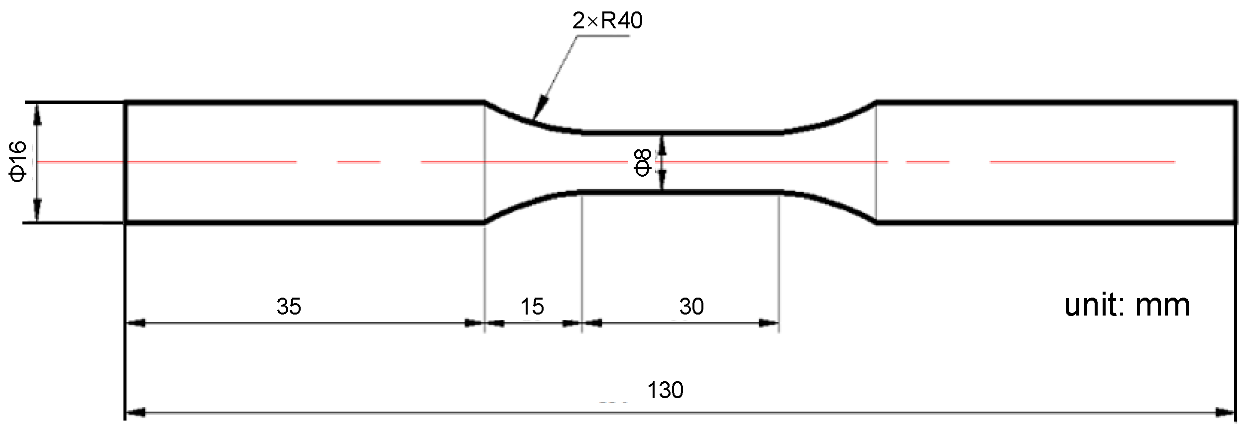
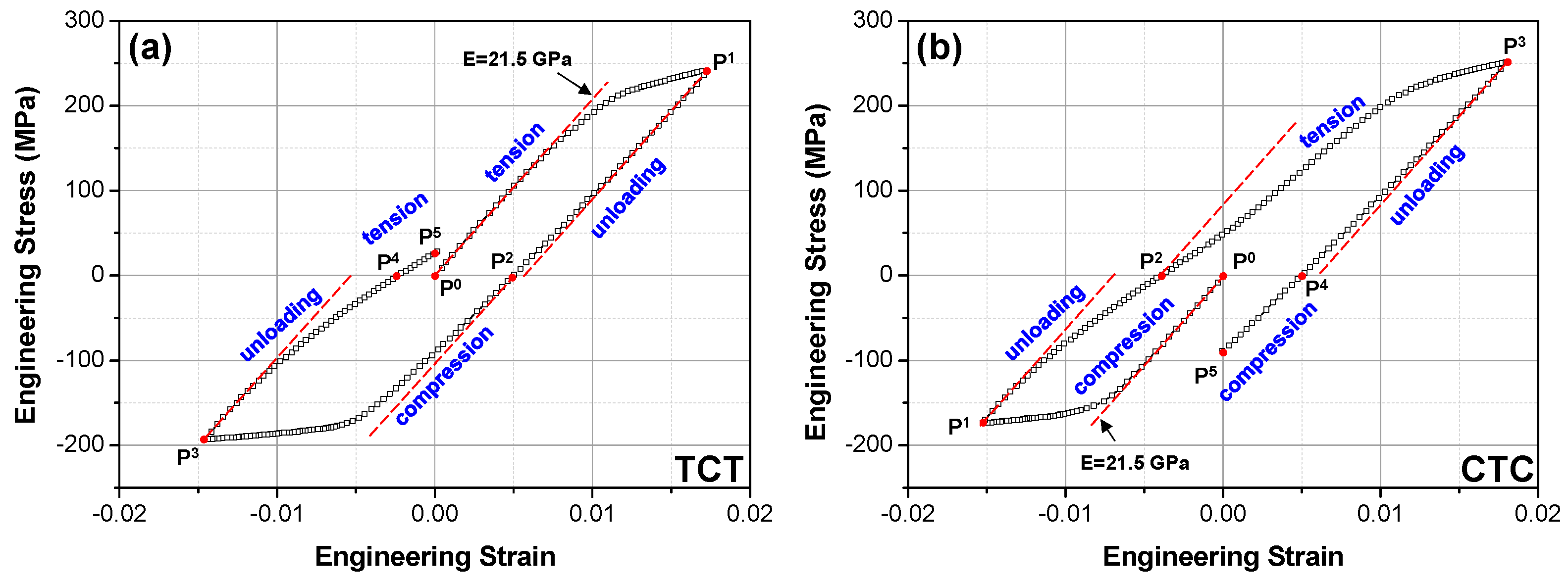
As depicted in Figure 2, round dog-bone-shaped specimens, longitudinally parallel to the ED, were cut along the ED of the extruded bar using electrical discharge machining (EDM). The axis of the specimen is aligned with the extrusion axis of the alloy. According to the ASTM standard E606/E606M-21 [30], two specimens were subjected to the TCT and CTC loading cycles in strain-control mode, as illustrated in Figure 3, on an MTS universal mechanical tensile tester, and their cyclic deformation behaviors were recorded during each measurement. For each case, the loading cycle consisted of five loading/unloading processes, involving two loading reversals, and the final strain of each specimen was prescribed to be zero. The loading sequence was tension-unloading-compression-unloading-tension in the TCT case, and it was compression-unloading-tension-unloading-compression in the CTC case. In both tests, the nominal strain rate was prescribed to be 0.001 s−1.
The microstructures and crystallographic textures of the alloy before and after cyclic loadings were measured using the EBSD method. For both undeformed and deformed samples, the EBSD samples were extracted from the center of them along the longitudinal direction. The samples were polished using SiC papers and then electrolytically polished in an ACII polishing solution with a voltage of 25 V and a current of 0.11 A, respectively [28]. The sample scanning was performed on the plane perpendicular to the ED of the alloy with a step size of 0.8 μm in an EBSD system inside a field emission scanning electron microscope (FE-SEM, Hitachi SU-3800, Tokyo, Japan). The obtained raw EBSD data were treated using a clean-up step, consisting of grain confidence index standardization and grain dilation, with a grain misorientation of 5° and a minimum equivalent grain size of 4 pixels. Then, the cleaned EBSD data were analyzed using EDAX TSL OIM Analysis ver.7.2.

3. Crystal Plasticity Modeling

3.1. The EVPSC-TDT Model

In this section, the EVPSC-TDT model developed in [31] is briefly described. The EVPSC model treats each grain, with a discrete weighted volume fraction, as an EVP inclusion embedded in and interacting with the EVP homogeneous effective medium (HEM) that represents the polycrystalline aggregate. A mean-field homogenization approach was adopted to simulate the EVP responses of a polycrystal and self-consistently determines the mechanical responses of both the aggregate and its constitutive grains. For a single grain, its total strain rate is decomposed into the elastic and viscoplastic parts. The elastic part is related to the stress rate of the grain through the single crystal constitutive law [31]:
σ   * + σ t r d e = C d e
where C is the fourth-order elastic stiffness tensor, d e is the elastic strain rate tensor, and σ   * is the Jaumann rate of the Cauchy stress σ based on the lattice spin tensor ω e .
The viscoplastic part is due to the shear rates resulting from the operative slip and twinning modes during deformation [31]:
d v p = α γ ˙ α 1 2 s α n α + n α s α
where d v p is the viscoplastic strain rate tensor, α represents a slip/twinning system, γ ˙ α is the shear rate of α , s α is the slip or twinning direction and n α is the direction normal to the slip/twinning plane. For a slip/twinning system, the driving force for the shear rate is the resolved shear stress τ α = σ P α = s α · σ · n α .
The shear rate for slip system α is determined by [31]:
γ ˙ α = γ ˙ 0 τ α / τ c r α 1 / m s g n τ α
where γ ˙ 0 is a reference shear rate, τ c r α is the critical resolved shear stress (CRSS,), and m is the strain rate sensitivity factor. For twinning (and detwinning), due to the polar nature, Equation (3) is valid only when it is in the positive direction; otherwise, the shear rate is zero.
In the TDT scheme, a newly nucleated twin is treated as a new grain apart from the parent grain. Both of them are embedded in and interacting with the aggregate, and the parent grain is split into an untwinned domain (matrix) and a twinned domain (twin). However, their summed volume fraction remains unchanged. Once a twin variant is nucleated inside a grain, the new grain is assigned an initial orientation determined by the rotation matrix Q = 2 n α n α −1 of the relevant twin orientation. The twinning process (twin growth) mechanism is achieved by two operations, i.e., matrix reduction (MR) and twin propagation (TP), and the detwinning process is achieved by two other operations, i.e., twin reduction (TR) and matrix propagation (MP). Due to the different stress states in the matrix and the twin, the stress of the matrix is allowed to trigger MP and MR, while TR and TP can be triggered by the stress of the twin. For MR and TR, the corresponding changes in the twin volume fractions are calculated by [31]:
f ˙ M R α = γ ˙ M R α / γ t w     a n d   f ˙ T R α = γ ˙ T R α / γ t w
For MP and TP, the corresponding changes in the twin volume fractions are calculated by [31]:
f ˙ T P α = γ ˙ T P α / γ t w   and   f ˙ M P α = γ ˙ M P α / γ t w
where γ t w is the characteristic twinning shear strain and is 0.129 for tension twinning in Mg alloys [32]. Through these four operations, the total change of the twin volume fraction can be calculated with respect to the matrix grain as [31]:
f ˙ α = f M f ˙ M R α + f ˙ M P α + f α f ˙ T P α + f ˙ T R α
where f M = 1 f t w = 1 α f α is the volume fraction of the matrix.
Because a grain can rarely be fully twinned, a threshold twin volume fraction is defined to terminate twinning. Following the method described in [33], we introduce two statistical variables: accumulated twin fraction V a c c and effective twinned fraction V e f f . More specifically, V a c c and V e f f are the weighted volume fractions of the twinned region and the volume fraction of twin terminated grains, respectively. The threshold volume fraction V t h is then defined as [33]:
V t h = m i n 1.0   , A + B V e f f / V a c c
where A and B are two material constants.
For both slip and twinning, the evolution of the critical resolved shear stress (CRSS), τ c r α , is defined by [33]:
τ ˙ c r α = d τ ^ α d Γ β h α β γ ˙ β
where Γ = α γ α is the accumulated shear strain in a grain, and h α β is the latent hardening coefficient, which empirically accounts for the obstacles on system α associated with system β. τ ^ α is the threshold stress, which is updated by [33]:
τ ^ α = τ 0 α + τ 1 α + θ 1 α γ α 1 e x p θ 0 α τ 1 α
where τ 0 α , θ 0 α , θ 1 α , and τ 0 α + τ 1 α are the initial CRSS, the initial hardening rate, the asymptotic hardening rate, and the back-extrapolated CRSS, respectively, associated with the slip/twinning system α.
The above equations are the basic constitutive laws for a single crystal, and the self-consistent approach used in the model is briefly mentioned as follows. The deformation rate tensor d of a grain can be decomposed into elastic and viscoplastic parts. The elastic part d e is linked with the Cauchy stress rate σ ˙ via the elastic compliance tensor M e and the viscoplastic d v p is linked with the Cauchy stress itself σ via a linearized viscoplastic compliance tensor M v p . Following [31], the total deformation rate of the grain is expressed by
d = d e + d v p = M e : σ ˙ + M v p : σ + d 0
where d 0 is a back-extrapolated term solved during self-consistent iterations.
The self-consistent approach [31] assumes that the EVP behavior of the HEM has a linear relation analogical to that of a single crystal (Equation (12)), that is,
D = M ¯ e : Σ ˙ + M ¯ v p : Σ + D 0
where D , M ¯ e , M ¯ v p , Σ , and D 0 are, respectively, the strain rate, the elastic compliance, the viscoplastic compliance, the Cauchy stress, and the back-extrapolated term for the HEM.
The strain rate and stress of each grain are self-consistently related to the corresponding values of the HEM by the following interaction equation [31]:
d D = M ~ e σ ˙ Σ ˙ M ~ v p σ Σ
where the elastic and viscoplastic interaction tensors M ~ e and M ~ v p are given by [31]:
M ~ e = I S e 1 : S e : M ¯ e
M ~ v p = I S v p 1 : S v p : M ¯ v p
Here, S e and S v p are the elastic and viscoplastic Eshelby tensors, respectively, for a given grain, and I is the identity tensor [31]. Different linearizations of the single crystal behavior lead to different self-consistent schemes, among which, the affine self-consistent scheme has been shown to provide the best overall performance [34], which is employed in the present study.

3.2. Modeling Details and Parameter Calibration

In the crystal plasticity analyses, the initial texture of the alloy, represented by the orientation distribution function (ODF) that was determined by the EBSD measurement, was discretized into 6000 orientations (each with a weighted volume fraction) using the MTEX packages to represent the constituent grains in the polycrystalline aggregate. The room temperature single crystal elastic constants are taken from [35]: C11 = 58, C12 = 25, C13 = 20.8, C33 = 61.2 and C44 = 16.6 (units of GPa). Due to the relatively lower elastic stiffness of the studied alloy, with a macroscopic Young’s modulus of ~22 GPa (determined from the stress–strain curves in Figure 3), the single crystal elastic constants were multiplied by the ratio between the Young’s modulus of the studied alloy and those of other alloys in previous studies [22,35]. Plastic deformation of the alloy was assumed to occur by basal <a> slip, prismatic <a> slip, pyramidal <c+a> slip, and tension twinning. The reference slip/twinning rate γ ˙ 0 was set to be 0.001 s−1, the rate sensitivity m was set to be 0.05, and h α β was prescribed to be 1.0 and kept the same for all slip/twinning systems [35]. Following the method in [24,36], the CRSSs for TP, MP and TR were assumed to be smaller than that of MR, which is defined by:
τ c r α , M P = τ c r α , T P = τ c r α , T R = κ · τ c r α , M R
where κ is an empirical parameter. The hardening parameters for different slip/twinning modes were calibrated by fitting the stress–strain curves obtained in the cyclic tests (Figure 3). The calibrated parameters are presented in Table 2.

4. Results and Discussion

4.1. Initial Microstructure and Crystallographic Texture

Figure 4 shows the as-aged microstructure and initial crystallographic texture of the studied alloy. It exhibits an equi-axis grain morphology with an average grain size of 19.8 ± 7.0 µm, and no visible twins can be identified on the inverse pole figure (IPF) map (Figure 4a). The crystallographic texture is represented by the (0002) and (10 1 ¯ 0) pole figures in Figure 4b. The IPF color map and the pole figures suggest that the as-aged alloy has a typical basal texture with a maximum pole intensity of 2.688, much lower than that in commercial wrought Mg alloys [17,37]. The grain boundary map in Figure 4c shows that the fraction of high-angle grain boundaries are (HAGBs, with a misorientation angle larger than 15°) is 71%, and twin boundary is hardly seen. The average kernel average misorientation (KAM) is 0.8°, indicating that the alloy is almost fully recrystallized with a low dislocation density.

4.2. Stress–Strain Behavior and Deformed Microstructures

The engineering stress–strain curves of the studied alloy during the TCT and CTC loading cycles are presented in Figure 3. The 0.2% YS of the alloy is determined to be 215 MPa in tension and 160 MPa in compression from the stress–strain curves of the first loading processes (P0~P1) in the TCT and CTC cases, respectively. The high strength of the alloy and the low tension/compression YS ratio (1.3) are attributed to the formation of Mg2Sn and Mg17Al12, resulting in the hardening of tension twinning and the increased activation of non-basal slips, as suggested in previous studies [29,38]. During the unloading processes (P1~P2 and P3~P4), obvious anelastic behavior can be recognized in both loading cases. To better analyze the anelastic behavior, the initial elastic deformation response is highlighted in Figure 3 using a red dashed line starting from P0. It is found that there is no obvious elastic anisotropy during the first loading process of the two cases since the elastic stress–strain behavior with an identical Young’s modulus matches well with the elastic ranges of both curves. The elastic unloading curves at P1 and P3 points and that during reverse loadings at P2 are also highlighted using dashed red lines, which demonstrates that the extent of anelasticity in the tensile unloading process is lower than that in the compressive unloading process. During tensile unloading, the anelastic behavior is mainly due to the reversal movement of basal <a> dislocations [39], while, during compressive unloading, it is driven by the reversal movement of basal <a> dislocations and the detwinning behavior of twinned grains driven by a back stress [25,40]. At the starting stage of the reverse loading process (P2), no clear elastic deformation behavior can be identified, which is also closely related to the detwinning behavior. The detailed deformation mechanisms of the alloy in both the TCT and CTC cases will be analyzed in Section 4.3.
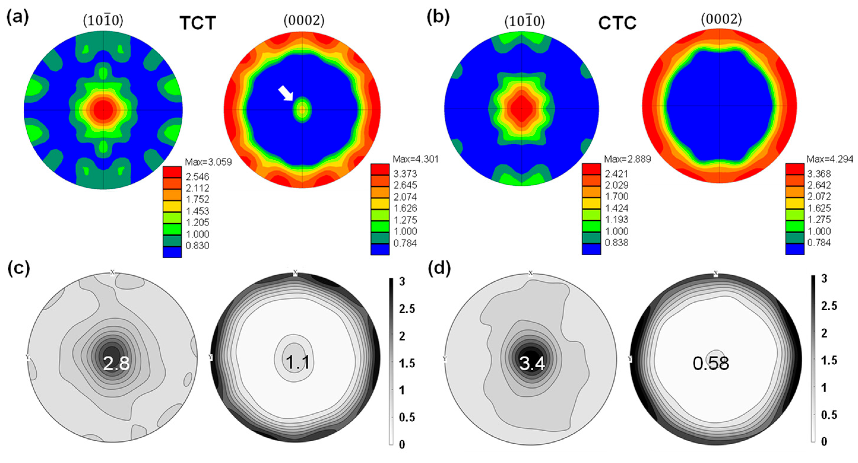
Figure 5 presents the IPF and GB maps of the two deformed specimens. Compared to the initial microstructure in Figure 4a, a clear IPF color change can be recognized for the TCT case. Specifically, many grains have experienced large-angle re-orientation (86.3°) due to twinning activity, as highlighted using red lines in Figure 5b. The number fraction of grains containing residual twins is ~29% in this case. In contrast, the IPF color of the CTC specimen is generally similar to that of the undeformed state. It can be concluded that fewer residual twins remain in this case after the CTC cyclic deformation, and the number fraction of grains containing residual twins is ~5%. By using the Image Pro Plus software (version 6.0), the area fraction of residual twins in the two cases is estimated to be 7.51% and 0.93%, respectively. The difference in twinning behavior is closely related to the cyclic deformation mechanisms involved in the two different loading cases. Moreover, surface roughening due to dislocation slip can be identified by slip traces, highlighted by yellow arrows perpendicular to it, on the grain boundary maps in Figure 5b,d. Figure 6 presents the deformed textures of the two specimens measured by EBSD. Note that Figure 6a,b are plotted based on the complete set of the EBSD results, and Figure 6c,d are plotted using the 6000 discrete orientations generated by the MTEX packages, as mentioned in Section 3.2. It indicates residual twins in the TCT specimen (indicated by a white arrow on the (0002) pole figure in Figure 6a) and negligible residual twins in the CTC specimen. The deformation mechanisms associated with slip and twinning activities of the alloy in the two loading cases will be discussed in Section 4.3 and Section 4.4.

4.3. Evolution of Slip and Twinning Activities during Cyclic Deformation

Figure 7 compares the predicted cyclic stress–strain behaviors of the alloys in the two loading cases, by the EVPSC-TDT model using the calibrated material parameters in Table 2 with the corresponding experimental results, indicating a high accuracy of the model. During the loading processes, i.e., P0~P1 and P2~P3, in both loading cases, the model can well capture the mechanical responses of the alloy. Nonetheless, a lower accuracy is obtained by the model in unloading processes. In the tensile unloading processes, i.e., P1~P2 in the TCT case and P3~P4 in the CTC case, the prediction discrepancy is relatively small. However, a clear discrepancy can be seen in compressive unloading processes, i.e., P3~P4 in the TCT case and P1~P2 in the CTC case. It means that the present model underestimates the anelastic behavior. The relative error between the model and the experimental results can be evaluated by the following equation:
E r r o r = E a p p m o d e l E a p p e x p E a p p e x p × 100 %
where E a p p m o d e l and E a p p e x p are the apparent (unloading) moduli, which are defined by the slope of the connecting line (see dark dashed line in Figure 7) between the starting and finishing points of an unloading process [26], according to modeling and experimental stress–strain curves. In the TCT case, the relative error is calculated to be 41.6%, 49.4%, and 49.9% for κ = 0.35, 0.55, and 0.75, respectively. In the CTC case, the relative error is calculated to be 46.6%, 52.3%, and 53.1% for κ = 0.35, 0.55, and 0.75, respectively. It has been reported in previous in-situ neutron diffraction studies [41] that, during twinning-dominated cyclic compression, tension twins form during loading and are largely reversed during subsequent unloading, which is mainly driven by the development of back stresses [42,43], since there is no external loading during an unloading process. Therefore, the underestimation of anelastic behavior during compressive unloading is probably due to the fact that the present model does not consider the back stresses during the detwinning process, which may drive more detwinning activities during the compressive unloading process, as suggested by previous modeling and experimental studies [25,41,44]. It is noted that the present model considers a lower CRSS for detwinning relative to that of twinning, defined using the CRSS ratio, κ. It is found that, with the increase of κ, there is no obvious change in the stress–strain behavior during the unloading process. At the same time, a clear difference can be seen during the reverse tensile loading process after compressive unloading. As suggested by previous experimental and numerical studies, a value of 0.55 for κ is used in further analysis of the deformation mechanism as follows [22].
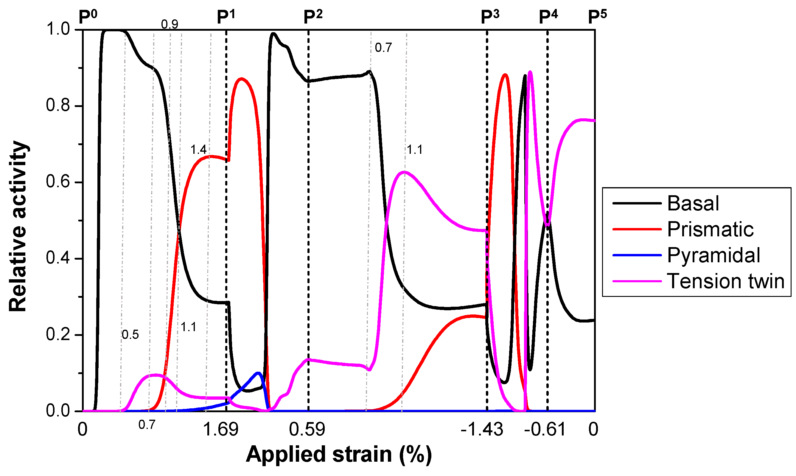
Figure 8 presents the evolution of slip and twinning modes, predicted by the EVPSC-TDT model, in the TCT case. The relative activity of a deformation mode is defined by the ratio of its corresponding plastic shear rate to the total plastic shear rate summed over all the deformation modes considered. In the first loading process (P0 to P1), basal <a> slip starts to activate shortly after deformation starts and prevails in the early stage (ε < 0.5%), with its relative activity at ~100%. After that, tension twinning starts to contribute to the total plastic deformation with a low fraction below 10%. Prismatic <a> slip starts to contribute after a strain of 0.75%, and it overtakes tension twinning after a strain of 0.9% and basal <a> slip at a strain of 1.1%, respectively. It reaches its maximum of ~66% at a strain of 1.4% and slightly decreases due to the arising contribution from pyramidal <c+a> slip. At the end of this process, the relative activities of basal <a>, tension twinning, prismatic <a> slip, and pyramidal <c+a> slip are 28.5%, 3.5%, 66%, and 2%, respectively. The dominant role of prismatic <a> slip in the latter half of this process is consistent with the detected active operations of prismatic <a> slip by EBSD and transmission electron microscopy (TEM) measurements [45]. In the first unloading process (P1 to P2), the activities of prismatic <a> and pyramidal <c+a> slips quickly drop down after a short increase, followed by a rapid increase in basal slip and a moderate increase in tension twinning. At the end of this process, the relative activities of basal slip and twinning are, respectively, 86% and 14%. This means that the unloading anelastic behavior is mainly related to basal slip and tension twinning, which is consistent with the findings in previous studies [26,39].
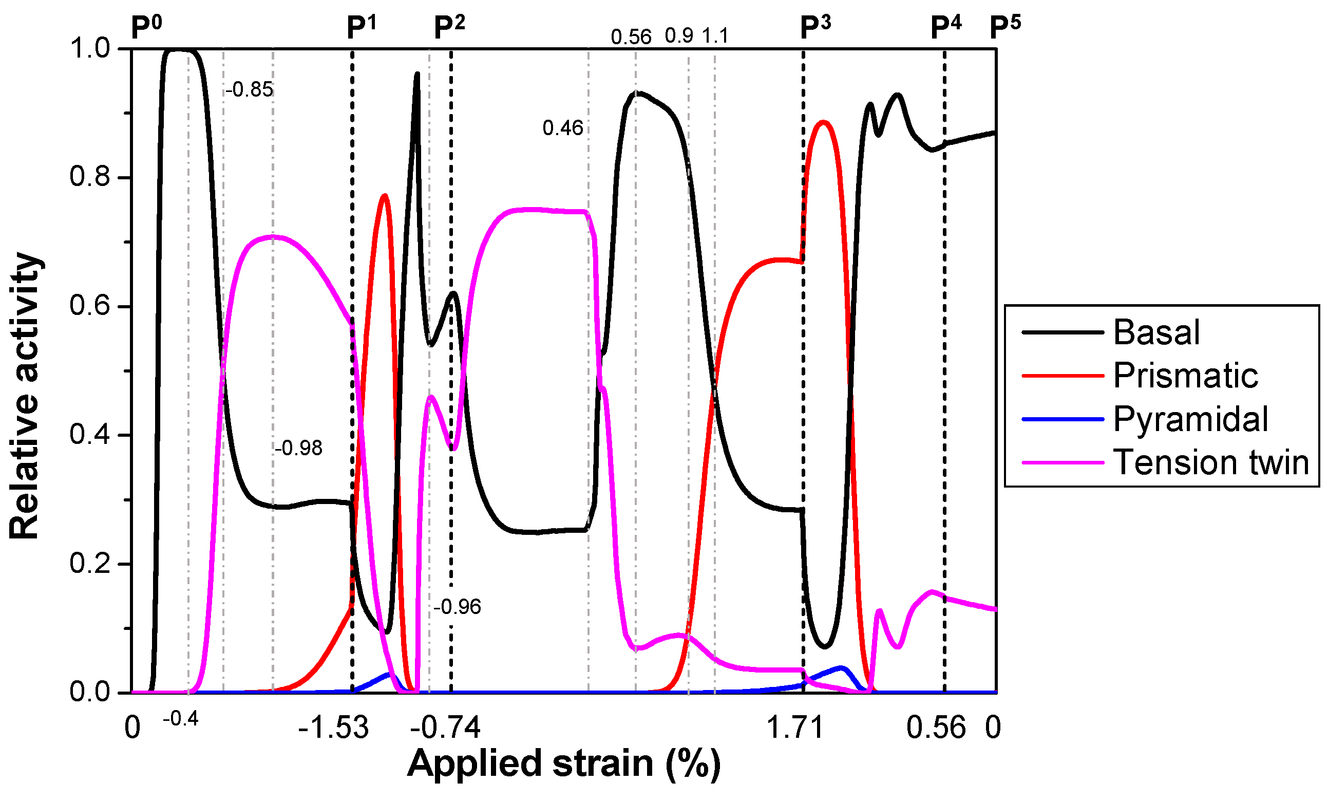
In the reverse compressive loading process (P2 to P3), basal <a> slip exhibits a slow increase in the starting stage (ε < 0.7%) until the activation of tension twinning and prismatic <a> slip, which start to operate at nearly the same strain level. In this process, tension twinning is the dominant deformation mode with a maximum relative activity of 63% at a strain of 1.1%, followed by the increasing contribution of prismatic slip. The prevailing role of tension twinning in this process is because most grains have an orientation favoring tension twinning under compression along the ED [32]. With the increasing number of grains having an orientation favoring prismatic <a> slip, this deformation mode starts to contribute increasingly as the applied strain increases. Pyramidal <c+a> slip hardly makes a contribution to total plastic deformation in this process due to its high activation stress. In the second unloading process (P3 to P4), basal <a> slip and tension twinning are still the two modes that dominate the unloading anelastic behavior. However, the maximum contribution of tension twinning is ~89%, mainly due to the detwinning process (see Figure 12). In the starting stage of the second reverse loading (P4 to P5), tension twinning remains an increasing tendency due to the prevailing role of detwinning in this process. The details of twinning–detwinning mechanisms will be discussed further in Section 4.4.
Figure 9 shows the predicted evolutions of slip and twinning modes in the CTC case. In the first compressive loading process (P0~P1), plastic deformation is only due to basal <a> slip in the early stage (ε < 0.4%) before tension twinning begins to contribute. Due to the favored texture, tension twinning overtakes basal <a> slip after a strain of 0.85% and reaches its maximum fraction of 71% at a strain of 0.98%. Then, it gradually decreases as prismatic <a> slip starts to increasingly contribute to the total plastic deformation. At the end of this process, the relative activities of basal <a> slip, tension twinning, and prismatic <a> slip are 29.5%, 57.5%, and 12.8%, respectively. Pyramidal <c+a> slip starts to operate close to the end of this loading process and finishes with an activity of 0.2%. Similar to the TCT case, the anelastic behavior during the first unloading process (P1~P2) is also attributed to the reversal movement of basal <a> dislocation slip and the detwinning behavior of tension twinning. However, the contribution from detwinning is much higher than that in the TCT case, with a maximum fraction of ~46% at a strain of 0.96%.
In the early stage (ε < 0.46%) of the reverse tensile loading process (P2~P3), only basal <a> slip and tension twinning contribute to the total plastic deformation, with a respective fraction of 25% and 75% at a strain of 0.46%. After that, the activity of basal <a> slip increases rapidly to 93% at a strain of 0.56%, followed by the increasing contribution from prismatic <a> slip, which surpasses tension twinning at a strain of 0.9% and basal <a> slip at a strain of 1.1%, respectively. At the end of this process (P3), the relative activities of basal <a> slip, tension twinning, and prismatic <a> slip are 28.4%, 3.5%, and 66.9%, respectively, and that of pyramidal <c+a> slip is 1.2%. In the second unloading process (P3~P4), the relative activities of basal <a> and tension twinning are similar to those in the first unloading process (P1~P2) of the TCT case, and they are, respectively, 85% and 15% at the end of this process (P4). In the second compressive loading process, these two modes still prevail until the end (P5).

4.4. Twinning–Detwinning Behavior and Evolution of Textures

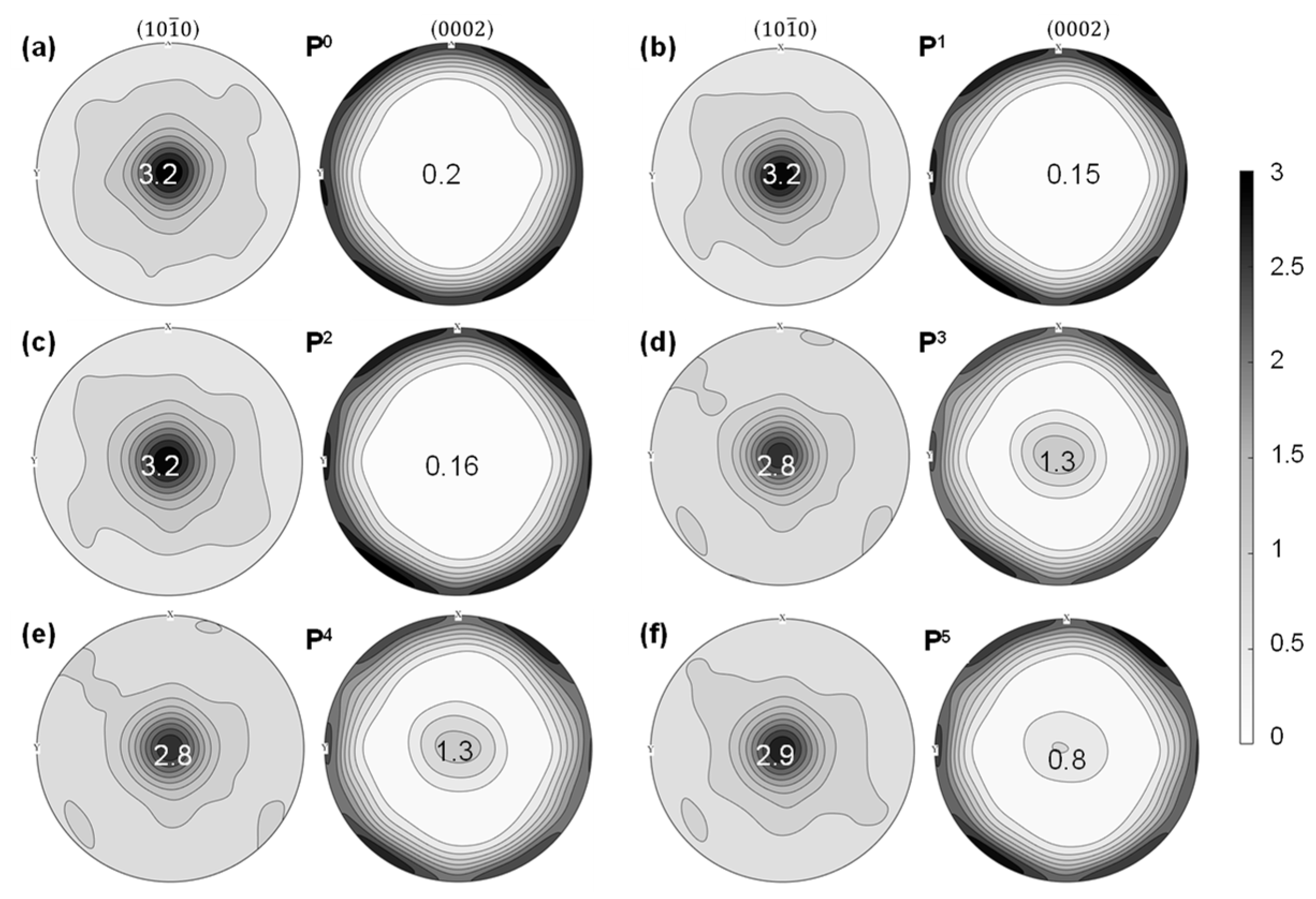
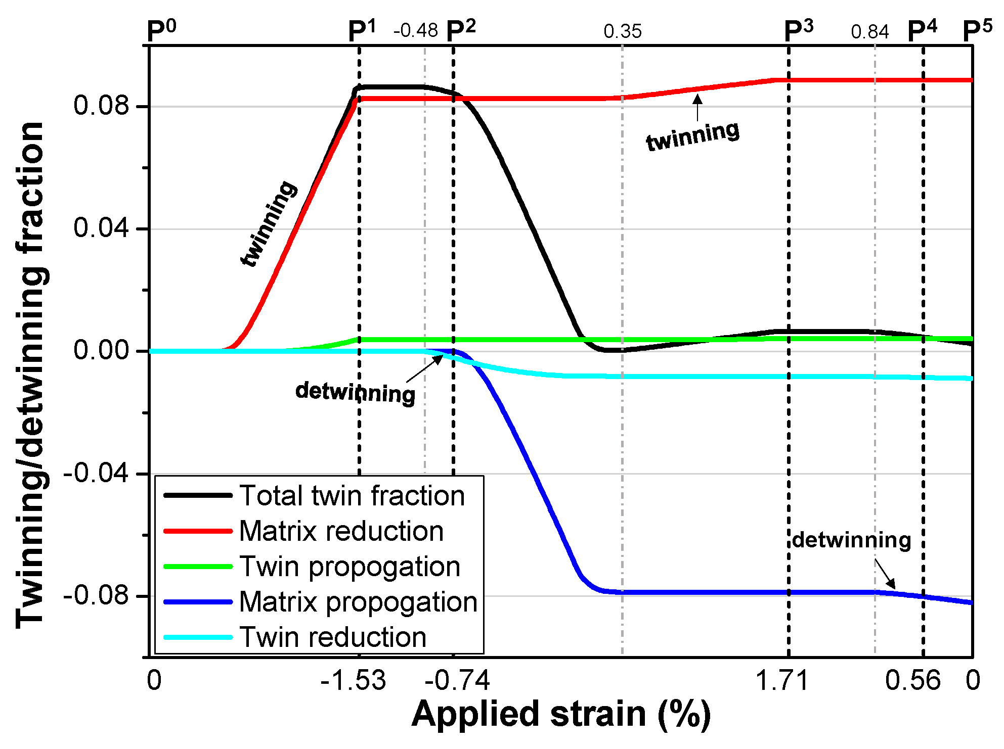
It is well known that tension twinning can cause a sudden orientation change of a grain by ~86.3°; thus, profuse twinning/detwinning activity will cause apparent changes in crystallographic texture. Figure 10 shows the evolution of the four twinning/detwinning mechanisms, i.e., matrix reduction (MR), twin propagation (TP), twin reduction (TR), and matrix propagation (MP), represented by the relevant accumulated twin fractions during plastic deformation, in the TCT case. In the tensile loading process (P0~P1), the alloy experiences an obvious twinning process, which is also identifiable by the decrease in the (0002) pole intensity from 0.2 in Figure 11a to 0.15 in Figure 11b. In the first unloading process (P1~P2), detwinning behavior starts at a strain of 1.0% and continues until a strain level of 0.6% in the reverse loading process (P2~P3). Interestingly, the twinning behavior starts at a strain of 0.14 in this process, indicating the EVPSC model can accurately differentiate stress states in differently oriented grains. The early start of the twinning behavior is due to the alloy’s favored crystallographic texture for tension twinning under compressive loading in this process [20]. Moreover, it is also found that the increase in twin fraction is mainly due to MR, while the decrease in twin fraction is mainly a result of MP, both driven by the RSS in the matrix. The rapid increase in twinning behavior in this process is also evidenced by the (0002) pole intensity change from 0.16 in Figure 11c to 1.3 in Figure 11d. During unloading, detwinning behavior is not active. Still, it operates actively in the final tensile loading process, with the (0002) pole intensity decreasing quickly from 1.3 (P4) in Figure 11e to 0.8 (P5) in Figure 11f. At the end of the loading case (P5), the fraction of residual twins is predicted to be 5.72% by the model, which is consistent with the EBSD results presented in Figure 5 and Figure 6.
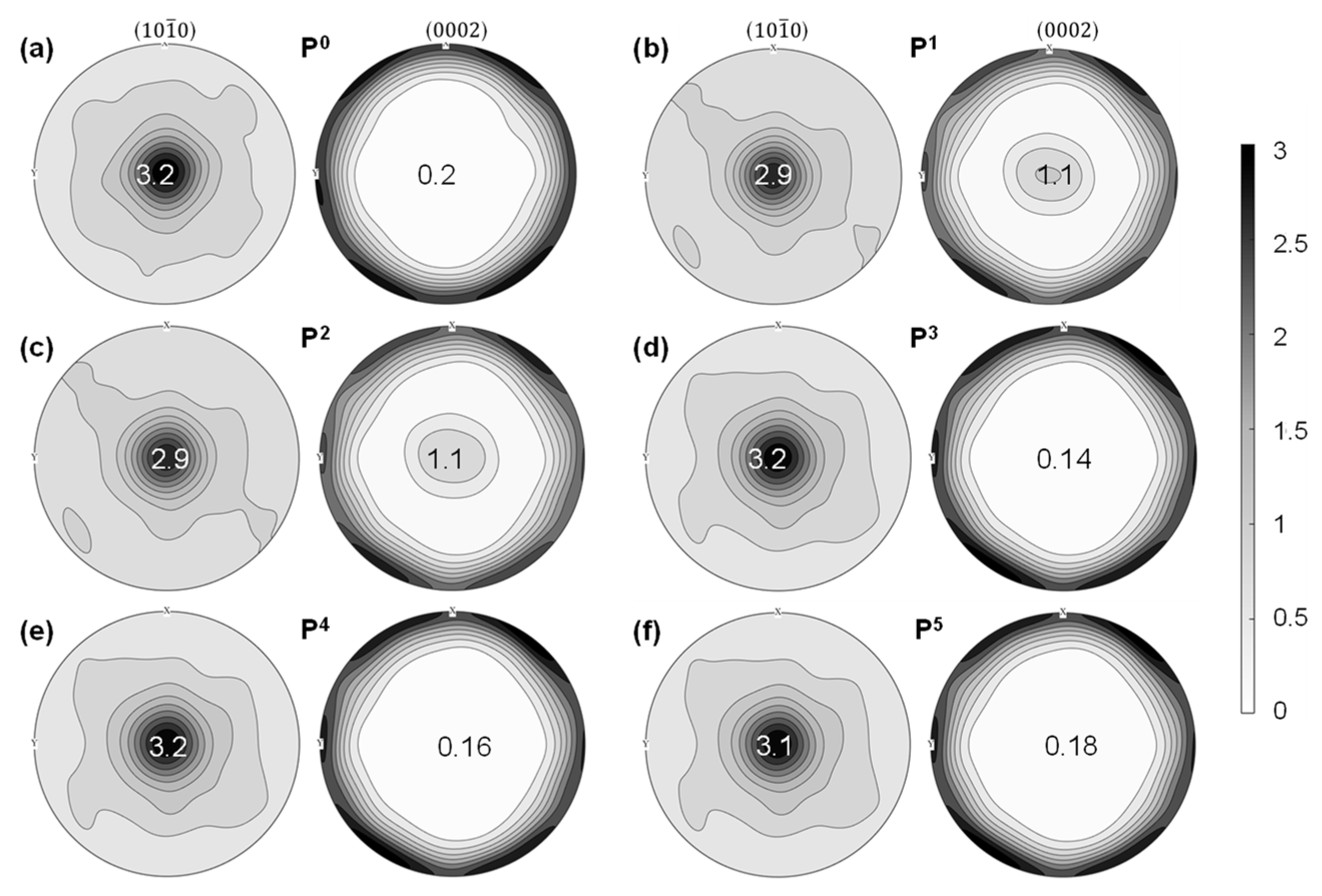
Figure 12 presents the evolution of the four mechanisms related to twinning/detwinning behavior in the CTC loading case, predicted by the EVPSC-TDT model. In the first compressive loading process (P0~P1), tension twinning is quite active because a majority of grains favor tension twinning under compressive loading along the ED, similar to that in the reverse compressive loading process (P2~P3) in the TCT case. In the first unloading process (P1~P2), detwinning behavior begins at a strain of −0.48%. It continues to the reverse tensile loading process (P2~P3), and a large portion of twinned grains experience detwinning in this process, indicated by the rapid decrease in total twin fraction in Figure 12. This pronounced detwinning behavior is quite different from that in the TCT case, which is believed to be the main reason for the large discrepancy from elastic behavior (Figure 3b) in this process [40]. Shortly after the detwinning process, twinning behavior starts to occur at a strain of 0.35% and continues to the end of this process. In the second unloading process (P3~P4), detwinning occurs at a strain of 0.84% and continues to the end of the loading case (P5). The final fraction of residual twins is predicted to be 0.26% by the EVPSC-TDT model. The twinning/detwinning behavior described above is also demonstrated by the (10 1 ¯ 1) and (0002) pole intensity changes in Figure 13. The predicted deformed texture of the alloy at the end of the loading case is validated by the EBSD results presented in Figure 5 and Figure 6. Although the model underestimates the detwinning behavior during the compressive unloading processes, the present model correctly differentiates the twinning/detwinning behaviors between the two loading cases. It is noteworthy to mention that the reverse tensile loading process (P2~P3) in the CTC case promotes more active detwinning behavior; thus, fewer twins remain at the end of this case (P5).
Table 3 compares the fractions of residual twins predicted by the EVPSC-TDT model using different 𝜿 values with experimental results in the two cases. It reveals that, with the increase of 𝜿, the fraction of residual twins also increases in the alloy. With a 𝜿 value of 0.75, the model predictions are quite close to the EBSD results. Meanwhile, as shown in Figure 7a,b, the predicting accuracy of the stress–strain behavior during the compressive unloading process is not improved. It has been shown in previous studies that back stresses induced by the twinning process make detwinning behavior easier to occur in the unloading process [40,41,44]. It is therefore inferred that the underestimation of detwinning behavior by the present model is believed to be the neglect of back stresses in the model, which can be improved to better predict the unloading behavior of Mg alloys.

5. Conclusions

The cyclic deformation behavior of a high-strength Mg-6Al-4Sn-2Zn-0.5Nd-0.5Ce alloy under TCT and CTC loading cycles has been investigated by experimental measurements and the EVPSC-TDT model. The following are the key conclusions drawn from the obtained results:
(1)
The as-aged alloy shows an equi-axis grain morphology, featuring an average grain size of 19.8 µm and a weakened basal texture. In contrast to conventional wrought alloys, this alloy displays reduced yielding asymmetry, with a tensile YS of 215 MPa and a compressive YS of 160 MPa. Its remarkable strength is attributed to the presence of Mg2Sn particles and Mg17Al12 precipitates.
(2)
The alloy exhibits pronounced anelastic behavior during unloading and reverse loading phases, owing to the reversal movements of basal <a> slip and detwinning activity. Notably, the deviation from elastic behavior is more prominent during compressive unloading and subsequent reverse tensile loading, facilitated by pre-existing twins formed during the initial compressive loading. After the loading cycles, the area fractions of residual twins are determined to be 7.51% and 0.93% in the TCT and CTC cases, respectively.
(3)
While the EVPSC-TDT model accurately predicts the overall stress–strain behavior during both loading cycles, it underestimates detwinning activity during compression unloading and the early stages of reverse tensile loading due to the model’s lack of consideration for back stresses. Initially, basal <a> slip governs plastic deformation in both loading cycles, succeeded by tension twinning after a strain of 0.85% in the CTC case and prismatic <a> slip after a strain of 1.1% in the TCT case. Basal <a> slip contributes over 85% of the anelastic plastic deformation during the tensile unloading process, while maximum tension twinning activity reaches 46% and 89% in the CTC and TCT cases, respectively, during compressive unloading.
(4)
The EVPSC-TDT model accurately predicts the deformed textures of the alloy after both loading cycles. It is observed that twinning and detwinning are primarily influenced by stresses in the matrix, allowing simultaneous occurrence during reverse loading due to distinct stress states among different grains. Variations in the fractions of residual twins between the two cases are attributed to differing unloading and reverse loading sequences.

Author Contributions

Conceptualization, H.W. and B.L.; methodology, H.W., X.X. and M.S.; software, H.W.; validation, H.W., Y.Y. and M.S.; formal analysis and investigation, H.W. and Y.Y.; resources, H.W. and B.L.; data curation, X.X. and M.S.; writing—original draft preparation, H.W.; writing—review and editing, Y.Y., B.L., M.S. and X.X.; funding acquisition, H.W. All authors have read and agreed to the published version of the manuscript.

Funding

This research was funded by the Natural Science Foundation of Shandong Province, China (No. ZR2022QE206).

Data Availability Statement

The raw data supporting the conclusions of this article will be made available by the authors on request.

Conflicts of Interest

The authors declare no conflicts of interest.

References

  1. Wang, X.J.; Xu, D.K.; Wu, R.Z.; Chen, X.B.; Peng, Q.M.; Jin, L.; Xin, Y.C.; Zhang, Z.Q.; Liu, Y.; Chen, X.H.; et al. What Is Going on in Magnesium Alloys? J. Mater. Sci. Technol. 2018, 34, 245–247. [Google Scholar] [CrossRef]
  2. Jin, Z.-Z.; Zha, M.; Wang, S.-Q.; Wang, S.-C.; Wang, C.; Jia, H.-L.; Wang, H.-Y. Alloying Design and Microstructural Control Strategies towards Developing Mg Alloys with Enhanced Ductility. J. Magnes. Alloys 2022, 10, 1191–1206. [Google Scholar] [CrossRef]
  3. Nie, J.-F. Precipitation and Hardening in Magnesium Alloys. Met. Mater. Trans. A 2012, 43, 3891–3939. [Google Scholar] [CrossRef]
  4. Homma, T.; Kunito, N.; Kamado, S. Fabrication of Extraordinary High-Strength Magnesium Alloy by Hot Extrusion. Scr. Mater. 2009, 61, 644–647. [Google Scholar] [CrossRef]
  5. Wu, Z.; Ahmad, R.; Yin, B.; Sandlöbes, S.; Curtin, W.A. Mechanistic Origin and Prediction of Enhanced Ductility in Magnesium Alloys. Science 2018, 359, 447–452. [Google Scholar] [CrossRef] [PubMed]
  6. Pan, H.; Kang, R.; Li, J.; Xie, H.; Zeng, Z.; Huang, Q.; Yang, C.; Ren, Y.; Qin, G. Mechanistic Investigation of a Low-Alloy Mg–Ca-Based Extrusion Alloy with High Strength–Ductility Synergy. Acta Mater. 2020, 186, 278–290. [Google Scholar] [CrossRef]
  7. Jiang, B.; Dong, Z.; Zhang, A.; Song, J.; Pan, F. Recent Advances in Micro-Alloyed Wrought Magnesium Alloys: Theory and Design. Trans. Nonferrous Met. Soc. China 2022, 32, 1741–1780. [Google Scholar] [CrossRef]
  8. Sabat, R.K.; Brahme, A.P.; Mishra, R.K.; Inal, K.; Suwas, S. Ductility Enhancement in Mg-0.2%Ce Alloys. Acta Mater. 2018, 161, 246–257. [Google Scholar] [CrossRef]
  9. Zhang, J.; Peng, P.; Luo, A.A.; She, J.; Tang, A.; Pan, F. Dynamic Precipitation and Enhanced Mechanical Properties of ZK60 Magnesium Alloy Achieved by Low Temperature Extrusion. Mater. Sci. Eng. A 2022, 829, 142143. [Google Scholar] [CrossRef]
  10. Dong, X.; Fu, J.; Wang, J.; Yang, Y. Microstructure and Tensile Properties of As-Cast and as-Aged Mg–6Al–4Zn Alloys with Sn Addition. Mater. Des. 2013, 51, 567–574. [Google Scholar] [CrossRef]
  11. Yan, T.; Pei, D.; Cheng, M.; Liang, Z.; Li, X.; Wang, X. Development of Mg–6Al–4Sn–1Zn Alloy Sheets with Ultra-High Strength by Combining Extrusion and High-Speed Rolling. J. Mater. Res. Technol. 2024, 29, 1487–1497. [Google Scholar] [CrossRef]
  12. Ma, C.-Y.; Xia, N.; Wang, C.; Li, M.-X.; Hua, Z.-M.; Ren, M.-W.; Wang, H.-Y. A Novel Mg-5Al-2Zn-2Sn Alloy with High Strength-Ductility Synergy Fabricated via Simple Hot Rolling and Annealing Treatment. J. Alloys Compd. 2021, 869, 159308. [Google Scholar] [CrossRef]
  13. Park, S.H.; Jung, J.-G.; Yoon, J.; You, B.S. Influence of Sn Addition on the Microstructure and Mechanical Properties of Extruded Mg–8Al–2Zn Alloy. Mater. Sci. Eng. A 2015, 626, 128–135. [Google Scholar] [CrossRef]
  14. Wang, H.; Rong, J.; Liu, G.; Zha, M.; Wang, C.; Luo, D.; Jiang, Q. Effects of Zn on the Microstructure and Tensile Properties of As-Extruded Mg-8Al-2Sn Alloy. Mater. Sci. Eng. A 2017, 698, 249–255. [Google Scholar] [CrossRef]
  15. Wang, L.; Huang, G.; Quan, Q.; Bassani, P.; Mostaed, E.; Vedani, M.; Pan, F. The Effect of Twinning and Detwinning on the Mechanical Property of AZ31 Extruded Magnesium Alloy during Strain-Path Changes. Mater. Des. 2014, 63, 177–184. [Google Scholar] [CrossRef]
  16. Song, B.; Guo, N.; Liu, T.; Yang, Q. Improvement of Formability and Mechanical Properties of Magnesium Alloys via Pre-Twinning: A Review. Mater. Des. 2014, 62, 352–360. [Google Scholar] [CrossRef]
  17. Hu, J.; Nie, X.; Fu, S.; Liu, Z.; Gao, H. Effects of Pre-Compression Modes on Mechanical Properties and Fatigue Behaviors of Rolled ZK60 Magnesium Alloy. Int. J. Fatigue 2024, 183, 108235. [Google Scholar] [CrossRef]
  18. Drozdenko, D.; Bohlen, J.; Yi, S.; Minárik, P.; Chmelík, F.; Dobroň, P. Investigating a Twinning–Detwinning Process in Wrought Mg Alloys by the Acoustic Emission Technique. Acta Mater. 2016, 110, 103–113. [Google Scholar] [CrossRef]
  19. Zhang, H.; Jérusalem, A.; Salvati, E.; Papadaki, C.; Fong, K.S.; Song, X.; Korsunsky, A.M. Multi-Scale Mechanisms of Twinning-Detwinning in Magnesium Alloy AZ31B Simulated by Crystal Plasticity Modeling and Validated via in Situ Synchrotron XRD and in Situ SEM-EBSD. Int. J. Plast. 2019, 119, 43–56. [Google Scholar] [CrossRef]
  20. Wu, L.; Jain, A.; Brown, D.W.; Stoica, G.M.; Agnew, S.R.; Clausen, B.; Fielden, D.E.; Liaw, P.K. Twinning–Detwinning Behavior during the Strain-Controlled Low-Cycle Fatigue Testing of a Wrought Magnesium Alloy, ZK60A. Acta Mater. 2008, 56, 688–695. [Google Scholar] [CrossRef]
  21. Zhu, Y.; Hou, D.; Li, Q. Quasi In-Situ EBSD Analysis of Twinning-Detwinning and Slip Behaviors in Textured AZ31 Magnesium Alloy Subjected to Compressive-Tensile Loading. J. Magnes. Alloys 2022, 10, 956–964. [Google Scholar] [CrossRef]
  22. Lou, X.Y.; Li, M.; Boger, R.K.; Agnew, S.R.; Wagoner, R.H. Hardening Evolution of AZ31B Mg Sheet. Int. J. Plast. 2007, 23, 44–86. [Google Scholar] [CrossRef]
  23. Bong, H.J.; Lee, J.; Lee, M.-G. Modeling Crystal Plasticity with an Enhanced Twinning–Detwinning Model to Simulate Cyclic Behavior of AZ31B Magnesium Alloy at Various Temperatures. Int. J. Plast. 2022, 150, 103190. [Google Scholar] [CrossRef]
  24. Guo, X.; Cheng, Y.; Xin, Y.; Wu, W.; Ma, C.; An, K.; Liaw, P.K.; Wu, P.; Liu, Q. Crystal Plasticity Modeling of Low-Cycle Fatigue Behavior of an Mg-3Al-1Zn Alloy Based on a Model, Including Twinning and Detwinning Mechanisms. J. Mech. Phys. Solids 2022, 168, 105030. [Google Scholar] [CrossRef]
  25. Li, H.; Yu, C.; Kang, G. Crystal Plasticity Modeling of the Multiaxial Ratchetting of Extruded AZ31 Mg Alloy. Int. J. Plast. 2022, 152, 103242. [Google Scholar] [CrossRef]
  26. Wang, H.; Lee, S.Y.; Wang, H.; Woo, W.; Huang, E.-W.; Jain, J.; An, K. On Plastic Anisotropy and Deformation History-Driven Anelasticity of an Extruded Magnesium Alloy. Scr. Mater. 2020, 176, 36–41. [Google Scholar] [CrossRef]
  27. Han, L.; Yu, Y.; Wei, D.; Wang, X.; Zhao, G.; Wang, G. The Synergistic and Interactive Effects of Slip Systems and Dynamic Recrystallization on the Weakening Basal Texture of Mg-Y-Nd-Zr-Gd Magnesium Alloy. Mater. Des. 2024, 237, 112583. [Google Scholar] [CrossRef]
  28. Wang, S.; Gao, F.-H.; Lv, B.-J.; Cui, N.; Guo, F. Effects of 0.5 Wt.% Nd Addition on the Microstructure and Mechanical Properties of As-Extruded and Aged Mg-6Al-3Sn-2Zn Alloys. J. Mater. Eng. Perform 2023, 32, 2635–2645. [Google Scholar] [CrossRef]
  29. Park, S.H.; Jung, J.-G.; Kim, Y.M.; You, B.S. A New High-Strength Extruded Mg-8Al-4Sn-2Zn Alloy. Mater. Lett. 2015, 139, 35–38. [Google Scholar] [CrossRef]
  30. ASTM E606/E606M-21; Standard Test Method for Strain-Controlled Fatigue Testing. ASTM Standards: West Conshohocken, PA, USA, 2021.
  31. Wang, H.; Wu, P.D.; Wang, J.; Tomé, C.N. A Crystal Plasticity Model for Hexagonal Close Packed (HCP) Crystals Including Twinning and de-Twinning Mechanisms. Int. J. Plast. 2013, 49, 36–52. [Google Scholar] [CrossRef]
  32. Barnett, M.R. Twinning and the Ductility of Magnesium Alloys: Part I: “Tension” Twins. Mater. Sci. Eng. A 2007, 464, 1–7. [Google Scholar] [CrossRef]
  33. Lebensohn, R.A.; Tomé, C.N. A Self-Consistent Anisotropic Approach for the Simulation of Plastic Deformation and Texture Development of Polycrystals: Application to Zirconium Alloys. Acta Metall. Mater. 1993, 41, 2611–2624. [Google Scholar] [CrossRef]
  34. Wang, H.; Raeisinia, B.; Wu, P.D.; Agnew, S.R.; Tomé, C.N. Evaluation of Self-Consistent Polycrystal Plasticity Models for Magnesium Alloy AZ31B Sheet. Int. J. Solids Struct. 2010, 47, 2905–2917. [Google Scholar] [CrossRef]
  35. Wang, H.; Lee, S.Y.; Gharghouri, M.A.; Wu, P.D.; Yoon, S.G. Deformation Behavior of Mg-8.5wt.%Al Alloy under Reverse Loading Investigated by in-Situ Neutron Diffraction and Elastic Viscoplastic Self-Consistent Modeling. Acta Mater. 2016, 107, 404–414. [Google Scholar] [CrossRef]
  36. Qiao, H.; Agnew, S.R.; Wu, P.D. Modeling Twinning and Detwinning Behavior of Mg Alloy ZK60A during Monotonic and Cyclic Loading. Int. J. Plast. 2015, 65, 61–84. [Google Scholar] [CrossRef]
  37. Fang, Z.; Guo, T.; Wang, Y.; Li, Z. Dynamic Strength Differential and Bauschinger Effects in an Extruded AZ80 Magnesium Alloy. J. Mater. Res. Technol. 2024, 30, 5990–6002. [Google Scholar] [CrossRef]
  38. Xie, D.; Lyu, Z.; Li, Y.; Liaw, P.K.; Chew, H.B.; Ren, Y.; Chen, Y.; An, K.; Gao, Y. In Situ Monitoring of Dislocation, Twinning, and Detwinning Modes in an Extruded Magnesium Alloy under Cyclic Loading Conditions. Mater. Sci. Eng. A 2021, 806, 140860. [Google Scholar] [CrossRef]
  39. Lee, S.Y.; Wang, H.; Gharghouri, M.A.; Nayyeri, G.; Woo, W.; Shin, E.; Wu, P.D.; Poole, W.J.; Wu, W.K. An Deformation Behavior of Solid-Solution-Strengthened Mg–9 Wt.% Al Alloy: In Situ Neutron Diffraction and Elastic–Viscoplastic Self-Consistent Modeling. Acta Mater. 2014, 73, 139–148. [Google Scholar] [CrossRef]
  40. Wang, H.; Wu, P.D.; Wang, J. Modeling Inelastic Behavior of Magnesium Alloys during Cyclic Loading–Unloading. Int. J. Plast. 2013, 47, 49–64. [Google Scholar] [CrossRef]
  41. Lee, S.Y.; Gharghouri, M.A. Pseudoelastic Behavior of Magnesium Alloy during Twinning-Dominated Cyclic Deformation. Mater. Sci. Eng. A 2013, 572, 98–102. [Google Scholar] [CrossRef]
  42. Muránsky, O.; Carr, D.G.; Šittner, P.; Oliver, E.C. In Situ Neutron Diffraction Investigation of Deformation Twinning and Pseudoelastic-like Behaviour of Extruded AZ31 Magnesium Alloy. Int. J. Plast. 2009, 25, 1107–1127. [Google Scholar] [CrossRef]
  43. Hama, T.; Takuda, H. Crystal-Plasticity Finite-Element Analysis of Inelastic Behavior during Unloading in a Magnesium Alloy Sheet. Int. J. Plast. 2011, 27, 1072–1092. [Google Scholar] [CrossRef]
  44. Zhang, X.; Zhou, K.; Wang, H.; Jiang, Y.; Sun, X.; Liu, C.; Yu, Q.; Jiang, Y.; Wu, P.; Wang, H. On the Cyclic Torsion Behavior of Extruded AZ61A Magnesium Alloy Tube. Int. J. Fatigue 2023, 174, 107704. [Google Scholar] [CrossRef]
  45. Suh, B.-C.; Kim, J.H.; Bae, J.H.; Hwang, J.H.; Shim, M.-S.; Kim, N.J. Effect of Sn Addition on the Microstructure and Deformation Behavior of Mg-3Al Alloy. Acta Mater. 2017, 124, 268–279. [Google Scholar] [CrossRef]
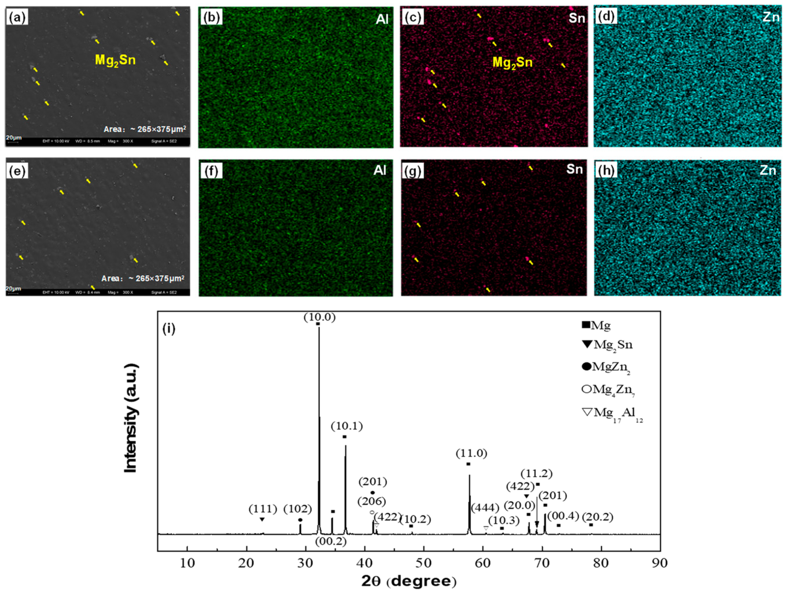
Figure 1. Region 1: (a) SEM image, (b) distribution of Al element, (c) distribution of Sn element, and (d) distribution of Zn element; Region 2: (e) SEM image, (f) distribution of Al element, (g) distribution of Sn element, and (h) distribution of Zn element; (i) XRD diffraction pattern. Note: yellow arrows are used to highlight the existence of Mg2Sn particles.
Metals 14 00635 g001
Figure 2. Geometric dimensions of the specimen used in loading reversal tests.
Metals 14 00635 g002
Figure 3. Engineering stress–strain curves of the alloy in the two cases: (a) TCT and (b) CTC.
Metals 14 00635 g003
Figure 4. Initial microstructure and crystallographic texture of the alloy: (a) inverse pole figure map; (b) (10 1 ¯ 0) and (0002) pole figures; (c) grain boundary map; and (d) statistical distribution of kernel average misorientations.
Metals 14 00635 g004
Figure 5. Microstructures of the deformed specimens: (a) IPF map in TCT; (b) grain boundary map in TCT; (c) IPF map in CTC; and (d) grain boundary map in CTC. Note: yellow arrows represent the slip traces by plastic deformation.
Metals 14 00635 g005
Figure 6. Poles figures of (10 1 ¯ 0) and (0002) planes: (a,c) TCT and (b,d) CTC.
Metals 14 00635 g006
Figure 7. Experimental and predicted stress–strain curves of the alloy: (a) TCT and (b) CTC.
Metals 14 00635 g007
Figure 8. Evolution of different slip and twinning modes in the TCT case.
Metals 14 00635 g008
Figure 9. Evolution of different slip and twinning modes in the CTC case.
Metals 14 00635 g009
Figure 10. Evolution of twin/detwinning behavior in the TCT case.
Metals 14 00635 g010
Figure 11. Evolution of crystallographic textures at different stages in the TCT case: (a) P0, (b)P1, (c) P2,(d) P3,(e) P4, and (f) P5.
Metals 14 00635 g011
Figure 12. Evolution of twin/detwinning behavior in the CTC case.
Metals 14 00635 g012
Figure 13. Evolution of crystallographic textures at different stages in the CTC case: (a) P0, (b) P1, (c) P2, (d) P3, (e) P4, and (f) P5.
Metals 14 00635 g013
Table 1. Chemical composition of the studied alloy (in wt.%).
AlSnZnNdCeMg
Nominal6.004.002.000.500.50Bal.
Region 15.503.962.200.630.40Bal.
Region 25.464.032.220.41Bal.
Table 2. Calibrated hardening parameters for different slip and twinning systems (unit: MPa, except for A and B).
τ 0 τ 1 θ 0 θ 1 AB
Basal <a>38303000--
Prismatic <a>105453000--
Pyramidal <c+a>1209010000--
Tension twin660000.60.7
Table 3. Predictions of the fraction of residual twins with different 𝜿 values.
𝜿 = 0.35𝜿 = 0.55𝜿 = 0.75EBSD
TCT3.83%5.72%7.17%7.51%
CTC0.24%0.26%0.36%0.93%
Disclaimer/Publisher’s Note: The statements, opinions and data contained in all publications are solely those of the individual author(s) and contributor(s) and not of MDPI and/or the editor(s). MDPI and/or the editor(s) disclaim responsibility for any injury to people or property resulting from any ideas, methods, instructions or products referred to in the content.