Article

Microstructure and Pore Characteristics of a Double-Layered Pore Structure Powder Filter Fabricated by the WPS Process

1
Metal Powder Department, Korea Institute of Materials Science (KIMS), Changwon 51508, Republic of Korea
2
School of Materials Science and Engineering, Pusan National University, Busan 46241, Republic of Korea
3
ASFLOW Co., Ltd., Hwaseong 16648, Republic of Korea
*
Authors to whom correspondence should be addressed.
Metals 2024, 14(6), 665; https://doi.org/10.3390/met14060665
Submission received: 23 April 2024 / Revised: 30 May 2024 / Accepted: 31 May 2024 / Published: 4 June 2024
(This article belongs to the Special Issue Advances in Powder Metallurgy of Light Alloys)

Abstract

:
In order to supply high-purity process gas in the semiconductor manufacturing process, a gas filter is used to remove particles that may be contained in the gas. However, because the gas filters currently in use have simple pore structures, there is a need to increase filtration efficiency through the development of filters with complex pore structures. In this study, a metal powder filter with double-layered pores was manufactured using a Wet Powder Spraying process (WPS) to increase the filtering efficiency of gas filters used in semiconductor manufacturing. The effects of the mixing ratio of spherical-shape and flake-shape powders and the rolling process on the filter’s characteristics were investigated. The filter’s performance, microstructure, and surface roughness were evaluated by measuring porosity and gas permeability. The results showed that as the ratio of flake-shaped powder decreased, the thickness of the coating layer and the porosity of the filter decreased. Additionally, it was observed that as the rolling process progressed, the non-uniform pore structure was oriented parallel to the cross-section of the filter regardless of the mixing ratio. Measurements found that the gas permeability of the uncoated filter support was the highest, and that gas permeability decreased as the proportion of spherical powder increased regardless of the average particle size of the mixed powder. Lower gas permeability was observed in rolled samples. A filtration efficiency of LRV 3 or higher was confirmed.

1. Introduction

A porous metal is a metal that contains numerous voids or pores within its structure. Depending on the structure of the pores in the material, porous metals can be classified as open pore or closed pore types. The properties of the porous metal vary depending on their pore size, pore orientation, and porosity [1,2]. Porous metals with closed pores exhibit high compressive strength, stiffness, buoyancy, and impact absorption [3]. On the other hand, porous metals with open pores have a high specific surface area and permeability [4]. The controlled manipulation of these pore characteristics has led to diverse applications in various fields, including lightweight structures, vibration control, sound absorption, energy absorption, biomaterials, heat exchangers, filters, catalysts, and more [5]. Porous metals with open pores are frequently used as filters and employed to separate different fluids or remove impurities with applications in chemical, automotive, and semiconductor industries for catalysis, waste removal, and gas purification [1,6,7,8,9,10,11,12].
With the rapid advancement of the semiconductor industry, there is an increasing demand for the purification of process gases used in semiconductor manufacturing processes. In order to supply high-purity process gases, it is necessary to remove impurity particles that may be contained in the gas and supply high-purity gases. Therefore, the development of gas filters with high filtration efficiency that can be used in semiconductor manufacturing is crucial. This fluid separation ability is closely related to pressure drop, and structures with an uneven pore volume distribution can achieve lower pressure drop [4,13,14,15,16]. Additionally, the filter efficiency increases as the flow path of the fluid becomes longer or narrower [17]. To achieve high filtration efficiency, it is crucial to develop metal filters with complex pore structures.
The materials used for metal filters include metal mesh, metal fibers, and metal powder sintered materials. Metal mesh has the advantage of being cost-effective but has lower capture efficiency, which makes it a challenge to filter fine particles [18]. Metal fibers typically possess about 60% porosity, and ultrafine fibers need to be used to filter fine particles, which can be very expensive [19]. On the other hand, metal powder sintered materials can have a wide range of particle sizes, from fine to large particles, and allow the fabrication of metal filters with complex pore structures through the use of foaming agents, particle size control, heat treatment or coating, and heating rate control [3,20,21,22].
There are various methods for manufacturing metal powder filters with metal powders, including slurry coating [23,24], the space holder method [25], impregnation method [26], hot isostatic pressing [27], selective laser melting [28], binder jetting [29], and the Wet Powder Spraying process (WPS) [30,31,32]. Among the mentioned methods, the WPS process is a simple method in which a metal powder slurry is sprayed onto a substrate using an automated spray gun and carrier gas. Through subsequent sintering processes, the binder is burned and the coating layer is densified. In general, metal powder filter manufacturing methods (e.g., slurry coating, space-holder method, impregnation) have high process cost and material limitation because there are de-binding and sintering processes. And it is difficult to manufacture a shape with a complex flow path. However, the WPS process is relatively simple compared to other processes because there is no de-binding process, and it can be applied to a wide range of shapes and sizes, including plates, tubes, nanomaterials, and large-scale structures [33,34,35,36,37]. Despite these advantages, there is limited information available, as there has been relatively little research.
To develop and optimize the WPS process, various process parameters need to be considered, including the type of powder, binder concentration, slurry supply rate, nozzle type, distance between the nozzle tip and the specimen, nozzle traverse speed, coating time, and heat treatment. Previous studies have investigated the influence of these parameters on the overall coating results. Due to the extensive process variables involved, the experimental designs have typically been developed using an empirical approach. Based on multiple experimental results, improvements have been made in terms of nozzle type, binder type and concentration, slurry ratio, spray distance, nozzle traverse speed, gas pressure, and drying time, providing reproducible results [30,31,32,33,34].
To be used as a metal filter, a porous metal needs to withstand high temperature, high pressure, and harsh conditions. For this reason, materials such as stainless steel, nickel, and Hastelloy are commonly used. Research on stainless steel-based filters has mainly focused on 316L stainless steel [19,24].
In this study, a new technology called the WPS process was used to manufacture a metal powder filter with a double-layered pore structure in which a coarse pore layer and a micro-pore layer were mixed. Then, SUS316L metal powders of the two shapes were mixed to prepare a slurry according to the mixing ratio and coated on a tube-type filter support through a WPS process to investigate the effect of the powder shape on the double-layered pore structure (DLP) powder filter. Additionally, the filters’ characteristics such as gas permeability and filter particle efficiency were calculated along with their microstructure.

2. Materials and Methods
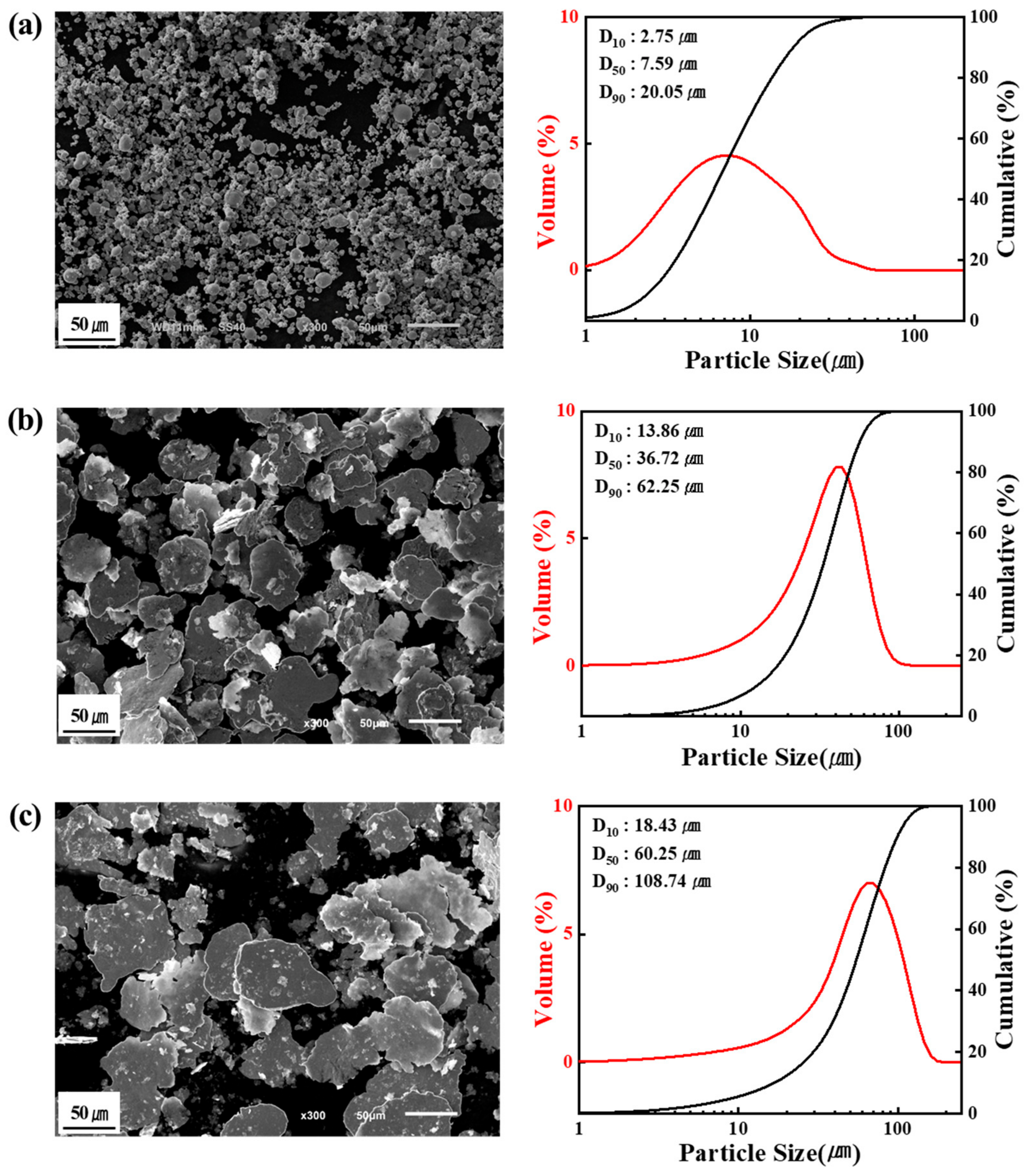
2.1. Materials

The spherical powders used as raw materials for SUS316L were manufactured using a gas atomization process, had an average particle size of 8 μm, and were obtained from ATMIX (HPF-13F, Aomori, Japan). Flake metal powders were obtained from NOVAMET (STANDARD, FINE, Lebanon, TN, USA). Particle size of the fine flake was 37 μm, while the standard flake had a particle size of 60 μm. The shapes and average particle sizes of the three powders are shown in Figure 1. In the graph, the black line represents the cumulative value of particles occupied by size and is related to the Y-axis (right). The red line represents the amount of particles occupied by size and is related to the Y-axis (left). The chemical compositions are presented in Table 1.

2.2. Production Process

DLP powder filter samples were manufactured using the WPS process, and an overview of the manufacturing process is shown in Figure 2. The detailed experimental procedure is as follows. The WPS process conditions are illustrated in Table 2. The spherical powder and flake powder were mixed at different weight ratios, and during the mixing process, ethanol and binder were added to produce a slurry. During the process, the spherical powder was mixed with flake powder at weight ratios of 25 wt.% and 50 wt.% to evaluate the effect of mixing ratio on physical properties, and these samples were named 75F25S and 50F50S, respectively. The prepared slurry was stirred at 400 rpm for 30 min to enhance dispersion stability. The prepared slurry was coated onto a tube-type filter support (Φ30 mm × 70 mm) using the WPS process and then dried in air for one hour. Generally, the sintering temperature of the flake powder coating layer is 900~1200 °C [38]. If the sintering temperature is less than 600 °C, the binder is not sufficiently removed and, the sintering between the powder and the support is not sufficiently achieved. And when the sintering temperature exceeds 1300 °C, the flake shape disappears during the sintering process, and the pore size and porosities of the coating layer decreases. If the sintering time is less than 30 min, the binder is not sufficiently removed, and if the sintering time exceeds 120 min, the flake shape disappears [39]. For this reason, in a previous study [40], the sintering temperature was set to 1050 °C when manufacturing porous metal using flake powder. Moreover, if the heating and cooling rates are very high (i.e., more than 10 °C/min), defects may occur due to the rapid volatilization of the binder contained in the specimen. So, in this study, the dried DLP powder filter was sintered at 1050 °C for one hour under a vacuum atmosphere (<5 × 10⁻⁵ torr), and the heating and cooling rates were set to 5 °C/min. The sintering process is shown in Figure 3. Finally, the sample surface was subjected to a rolling process.

2.3. Characterization of DLP Powder Filter Samples

The average particle sizes of the spherical powder and flake powder were analyzed using a laser particle size analyzer (LS13, Beckman Coulter, Brea, CA, USA) under dry atmospheric conditions. The manufactured DLP powder filter samples were cut and polished to observe their microstructure. The microstructure was observed using an optical microscope (Nikon ECLIPSE MA200, Tokyo, Japan). Then, a rolling process was performed for 5 min, and the variations in thickness and surface roughness were measured. The surface roughness was measured in four places in the circumferential direction using a surface roughness tester (SJ-410, Mitutoyo, Kawasaki, Japan), and the surface roughness value (Ra) was shown as an average value.
To investigate the characteristics of the filter, the porosity and pore distribution were measured using an image analysis program (iSolution DTx64) that determines the contrast difference in optical microscope (OM) images. The gas permeability characteristics of the filter were examined by introducing air through the DLP powder filter sample using a capillary flow porometer (CFP1200AEL, Porous Material Inc., Ithaca, NY, USA), and the amount of air passing through the filter was measured quantitatively. Additionally, the particle filtration efficiency of the filter was evaluated by numerically calculating the number of particles that could be removed. The filtration performance test was conducted in a 1000 class cleanroom from ASFLOW Inc. (Hwaseong, Republic of Korea) into which 99.99% purity nitrogen gas and NaCl particles with an average particle diameter of 70 nm were introduced. The particle counts in the upstream and downstream were measured using a particle counter for calculation.

3. Results and Discussion
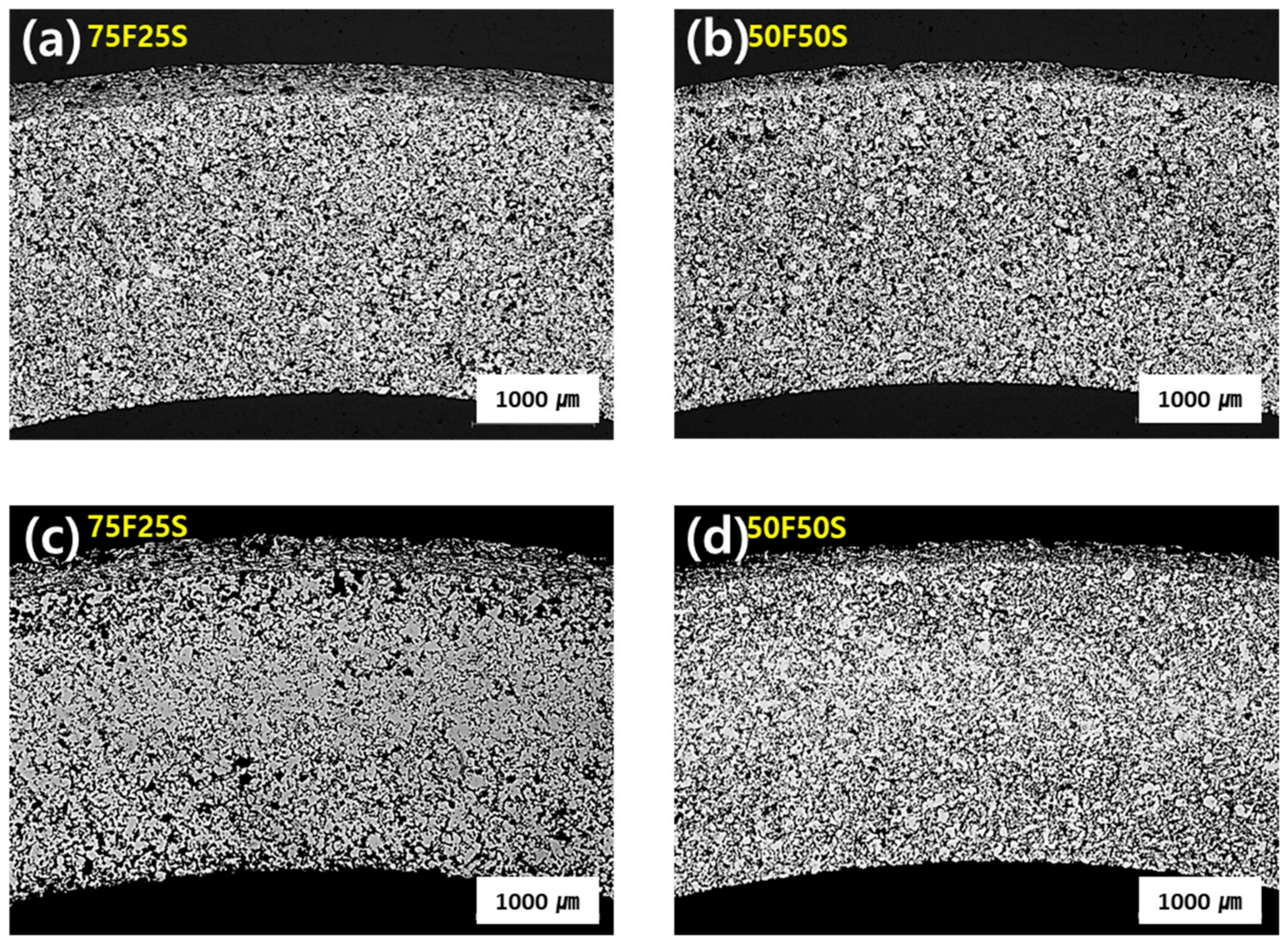
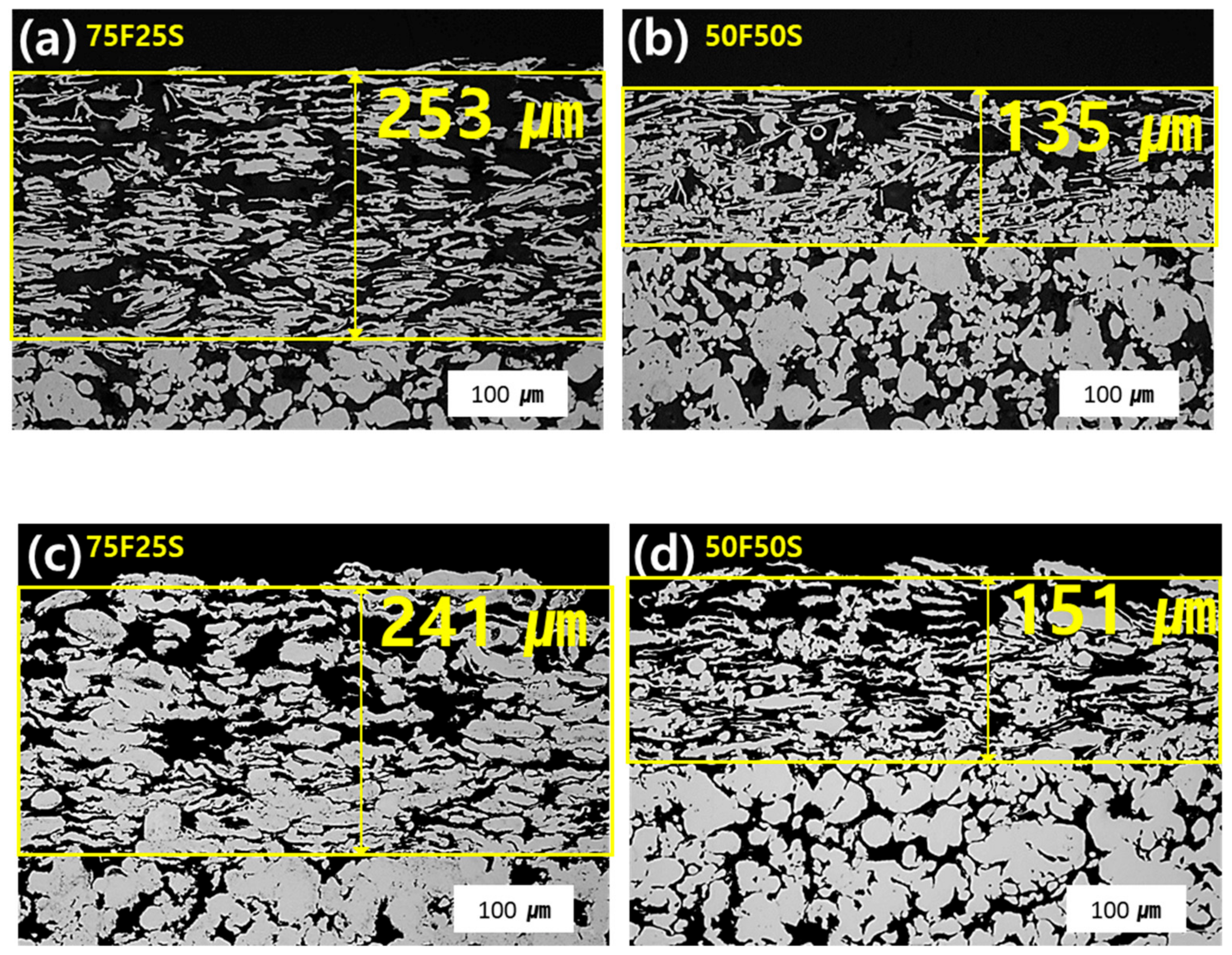
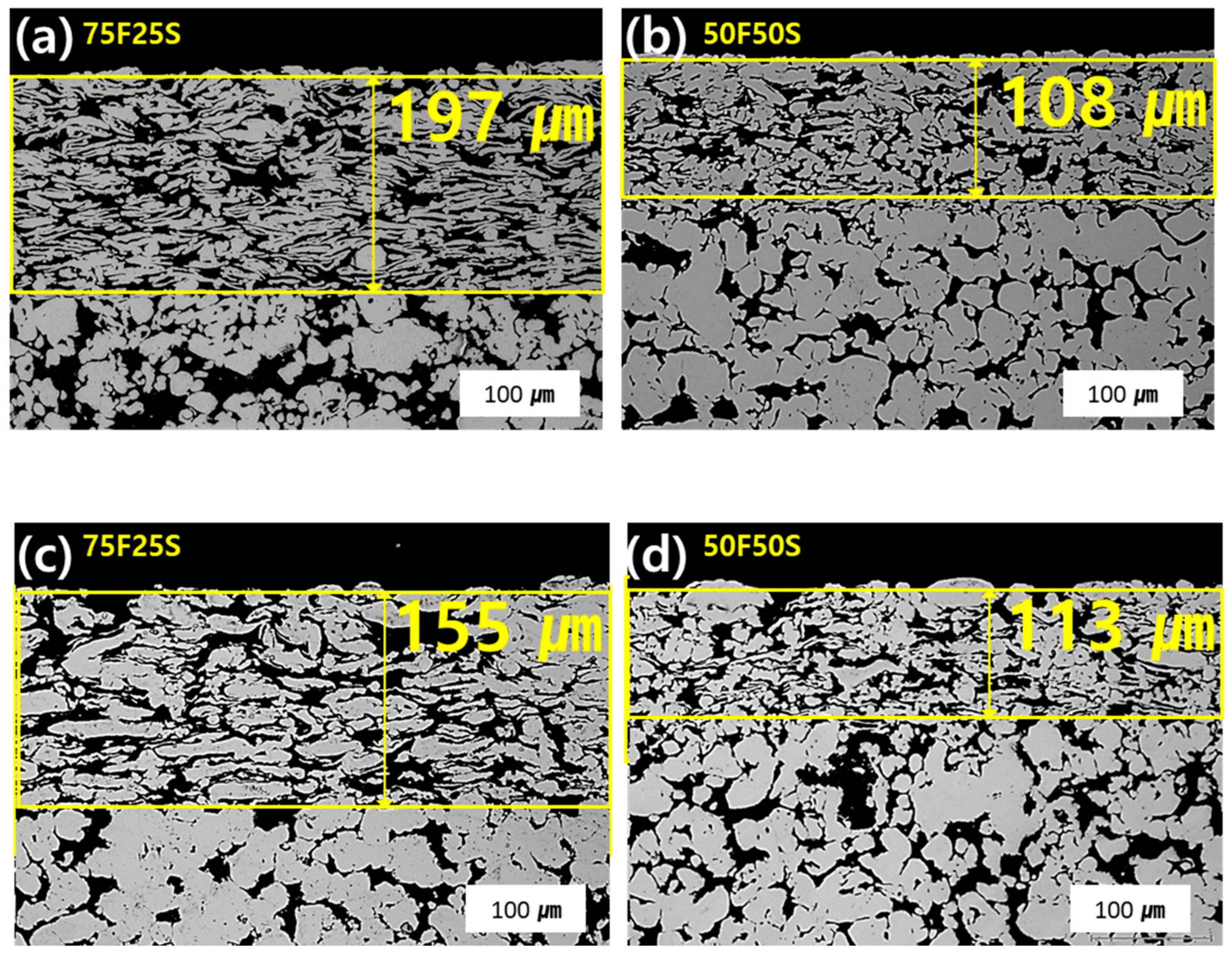
3.1. Microstructure

Figure 4 shows the cross-sectional structure of the prepared DLP powder filter from an optical microscope (OM) image. As can be seen from the figure, it was confirmed that the slurry prepared by mixing spherical powder and flake powder on a tube-type filter support, which is a coarse pore layer, was coated with a fine porous layer using a WPS process to finally manufacture a DLP powder filter with a complex flow path. Figure 4a,b show those prepared with flake powders with an average particle size of 37 μm, and Figure 4c,d show those with an average flake powder particle size of 60 μm. Regardless of the powder size and mixing ratio, it can be seen that the coating layer was applied without peeling on the tube-type filter support.
Figure 5a,b show the coating layers of the DLP powder filter made of flake powder with an average particle size of 37 μm, and Figure 5c,d show the coating layers of DLP powder filter made of flake powder with an average particle size of 60 μm. The coatings were performed under the same WPS process conditions. As can be seen from the figure, the thickness of the coating layer decreased from 253 to 135 μm and from 241 to 151 μm as the ratio of flake powder decreased. This is judged to reflect the higher tap density of mixed powders that contained a greater amount of relatively smaller and more spherical particles.
Further, when comparing the coating layers based on the size of the flake powder, it was observed that the pore volume within the coating layer increases as the flake powder size increases. Additionally, some flake-shaped powders may be oriented in an inclined position without being parallel to the cross-sectional direction of the surface of the rotating filter support.
Figure 6 shows the coated layer of the DLP powder filter sample after undergoing the rolling process for 5 min. As evident from the figure, when the rolling process was performed for 5 min, the thickness of the coating layer with an average powder size of 37 μm of flake powder decreased from 253 to 197 μm and from 135 to 108 μm in the case of 50F50S. In addition, it can be seen that for 75F25S with an average powder size of 60 μm of flake powder, the thickness of the coating layer decreased from 241 to 155 μm, and when it was 50F50S, it decreased from 151 to 113 μm. This indicates that the porous structure within the coated layer is oriented parallel to the cross-section of the filter, and the distribution of the pores is almost uniformly arranged.

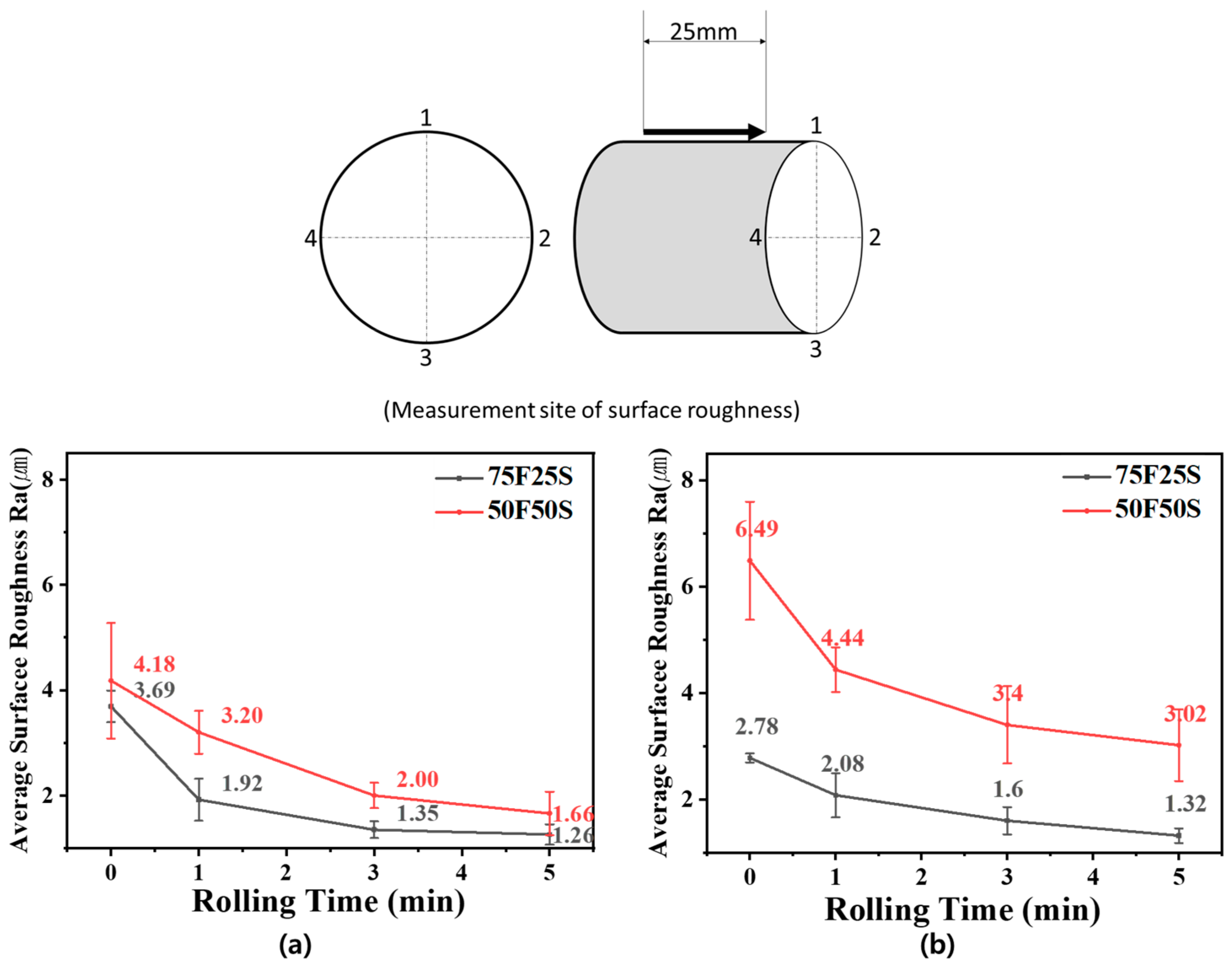
3.2. Surface Roughness

As shown in the figure below, the average value was calculated after measuring four parts (numbers 1~4) of the circumferential direction of the surface roughness area. Figure 7 shows the changes in surface roughness measured after the rolling process was conducted for 1 to 5 min. As can be observed from the microstructure of the coating layer, as the rolling process proceeded, the surface roughness of the coating layer with an average particle size of 37 μm for 75F25S decreased from 3.69 to 1.26 μm. For 50F50S, the surface roughness decreased from 4.18 to 1.66 μm. Additionally, it can be observed that for 75F25S with a coating layer with an average particle size of 60 μm, the surface roughness decreased from 2.78 to 1.32 μm. For 50F50S, the surface roughness decreased from 6.49 to 3.02 μm. The prediction is that the particle filtration efficiency will improve by reducing the surface roughness through the rolling process, which will result in a more uniform pore structure. This reduction in surface roughness is determined to improve gas permeability by reducing the porosity present inside and on the surface.

3.3. Porosity

Figure 8 shows the porosity measurement results from the image analysis system, illustrating the difference in contrast between the coating layers in Figure 5 and Figure 6. Comparing the initial porosity before the rolling process, the average porosity for an average flake powder particle size of 37 μm was 56.31%, while the average porosity was 43.765% for an average particle size of 60 μm, indicating the porosity was lower with larger particle size. And as the rolling process was performed, it can be seen that the uneven pore structure of the coating layer developed an orientation parallel to the filter cross-section, and the porosity decreased. Using powder with an average particle size of 37 μm, the porosity decreased by 29.62% at 75F25S and 26.19% at 50F50S. Similarly, when using powder with an average particle size of 60 μm, the porosity decreased by 35.45% at a mixing ratio of 75F25S and 27.95% at a mixing ratio of 50F50S. By using these reduced porosity values, it is inferred that effectively controlling the pores present in the interior and on the surface will influence the improvement of gas permeability [8,9].

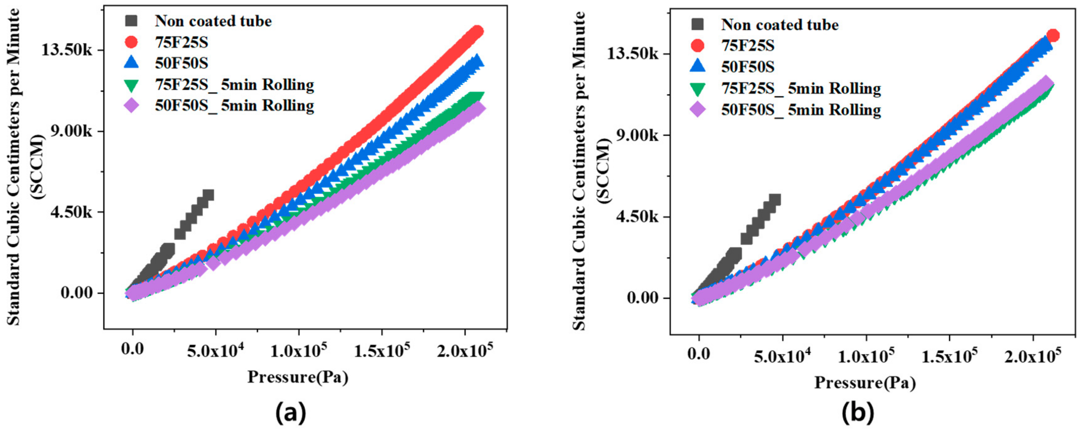
3.4. Gas Permeability

Figure 9 shows a graph measuring the gas permeability of the prepared DLP powder filter. Figure 9a shows the results for flake powder with an average particle size of 37 μm, while Figure 9b represents flake powder with an average particle size of 60 μm. Regardless of the average particle size and mixing ratio, the highest gas permeability was exhibited by the non-coated tube filter support. Also, the gas permeability was lower when using flake powder with an average particle size of 60 μm than when using flake powder with an average particle size of 37 μm. These results are similar to the porosity results in Figure 8, showing that the lower the porosity, the lower the gas permeability.
Additionally, regardless of the average particle size of the flake powder, the higher the proportion of spherical powder, the lower the gas permeability. When examining the effects of the rolling process, it was confirmed that gas permeability decreased when the rolling process was performed. This result is because the pressure drop increases with the complex pore structure, which decreases the gas permeability [13,16].

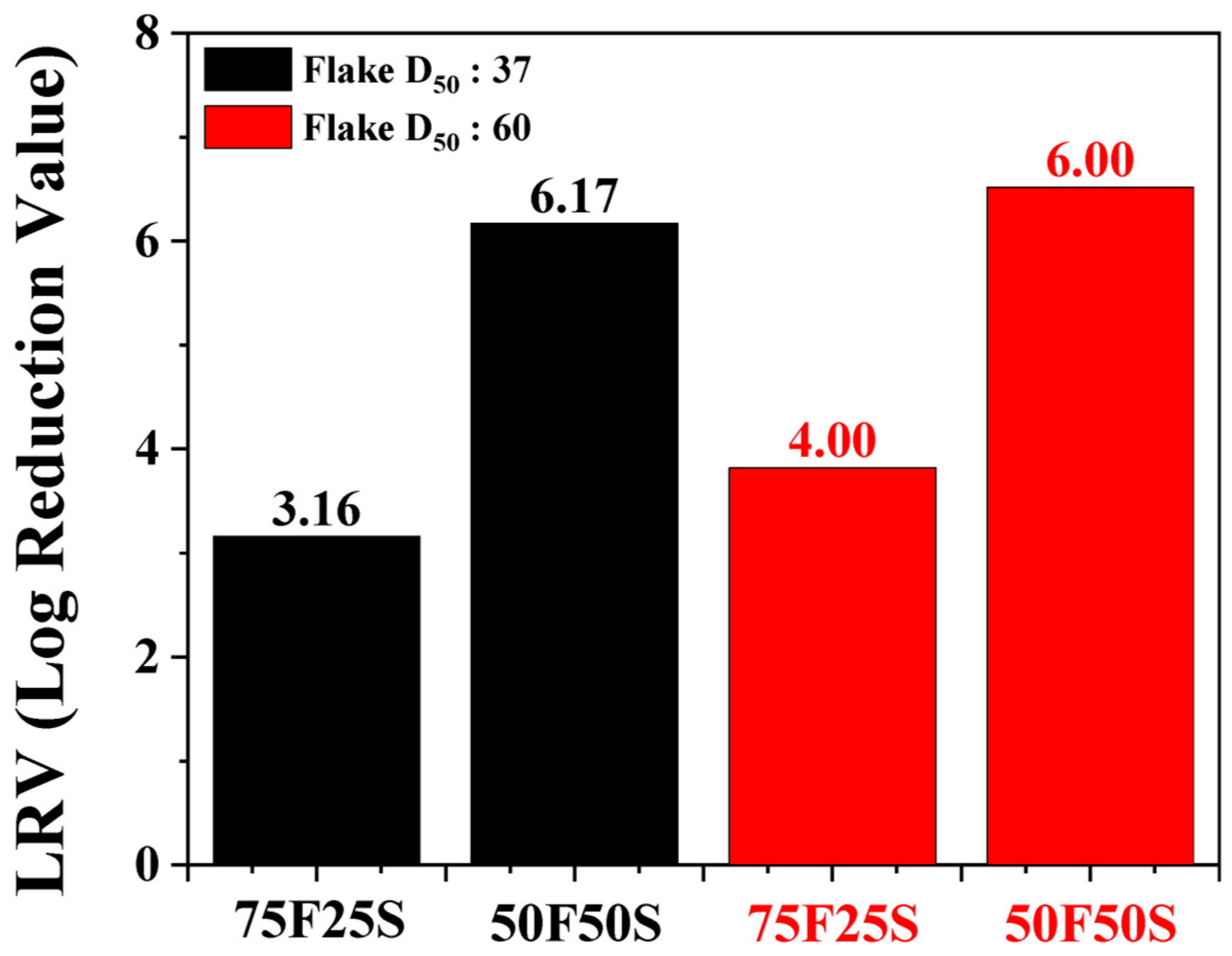
3.5. Filtration Efficiency

Figure 10 shows the measured particle filtration efficiency of the manufactured DLP powder filter. The particle filtration efficiency values are measured in terms of LRV (Log Reduction Value), and the calculation formula is shown below.
L R V = l o g A v e r a g e   c o n c e n t r a t i o n   o f   u p s t r e a m   p a r t i c l e s D o w n s t r e a m   a v e r a g e   c o n c e n t r a t i o n + 2 × d o w n s t r r e a m   s t a n d a r d   e r r o r
According to the measurement results, for the DLP powder filter with an average particle size of 37 μm, the LRV value was 3.16 for 75F25S and 6.17 for 50F50S, indicating that the LRV value increased as the content of spherical powder increased. Furthermore, for the DLP powder filter with an average particle size of 60 μm, the LRV was 3.82 for 75F25S and 6.52 for 50F50S, showing a trend similar to the previous results where the LRV value increased with an increase in spherical powder content. This is judged to occur because the smaller spherical particles fill more pore spaces and create longer particle flow paths, resulting in a higher filter efficiency. Generally, filters in the range of 4 to 5 LRV are used in bulk gas supply lines for semiconductors. The manufactured DLP powder filter has a filtration efficiency LRV of 6 (99.9999%), confirming its potential use as a filter for semiconductor processes.

4. Conclusions

In this study, we attempted to manufacture a metal powder filter with a double-layered pore structure that increases filtration efficiency through a complex flow path in the development of a gas filter used for high-purity gas supply in semiconductor manufacturing. We succeeded in manufacturing a SUS316L powder filter with a double-layer pore structure using the WPS process, which does not require a de-binding process compared to existing metal powder filter manufacturing methods and can be applied to various shapes.
The uniformity of the double-layered pore structure of metal powder filter was confirmed through microstructure observation, demonstrating the potential applicability of the WPS process in the manufacture of filters with complex pore structures.
The effects of the mixture ratio of flake and spherical powders and the rolling process on the microstructure and filter characteristics were investigated. Using the same WPS process conditions, it was observed that as the proportion of flake-shaped powder decreased, the thickness of the coating layer, coating amount, and porosity decreased. This is believed to be due to the higher tap density when the mixed powder contained relatively smaller spherical particles. Moreover, it was confirmed that as the size of flake powder increased to 60 μm, the pore volume inside the coating layer also increased. The measurement results of porosity showed that when the average particle size of the flake powder was 36 μm, the average porosity was 50%, whereas with an average particle size of 60 μm, the average porosity decreased to 40%. Additionally, some flake powders were oriented on the surface of rotating filter support in an inclined position in the cross-sectional direction. As the rolling process was performed, an uneven pore structure of the coating layer was oriented parallel to the filter section, resulting in a decrease in both coating thickness and porosity.
When investigating the characteristics of the manufactured filter, it was observed that regardless of the mixing ratio, gas permeability decreased with the rolling process. Furthermore, the particle filtration efficiency measurement results showed that as the ratio of spherical powder increased, the particle filtration efficiency was higher. This indicates that as the structure of the fine porous layer becomes more complex, the filter efficiency increases. Moreover, it was confirmed that the DLP powder filter manufactured with 50F50S powder exhibited a particle removal efficiency of LRV 6, indicating its potential usability as a filter for semiconductor processing applications.

Author Contributions

M.-J.L.: Investigation, writing—original draft. H.-J.K.: formal analysis, Investigation. D.-H.K.: formal analysis, investigation, funding acquisition. J.W.L.: Conceptualization, writing—review and editing, supervision. J.-Y.Y.: Methodology, writing—review and editing, supervision. All authors have read and agreed to the published version of the manuscript.

Funding

This work is supported by the Ministry of Trade, Industry & Energy (MOTIE) of the Republic of Korea (no. 20017434 and 20009937).

Data Availability Statement

The raw data supporting the conclusions of this article will be made available by the authors on request.

Conflicts of Interest

Author Du-Hong Kang was employed by the company ASFLOW Co., Ltd. The remaining authors declare that the research was conducted in the absence of any commercial or financial relationships that could be construed as a potential conflict of interest.

References

  1. Shim, J.D.; Byun, J.Y. Production Processes of Porous Metals and Their Applications. Korean J. Mater. Res. 2015, 25, 155–164. [Google Scholar] [CrossRef]
  2. Costanza, G.; Solaiyappan, D.; Tata, M.E. Properties, Applications and Recent Developments of Cellular Solid Materials: A Review. Materials 2023, 16, 7076. [Google Scholar] [CrossRef] [PubMed]
  3. Behymer, N.; Morsi, K. Closed-Cell Metallic Foams Produced via Powder Metallurgy. Metals 2023, 13, 959–988. [Google Scholar] [CrossRef]
  4. Skibinski, J.; Cwieka, K.; Kowalkowski, T.; Wysocki, B.; Wejrzanowski, T.; Kurzydlowski, K.J. The influence of pore size variation on the pressure drop in open-cell foams. Mater. Des. 2015, 87, 650–655. [Google Scholar] [CrossRef]
  5. Ashby, M.F.; Evans, A.; Fleck, N.A.; Gibson, L.J.; Hutchinson, J.W.; Wadley, H.N.G.; Delale, F. Metal foams: A design guide. Appl. Mech. Rev. 2001, 54, B105–B106. [Google Scholar] [CrossRef]
  6. Heikkinen, M.S.; Harley, N.H. Experimental investigation of sintered porous metal filters. J. Aerosol Sci. 2000, 31, 721–738. [Google Scholar] [CrossRef]
  7. Park, J.E.; Hwang, W.; Lim, M.S.; Kim, S.; Ahn, C.Y.; Kim, O.H.; Shim, J.G.; Lee, D.W.; Lee, J.H.; Cho, Y.H.; et al. Achieving breakthrough performance caused by optimized metal foam flow field in fuel cells. Int. J. Hydrogen Energy 2019, 44, 22074–22084. [Google Scholar] [CrossRef]
  8. Lee, J.H.; Kim, G.M.; Jo, S.T.; Kim, D.W. A study on the surface pre-treatment of the porous metal support for the hydrogen separation membrane. In Proceedings of the Korean Institute of Surface Engineering Conference the Korean Institute of Surface Engineering, Seoul, Republic of Korea, 20–21 November 2014; pp. 156–157. [Google Scholar]
  9. Hwang, K.R.; Oh, D.K.; Lee, S.W.; Park, J.S.; Song, M.H.; Rhee, W.H. Porous stainless steel support for hydrogen separation Pd membrane; fabrication by metal injection molding and simple surface modification. Int. J. Hydrogen Energy 2017, 42, 14583–14592. [Google Scholar] [CrossRef]
  10. Lefebvre, L.P.; Banhart, J.; Dunand, D.C. Porous metals and metallic foams: Current status and recent developments. Adv. Eng. Mater. 2008, 10, 775–787. [Google Scholar] [CrossRef]
  11. Gallucci, F.; Fernandez, E.; Corengia, P.; Annaland, M.V.S. Recent advances on membranes and membrane reactors for hydrogen production. Chem. Eng. Sci. 2013, 92, 40–66. [Google Scholar] [CrossRef]
  12. Lee, M.S.; Lee, K.H.; Lee, Y.S.; Chung, K.Y. A Study on the Validity of the Metal Filter Application in MBR Process. Membr. Soc. Korea 2022, 32, 66–73. [Google Scholar] [CrossRef]
  13. Jeon, D.H.; Greenway, S.; Shimpalee Van Zee, J.W. The effect of serpentine flow-field designs on PEM fuel cell performance. Int. J. Hydrogen Energy 2008, 33, 1052–1066. [Google Scholar] [CrossRef]
  14. Kumar, A.; Reddy, R.G. Materials and design development for bipolar/end plates in fuel cells. J. Power Sources 2004, 129, 62–67. [Google Scholar] [CrossRef]
  15. Jo, A.; Ju, H. Numerical study on applicability of metal foam as flow distributor in polymer electrolyte fuel cells (PEFCs). Int. J. Hydrogen Energy 2018, 43, 14012–14026. [Google Scholar] [CrossRef]
  16. Kozakai, M.; Date, K.; Tabe, Y.; Chikahisa, T. Improving gas diffusivity with bi-porous flow-field in polymer electrolyte membrane fuel cells. Int. J. Hydrogen Energy 2016, 41, 13180–13189. [Google Scholar] [CrossRef]
  17. Seong, G.H. Study on Characteristics and Application of High-Flow Metal Membrane with High Corrosion Resistance. Ph.D. Thesis, Hanyang University, Seoul, Republic of Korea, 2018. Available online: https://repository.hanyang.ac.kr/handle/20.500.11754/69007 (accessed on 3 December 2021).
  18. Cho, Y.B.; Jeon, K.S.; Her, J.Y.; You, K.H. Study on improvement of efficiency of gas filter at the natural gas valve station. Korean Inst. Gas 1998, 2, 47–52. [Google Scholar]
  19. Ou, Q.; Maricq, M.M.; Pakko, J.; Chanko, T.B.; Pui, D.Y. Design and evaluation of a sintered metal fiber filter for gasoline direct injection engine exhaust aftertreatment. J. Aerosol Sci. 2019, 133, 12–23. [Google Scholar] [CrossRef]
  20. Banhart, J. Manufacturing routes for metallic foams. JOM 2000, 52, 22–27. [Google Scholar] [CrossRef]
  21. Banhart, J. Manufacture, Characterisation and Application of Cellular Metals and Metal Foams. Prog. Mater. Sci. 2001, 46, 559–632. [Google Scholar] [CrossRef]
  22. Wang, N.; Chen, X.; Li, Y.; Liu, Z.; Zhao, Z.; Cheng, Y.; Liu, Y.; Zhang, H. The cell size reduction of aluminum foam with dynamic gas injection based on the improved foamable melt. Colloids Surf. A Physicochem. Eng. Asp. 2017, 527, 123–131. [Google Scholar] [CrossRef]
  23. Choi, J.H.; Yang, S.S.; Kim, Y.D.; Yun, J.Y. The Effect of Binder Content for the Pore Properties of Fe Foam Fabricated by Slurry Coating Process. J. Korea Powd. Met. Inst. 2013, 20, 266–270. [Google Scholar] [CrossRef]
  24. Jeong, H.Y.; Kim, T.Y.; Im, E.M.; Lim, D.H. Optimum Synthesis Conditions of Coating Slurry for Metallic Structured De-NO x Catalyst by Coating Process on Ship Exhaust Gas. Clean Technol. 2018, 24, 127–134. [Google Scholar] [CrossRef]
  25. Mondal, D.P.; Jain, H.; Das, S.; Jha, A.K. Stainless steel foams made through powder metallurgy route using NH4HCO3 as space holder. Mater. Des. 2015, 88, 430–437. [Google Scholar] [CrossRef]
  26. Jain, H.; Kumar, R.; Gupta, G.; Mondal, D.P. Microstructure, mechanical and EMI shielding performance in open cell austenitic stainless steel foam made through PU foam template. Mater. Chem. Phys. 2020, 241, 122–273. [Google Scholar] [CrossRef]
  27. Essa, K.; Jamshidi, P.; Zou, J.; Attallah, M.M.; Hassanin, H. Porosity control in 316L stainless steel using cold and hot isostatic pressing. Mater. Des. 2018, 138, 21–29. [Google Scholar] [CrossRef]
  28. Li, R.; Liu, J.; Shi, Y.; Du, M.; Xie, Z. 316L stainless steel with gradient porosity fabricated by selective laser melting. J. Mater. Eng. Perform. 2010, 19, 666–671. [Google Scholar] [CrossRef]
  29. Meenashisundaram, G.K.; Xu, Z.; Nai, M.L.S.; Lu, S.; Ten, J.S.; Wei, J. Binder jetting additive manufacturing of high porosity 316L stainless steel metal foams. Materials 2020, 13, 3744. [Google Scholar] [CrossRef] [PubMed]
  30. Lee, M.J.; Kim, H.J.; Park, M.H.; Yun, J.Y. Fabrication and Pore Properties of SUS316L Membrane with Double-Layered Pore Structures by Wet Powder Spraying. Arch. Metall. Mater. 2022, 67, 1531–1534. [Google Scholar] [CrossRef]
  31. Lee, M.J.; Yi, Y.J.; Kim, H.J.; Park, M.; Lee, J.; Yun, J.Y. Microstructure and Pore characteristics of a sus316L Gas filter fabricated by Wet Powder Spraying. Arch. Metall. Mater. 2022, 67, 1547–1550. [Google Scholar] [CrossRef]
  32. Lee, C.H.; Choi, J.H.; Kim, M.S.; Seo, B.H.; Kang, C.H.; Lim, D.H. An Optimization Study on a Low-temperature De-NOx Catalyst Coated on Metallic Monolith for Steel Plant Applications. Clean Technol. 2021, 27, 332–340. [Google Scholar] [CrossRef]
  33. Wolff, M.; Schwiers, A.; Wilkner, K.; Sebold, D.; Menzler, N.H. Wet powder spraying—A versatile and highly effective technique for the application of spinel-type protective coatings on SOC interconnects. J. Power Sources 2024, 592, 233931. [Google Scholar] [CrossRef]
  34. Marie, A.; Tourbin, M.; Robisson, A.C.; Ablitzer, C.; Frances, C. Wet size measurements for the evaluation of the deagglomeration behaviour of spray-dried alumina powders in suspension. Ceram. Int. 2022, 48, 7926–7936. [Google Scholar] [CrossRef]
  35. Ruder, A.; Buchkremer, H.P.; Jansen, H.; Mallener, W.; Stöver, D. Wet powder spraying—A process for the production of coatings. Surf. Coat. Technol. 1992, 53, 71–74. [Google Scholar] [CrossRef]
  36. Zhao, L.; Bram, M.; Buchkremer, H.P.; Stöver, D.; Li, Z. Preparation of TiO2 composite microfiltration membranes by the wet powder spraying method. J. Membr. Sci. 2004, 244, 107–115. [Google Scholar] [CrossRef]
  37. Smith, B.H.; Szyniszewski, S.; Hajjar, J.F.; Schafer, B.W.; Arwade, S.R. Steel foam for structures: A review of applications, manufacturing and material properties. J. Constr. Steel Res. 2012, 71, 1–10. [Google Scholar] [CrossRef]
  38. Park, M.H.; Lee, S.H.; Lee, K.H.; Kim, J.G. Filter for Integrated Gas Supply System Module and Manufacturing Method of the Same. K.R. Patent No. 20210026348A, 8 August 2021. [Google Scholar]
  39. Yun, J.Y.; Park, M.H.; Lee, K.H.; Kang, D.H. Filter Comprising a Coating Layer of Flake-Like Powders and a Preparation Method Thereof. U.S. Patent No. 11,660,556, 30 May 2023. [Google Scholar]
  40. Yun, S.J.; Kim, H.J.; Seo, E.C.; Kim, M.J.; Park, M.H.; Lee, J.W.; Yun, J.Y. Fabrication of a Plate-type Porous stainless steel 316l Powder Filter with different Pore structures without use of a binder. Arch. Metall. Mater. 2024, 69, 497–500. [Google Scholar] [CrossRef]
Figure 1. SEM images and particle size distribution of (a) the spherical shape, (b) the flake shape powder, and (c) the flake shape powder used in this study.
Metals 14 00665 g001
Figure 2. Schematic diagram of the process for fabricating the DLP powder filter samples.
Metals 14 00665 g002
Figure 3. Schematic diagram of the sintering cycle used to sinter the DLP powder filter samples.
Metals 14 00665 g003
Figure 4. Cross-sectional OM image of DLP powder filters fabricated by WPS process with different average particle sizes: (a,b) 37 μm flake, (c,d) 60 μm flake.
Metals 14 00665 g004
Figure 5. OM image of coating layer fabricated by WPS process with different average particle sizes: (a,b) 37 μm flake, (c,d) 60 μm flake.
Metals 14 00665 g005
Figure 6. OM image of coating layer after 5 min of rolling process with different average particle sizes: (a,b) 37 μm flake, (c,d) 60 μm flake.
Metals 14 00665 g006
Figure 7. Surface roughness of the DLP powder filter samples according to average particle size: (a) 37 μm flake, (b) 60 μm flake.
Metals 14 00665 g007
Figure 8. Porosity of the DLP powder filter samples according to average particle size: (a) 37 μm flake, (b) 60 μm flake.
Metals 14 00665 g008
Figure 9. Gas permeability of the DLP powder filter based on powder mixing ratio and rolling effect: (a) 37 μm flake, (b) 60 μm flake.
Metals 14 00665 g009
Figure 10. Filtration efficiency of the DLP powder filter samples according to average particle size difference.
Metals 14 00665 g010
Table 1. The chemical composition of SUS316L stainless steel powders (wt.%).
ShapeElement (wt.%)Mixing Ratio (%)
CrNiMoFe75F25S50F50S
Spherical16~1812~162~3Balance2550
Flake16~18.510~142~3Balance7550
Table 2. WPS experiments conditions.
Tube-type filter supportExterior diameter (30 mm), Inner diameter (25.5 mm), Length (70 mm)
Spray nozzle typeVortex (Atomax BN160)
Binder solutionMethycellulose 4 wt.% + Distilled water 96 wt.%
SlurryPowder 40 wt.% + Binder solution 20 wt.% + Ethanol 40 wt.%
Slurry flow rate (mL/min)200
Air pressure (MPa)0.25
Distance between nozzle tip and tube (mm)130
Width of movement (mm)523
Nozzle moving speed (mm/s)87.17
Disclaimer/Publisher’s Note: The statements, opinions and data contained in all publications are solely those of the individual author(s) and contributor(s) and not of MDPI and/or the editor(s). MDPI and/or the editor(s) disclaim responsibility for any injury to people or property resulting from any ideas, methods, instructions or products referred to in the content.

