Article

A Study on the Effects of Welding Deformation According to Weld Sequence in Overlay-Welded Structures

1
Department of Railroad Operation Systems Engineering, Korea National University of Transportation, Uiwang 16106, Republic of Korea
2
Department of Smart Ocean Mobility Engineering, Changwon National University, Changwon 51140, Republic of Korea
*
Author to whom correspondence should be addressed.
Metals 2024, 14(6), 684; https://doi.org/10.3390/met14060684
Submission received: 20 May 2024 / Revised: 4 June 2024 / Accepted: 6 June 2024 / Published: 9 June 2024

Abstract

:
In this study, thermal elasto-plastic finite element analysis was conducted to derive the optimal welding sequence to minimize overlay welding deformation on the water wall panels of an SRF (solid refuse fuel) boiler. The water wall panels of an SRF boiler are exposed to high temperatures and corrosive environments, making overlay welding essential. However, because the length of the water wall panels and tubes exceeds 7 m, significant deformation occurs after overlay welding. Additionally, due to the large size of the water wall panels, full-size thermal elasto-plastic analysis requires huge computational costs. Therefore, in this study, the effects of welding sequence on overlay welding deformation were first investigated for a reduced model to derive the optimal welding sequence. Subsequently, an analysis model for the full-size pipe panels was established to compare and analyze the conventional welding sequence with the optimal welding sequence, thereby verifying the validity of the study. According to the welding sequence derived from the reduced model, welding deformation in the full-size model was significantly reduced compared to the conventional sequence. This reduction in deformation was discussed by analyzing the deformation behavior of the structure at each stage of the overlay welding process.

1. Introduction

Typically, welding deformation causes numerous problems. The deterioration of structures due to buckling, fatigue, and ultimate strength degradation results in a reduction in their lifespan. This results in severe structural damage during welding operations and reduces quality. The process of removing welding deformation also leads to a loss of productivity. Such welding deformation occurs due to localized heat applied during welding, which creates a non-uniform temperature distribution in the thickness and width directions of the plate. Consequently, permanent plastic deformation remains due to thermal stress. Therefore, welding deformation is a three-dimensional transient thermal elasto-plastic analysis problem that requires modeling thermal conductivity and elasto-plastic structural analysis over time.
To predict the amount of welding deformation, many numerical methods have been proposed [1]. The thermal elasto-plastic analysis method simulates all physical phenomena related to the welding process as closely as possible to reality and is mainly applied for precise welding process simulations to understand thermal, structural, and metallurgical phenomena. However, this method requires significant computational time [1,2]. Deng et al. [3] performed a 3D thermal elasto-plastic finite element analysis to determine the welding deformation of fillet-welded joints and compared the results with experimental data. The welding deformation finite element analysis involved two steps: first, a heat conduction analysis was performed, followed by a mechanical structural analysis based on the temperature history obtained from the heat conduction analysis. Obeid et al. presented a nonlinear heat-transfer and mechanical finite element (FE) analysis of a two-pass welding process of two segments of lined pipe made of SUS304 stainless steel liner and C-Mn steel pipe [4]. Numerous studies have focused on enhancing the efficiency of thermal elasto-plastic finite element analysis in welding applications. One approach involves using 3D/shell elements to minimize the number of nodes, which, in turn, reduces simulation time [5,6,7]. Murakawa et al. [8] introduced an iterative substructure method that segments the model into highly nonlinear regions near the weld pool and less nonlinear regions, thereby decreasing simulation time [9,10]. Additionally, recent advancements have seen the adoption of parallel computation techniques utilizing graphical processing units (GPU) to significantly boost the speed of welding deformation predictions [11,12,13,14].
On the other hand, simplified methods such as the equivalent load method (ELM) and the equivalent strain method (ESM) can reduce analysis time but are less accurate compared to thermal elasto-plastic analysis. The equivalent load method extracts the characteristics of welding deformation and converts the causes of deformation into equivalent loads. This method is used to estimate the welding deformation of complex structures in a very short time. Equivalent loads for welding deformation can be estimated through experiments [15,16,17,18] or the inherent strain method (ISM) [19]. The disadvantage of using equivalent load analysis for welding deformation prediction is that it cannot consider welding residual stress. Therefore, recent studies have focused on predicting welding deformation and residual stress using the equivalent strain method. Kang et al. [20] applied the equivalent load method based on inherent strain to calculate the deformation of friction-stir-welded (FSW) electric vehicle battery housings, reducing computation time to 1/30 of the thermal elasto-plastic analysis method and validating the approach by comparing it with experimental results. Kim et al. [21] applied the equivalent strain method to ship block welding experiments, comparing the results with elasto-plastic analysis and equivalent load analysis results. Inherent strain models using solid-spring models with two-dimensional constraints and cubic elements with three-dimensional constraints [22,23] have been proposed to predict equivalent strain. Additionally, Lee et al. [24] developed an FE modeling method for the efficient prediction of welding angular distortion. In the FE formulation, the force matrix is explicitly derived to transform scalar input variables considering mesh size. Rong et al. [25] performed laser butt welding experiments to observe the characteristics of keyholes and weld pools. Using high-speed imaging and image processing, the geometries of keyholes and weld pools were extracted. A double cylindrical heat source model considering keyhole angle and diameter was derived and validated using the measured weld pool geometries.
When it comes to optimizing the welding sequence and accurately predicting the final welding deformation, thermal elasto-plastic analysis is limited by the lengthy analysis time. Therefore, many researchers have used simplified analysis models or performed case studies on candidate welding sequences using thermal elasto-plastic analysis to optimize the welding sequence. Gannon et al. [26] analyzed the effects of welding sequence on flat-bar stiffened plates through sequentially coupled thermal and structural finite element analyses to examine residual stress and welding deformation. They utilized an element birth and death technique to model the addition of weld metal to the workpiece. The resulting FE model was validated against experimental data reported by Deng et al. [3], and four different welding sequences were analyzed for their effects on the residual stresses and deformations of flat-bar stiffened plates. In the shipbuilding industry, Kang et al. [27] optimized welding sequences for block assemblies with a focus on productivity and workability. L Romanin et al. [28] tackled large welded structures by dividing them into smaller local structures, calculating them independently, and then using the equivalent load method to determine overall welding deformation. Tabar et al. [29] and Heung et al. [30] employed genetic algorithms to optimize spot-welding sequences. Kadivar et al. [31] used thermal elasto-plastic analysis for a two-dimensional finite element model, comparing the simulation results with the analysis results, and also utilized a genetic algorithm for sequence optimization. Romero-Hdz et al. [32] applied artificial intelligence techniques for optimizing welding sequences, though this approach lacked experimental validation and did not consider factors like residual stress and temperature. Ha [33] used the elasto-plastic strain-boundary method to derive an optimal welding sequence, reducing calculation time with a simplified method but achieving only qualitative predictions. In addition, there have been recent publications of case studies using thermal elasto-plastic finite element analysis to derive optimal welding sequences to minimize welding deformation for joints used in sealing [34], stiffened plates [35,36], and copper alloy plates [37]. With the recent advancements in computing, there are also active studies on developing methodologies that incorporate artificial intelligence to optimize welding sequences using training models on results obtained from thermal elasto-plastic finite element analysis [38,39].
In this study, a thermal elasto-plastic welding analysis was performed to minimize overlay welding deformation on the water wall panels of an SRF boiler. The effects of welding sequence on overlay welding deformation were investigated for smaller-sized pipe panels, and then, the optimal welding sequence was determined. Subsequently, an analysis model for full-sized pipe panels was established to compare and analyze the conventional welding sequence with the optimal welding sequence, thereby verifying the validity of the study.

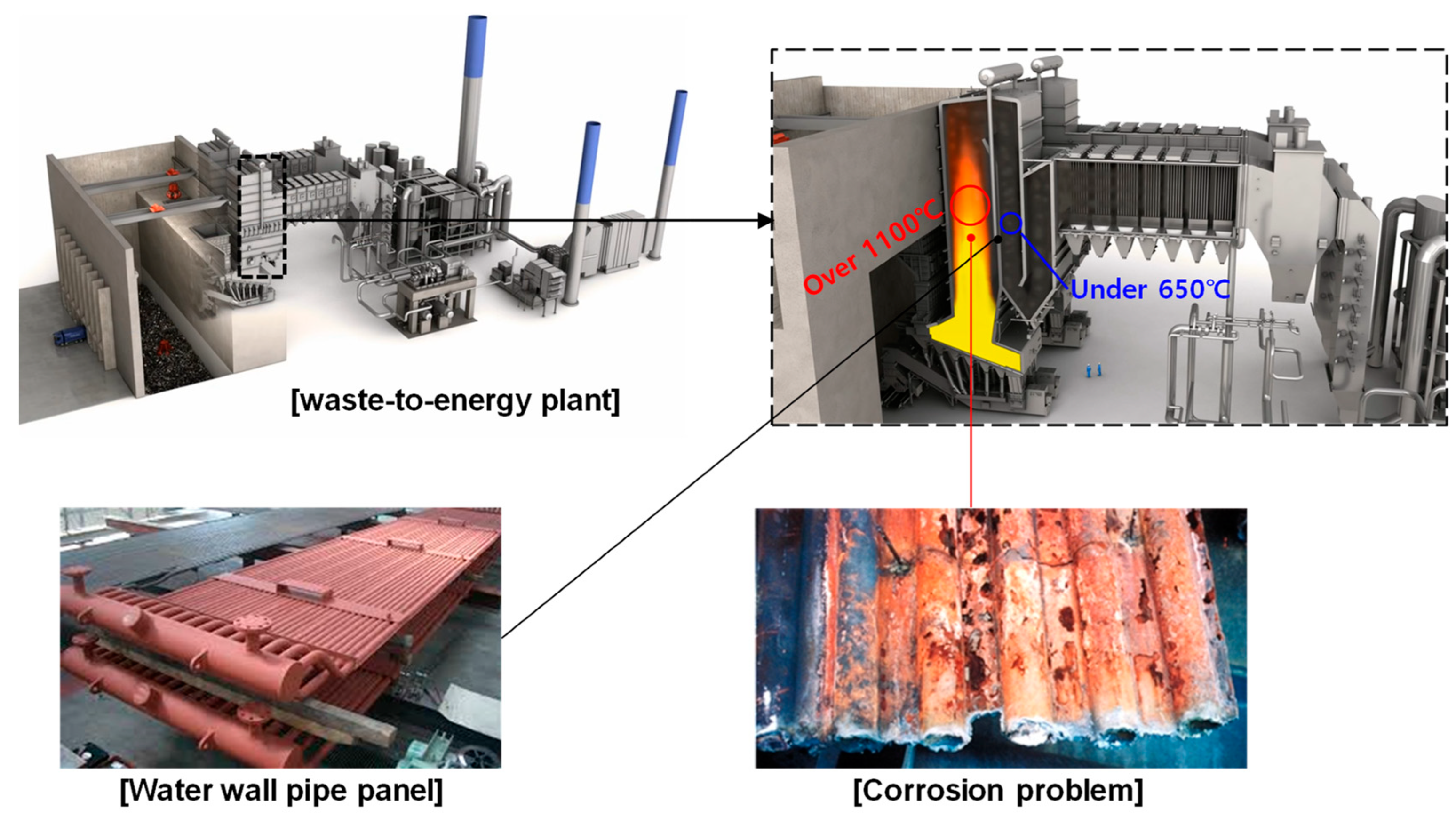
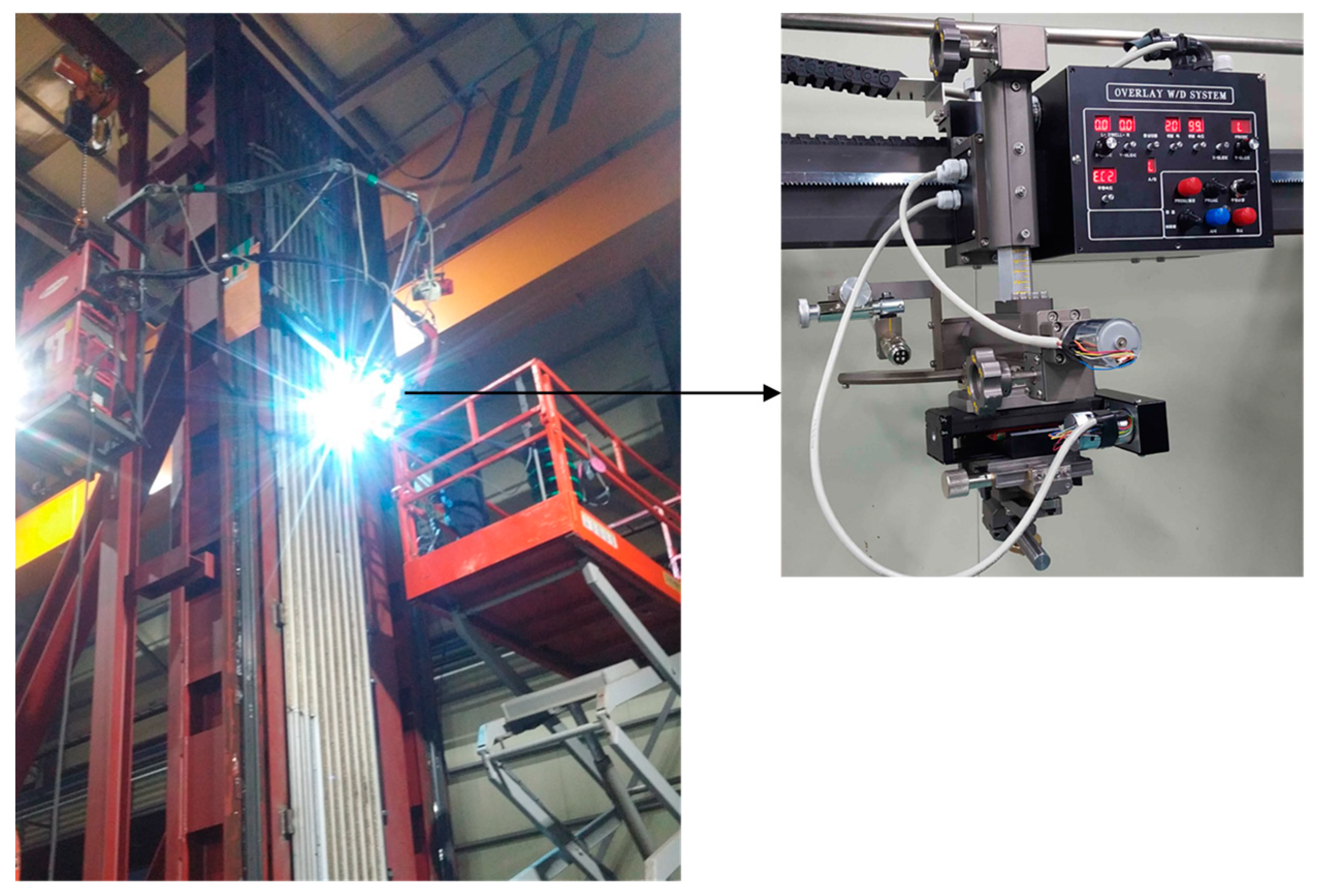
2. Overlay Welding Process

Overlay welding, also known as cladding, hardfacing, weld cladding, or weld overlay cladding, is a process where one or more metals are joined together via welding to the surface of a base metal as a layer. This is primarily carried out to improve the material by adding a corrosion-resistant or hardfacing layer. Surfaces prepared in this way can be highly customized by layering and alloying multiple different materials together. To reduce material costs, expensive Inconel material is overlaid onto low-cost steel pipes. Manufacturing a pipe panel using 100% Inconel is very expensive, and Inconel also has low formability. The overlay welding method is economical because it minimizes the consumption of expensive material by welding Inconel onto steel. This reduces production costs by 60% while ensuring product quality [40,41,42].
As shown in Figure 1, the water wall panels of an SRF boiler are exposed to high temperatures and corrosive environments, making overlay welding essential. However, since the length of the water wall panels and tubes exceeds 7 m, significant deformation occurs after overlay welding.
The overlay welding process for water wall panels is conducted from the top to the bottom using automated welding equipment after the structure has been erected vertically, as shown in Figure 2. In Figure 2, the operator is tasked with inspecting the weld to ascertain the quality of the overlay weld. Welding deformation occurs due to temperature gradients and constraints after pipe panel overlay welding. Figure 3 shows an example of a pipe panel that has become deformed after overlay welding.

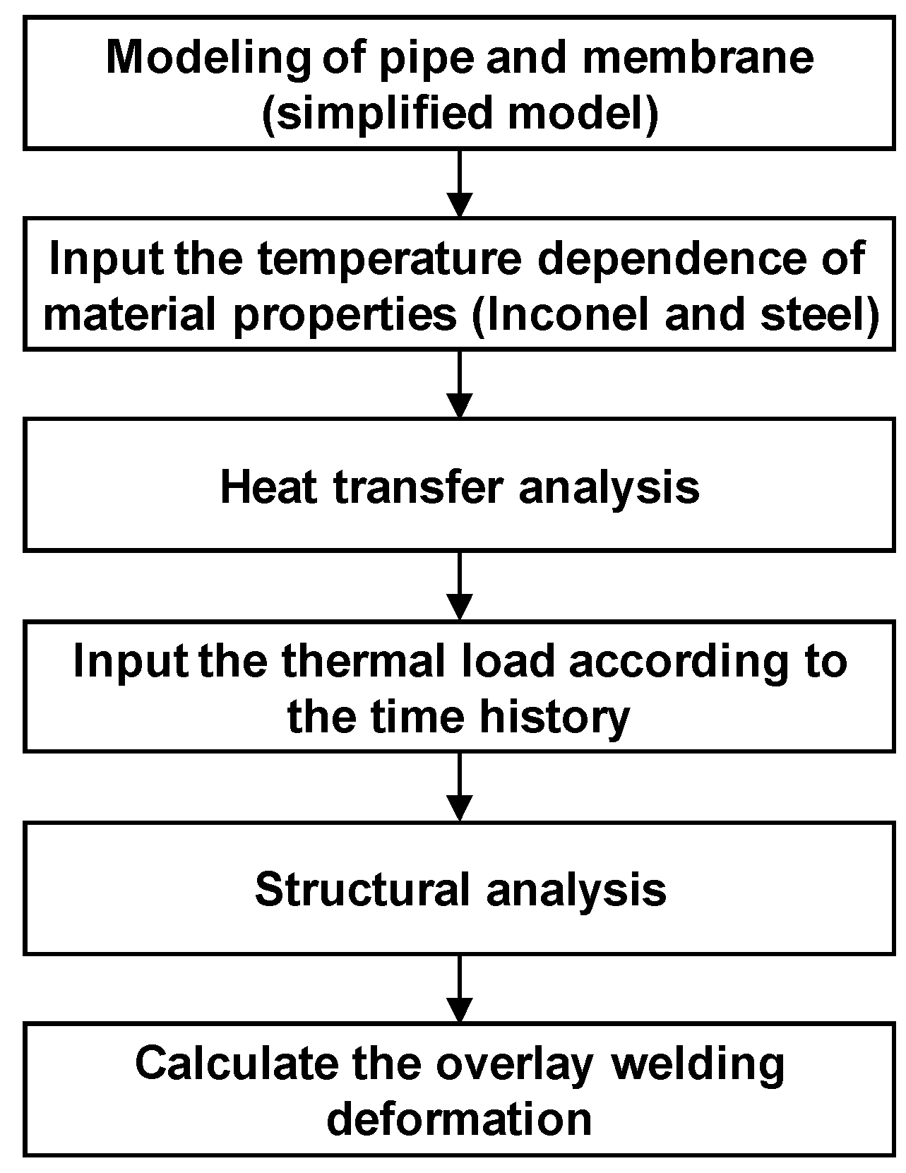
3. Overlay Welding Thermal Elasto-Plastic Analysis
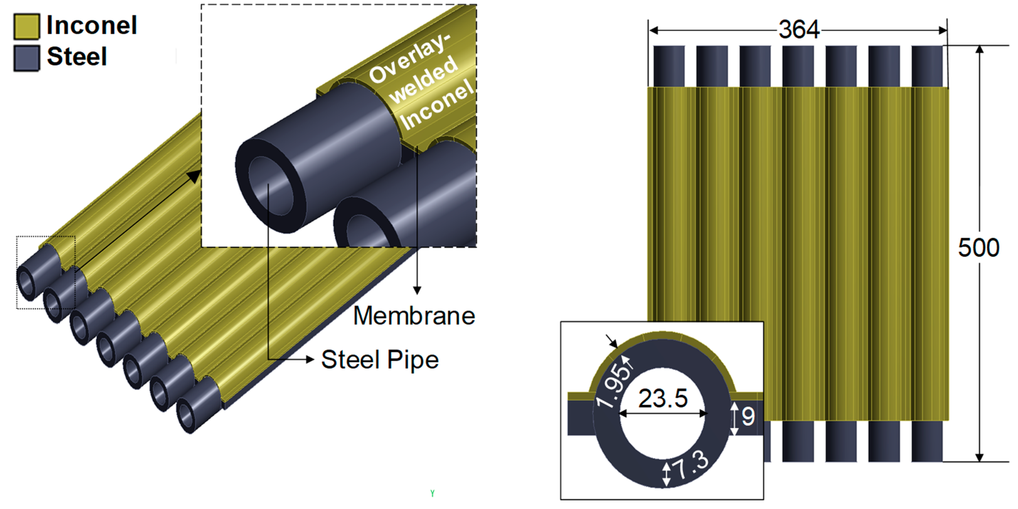
In this study, a thermal elasto-plastic analysis was performed to minimize the deformation of overlay-welded pipe panels. For actual structures, the size is so large that there are issues with long analysis times or non-convergence of the solution. Therefore, the size of the structure was reduced, and the deformation results according to the welding sequence and coolant temperature were compared. Details of the process of the thermal elasto-plastic welding analysis are sequentially explained in the following sections.

3.1. Modeling

A three-dimensional numerical model was constructed for the thermal elasto-plastic analysis of overlay welding using ANSYS Mechanical 19 (finite element analysis software). The finite element analysis model of the pipe panel for thermal elasto-plastic overlay welding consists of seven pipes. The membrane connects the pipes together. As shown in Figure 4, the analytical model consists of steel pipes, a steel membrane, and Inconel material to be overlay-welded. In this study, the grades of the materials used are SS 400 and Inconel 718, respectively. The size of the analytical model is 364 mm in width and 500 mm in height. The internal diameter of the steel pipe is 23.5 mm, while its external diameter is 30.8 mm. The Inconel material is overlay-welded to a thickness of 1.95 mm, and the membrane is 9 mm thick.
The temperature-dependent material properties of SS 400 and Inconel 718 are crucial for conducting thermal elasto-plastic analysis of pipe panel overlay welding. During the overlay welding process, the temperature of Inconel can rise to about 1400 °C, causing changes in the material properties with temperature. This is particularly significant in welding analysis, where temperature changes are more pronounced. Therefore, it is essential to perform thermal elasto-plastic analysis considering these temperature-dependent material properties. For this analysis, properties such as density, thermal conductivity, specific heat, thermal expansion coefficient, elastic modulus, yield stress, and Poisson’s ratio are required. The temperature-dependent material property values used in this study are based on the existing literature and shown in Figure 5 and Figure 6 [43,44].
In this study, heat transfer analysis is carried out and the temperature data of every step are saved. Thermal elasto-plastic analysis is implemented using the saved temperature data. Thermal deformation and residual stresses occur due to the operational temperature fields. The thermal strain is given by Equation (1) [45].
ε t h = α × Δ T
where ε t h is the thermal strain, α is the thermal expansion coefficient, and Δ T is the temperature difference. The reference temperature is assumed to be 22 °C. Thermal strain depends on the thermal expansion coefficient and temperature gradient. The temperature history significantly affects the value and distribution of residual stress. Figure 7 shows a flow chart for the overall overlay weld thermal elasto-plastic analysis.
As shown in Figure 8, the analytical model uses a 5 mm hexahedral element for meshing. The total number of elements is 52,293, and the total number of nodes is 426,641.

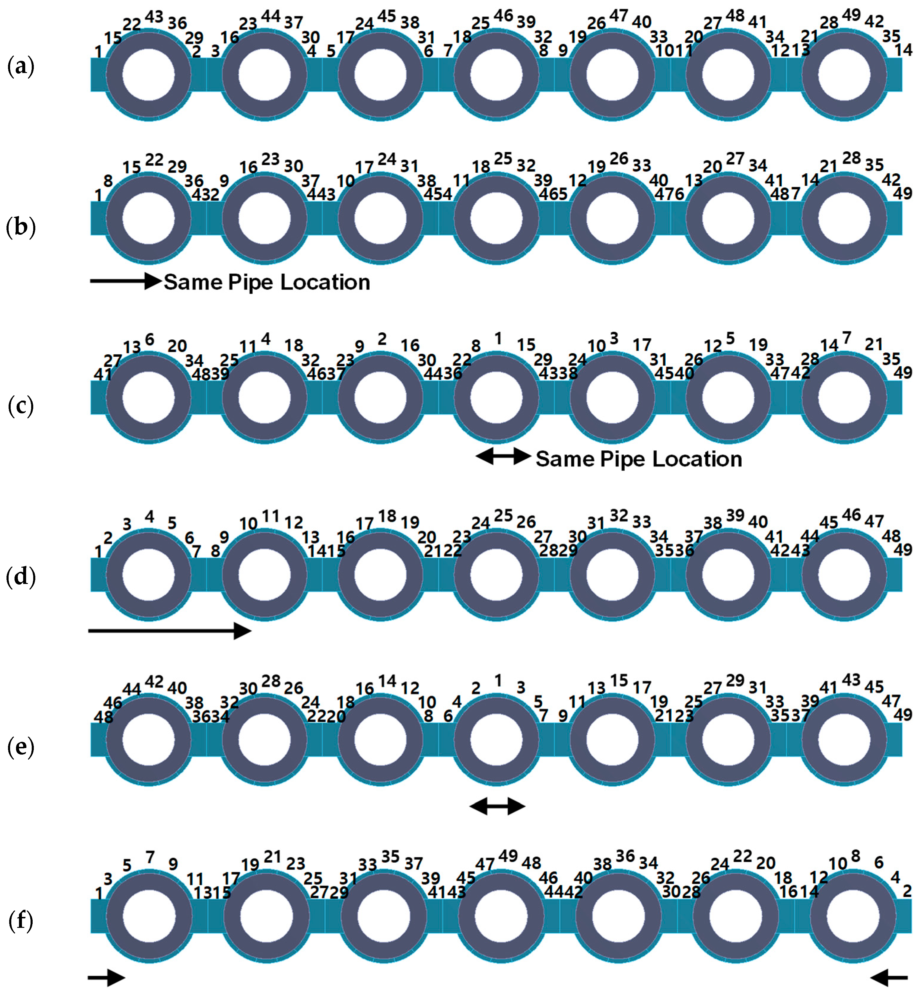
3.2. Overlay Welding Sequence

The welding sequence is analyzed in six cases, including the current overlay welding process (Reference case). The overlay welding is conducted under the conditions of a single welding carriage. A total of seven lines are utilized for the overlay welding process. One pipe is divided into five sections: the lower left, the upper left, the center, the upper right, and the lower right. Two membranes are positioned on both sides of the pipe, as illustrated in Figure 9.
The current welding sequence is designated as the Reference case. The Reference case is welded in the following order: The initial step is to weld all membranes in sequence, followed by the lower left corner of each pipe. Subsequently, the upper left corner of each pipe is welded. Subsequently, the sequence progresses to the lower right corner and then the upper right corner of each pipe. Finally, the center of each pipe is welded. Figure 3 shows the results of performing a weld following the methodology described in the Reference case.
In the analysis cases from CASE 1 to CASE 5, the sequence does not start with the membranes because the goal is to understand the welding deformation tendencies based on the welding sequence. The welding sequence for all analysis cases is shown in Figure 10. In CASE 1, the overlay welding process begins with the left membrane of each pipe, followed by the lower left, upper left, center, upper right, and lower right sections of each pipe. Finally, the right membrane of each pipe is welded. In CASE 2, the process starts from the middle pipe and alternates left and right. Overlay welding proceeds in the order of the center, upper left, upper right, lower left, lower right, left membrane, and right membrane. In CASE 3, the process starts from the left and proceeds to the right. In CASE 4, the welding starts from the center of the middle pipe and alternates left and right. In CASE 5, the welding alternates from the leftmost and rightmost ends towards the center.

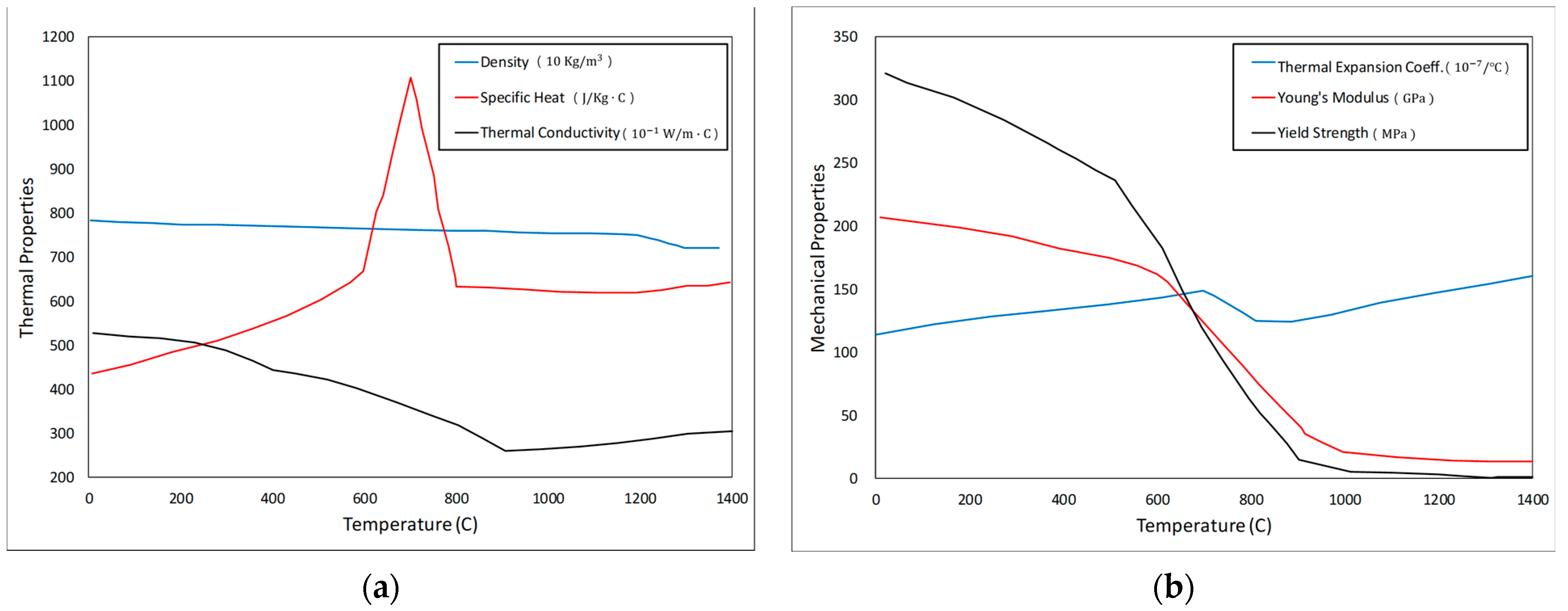
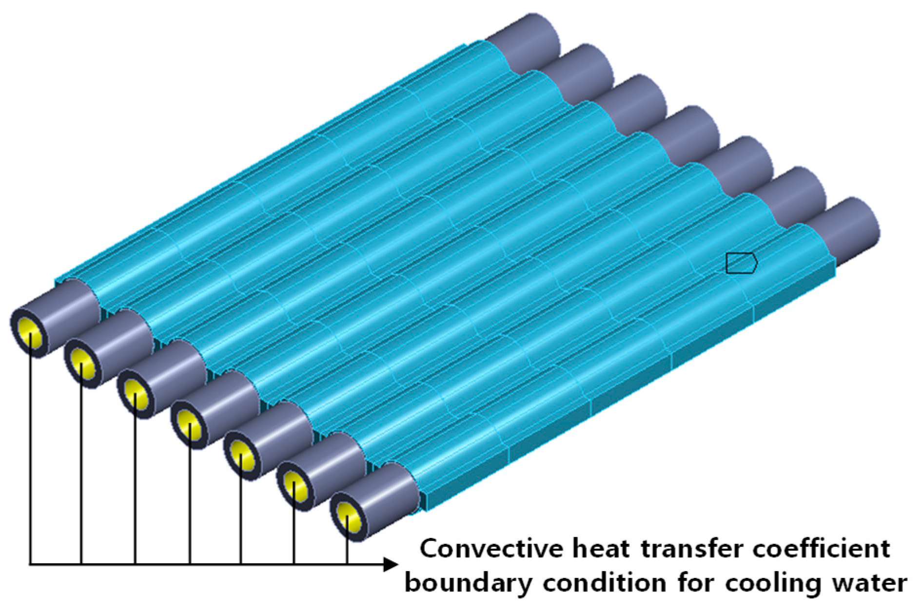
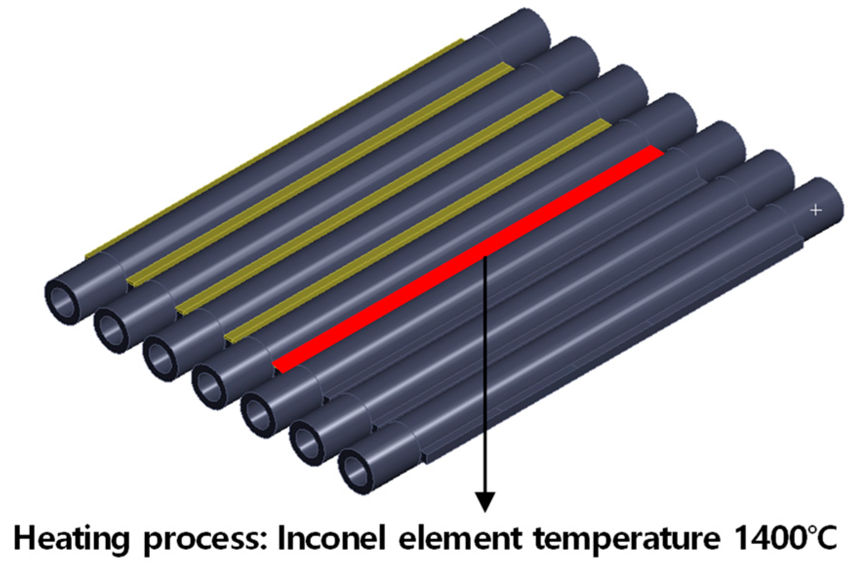
3.3. Boundary Condition for Thermal Elasto-Plastic Analysis

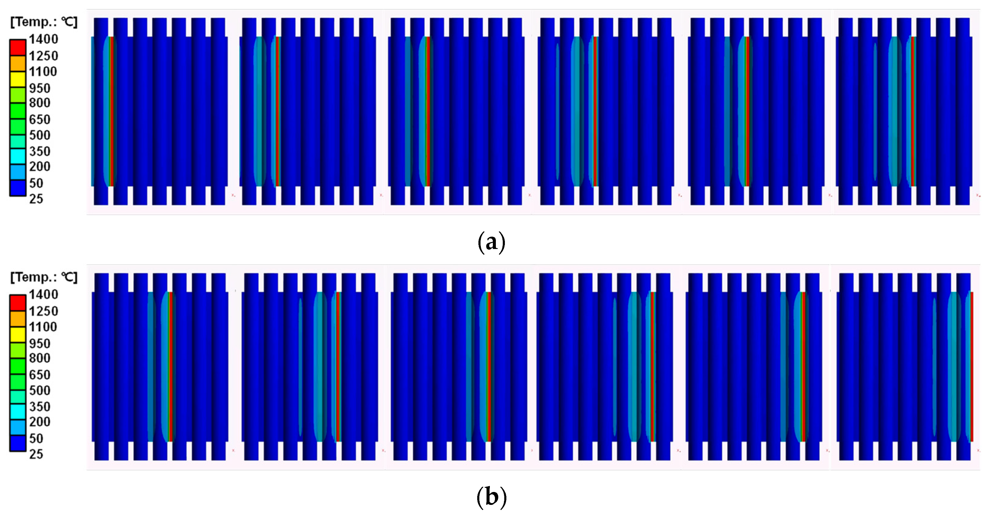
3.3.1. Heat Transfer Analysis

The first step for thermal elasto-plastic analysis is to perform heat transfer analysis. There are three boundary conditions for heat transfer analysis. First, since the structure is exposed to air during overlay welding, natural convection occurs. The air convection heat transfer coefficient for the natural convection condition is 20 W/m2·K, and the ambient air temperature is assumed to be 22 °C. These conditions are applied to the external area of the entire structure.
Additionally, during overlay welding, cooling water flows inside the pipe panel, which is considered convective heat transfer. The convective heat transfer coefficient, as illustrated in Figure 11, represents the heat transfer effect by cooling water. The convective heat transfer coefficient for the coolant flowing inside the pipe can be calculated using the internal forced convection equation in Equation (2). In Equation (2), K represents the thermal conductivity of water, while D denotes the internal diameter of the pipe. In the actual process, the thermal conductivity of water, K, is 0.629 W/m·K, given that the temperature of the internal cooling water is approximately 40 °C. As illustrated in Figure 4, the internal diameter of the pipe is 23.5 mm. Consequently, the value of the convective heat transfer coefficient by the coolant inside the pipe is calculated to be 116.7 W/m2·K.
h = 4.36 × K/D
During overlay welding, the temperature of the welding part rises to about 1400 °C, so the temperature of the welding part is assumed to be 1400 °C. During the heating step, one volume segment of the pipe is heated to 1400 °C along its entire length in the z-direction simultaneously for 10 s (Figure 12). The total heating time is 490 s (49 welding lines in total), and the cooling time at room temperature is 3600 s (1 h).
To simulate a realistic overlay welding process, ANSYS APDL commands were used to generate elements for the heating step. Figure 13 shows the heating step of overlay welding as a function of time for the Reference case.

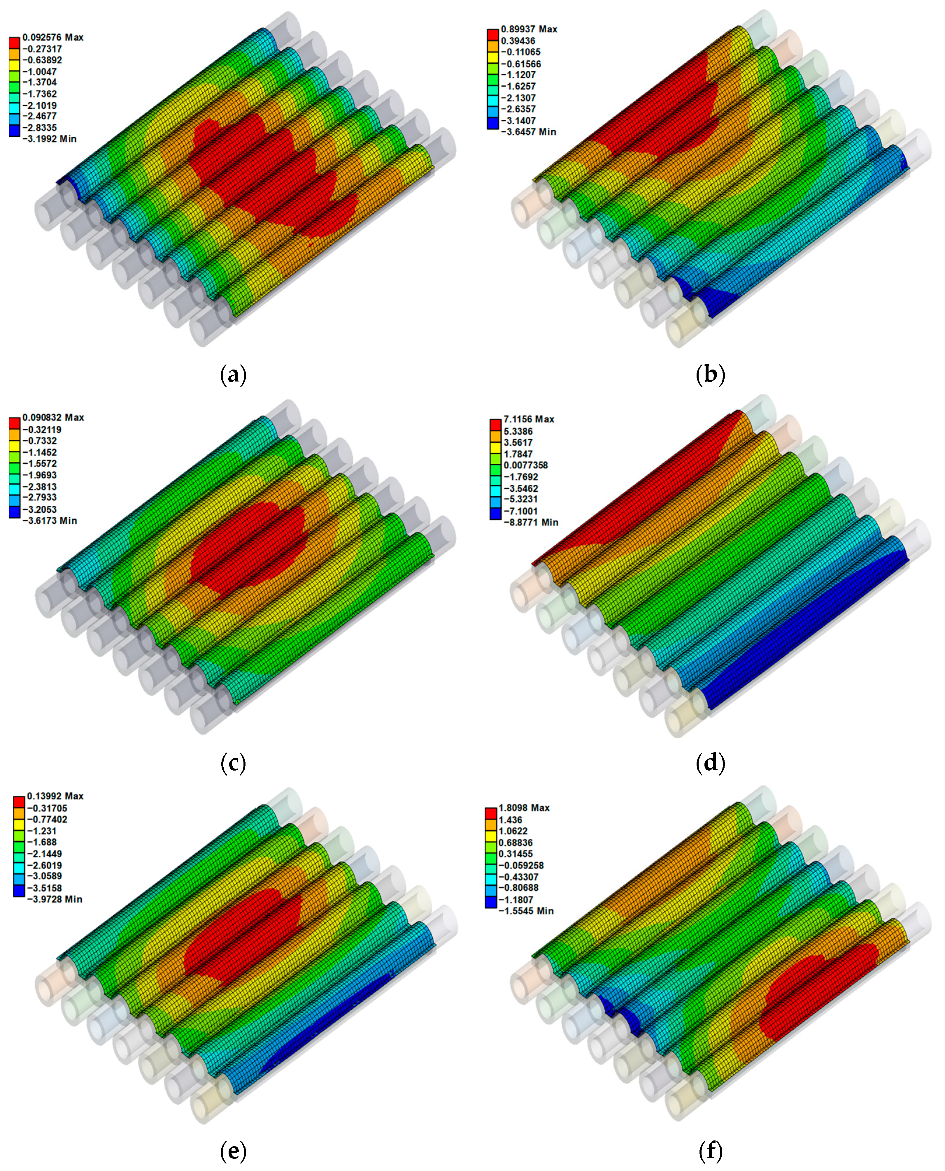
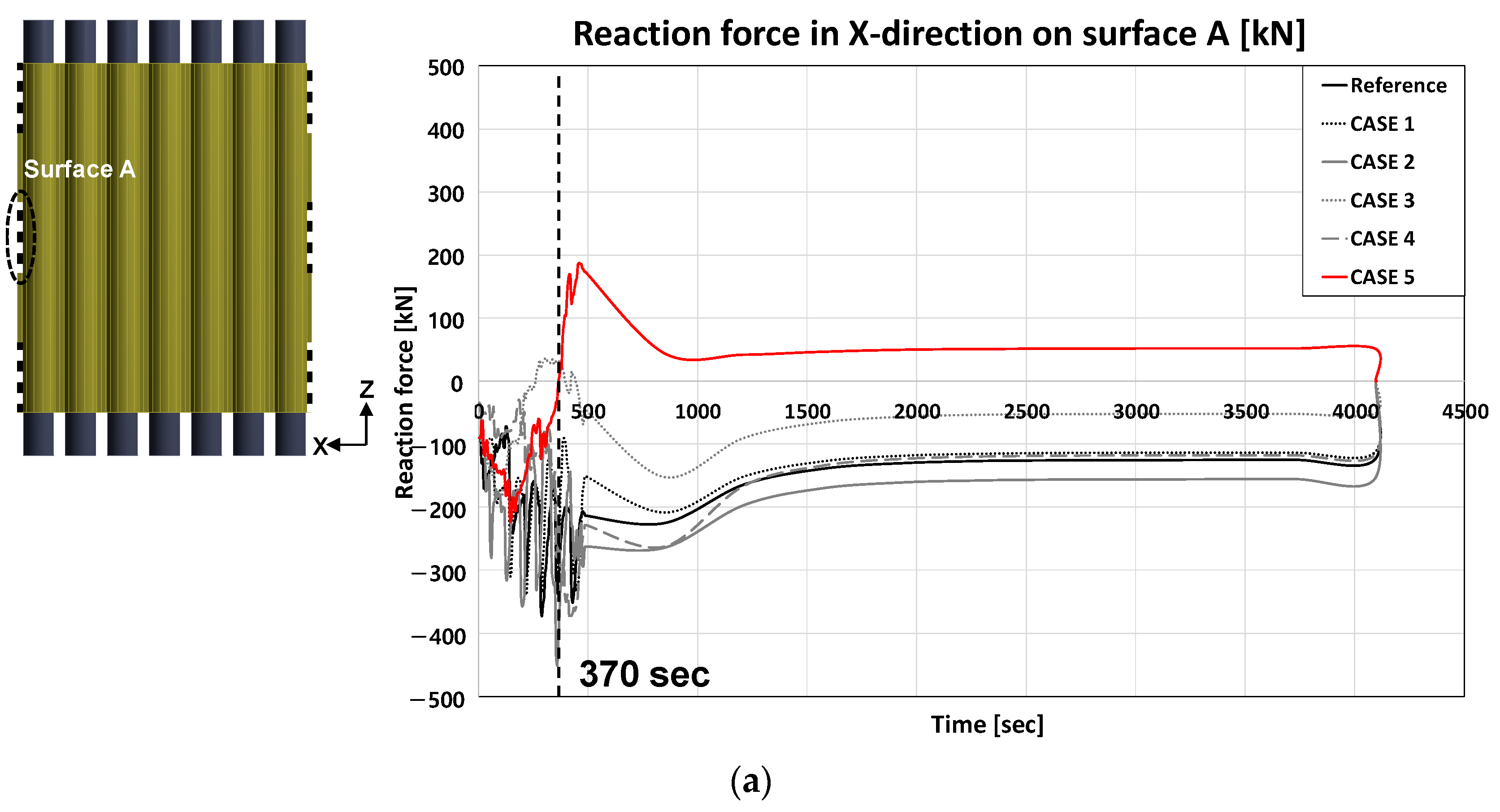
3.3.2. Structural Analysis

Figure 14 shows the geometric constraint of the structure used to perform the structural analysis after the heat transfer analysis. To implement the actual constraints, a portion of the leftmost and rightmost membranes are constrained.
After both the heating and cooling processes are completed, an additional static structural analysis is performed to remove the constraints. The final welding deformation is then calculated.

4. Overlay Welding Thermal Elasto-Plastic Analysis Results

Figure 15 shows the temperature distribution results for selected time steps from the heat transfer analysis described in the previous section. These results pertain to steps 3 through 14 of the Reference case in Figure 10a. The temperature distribution at each time increment is recorded and subsequently used in the structural analysis to calculate thermal deformation.
Figure 16 shows the y-direction (out-of-plane) deformation results of the thermal elasto-plastic analysis of the overlay welding on the water wall panel of the SRF boiler. To compare the welding deformation of the Reference case and the other cases proposed in this study, both the maximum y-direction deformation and the total y-direction deviation of all nodes on the overlay-welded surface were considered, as shown in the figures. The results show that the welding deformation is minimized in CASE 5. In CASE 5, the welding is performed alternately from the leftmost and rightmost parts of the structure toward the center pipe, as shown in Figure 10.
To quantify the weld deformation of the structure for each sequence, the sum of the deformation deviations in the y-direction at the nodes of the overlay-welded plane was calculated as shown in Figure 17. If these values are added as they are, the positive and negative values cancel each other out. So, the squared values are added, and the deviation is defined by Equation (3).
Total   of   deformation   deviation   =   i Number   of   total   node ( y i ) 2
The results of analyzing the overlay welding deformation using this method are shown in Figure 18. These results quantify the values in CASES 1–5 when the Reference is set to 100%.
To analyze the cause of the deformation difference due to the welding sequence, the reaction forces at the boundaries (surfaces A and B in the figures) during the welding process were calculated and compared between the Reference case and CASES 1–5. As shown in the graphs in Figure 19, the structure tends to expand during heating, causing compressive forces at the boundaries. However, after 370 s, unlike the other cases, tensile forces are acting on the structure in CASE 5. These tensile forces help minimize the deformation of the structure. In addition, the reason for the minimal welding deformation in CASE 5 is that as welding begins from the parts closest to the fixed ends of the structure, the constraints make deformation less likely. Furthermore, as welding progresses inward, the already-welded outer parts cool and help prevent deformation of the structure.

5. Comparison with Full-Size Analysis Model Results

The analysis was performed by modeling the actual size of the SRF boiler water wall panel, and comparative validation was conducted for the optimal welding sequence derived from the reduced model results. The actual water wall panel structure model used in the analysis is shown in Figure 20, with dimensions of 3350 mm in width and 783 mm in height. For efficiency, the model was created using shell elements. All material properties were applied identically to those in the reduced model analysis. The mesh is shown in Figure 21, with a total of 615,820 hexahedral elements and 639,549 nodes.
The boundary conditions were also set to reflect the actual constraints, with part of the left and right membranes constrained. These constraints were removed after the cooling phase.
The analysis was performed for the welding sequences of the Reference case and CASE 5. The resulting y-directional displacement field is shown in Figure 22. To compare the overall amount of welding deformation according to the welding sequence, the sum of the deformation deviations was also calculated using Equation (3), as shown in Figure 23. Similar to the results of the reduced model, it can be seen that the deformation deviation of CASE 5 is lower than that of the reference case. In particular, the results of CASE 5 are within 15% (85% welding deformation deviation reduction) of the reference case results, demonstrating the validity of the methodology for full-size overlay-welded structures.

6. Conclusions

In this study, thermo-elasto-plastic analysis was conducted to investigate the effects of changes in overlay welding sequences on welding deformation. For the six overlay welding sequences, the maximum deformation in the Y direction was compared with the total deformation deviation of the welded surface. It is confirmed that the welding deformation amount of CASE 5 is minimized considering the total deformation deviation. CASE 5 is a method of welding alternately from the left and right sides of the structure to the center pipe.
The reason why the welding deformation is minimized in CASE 5 is that deformation cannot easily occur due to the constraint condition when welding is performed from a portion near the fixed portion in a state where both ends of the structure are fixed. In addition, when the welding progresses inward, the outer part that has already been welded serves to prevent the deformation of the structure by cooling. In other words, the inside of the weld is contracted by a stronger load. This is because when the inner part is welded, the welded part tends to expand due to heating, but the outer part that has already been welded contracts to suppress the occurrence of deformation.
The derived optimal overlay welding sequence was validated through thermo-elasto-plastic analysis using a full-scale model. When the overlay welding was performed on the water wall panel of the SRF boiler using the CASE 5 welding sequence derived from this study, an 85% reduction in welding deformation deviation was observed.

Author Contributions

Conceptualization, H.-L.J. and S.K.; methodology, S.K.; software, H.-L.J.; validation, S.K., H.-L.J. and H.R.; formal analysis, H.R.; investigation, H.R.; resources, S.K.; data curation, S.K.; writing—original draft preparation, H.-L.J.; writing—review and editing, S.K.; visualization, S.K.; supervision, S.K.; project administration, S.K.; funding acquisition, H.-L.J. All authors have read and agreed to the published version of the manuscript.

Funding

This research was supported by a Korea Agency for Infrastructure Technology Advancement (KAIA) grant funded by the Ministry of Land, Infrastructure and Transport (Grant RS-2023-00238018).

Data Availability Statement

The original contributions presented in the study are included in the article, further inquiries can be directed to the corresponding author.

Conflicts of Interest

The authors declare no conflicts of interest.

References

  1. Rong, Y.; Xu, J.; Huang, Y.; Zhang, G. Review on Finite Element Analysis of Welding Deformation and Residual Stress. Sci. Technol. Weld. Join. 2017, 23, 198–208. [Google Scholar] [CrossRef]
  2. Narang, H.K.; Mahapatra, M.M.; Jha, P.K.; Sridhar, P.; Biswas, P. Experimental and Numerical Study on Effect of Weld Reinforcement on Angular Distortion of SAW Square Butt Welded Plates. J. Weld. Join. 2018, 36, 48–59. [Google Scholar] [CrossRef]
  3. Deng, D.; Liang, W.; Murakawa, H. Determination of Welding Deformation in Fillet-Welded Joint by Means of Numerical Simulation and Comparison with Experimental Results. J. Mater. Process. Technol. 2007, 183, 219–225. [Google Scholar] [CrossRef]
  4. Obeid, O.; Alfano, G.; Bahai, H. Thermo-Mechanical Analysis of a Single-Pass Weld Overlay and Girth Welding in Lined Pipe. J. Mater. Eng. Perform. 2017, 26, 3861–3876. [Google Scholar] [CrossRef]
  5. Rong, Y.; Zhang, G.; Huang, Y. Study on Deformation and Residual Stress of Laser Welding 316L T-Joint Using 3D/Shell Finite Element Analysis and Experiment Verification. Int. J. Adv. Manuf. Technol. 2017, 89, 2077–2085. [Google Scholar] [CrossRef]
  6. Rong, Y.; Zhang, G.; Huang, Y. Study of Welding Distortion and Residual Stress Considering Nonlinear Yield Stress Curves and Multi-Constraint Equations. J. Mater. Eng. Perform. 2016, 25, 4484–4494. [Google Scholar] [CrossRef]
  7. Kim, J.W.; Jang, B.S.; Kang, S.W. A Study on an Efficient Prediction of Welding Deformation for T-Joint Laser Welding of Sandwich Panel Part II: Proposal of a Method to Use Shell Element Model. Int. J. Nav. Archit. Ocean Eng. 2014, 6, 245–256. [Google Scholar] [CrossRef]
  8. Murakawa, H.; Oda, I.; Itoh, S.; Serizawa, H.; Shibahara, M.; Nishikawa, H. Iterative Substructure Method for Fast FEM Analysis of Mechanical Problems in Welding. Prepr. Natl. Meet. JWS 2004, 75, 274–275. [Google Scholar]
  9. Huang, H.; Ma, N.; Hashimoto, T. Welding Deformation and Residual Stresses in Arc Welded Lap Joints by Modified Iterative Analysis. Sci. Technol. Weld. Join. 2015, 20, 571–577. [Google Scholar] [CrossRef]
  10. Murakawa, H.; Ma, N.; Huang, H. Iterative Substructure Method Employing Concept of Inherent Strain for Large-Scale Welding Problems. Weld. World 2015, 59, 53–63. [Google Scholar] [CrossRef]
  11. Ikushima, K.; Shibahara, M. Prediction of Residual Stresses in Multi-Pass Welded Joint Using Idealized Explicit FEM Accelerated by a GPU. Comput. Mater. Sci. 2014, 93, 62–67. [Google Scholar] [CrossRef]
  12. Ikushima, K.; Itoh, S.; Shibahara, M. Development of Idealized Explicit FEM Using GPU Parallelization and Its Application to Large-Scale Analysis of Residual Stress of Multi-Pass Welded Pipe Joint. Weld. World 2015, 59, 589–595. [Google Scholar] [CrossRef]
  13. Ma, N. An Accelerated Explicit Method with GPU Parallel Computing for Thermal Stress and Welding Deformation of Large Structure Models. Int. J. Adv. Manuf. Technol. 2016, 87, 2195–2211. [Google Scholar] [CrossRef]
  14. Ma, N. An Accelerated Explicit Method and GPU Parallel Computing for Thermal Stress and Welding Deformation of Automotive Parts. Int. J. Appl. Mech. 2016, 8, 1650023. [Google Scholar] [CrossRef]
  15. Ueda, Y.; Fukuda, K.; Tanigawa, M. New Measuring Method of Three Dimensional Residual Stresses Based on Theory of Inherent Strain. Trans. Jpn. Weld. Res. Inst. 1979, 8, 249–256. [Google Scholar]
  16. Nomoto, T.; Takechi, S.; Aoyama, K. Basic Studies on Accuracy Management System Based on Estimation of Weld Deformations. J. Soc. Nav. Archit. Jpn. 1997, 181, 249–260. [Google Scholar] [CrossRef]
  17. Lee, J.S.; Kim, S.I.; Cho, Y.G.; Lee, H.W. Prediction of Welding Deformation of Panel Block Using Simplified Analysis Method. In Proceedings of the Annual Spring Meeting, The Society of Naval Architects of Korea, Geoje, Republic of Korea, 18 April 1996; pp. 271–276. [Google Scholar]
  18. Kim, S.I.; Lee, J.S. Development of Simple Prediction Method for Welding Distortion in Fillet Joints. In Proceedings of the Annual Spring Meeting, The Society of Naval Architects of Korea, Geoje, Republic of Korea, 18 April 1996; pp. 265–270. [Google Scholar]
  19. Jang, C.D.; Seo, S.I.; Ko, D.E. A Study on the Simulation of Line Heating Process Using a Simplified Thermal Elasto-Plastic Analysis Method. Proc. Pract. Des. Ships Mob. Unit 1995, 2, 1421–1432. [Google Scholar]
  20. Kang, S.; Kim, J.; Jang, Y.; Lee, G. Welding Deformation Analysis Using an Inherent Strain Method for Friction Stir Welded Electric Vehicle Aluminum Battery Housing, Considering Productivity. Appl. Sci. 2019, 9, 3848. [Google Scholar] [CrossRef]
  21. Kim, Y.; Kim, J.; Kang, S. A Study on Welding Deformation Prediction for Ship Blocks Using the Equivalent Strain Method Based on Inherent Strain. Appl. Sci. 2019, 9, 4906. [Google Scholar] [CrossRef]
  22. Kim, T.J.; Jang, B.S.; Kang, S.W. Welding Deformation Analysis Based on Improved Equivalent Strain Method Considering the Effect of Temperature Gradients. Int. J. Nav. Archit. Ocean Eng. 2014, 7, 157–173. [Google Scholar] [CrossRef]
  23. Kim, T.J.; Jang, B.S.; Kang, S.W. Welding Deformation Analysis Based on Improved Equivalent Strain Method to Cover External Constraint During Cooling Stage. Int. J. Nav. Archit. Ocean Eng. 2015, 7, 805–816. [Google Scholar] [CrossRef]
  24. Lee, J.M.; Seo, H.D.; Chung, H. Efficient Welding Distortion Analysis Method for Large Welded Structures. J. Mater. Process. Technol. 2018, 256, 36–50. [Google Scholar] [CrossRef]
  25. Rong, Y.; Wang, L.; Wu, R.; Xu, J. Visualization and Simulation of 1700MS Sheet Laser Welding Based on Three-Dimensional Geometries of Weld Pool and Keyhole. Int. J. Therm. Sci. 2022, 171, 107257. [Google Scholar] [CrossRef]
  26. Gannon, L.; Liu, Y.; Pegg, N.; Smith, M. Effect of Welding Sequence on Residual Stress and Distortion in Flat-Bar Stiffened Plates. Mar. Struct. 2010, 23, 385–404. [Google Scholar] [CrossRef]
  27. Kang, M.; Seo, J.; Chung, H. Ship Block Assembly Sequence Planning Considering Productivity and Welding Deformation. Int. J. Nav. Archit. Ocean Eng. 2018, 10, 450–457. [Google Scholar] [CrossRef]
  28. Romanin, L.; Ferro, P.; Berto, F. A Simplified Non-Linear Numerical Method for the Assessment of Welding Induced Deformations. Mar. Struct. 2021, 78, 102982. [Google Scholar] [CrossRef]
  29. Tabar, R.S.; Wärmefjord, K.; Söderberg, R.; Lindkvist, L. A Novel Rule-Based Method for Individualized Spot Welding Sequence Optimization with Respect to Geometrical Quality. J. Manuf. Sci. Eng. 2019, 141, 111013. [Google Scholar] [CrossRef]
  30. Huang, M.W.; Hsieh, C.C.; Jasbir, S.A. A Genetic Algorithm for Sequencing Type Problems in Engineering Design. Int. J. Numer. Methods Eng. 1997, 40, 3105–3115. [Google Scholar] [CrossRef]
  31. Kadivar, M.H.; Jafarpur, K.; Baradaran, G.H. Optimizing Welding Sequence with Genetic Algorithm. Comput. Mech. 2000, 26, 514–519. [Google Scholar] [CrossRef]
  32. Romero-Hdz, J.; Saha, B.N.; Tstutsumi, S.; Fincato, R. Incorporating Domain Knowledge into Reinforcement Learning to Expedite Welding Sequence Optimization. Eng. Appl. Artif. Intell. 2020, 91, 103612. [Google Scholar] [CrossRef]
  33. Ha, Y. Analytical Methodology Obtaining an Optimal Welding Sequence for Least Distortion of Welded Structure. J. Weld. Join. 2013, 31, 54–59. [Google Scholar]
  34. Kang, S.; Yun, W.; Kim, H.; Kim, J.; Ji, C.; Lee, K.; Chun, K. A Study on Minimizing Welding Deformation of Joints for the Sealing of Emission After-Treatment Structure. Materials 2021, 14, 6982. [Google Scholar] [CrossRef] [PubMed]
  35. Li, Z.; Feng, G.; Deng, D.; Luo, Y. Investigating welding distortion of thin-plate stiffened panel steel structures by means of thermal elastic plastic finite element method. J. Mater. Eng. Perform. 2021, 30, 3677–3690. [Google Scholar] [CrossRef]
  36. Hammad, A.; Churiaque, C.; Sánchez-Amaya, J.M.; Abdel-Nasser, Y. Experimental and numerical investigation of hybrid laser arc welding process and the influence of welding sequence on the manufacture of stiffened flat panels. J. Manuf. Process. 2021, 61, 527–538. [Google Scholar] [CrossRef]
  37. Yuan, M.; Liu, S.; Sun, H.; Gao, Y.; Dai, X.; Chen, W. FEM research on welding thermal deformation of copper alloy sheet and optimization of welding sequence. Coatings 2021, 11, 1287. [Google Scholar] [CrossRef]
  38. Choi, M.; Wu, C.; Kim, J.W. Numerical optimization of the welding sequence for mitigating welding deformation in aluminum pipe structures by using a genetic algorithm. Int. J. Precis. Eng. Manuf. 2020, 21, 2323–2333. [Google Scholar] [CrossRef]
  39. Wu, C.; Wang, C.; Kim, J.W. Welding sequence optimization to reduce welding distortion based on coupled artificial neural network and swarm intelligence algorithm. Eng. Appl. Artif. Intell. 2022, 114, 105142. [Google Scholar] [CrossRef]
  40. Rajkumar, V.; Arjunan, T.V.; Kannan, A.R. Metallurgical and mechanical investigations of Inconel 625 overlay welds produced by GMAW-hardfacing process on AISI 347 pipes. Mater. Res. Express 2019, 6, 076534. [Google Scholar] [CrossRef]
  41. Varghese, P.; Vetrivendan, E.; Dash, M.K.; Ningshen, S.; Kamaraj, M.; Mudali, U.K. Weld overlay coating of Inconel 617 M on type 316 L stainless steel by cold metal transfer process. Surf. Coat. Technol. 2019, 357, 1004–1013. [Google Scholar] [CrossRef]
  42. Rajesh, S.R.; Yoo, J.; Park, J.; Choi, D. Thermal Deformation Analysis Methodology Development for Inconel Overlaying. J. Weld. Join. 2022, 40, 107–117. [Google Scholar] [CrossRef]
  43. Lee, D.W. Thermo-Elasto-Plastic Modeling of GMAW Using the Finite Element Method. Ph.D. Thesis, Seoul National University, Seoul, Republic of Korea, 1995. [Google Scholar]
  44. Mirkoohi, E.; Liang, S.Y.; Tran, H.C.; Lo, Y.L.; Chang, Y.C.; Lin, H.Y. Mechanics Modeling of Residual Stress Considering Effect of Preheating in Laser Powder Bed Fusion. J. Manuf. Mater. Process. 2021, 5, 46. [Google Scholar] [CrossRef]
  45. Logan, D.L. A First Course in the Finite Element Method, 6th ed.; Cengage Learning: Boston, MA, USA, 2016; pp. 727–730. [Google Scholar]
Figure 1. Water wall panel in SRF (solid refuse fuel) boiler.
Metals 14 00684 g001
Figure 2. Overlay welding process with welding automation device.
Metals 14 00684 g002
Figure 3. Welding deformation of overlay-welded pipe panel.
Metals 14 00684 g003
Figure 4. Configuration, materials, and dimensions of overlay-welded pipe panel (units: mm).
Metals 14 00684 g004
Figure 5. Temperature-dependent material properties of SS400: (a) thermal properties; (b) mechanical properties (Adapted from Ref. [43]).
Metals 14 00684 g005
Figure 6. Temperature-dependent material properties of Inconel 718: (a) thermal properties; (b) mechanical properties (Adapted from Ref. [44]).
Metals 14 00684 g006
Figure 7. Thermal elasto-plastic analysis for overlay welding.
Metals 14 00684 g007
Figure 8. Mesh of overlay-welded pipe panel.
Metals 14 00684 g008
Figure 9. Pipe panel overlay welding parts (total of 6 parts in a pipe including membrane).
Metals 14 00684 g009
Figure 10. Overlay welding sequence for thermal elasto-plastic analysis; (a) Reference, (b) CASE 1, (c) CASE 2, (d) CASE 3, (e) CASE 4, (f) CASE 5. (The arrows indicate the welding direction up to the first two pipes.)
Metals 14 00684 g010
Figure 11. Cooling water convection’s effect on inner pipe surface.
Metals 14 00684 g011
Figure 12. Heat source input conditions for overlay welding.
Metals 14 00684 g012
Figure 13. Step-by-step Inconel element generation at weld for simulating overlay welding processes.
Metals 14 00684 g013
Figure 14. Geometric constraint boundary condition during overlay welding.
Metals 14 00684 g014
Figure 15. Temperature distribution of the pipes according to the reference welding sequence shown in Figure 10a: (a) from step 3 to step 8, (b) from step 9 to step 14.
Metals 14 00684 g015
Figure 16. Overlay welding thermal elasto-plastic analysis results in Y-deformation (unit: mm); (a) Reference, (b) CASE 1, (c) CASE 2, (d) CASE 3, (e) CASE 4, (f) CASE 5.
Metals 14 00684 g016
Figure 17. Y-direction deviation of the overlay-welded structure (conceptual diagrams). The blue and red arrows denote the (+) and (−) signs of out-of-plane displacement, respectively.
Metals 14 00684 g017
Figure 18. Total overlay welding deformation deviation results.
Metals 14 00684 g018
Figure 19. Reaction force results: (a) Surface A and (b) Surface B.
Metals 14 00684 g019aMetals 14 00684 g019b
Figure 20. Water wall panel structure specifications of a real SRF boiler.
Metals 14 00684 g020
Figure 21. Mesh for full-size model overlay welding thermal elasto-plastic analysis.
Metals 14 00684 g021
Figure 22. Overlay welding thermal elasto-plastic analysis results in Y-deformation: (a) Reference, (b) CASE 5.
Metals 14 00684 g022
Figure 23. Total overlay welding deformation deviation results of full-size overlay-welded structures.
Metals 14 00684 g023
Disclaimer/Publisher’s Note: The statements, opinions and data contained in all publications are solely those of the individual author(s) and contributor(s) and not of MDPI and/or the editor(s). MDPI and/or the editor(s) disclaim responsibility for any injury to people or property resulting from any ideas, methods, instructions or products referred to in the content.

