Article

Inconel 740H Prepared by Additive Manufacturing: Microstructure and Mechanical Properties

College of Chemistry and Materials Engineering, Anhui Science and Technology University, Bengbu 233000, China
*
Author to whom correspondence should be addressed.
Metals 2024, 14(7), 809; https://doi.org/10.3390/met14070809
Submission received: 5 June 2024 / Revised: 4 July 2024 / Accepted: 5 July 2024 / Published: 11 July 2024
(This article belongs to the Section Additive Manufacturing)

Abstract

:
An Inconel 740H nickel-based alloy was fabricated via wire arc additive manufacturing. The as-welded and heat-treated samples were analyzed to investigate their phase composition, microstructure, crystal structure, and mechanical properties. After heat treatment, the sample exhibited a columnar crystal zone microstructure consisting of a γ matrix + precipitated phase, the remelting zone metallographic structure was a γ matrix + precipitated phase, and the HAZ metallographic structure was a γ matrix + precipitated phase. Transmission electron microscopy (TEM) and electron backscatter diffraction (EBSD) were used to show that the welded sample exhibited many dislocations, a few inclusions, and carbides, nitrides, and γ’ precipitates in its crystal structure. In contrast, the crystal structure of the heat-treated sample exhibited a lower number of dislocations and significantly higher carbide and γ’ precipitate content. Moreover, the mechanical performance of these samples was excellent. This heat-treatment process improved the sample strength by about 200 MPa, leading to better high-temperature mechanical properties. This work is anticipated to offer theoretical and experimental support for using additive manufacturing methods in the manufacturing of nickel-based superalloy components.

1. Introduction

This Inconel 740H alloy is an age-hardened nickel-based superalloy that uses a γ’-Ni3 (Al, Ti, Nb) phase as the main strengthening phase as well as Mo and other elements as solid solution strengthening components. Increasing the Al content and reducing the Ti, Nb, and Si content in this alloy enhances the stability of its γ’ phase, inhibits precipitation of the needle η phase, and improves its high-temperature rupture, creep strength, oxidation resistance, and high-temperature steam corrosion properties compared with the original alloy [1,2,3,4,5].
It has been reported that heat treatment affects the microstructure and high-temperature performance of the Inconel 740H superalloy. The stability of the heat-treated microstructure and mechanical properties under long-term thermal conditions of 750 °C up to 5000 h were studied. The optimal heat-treatment conditions for maximizing creep performance were determined through creep tests (750 °C/270 MPa). The results showed that under the creep condition of 750 °C/270 MPa, Cr was concentrated at the grain boundaries of MC carbides with no specific orientation relationship. This is the result of the phase transformation MC + γ M23C6 + γ′ [6]. It has been reported that grain size and sheet thickness affect the creep rupture behavior of the Inconel 740H superalloy. The results show that creep strength and ductility are important factors influencing the overall creep performance of thin sheets. When the grain size is fine, performance degradation can be observed due to accelerated creep, or when the grain size is close to the sheet thickness, due to the loss of fracture ductility. Certain combinations of heat treatment and thickness can produce the typical, expected deformation creep performance. Historically, the “rule of thumb” for creep testing requires a minimum sample size of 3–5 grains to ensure uniform behavior [7]. It has been observed that Inconel 740H performs well against corrosion in supercritical carbon dioxide (S-CO2) at temperatures between 650 and 700 °C and a pressure of 25 MPa. The findings show that the Inconel 740H alloy experiences general oxidation, localized spallation, and internal oxidation. A dense Cr2O3 oxide layer forms quickly on the surface at these temperatures, offering significant corrosion resistance. Titanium-rich and niobium-rich oxides lead to nodular oxidation, while internal oxidation selectively targets aluminum. The causes of oxidation-induced spallation are also examined [8]. In simulated corrosive environments, such as 750 °C flue gas/coal ash resulting from the combustion of domestic high sulfur coal, Inconel 740H demonstrates superior corrosion resistance compared to alternative materials like Nimonic 263, Alloy 617B, and Haynes 282 [9]. Consequently, the Inconel 740H alloy is currently deemed the prime candidate for superheater or reheater tube applications within the temperature range of 700–760 °C for ultra-supercritical units [10]. This preference is attributed to its outstanding high-temperature stress rupture strength and commendable performance, enabling it to withstand corrosion in the high-temperature and high-pressure settings prevalent in intricate operational environments [11].
Additive manufacturing methods are a new category of material-forming technologies that have exhibited outstanding advantages such as rapid manufacturing cycles, low production costs, high utilization rates of materials, and good integration between the design and manufacturing processes [12]. These methods have highly promising application prospects in areas such as the aerospace, automotive, education, biomedical, and injection molding fields [13,14,15,16,17,18].
However, despite the existing literature, there remains a gap in the comprehensive understanding of the microstructural and material properties of Inconel 740H [19]. Therefore, this study endeavors to address this gap by examining the Inconel 740H alloy through the fabrication of samples using wire arc additive manufacturing. Through both theoretical analysis and experimental investigation, this research aims to contribute to the advancement and practical implementation of additive manufacturing techniques specifically tailored to the unique properties of the Inconel 740H alloy.

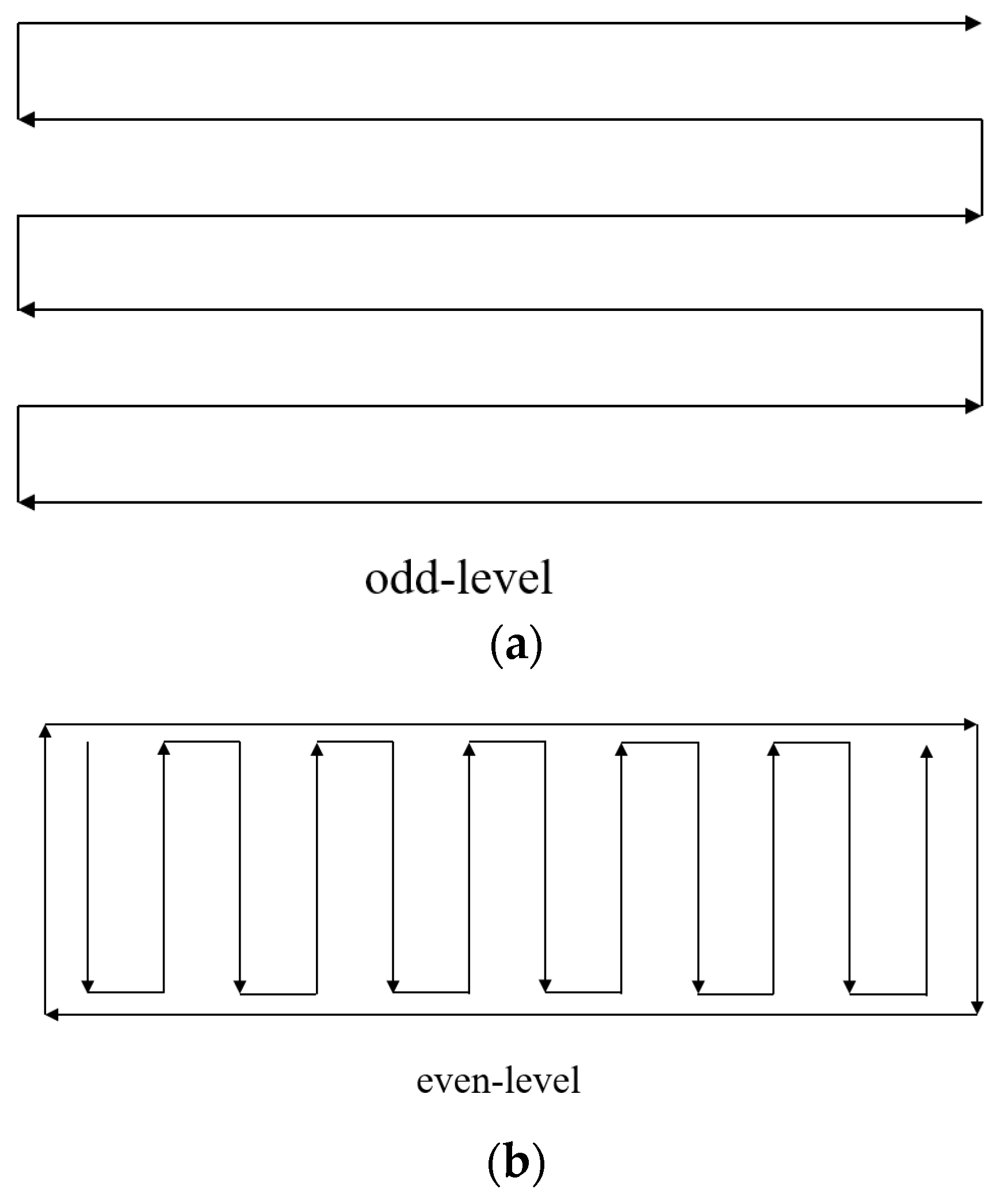
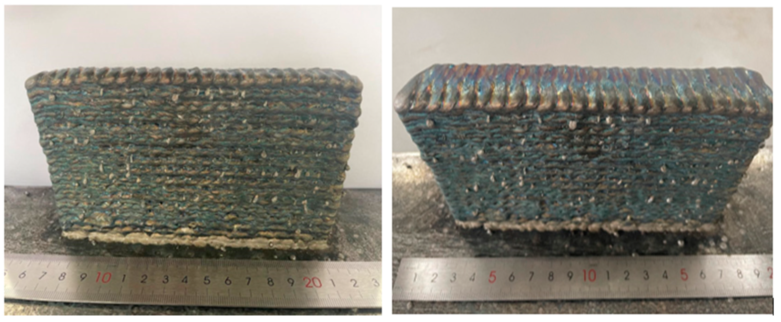
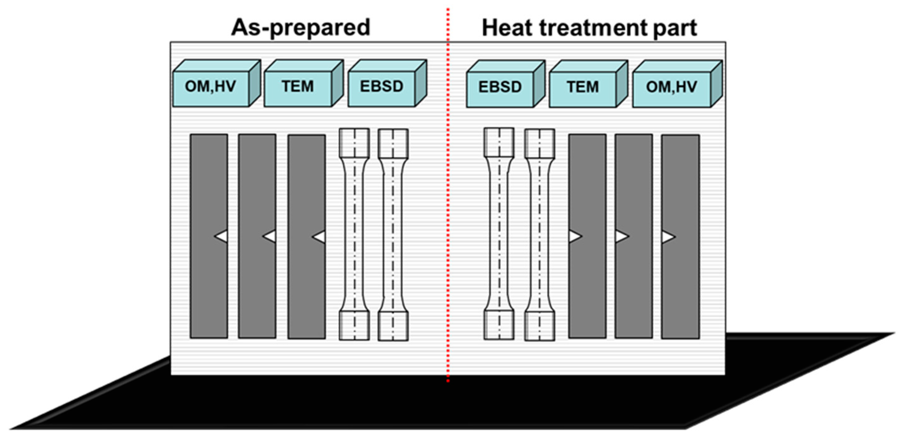
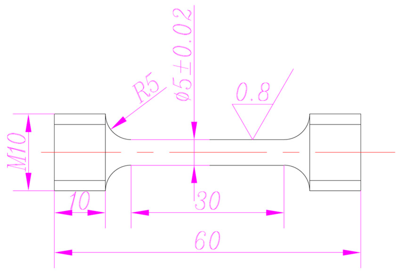
2. Materials and Methods

The Inconel filler metal 740H welding wire (UNS#: N07740, classification: AWS A5.14 ERNiCrCo-1, diameter: 1.2 mm) was produced by Special Metals. The composition of this wire is reported in Table 1. Arc additive manufacturing was performed using a MIG-350RP power supply and a six-axis AIR10-A industrial robot. The experimental base material was Q235 steel. Initially, single-layer single-channel, single-layer multi-channel, and multi-layer multi-channel tests were performed. Next, the best processing parameters were chosen based on the weld bead morphologies formed during the initial tests. These process parameters are reported in Table 2. The printing path is shown in Figure 1.
In this study, the printed thin-walled sample had dimensions of about 150 mm × 20 mm × 80 mm. After printing, the base plate was removed with a sawing machine. Next, this printed sample was cut into two and a half sections. One and a half sections were used to prepare heat-treated samples. These heat-treated specimens were solution-annealed at 1100 °C for 0.5 h, which was followed by water quenching. They were then aged for 16 h at 800 °C and air-cooled to obtain the final heat-treated samples.
A printed Inconel 740H nickel-based alloy sample obtained using arc additive manufacturing is displayed in Figure 2. This thin-wall sample exhibited a good shape and did not collapse. However, visible solid metal particles were caused by welding wire spatter in the sample-forming process.
The tensile properties of the as-welded and heat-treated samples were investigated at room temperature and 600 °C using a 300 kN material testing machine (INSTRON5587, Norwood, MA, USA), Each group consisted of two samples, with each pair of specimens designated for high-temperature and room-temperature tensile testing. Impact tests were performed with a pendulum impact machine (ZBC2602-B, Jinan, China) at room temperature with 3 samples in each group. These metallographic samples were etched with aqua regia solution. The microstructures of these etched samples were investigated using a ZEISS (Oberkochen, Germany) Observer.Z1m metallographic microscope. Transmission electron microscopy (JEM-2100, Tokyo, Japan) was used to investigate the sample crystal structures at a 200 kV accelerating voltage. The phase composition of the sample was analyzed by XRD experiment with XD-3X X-ray diffractometer. X-ray tube was Cu rake, working high voltage was 36 KV, working current of 24 mA, scanning speed was 2°/min, sampling step width was 0.02°, and the scanning range was between 10° and 90°. Vickers microhardness values were measured with a force of 200 gf and a 15 s holding time. The hardness testing points were positioned 2 mm from the top and left edges of the sample, with ten points in total spaced 1 mm apart. The arrangement of the hardness points formed a cross pattern. A Wilson (Chicago, IL, USA) VH3300 microhardness tester was used. The sampling position of these samples is displayed in Figure 3. The tensile specimen dimensions diagram is shown in Figure 4.

3. Results

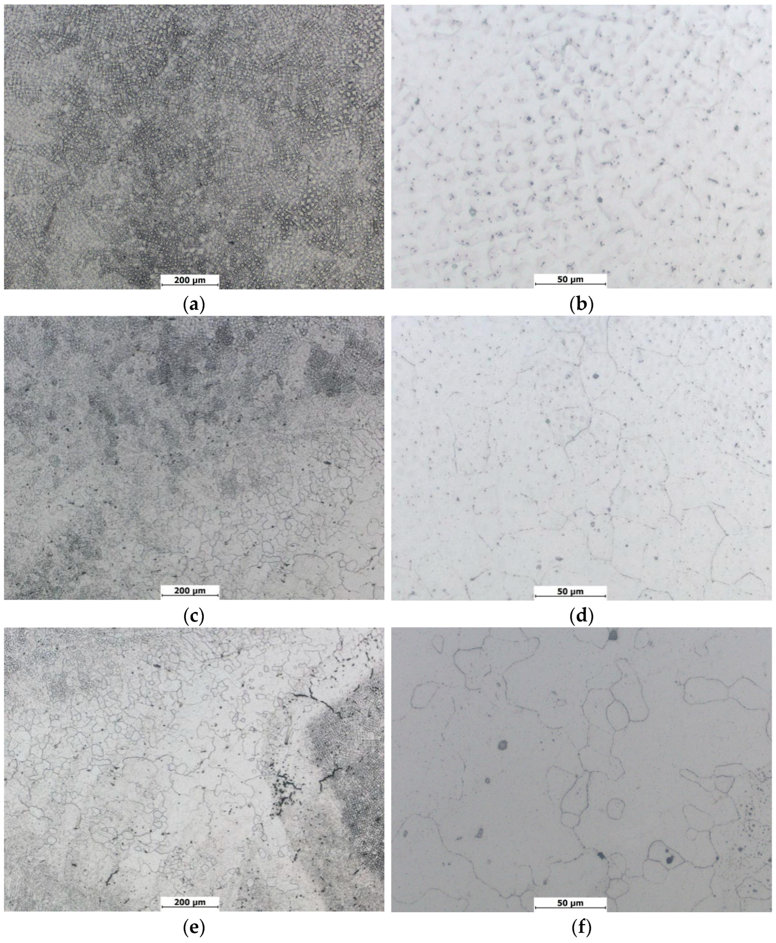
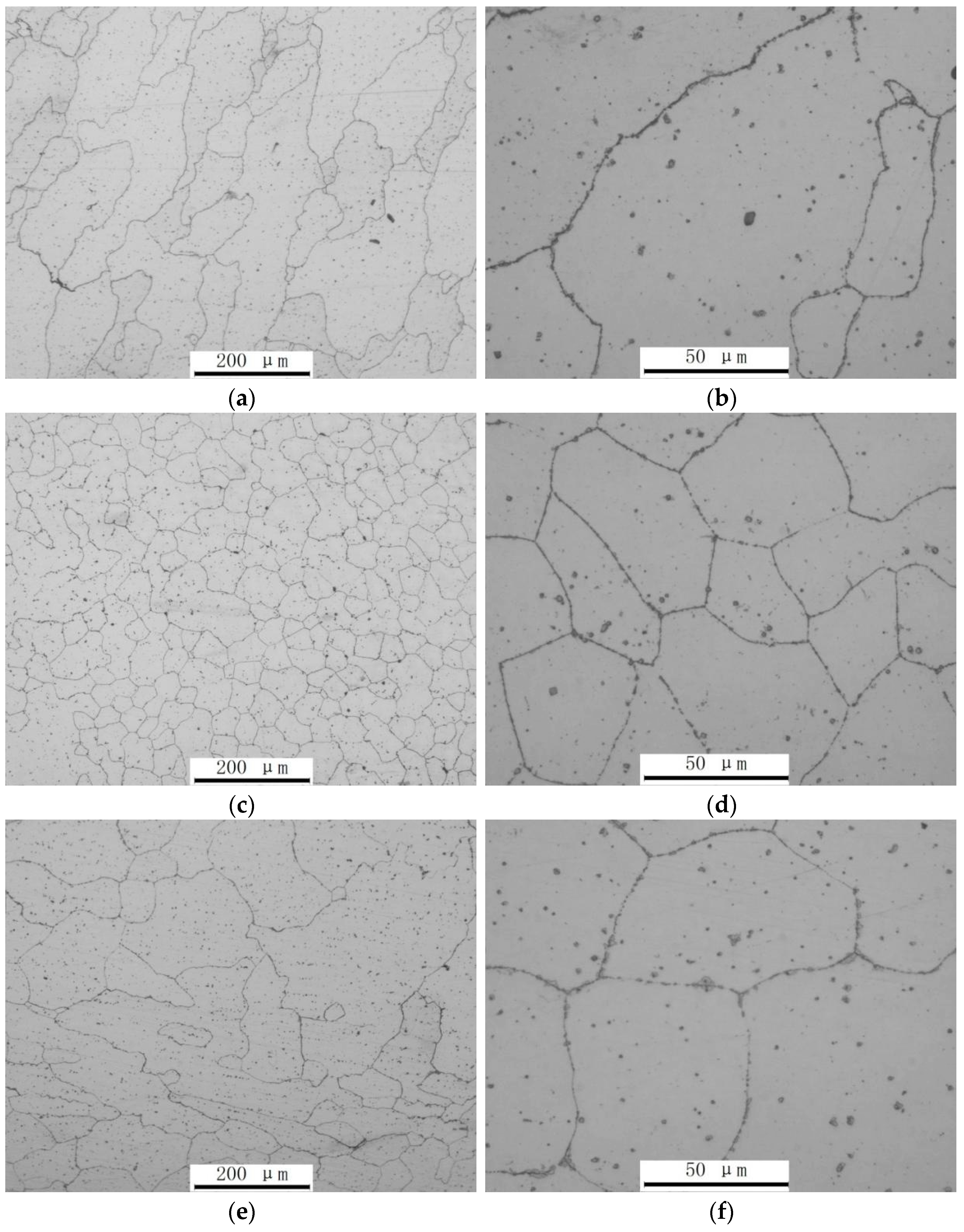
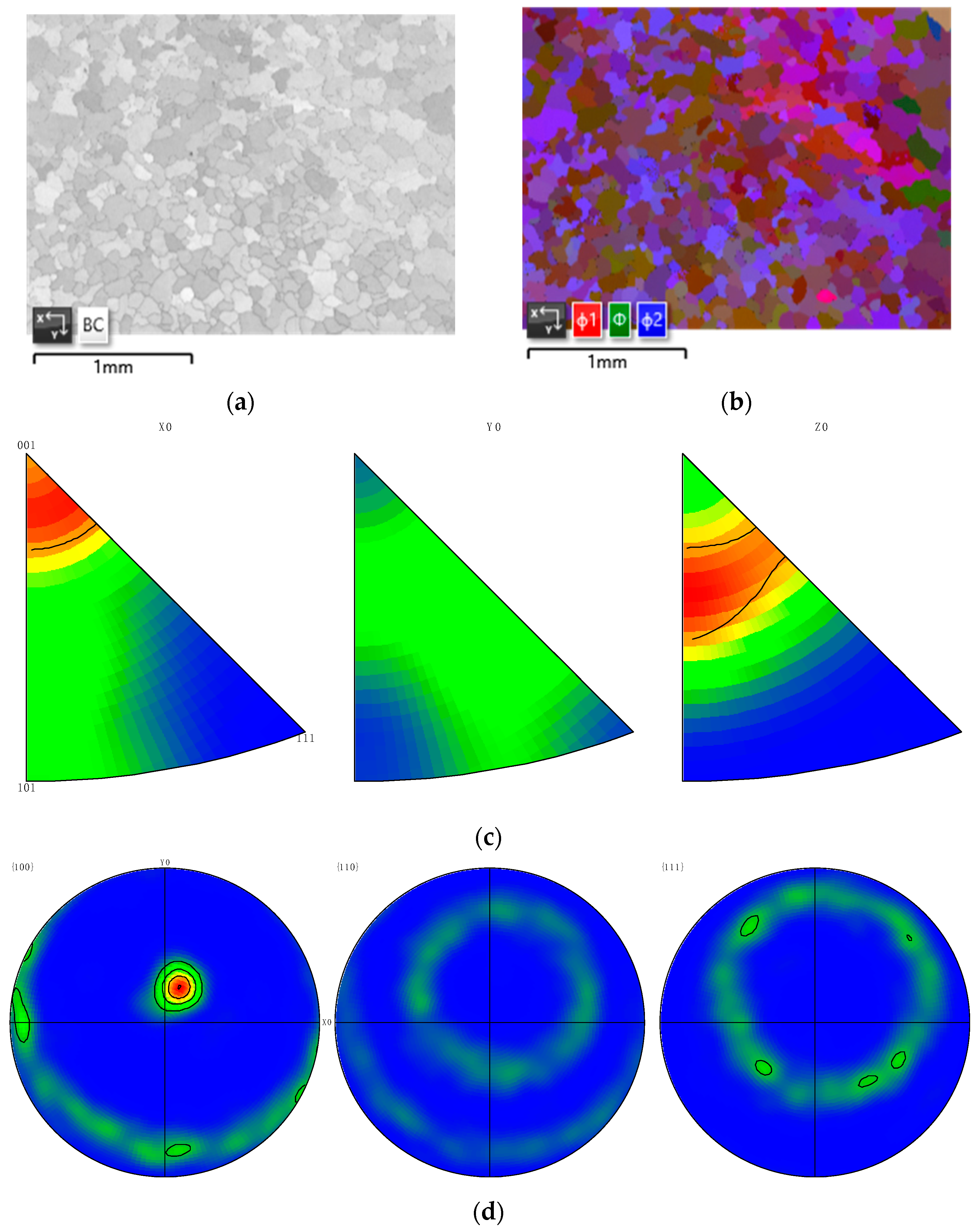
3.1. Composition and Microstructure of Inconel 740H Ni-Based Alloy

The X-ray diffraction (XRD) analysis of the Inconel 740H Ni-based alloy, as depicted in Figure 5, provides valuable insights into its crystalline structure and phase composition. The XRD pattern revealed the distinctive diffraction peaks characteristic of the γ phase, which was the predominant phase in the sample. The γ phase is the face-centered cubic (FCC) crystal structure commonly found in nickel-based superalloys like Inconel 740H. Its presence is indicative of the alloy’s high-temperature stability and excellent mechanical properties, making it suitable for demanding applications in aerospace, gas turbine engines, and other high-temperature environments.
In addition to identifying the primary γ phase, further analysis of the XRD data will involve quantitative phase analysis to determine the relative fractions of different phases present in the sample. This quantitative approach will provide a more comprehensive understanding of the alloy’s phase composition and its potential implications for its mechanical and thermal properties.
Furthermore, analyzing the peak positions and widths in the XRD pattern will enable the extraction of valuable information about the alloy’s crystal structure, including lattice parameters, crystallite size, and any potential presence of residual stresses or texture effects. Understanding these structural characteristics is essential for optimizing the alloy’s performance and designing components with specific mechanical properties.
Comparative analysis of the XRD results with the existing literature on similar Ni-based alloys will further validate our findings and provide valuable context for interpreting the phase composition and crystallographic features observed in the Inconel 740H alloy. This comparison will help elucidate any unique characteristics or deviations from expected phase behavior, guiding future research efforts and alloy development strategies.
In summary, the XRD analysis of the Inconel 740H Ni-based alloy confirms the presence of the γ phase as the main constituent and lays the foundation for a more comprehensive investigation into its phase composition, crystal structure, and mechanical behavior. This expanded analysis will enrich our understanding of the alloy.
The micrographs displayed in Figure 6 and Figure 7 depict various positions of the Inconel 740H Ni-based alloy samples, each revealing distinct microstructural characteristics. In the non-heat-treated sample, the microstructure within the columnar crystal zone exhibited a dendritic morphology comprising primarily the γ phase along with the precipitated phases. Conversely, the remelting zone displayed an equiaxed microstructure consisting of the γ phase along with the precipitated phases. Similarly, the heat-affected zone (HAZ) exhibited an equiaxed microstructure comprising the γ phase and precipitated phases. Notably, no discernible defects such as microcracks were observed in any of the microstructural regions. Upon heat treatment, notable changes were observed in the microstructure of the alloy. Specifically, within the columnar crystal zone, the microstructure transitioned to a γ matrix with precipitated phases. Similarly, the remelting zone exhibited a metallographic structure characterized by a γ matrix with precipitated phases. Likewise, the HAZ displayed a metallographic structure featuring a γ matrix with precipitated phases. This analysis underscores the influence of heat treatment on the microstructural evolution of the Inconel 740H alloy, leading to a transformation in the dominant phases and morphology within different zones of the alloy and the absence of visible defects. Figure 8 shows the low magnification of the heat-treated sample and the sample before heat treatment.
Figure 9 and Figure 10 present EBSD maps illustrating the microstructural evolution of the Inconel 740H alloy before and after heat treatment. Initially, the EBSD diagram of the non-heat-treated alloy displays distinct regions with columnar crystal structures and remelting zones. The columnar crystals are characterized by elongated grain shapes resembling long strips, indicating directional solidification during casting or processing. This directional solidification can result from preferential heat dissipation pathways, leading to aligned grains that may influence mechanical anisotropy and thermal conductivity in the alloy.
In contrast, the remelting zones exhibit equiaxed bulk crystals with a more rounded morphology. These regions likely underwent localized melting followed by rapid solidification, resulting in a more isotropic grain structure. The presence of equiaxed grains can enhance material properties such as ductility and fatigue resistance compared to columnar grains, making them advantageous in applications requiring uniform mechanical performance across different orientations.
Following heat treatment, a significant transformation in microstructure is observed, characterized by an increased predominance of equiaxed bulk crystals. This shift in grain morphology suggests the efficacy of heat treatment in promoting recrystallization and grain growth, which can refine grain boundaries and enhance material properties like toughness and corrosion resistance. The uniform distribution of equiaxed grains also indicates improved microstructural homogeneity, potentially reducing susceptibility to localized stress concentrations and enhancing overall structural integrity.
The polar graphs presented in Figure 9d and Figure 10d underscore the substantial alteration in grain orientation induced by heat treatment. This alteration is manifested by the increased presence of γ’ phase precipitates and intergranular precipitates post heat treatment. The γ’ phase precipitates are known for their role in strengthening nickel-based alloys at elevated temperatures, contributing to improved creep resistance and thermal stability. Intergranular precipitates can also act as barriers against dislocation movement, thereby enhancing the alloy’s mechanical properties under stress.
Moreover, the inverse pole figure and pole figure maps depicted in Figure 9c,d and Figure 10c,d reveal a preferential orientation of alloy crystals toward the (001) plane. This crystallographic orientation is significant as crystals aligned along specific planes often exhibit anisotropic mechanical behavior. The (001) plane orientation, for instance, may confer higher tensile strength and resistance to deformation along certain directions but could also lead to directional weaknesses under specific loading conditions. Managing such crystallographic orientations is crucial in engineering design to optimize material performance across diverse application environments.
In conclusion, the comprehensive EBSD analysis provides profound insights into the microstructural changes induced by heat treatment in the Inconel 740H alloy. These insights are pivotal for tailoring heat-treatment processes to achieve the desired material properties, including enhanced structural stability, mechanical strength, and resistance to environmental degradation. Understanding and optimizing these microstructural transformations are essential for advancing the performance and reliability of nickel-based alloys in demanding industrial sectors such as aerospace, energy production, and automotive engineering.
TEM images were used to further clarify the grain characteristics of the prepared samples, as shown in Figure 11 and Figure 12. The non-heat-treated sample exhibited block and lath morphology (Figure 11a) with inclusions and grain boundary precipitates.
Areas in the non-heat-treated sample where inclusions were observed are shown in Figure 11b,c, and the compositions of these inclusions are reported in Table 3. These inclusions were mostly irregular blocks. EDS analysis showed that these inclusions were composites, and they were mainly composed of titanium and aluminum oxides.
A high-magnification image and corresponding SAED analysis of this intergranular precipitated phase are shown in Figure 9d. The phase of this precipitate was the γ’ phase. Figure 11e shows the massive inclusion found in the non-heat-treated sample. The main elements of this inclusion were Ti, Nb, and N, and the corresponding SAED analysis showed that it exhibited a (Ti, Nb) N phase. This was in good agreement with the results reported in previous studies on the existence of nitrides in Inconel 740H Ni-based alloy [3].
The high-magnification TEM image shown in Figure 11f demonstrates that many dislocations were present in the crystal structure of the non-heat-treated sample. This was due to the high Ni, Cr, and Mo content as well as the high hardening tendency of the Inconel 740H nickel-based alloy. These characteristics meant that defects in the crystal structure (e.g., dislocations and hardened structures) were easily produced. Consequently, the Inconel 740H nickel-based alloy should be heat treated after welding in engineering applications to improve its microstructure and properties. It is generally believed that the existence of dislocations enhances the creep resistance of Inconel 740H [20,21].
TEM images of the heat-treated Inconel 740H Ni-based alloy sample are displayed in Figure 12. A low-magnification TEM image (Figure 12a) demonstrates that many massive carbide and γ’ phase precipitates existed in the grain boundaries and within the alloy after the heat-treatment process. Moreover, the γ’ phase precipitates were smaller than 50 nm. Bright-field and dark-field TEM images of the γ’ phase were obtained, and this phase was analyzed by EDS, as displayed in Figure 12b,c. The elemental compositions of these precipitates are shown in Table 3. Using energy dispersive X-ray spectroscopy (EDS) to detect the elemental composition on the surface or cross-section of samples can achieve a precision of up to 0.01%. Analyzing and processing the spectral data collected from the EDS experiment, we determined the presence and relative content of each element through calibration and peak identification. Data collected from different regions were compared and statistically analyzed to reveal the spatial distribution of elements and compositional changes in the sample. Based on the data analysis results, we ascertained the chemical composition and its distribution before and after heat treatment of the specimen. The γ’ phase had lower Cr and Co content compared with the γ phase. However, the γ’ phase had higher Al, Ti, and Nb content than the γ phase. EDS, SAED, and high-resolution lattice phase analysis of the bulk precipitates at the grain boundaries are shown in Figure 12d,e. These bulk precipitates were mainly composed of Cr23C6 chromium carbides. The crystal plane of these Cr23C6 precipitates was (111). These carbides have a dispersion strengthening effect that improves the high-temperature mechanical performance of the Inconel 740H Ni-based alloy [22,23,24]. Moreover, a comparison of the samples before and after heat treatment shows that the sample dislocations were significantly reduced by heat treatment.
In summary, the Inconel 740H Ni-based alloy samples prepared by wire arc additive manufacturing had a microstructure that mainly consisted of bulk and lath grains. Dislocations, a small amount of oxide inclusions, nitrides, and γ’ phase precipitates were present in the non-heat-treated samples. These oxide inclusions were mainly titanium and aluminum oxides. Heat treatment caused a large number of carbides to precipitate at the grain boundaries, and these carbides were mainly Cr23C6. Moreover, a significant amount of the γ’ phase precipitated in the grains [25].

3.2. Mechanical Properties of Inconel 740H Ni-Based Alloy Sample

The microhardness distributions of the Inconel 740H nickel-based alloy samples are reported in Figure 13. Figure 14 shows the micrograph of the hardness samples before heat treatment at magnifications of 25× and 200×. From Figure 14, the relative distances between each test point can be clearly observed. The transverse microhardness distribution range of the non-heat-treated sample was 285–311 HV0.2, and its average transverse microhardness value was 296.5 HV0.2. The longitudinal microhardness distribution range of this sample was 274–310 HV0.2, and its average longitudinal microhardness value was 290.6 HV0.2. The transverse microhardness distribution range of the heat-treated sample was 352–383 HV0.2, and its average transverse microhardness value was 368.5 HV0.2. The longitudinal microhardness distribution range of this sample was 347–390 HV0.2, and its average longitudinal microhardness value was 367.9 HV0.2. Microhardness was significantly enhanced by heat treatment, with microhardness values showing an improvement of about 70 HV0.2. This was due to the precipitation of carbides and other reinforced phases during the heat-treatment process. Moreover, fluctuations of the longitudinal hardness were more significant than those in the transverse direction. This was because these microhardness fluctuations were mainly caused by changes in the sample microstructure. Figure 1 shows that the formed alloy sample had a multi-layer and multi-pass surface. The microstructure of the first layer’s weld bead was altered by the second layer’s weld bead thermal cycle and the weld bead of the same layer. This led to a columnar crystal zone, a remelting zone, and a HAZ. These regions exhibited varying microhardness values because their microstructures differed (exhibiting different precipitates and grain sizes) [26]. Therefore, the cross-sectional hardness of the samples fluctuated, and fluctuation in the longitudinal direction was greater than that in the transverse direction.
The mechanical properties of the non-heat-treated and heat-treated Inconel 740H Ni-based alloy samples are summarized in Table 4. The room temperature and 600 °C stress–strain curves of these samples are reported in Figure 15. This Inconel 740H alloy exhibited excellent mechanical performance. The strength of this alloy was improved by about 200 MPa via the heat-treatment process. This was because carbide and γ’ equally reinforced phases were precipitated in the sample during heat treatment. In addition, these samples exhibited good mechanical properties at a high temperature of 600 °C, achieving the same performance as that of Inconel 740H after casting, forging, and weldment [27,28,29]. A serrated rheological phenomenon was visible in the tensile stress–strain curves measured at 600 °C. Analysis showed that, at elevated temperatures, the material undergoes microstructural changes, including an increase in dislocation density and alterations in solute atom distribution. These changes exacerbate the effects of dynamic strain aging, leading to more pronounced serrated waves in the stress–strain curve. During dynamic strain aging, stress increases when dislocations are pinned by solute atoms, and decreases rapidly as dislocations overcome the resistance to movement. This cyclic increase and decrease in stress result in serrated waves on the stress–strain curve. The serrated flow effect typically occurs within specific temperature ranges where solute atoms possess sufficient diffusion capability to interact with moving dislocations. The Young’s modulus of each specimen in the experiment varies, as determined through analysis. At different temperatures, the vibration of the lattice in materials changes. Typically, as temperature increases, lattice vibrations strengthen, causing an increase in the average distance between atoms, thereby affecting the material’s elastic modulus. At high temperatures, plastic deformation in the material becomes more pronounced, resulting in changes to the stress–strain curve shape during tensile testing, thereby influencing the Young’s modulus.
The tensile fracture morphology of the non-heat-treated Inconel 740H Ni-based alloy was examined both at room temperature and at 600 °C to elucidate its fracture mechanism, as illustrated in Figure 16. Remarkably, no significant defects were discernible in these samples, aligning well with other findings, notably the higher elongation observed in the tensile sample, as documented in Table 4.
Upon closer examination, Figure 16b,d reveal numerous dimples distributed across the fracture surface when observed at high magnification. This observation strongly suggests that the predominant fracture mechanism exhibited by the Inconel 740H Ni-based alloy is ductile fracture. Dimples, which are characteristic features of ductile fracturing, indicate localized plastic deformation and energy absorption during the fracture process. The presence of dimples further corroborates the alloy’s ability to undergo extensive plastic deformation before failure, highlighting its favorable mechanical properties and ductility.
The absence of significant defects in the samples further underscores the high quality and integrity of the alloy, contributing to its exceptional mechanical performance. This comprehensive analysis of the tensile fracture morphology provides valuable insights into the fracture behavior and mechanical response of the Inconel 740H Ni-based alloy, aiding in the assessment of its suitability for various engineering applications.
Table 5 compares the hardness and tensile properties of Inconel 740H alloy under different manufacturing processes: wire arc additive manufacturing (WAAM), welding, and forging.
For WAAM, the highest hardness after heat treatment reaches approximately 350 HV. The yield strength after heat treatment is 655 MPa, with a tensile strength of 900 MPa and an elongation of 29.5% [4]. For welding, the hardness after heat treatment is around 320 HV, the yield strength is 620 MPa, the tensile strength is 880 MPa, and the elongation ranges from 20% [30]. For forging, the hardness is around 370 HV, the yield strength is around 660 MPa, the tensile strength is 920 MPa, and the elongation of 22% [31]. These results indicate that WAAM has advantages in enhancing the hardness and yield strength of Inconel 740H, especially with appropriate heat treatment. In contrast, welding and forging show slightly better performance in terms of elongation, although they have marginally lower yield and tensile strengths. This comparison helps in evaluating the practicality of using WAAM for manufacturing Inconel 740H components.
The comprehensive data analysis revealed a notable enhancement in both hardness and yield strength of Inconel 740H achieved through wire arc additive manufacturing (WAAM), especially when followed by appropriate heat-treatment protocols. Conversely, traditional methods such as welding and forging exhibit superior elongation characteristics but marginally lower yield and tensile strengths. This detailed comparison underscores the distinct advantages of WAAM in bolstering the mechanical properties of Inconel 740H components, thereby highlighting its potential as a preferred manufacturing technique for this alloy.
Table 5. Performance of Inconel 740H alloy under different manufacturing processes.
Manufacturing ProcessHardness (HV)Yield Strength
(MPa)
Tensile Strength
(MPa)
Elongation (%)Reference
WAAM35065590029.5[32]
Welding32062088020[33]
Forging37066092022[34]

4. Conclusions

An Inconel 740H Ni-based alloy sample was fabricated using wire arc additive manufacturing. This alloy exhibited an excellent forming quality. We have drawn the following conclusions from this study.
  • The non-heat-treated sample exhibited the following microstructures: dendritic γ + precipitated phase in the columnar zone, equiaxed γ + precipitated phase in the remelting zone, and equiaxed γ + precipitated phase in the HAZ. After the solid solution heat-treatment process, the columnar crystal zone had a γ matrix + precipitated phase microstructure, the remelting zone metallographic structure was a γ matrix + precipitated phase, and the HAZ metallographic structure was a γ matrix + precipitated phase. This alloy had a microstructure that was mainly bulk and lath grains.
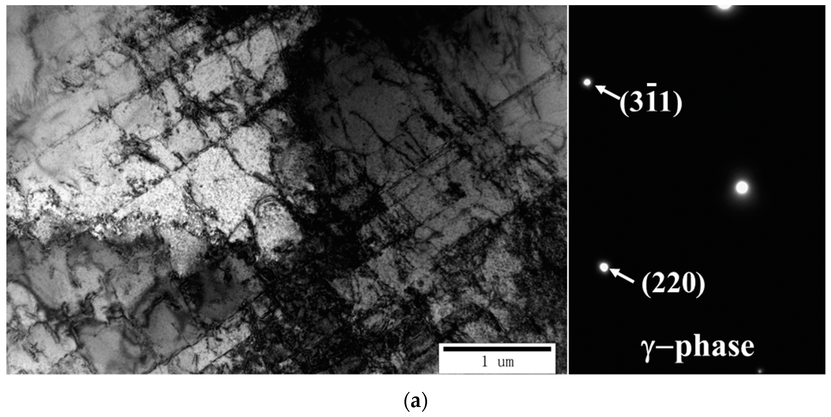
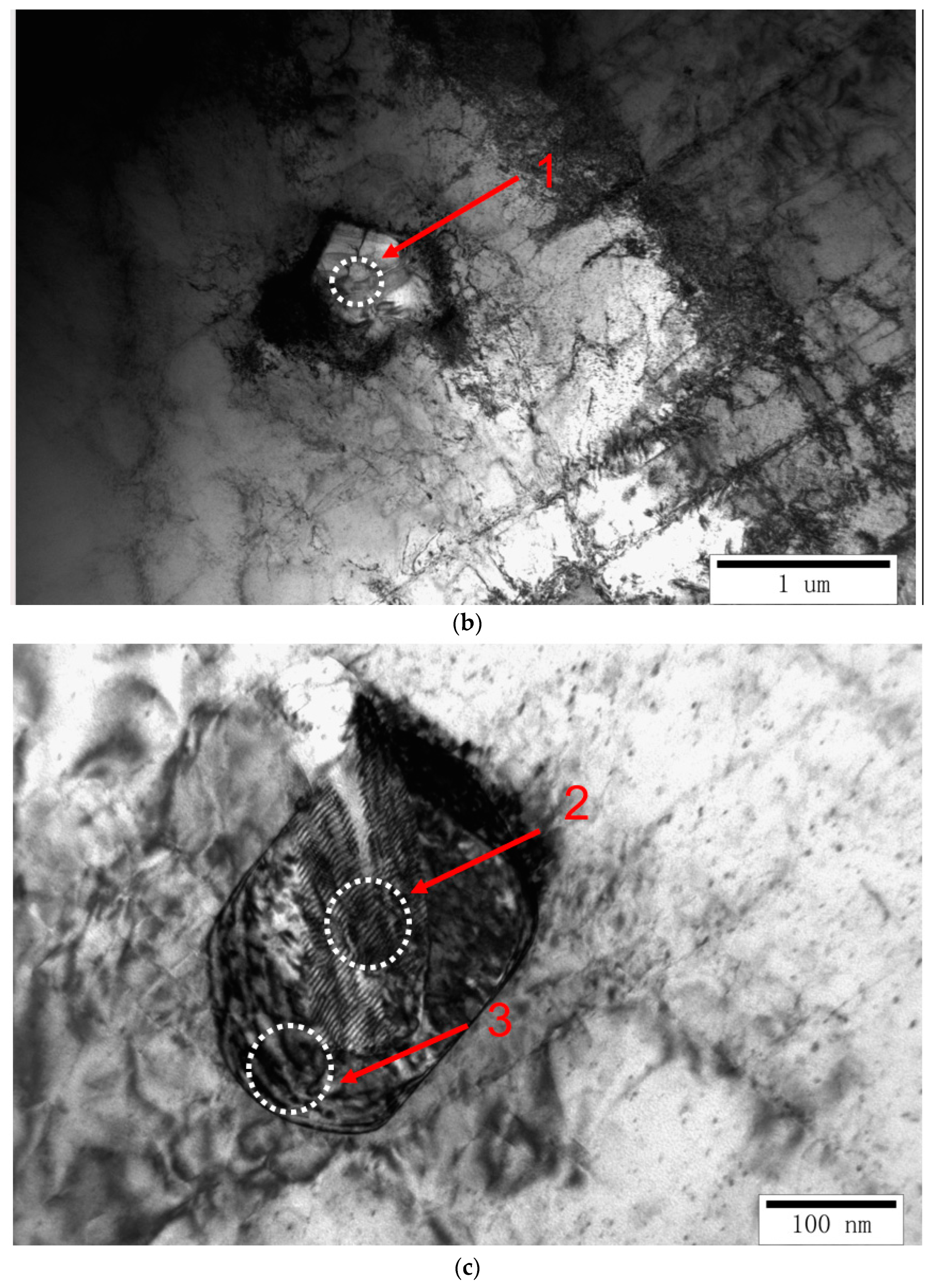
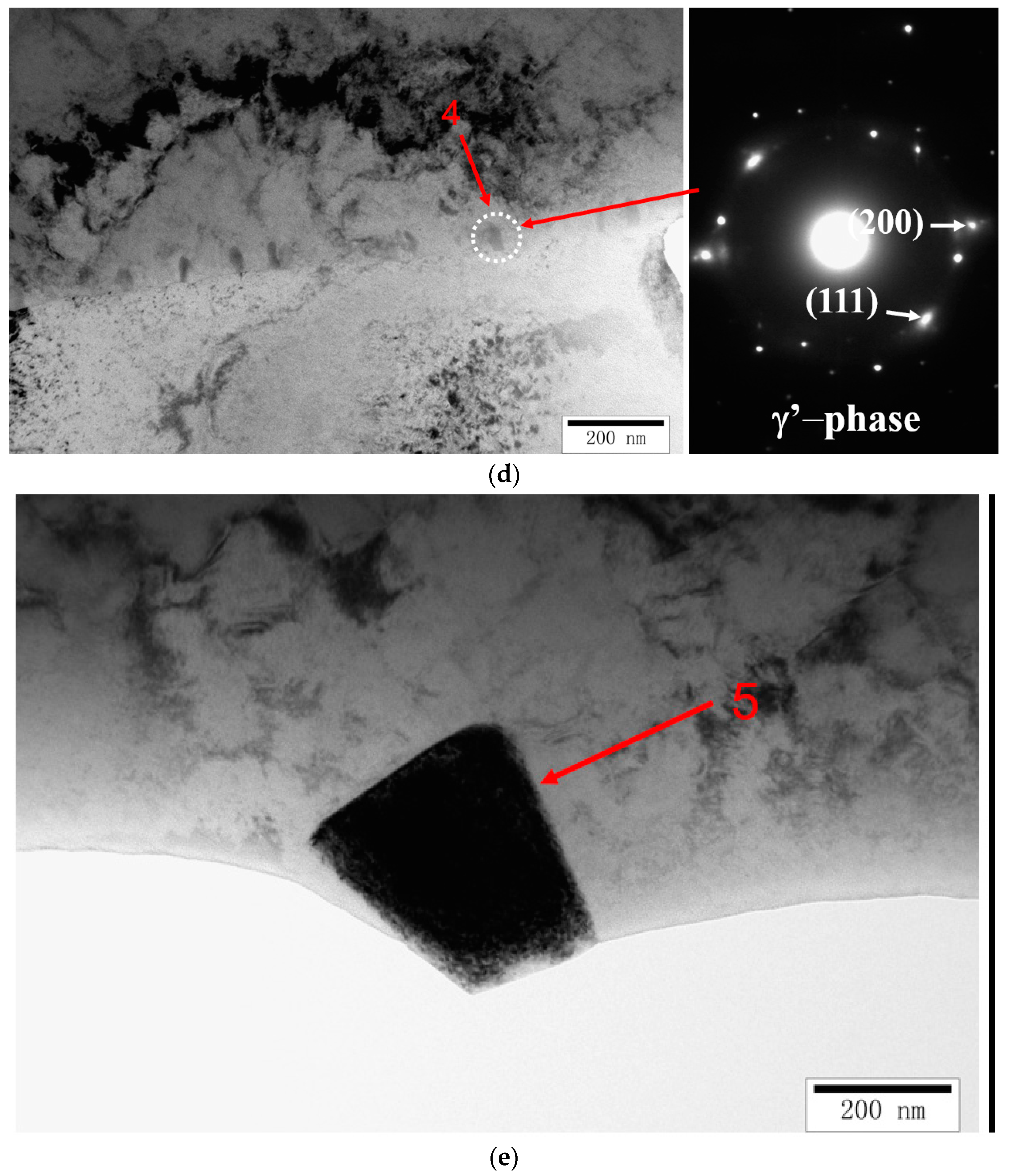
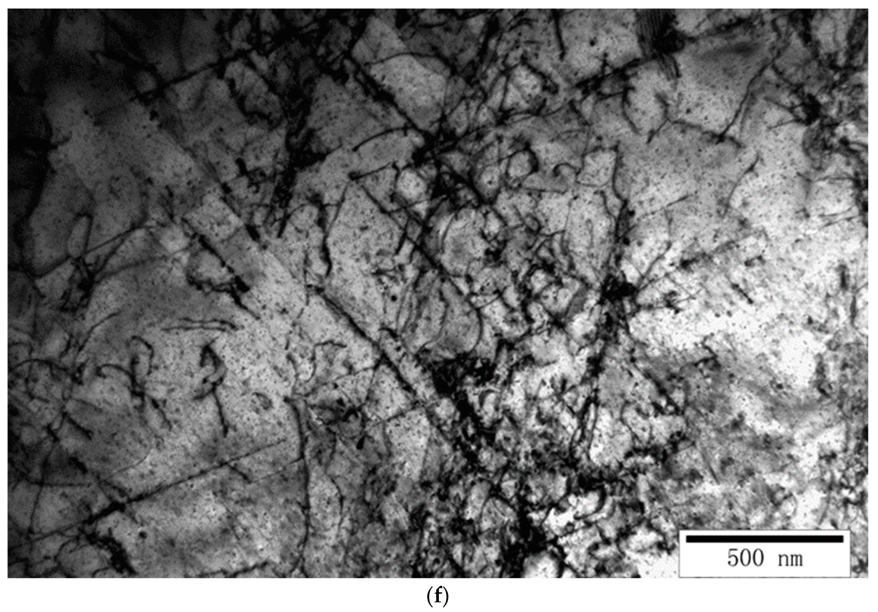
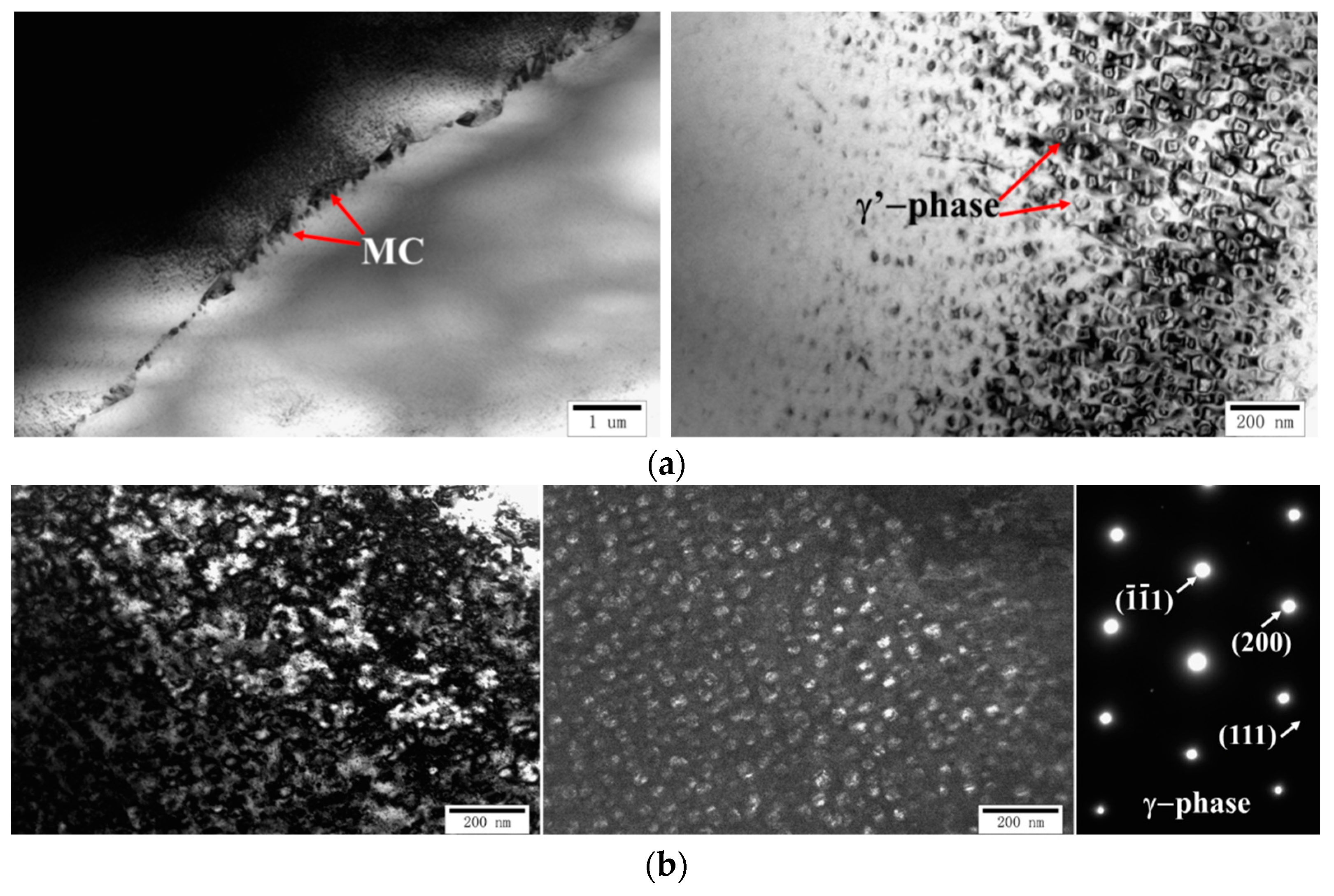
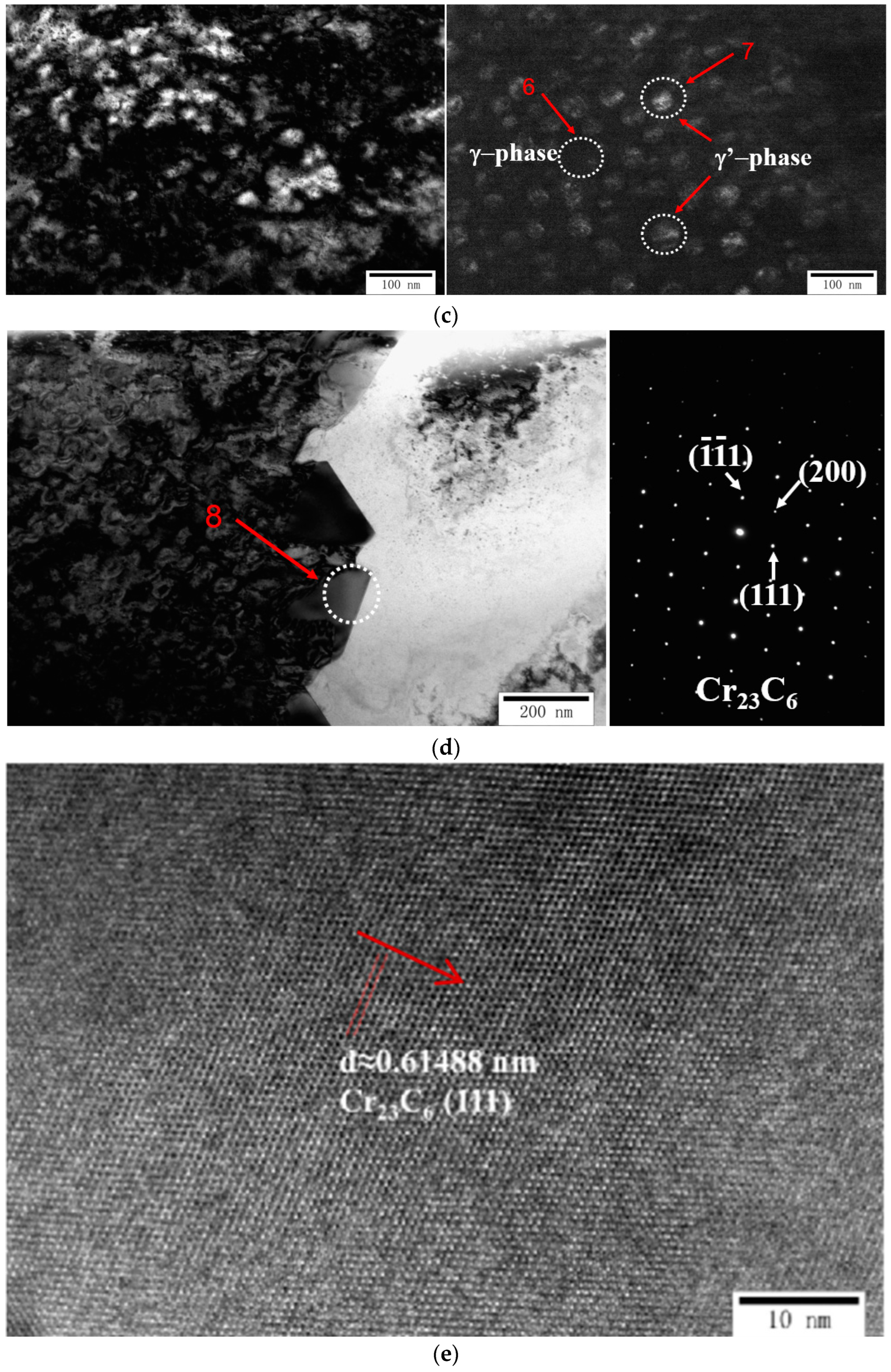
  • Dislocations, a small number of oxide inclusions, nitrides, and γ’ phase precipitates were observed by TEM in the non-heat-treated sample. The oxide inclusions were mainly titanium and aluminum oxides. After heat treatment, many carbides precipitated at the grain boundary, and these carbides mainly exhibited a Cr23C6 phase. Moreover, a significant amount of γ’ phase precipitated in the grains.
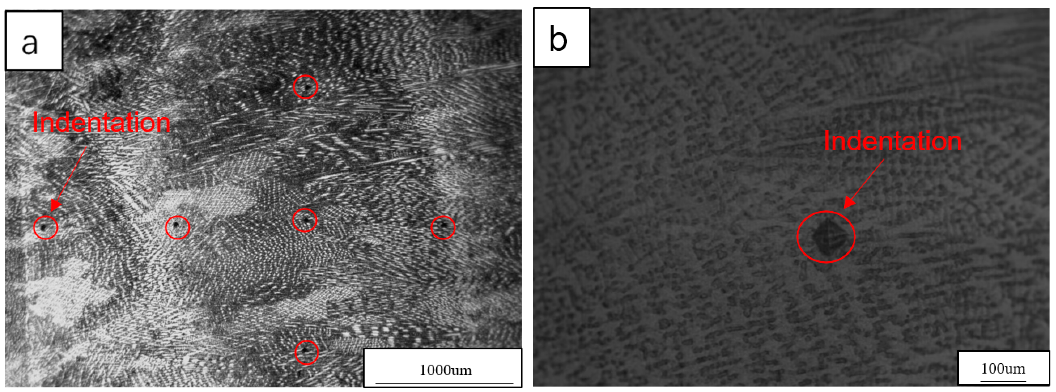
  • The transverse microhardness distribution range of the non-heat-treated Inconel 740H Ni-based alloy was 285–311 HV0.2, and the average value was 296.5 HV0.2. The longitudinal microhardness distribution range of this sample was 274–310 HV0.2, and the average value was 290.6 HV0.2. The transverse microhardness distribution range of the heat-treated Inconel 740H Ni-based alloy was 352–383 HV0.2, and the average value was 368.5 HV0.2. The longitudinal microhardness distribution range of this sample was 347–390 HV0.2, and the average value was 367.9 HV0.2.
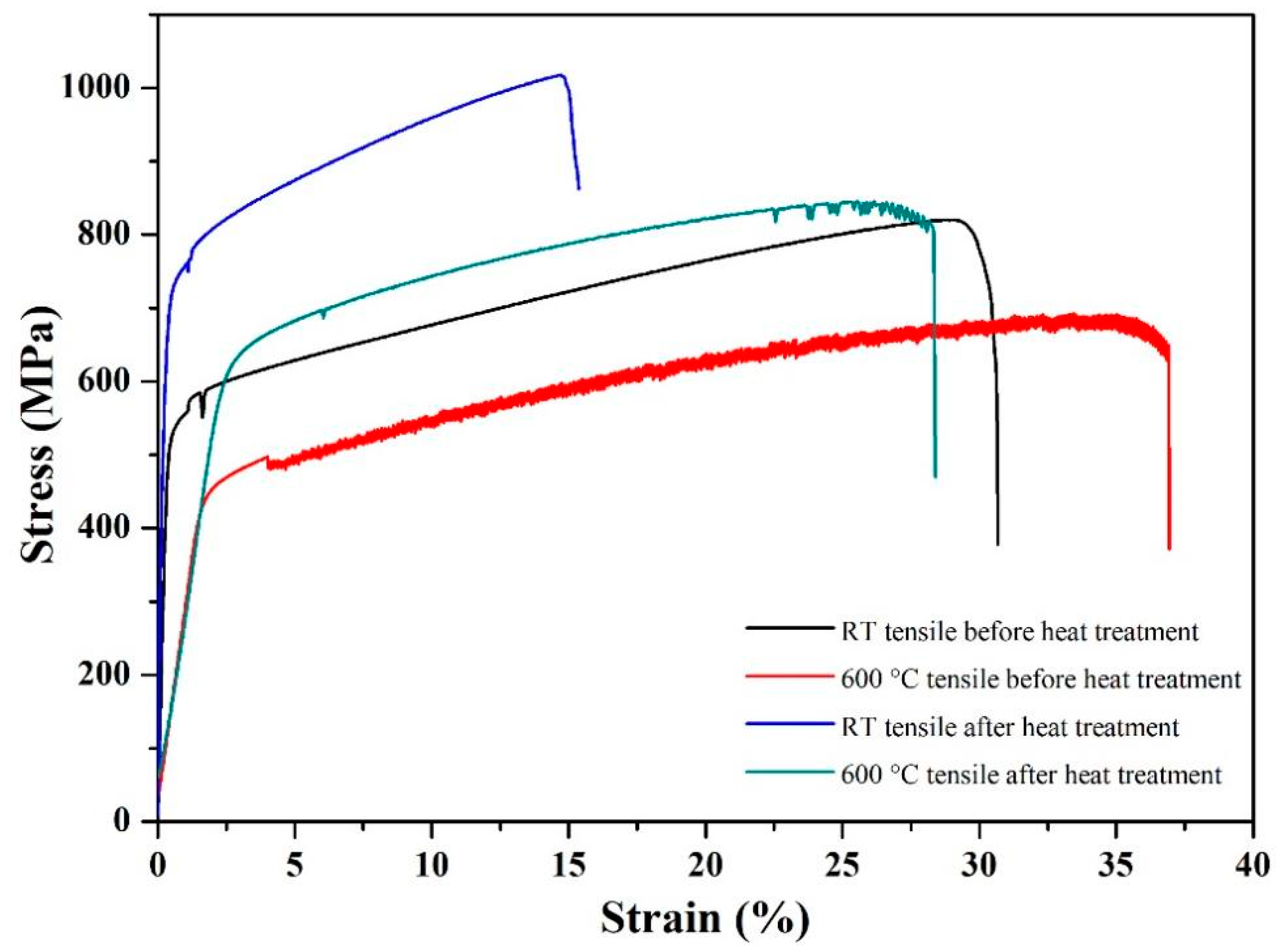
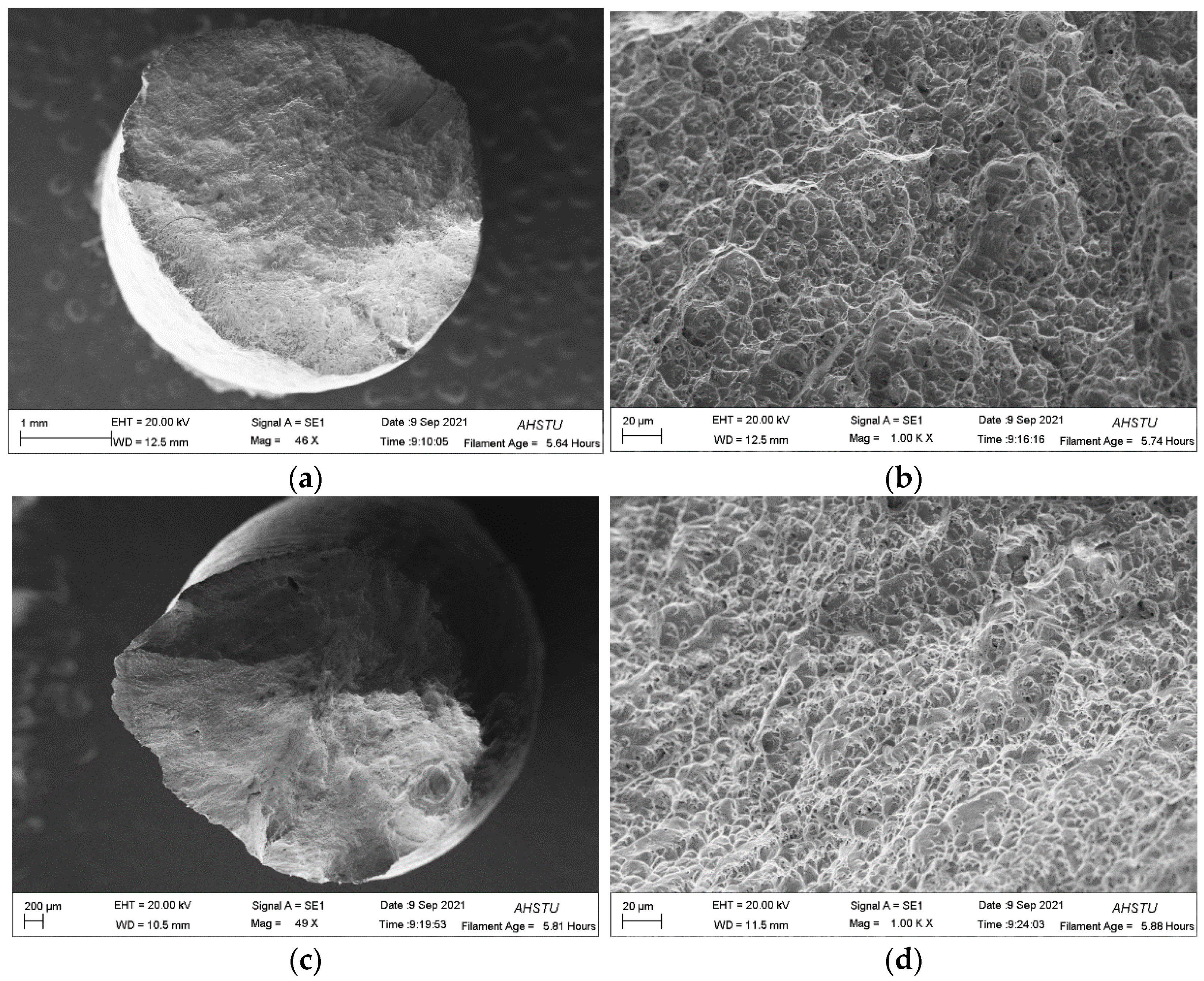
  • The mechanical performance of these samples was excellent: at room temperature; the non-heat-treated sample had yield strength, tensile strength, elongation, and average Charpy impact values of 529 MPa, 820 MPa, 24%, and 129.7 J. At 600 °C, this sample had yield strength, tensile strength, and elongation values of 441 MPa, 692 MPa, and 38.5%. After heat treatment, the sample had room-temperature yield strength, tensile strength, elongation, and average Charpy impact values of 710 MPa, 1018 MPa, 17.5%, and 74 J. At 600 °C, a tensile strength of 846 MPa and an elongation of 22.5% were exhibited by the heat-treated sample. This heat-treatment process improved the sample strength by about 200 MPa, leading to better high-temperature mechanical properties. This work is anticipated to offer theoretical and experimental support for the use of additive manufacturing methods in the manufacturing of nickel-based superalloy components.

Author Contributions

Conceptualization, C.G.; methodology, C.G.; software, W.L.and G.H.; validation, W.L.and Q.L.; formal analysis, W.L.; investigation, R.H.and G.H.; resources, C.G.; data curation, C.G.; writing—original draft preparation, R.H.and X.Z.; writing—review and editing, G.H.; visualization, X.Z. and Q.L.; supervision, C.G.; project administration, C.G.; funding acquisition, C.G. All authors have read and agreed to the published version of the manuscript.

Funding

This research was funded by the Foundation of Colleges and Universities in Anhui Province (2023AH040273), Excellent top talent project in Colleges and Universities (gxbjZD2022046), the University Synergy Innovation Program of Anhui Province (GXXT-2023-025, GXXT-2023-026), Anhui Province Graduate Education Quality Engineering Project (2023lhpysfjd057, 2023xscx135, 2023xscx136), Reserve candidates for academic and technical leaders of Anhui Science and Technology University (202101), College major subject of Anhui Science and Technology University (XK-XJJC002), Foundation of Colleges and Universities in Anhui Province (YJS20210558, KJ2020A0073), Talent program of Anhui Science and Technology University (RCYJ201905), Anhui Provincial Natural Science Foundation (1908085QE174, 2108085ME167), Ministry Equipment Pre-Research Project Foundation of China (61409230612), and Action Discipline (Professional) Leader Training Project for Middle and Young Teachers of Anhui Province: (DTR2023085) for financial support.

Data Availability Statement

The data presented in this study are available on request from the corresponding author. The data are not publicly available due to privacy.

Conflicts of Interest

The authors declare no conflicts of interest.

References

  1. Zhang, S.; Takahashi, Y. Creep-fatigue life and damage evaluation under various strain waveforms for Ni-based Alloy 740H. Int. J. Fatigue 2023, 176, 107833. [Google Scholar] [CrossRef]
  2. Sridar, S.; Wang, X.; Shabani, M.; Klecka, M.A.; Xiong, W. Design of Graded Transition Interlayer for Joining Inconel 740H Superalloy with P91 Steel Using Wire-Arc Additive Manufacturing. In Proceedings of the 10th International Symposium on Superalloy 718 and Derivatives; Springer: Berlin/Heidelberg, Germany, 2023; pp. 755–772. [Google Scholar]
  3. Sridar, S.; Ladinos Pizano, L.F.; Klecka, M.A.; Xiong, W. Achieving High Strength and Creep Resistance in Inconel 740H Superalloy through Wire-Arc Additive Manufacturing and Thermodynamic-Guided Heat Treatment. Materials 2023, 16, 6388. [Google Scholar] [CrossRef]
  4. Sridar, S.; Klecka, M.A.; Xiong, W. Interfacial characteristics of P91 steel-Inconel 740H bimetallic structure fabricated using wire-arc additive manufacturing. J. Am. Acad. Dermatol. 2022, 300, 117396. [Google Scholar] [CrossRef]
  5. Render, M.; Santella, M.L.; Chen, X.; Tortorelli, P.F.; Cedro, V. Long-term creep-rupture behavior of alloy Inconel 740/740H. Metall. Mater. Trans. A 2021, 52, 2601–2612. [Google Scholar] [CrossRef]
  6. Kim, D.-M.; Kim, C.; Yang, C.-H.; Park, J.-U.; Jeong, H.-W.; Yim, K.-H.; Hong, H.-U. Heat treatment design of Inconel 740H superalloy for microstructure stability and enhanced creep properties. J. Alloy Compd. 2023, 946, 169341. [Google Scholar] [CrossRef]
  7. Shingledecker, J.; Griscom, E.; Bridges, A. Relationship between Grain Size and Sample Thickness on the Creep-Rupture Performance of Thin Metallic Sheets of INCONEL Alloy 740H. J. Mater. Eng. Perform. 2023, 32, 9309–9322. [Google Scholar] [CrossRef]
  8. Xiao, B.; Zhang, N.; Li, K.; Zhu, Z.; Zhang, T.; Zhou, M. Corrosion behaviour of Ni-based alloy Inconel 740H in supercritical carbon dioxide at 650-700° C. Corros. Eng. Sci. Technol. 2023, 58, 180–189. [Google Scholar] [CrossRef]
  9. Zhu, J.-Q.; Lu, Y.-X.; Sun, L.-G.; Huang, S.; Mei, L.-B.; Zhu, M.-L.; Xuan, F.-Z. Effect of microstructure on fatigue resistance of Inconel 740H and Haynes 282 nickel-based alloys at high temperature. Mater. Charact. 2023, 203, 113095. [Google Scholar] [CrossRef]
  10. Shingledecker, J.; Siefert, J.; Lolla, T.; Dupont, J.; deBarbadillo, J.; Gollihue, R. Factors Influencing Propensity for Stress Relaxation Cracking in Inconel® Alloy 740H® and Practical Guidance for Applications. In Proceedings of the 10th International Symposium on Superalloy 718 and Derivatives; Springer: Berlin/Heidelberg, Germany, 2023; pp. 431–443. [Google Scholar]
  11. Cheng, J.; Hu, X.; Lach, T.; Chen, X. Crystal plasticity modeling and analysis for the transition from intergranular to transgranular failure in nickel-based alloy Inconel 740H at elevated temperature. Mater. Sci. Eng. A 2024, 902, 146622. [Google Scholar]
  12. Guo, C.; Liu, S.; Hu, R.; Liu, C.; Chen, F. Microstructure and properties of a 2.25 Cr1Mo0. 25V heat-resistant steel produced by wire arc additive manufacturing. Adv. Mater. Sci. Eng. 2020, 2020, 1–9. [Google Scholar]
  13. de Vidales, M.J.M.; Nieto-Márquez, A.; Morcuende, D.; Atanes, E.; Blaya, F.; Soriano, E.; Fernández-Martínez, F. 3D printed floating photocatalysts for wastewater treatment. Catal. Today 2019, 328, 157–163. [Google Scholar] [CrossRef]
  14. Gang, C.; Zhao, S.-y.; Ping, T.; Yin, J.-o.; Quan, Z.; Yuan, G.; Li, Z.-f.; Jian, W.; Tang, H.-p.; Peng, C. Shape memory TiNi powders produced by plasma rotating electrode process for additive manufacturing. Trans. Nonferrous Met. Soc. China 2017, 27, 2647–2655. [Google Scholar]
  15. Giannopoulos, A.A.; Mitsouras, D.; Yoo, S.-J.; Liu, P.P.; Chatzizisis, Y.S.; Rybicki, F.J. Applications of 3D printing in cardiovascular diseases. Nat. Rev. Cardiol. 2016, 13, 701–718. [Google Scholar] [CrossRef] [PubMed]
  16. Martin, J.H.; Yahata, B.D.; Hundley, J.M.; Mayer, J.A.; Schaedler, T.A.; Pollock, T.M. 3D printing of high-strength aluminium alloys. Nature 2017, 549, 365–369. [Google Scholar] [CrossRef] [PubMed]
  17. Xiao, D.; Jing, H.; Xu, L.; Zhao, L.; Han, Y. Microstructure and Damage Evolution of Inconel 740H Welded Joint during Creep Process at 750° C. J. Mater. Eng. Perform. 2021, 30, 4562–4571. [Google Scholar] [CrossRef]
  18. Zhang, Y.; Zhang, F.; Yan, Z.; Ma, Q.; Li, X.; Huang, Y.; Rogers, J.A. Printing, folding and assembly methods for forming 3D mesostructures in advanced materials. Nat. Rev. Mater. 2017, 2, 1–17. [Google Scholar] [CrossRef]
  19. Rashid, M.; Sabu, S.; Kunjachan, A.; Agilan, M.; Anjilivelil, T.; Joseph, J. Manufacture. Advances in Wire-Arc Additive Manufacturing of Nickel-Based Superalloys: Heat Sources, DfAM Principles, Material Evaluation, Process Parameters, Defect Management, Corrosion Evaluation and Post-Processing Techniques. Int. J. Light. Mater. Manuf. 2024, 32, 144342. [Google Scholar]
  20. Guguloth, K.; Roy, N. Study on the creep deformation behavior and characterization of 9Cr-1Mo-V-Nb steel at elevated temperatures. Mater. Charact. 2018, 146, 279–298. [Google Scholar] [CrossRef]
  21. Watanabe, T.; Tabuchi, M.; Yamazaki, M.; Hongo, H.; Tanabe, T. Creep damage evaluation of 9Cr–1Mo–V–Nb steel welded joints showing Type IV fracture. Int. J. Press. Vessel. Pip. 2006, 83, 63–71. [Google Scholar] [CrossRef]
  22. Kościelniak, B.; Chmiela, B.; Sozańska, M.; Swadźba, R.; Drajewicz, M. Oxidation Behavior of Inconel 740H Nickel Superalloy in Steam Atmosphere at 750° C. Materials 2021, 14, 4536. [Google Scholar] [CrossRef]
  23. Ji, L.; Liying, T.; Jiang, L.; Rongcan, Z.; Li, Z.; Weiguo, L.; Xiaomin, L. Study on the Performance Evolution of Inconel 740H During Operation on the Key Component Test Facility at 700 degrees C. Rare Met. Mater. Eng. 2021, 50, 3304–3312. [Google Scholar]
  24. Bolton, J. Rupture modelling and extrapolation of a sparse dataset for Inconel 740H. Int. J. Press. Vessel. Pip. 2021, 194, 104543. [Google Scholar] [CrossRef]
  25. Lee, S.-Y.; Kim, B.-K.; Lee, S.-H.; Kim, D.-I.; Shim, J.-H.; Jung, W.-S.; Suh, J.-Y. Formation of needle-like MC carbide at or near incoherent twin boundary in IN740H Ni-based superalloy. J. Alloy Compd. 2020, 813, 152222. [Google Scholar] [CrossRef]
  26. Zhang, X.; Liu, R.; Wu, X.; Wu, X.; Khelfaoui, F. Microstructure and Hardness Investigation of Tribaloy Alloy T-400C Hardfacing Deposited on Nickel-Based Alloy Inconel 740H via Plasma Transferred Arc Welding Subjected to Long-Time Aging. Met. Microstruct. Anal. 2024, 13, 145–173. [Google Scholar] [CrossRef]
  27. Lu, X. Multi-scale study of hydrogen-assisted cracking in nickel-based superalloys. NTNU 2020, 32, 123511. [Google Scholar]
  28. Parnaik, A.; Pavan, A.; Silchonok, S.; Kislov, N.; Narayan, R. High-cycle fatigue behavior of Haynes 282 superalloy subjected to accelerated ageing. Int. J. Fatigue 2024, 182, 108234. [Google Scholar] [CrossRef]
  29. Sroka, M.; Zieliński, A.; Śliwa, A.; Nabiałek, M.; Kania-Pifczyk, Z.; Vasková, I. The Effect of Long-Term Ageing on the Degradation of the Microstructure the Inconel 740h Alloy. Acta Phys. Pol. A 2020, 137, 355–360. [Google Scholar] [CrossRef]
  30. Jin, W.; Zhang, C.; Jin, S.; Tian, Y.; Wellmann, D.; Liu, W. Wire arc additive manufacturing of stainless steels: A review. Appl. Sci. 2020, 10, 1563. [Google Scholar] [CrossRef]
  31. Kumar, C.; Kumar, P. Analyzing dynamic strain aging and yield strength anomaly in IN740H, a nickel-based superalloy comprising low volume fraction of γ′. Materialia 2024, 33, 102028. [Google Scholar] [CrossRef]
  32. Yangfan, W.; Zhang, C.; Chuanchu, S. Microstructure and mechanical properties of Inconel 625 fabricated by wire-arc additive manufacturing. Surf. Coat. Technol. 2019, 374, 116–123. [Google Scholar] [CrossRef]
  33. Athira, K.S.; Chatterjee, S. Effect of keyhole gas tungsten arc welding and post-welding heat treatment on microstructure and hardness of inconel 740H. J. Mater. Eng. Perform. 2023, 1–15. [Google Scholar] [CrossRef]
  34. Song, R.-H.; Qin, H.-L.; Li, D.-F.; Bi, Z.-N.; Busso, E.P.; Yu, H.-Y.; Liu, X.-L.; Du, J.-H.; Zhang, J. An Experimental and Numerical Study of Quenching-Induced Residual Stresses under the Effect of Dynamic Strain Aging in an IN718 Superalloy Disc. J. Eng. Mater. Technol. 2022, 144, 011002. [Google Scholar] [CrossRef]
Figure 1. Schematic of the printing path: (a) Odd-level printing path, (b) Even-level printing path.
Metals 14 00809 g001
Figure 2. Photograph of Inconel 740H nickel-based alloy thin-wall sample.
Metals 14 00809 g002
Figure 3. Schematic diagram of the Inconel 740H nickel-based alloy sampling location.
Metals 14 00809 g003
Figure 4. Dimensions of the tensile specimen diagram (unit: mm).
Metals 14 00809 g004
Figure 5. XRD pattern of Inconel 740H nickel-based alloy prepared by wire arc additive manufacturing before the heat affect.
Metals 14 00809 g005
Figure 6. Micrograph photos displaying the microstructures of the as-prepared Inconel 740H Ni-based alloy sample before heat treatment: (a,b) the columnar crystal zone, (c,d) the remelting zone, and (e,f) the heat-affected zone.
Metals 14 00809 g006
Figure 7. Micrographs displaying the microstructures of the heat-treated Inconel 740H Ni-based alloy sample: (a,b) the columnar crystal zone, (c,d) the remelting zone, and (e,f) the heat-affected zone.
Metals 14 00809 g007
Figure 8. Low magnification of microstructure of Inconel 740H nickel-based alloy: (a) heat-treated Inconel 740H Ni-based alloy sample, (b) Inconel 740H Ni-based alloy sample before heat treatment.
Metals 14 00809 g008
Figure 9. EBSD analysis of the as-prepared Inconel 740H nickel-based alloy sample before heat treatment: (a) image quality map, (b) Euler angle color map, (c) inverse pole figure map, and (d) pole figure map.
Metals 14 00809 g009
Figure 10. EBSD analysis of heat-treated Inconel 740H nickel-based alloy sample: (a) image quality map, (b) Euler angle color map, (c) inverse pole figure map, and (d) pole figure map.
Metals 14 00809 g010
Figure 11. TEM images of Inconel 740H Ni-based alloy sample before heat treatment: (a) low-magnification TEM image of sample and SAED pattern, (b,c) inclusions and EDS analysis, (d) γ’ phase and SAED pattern, (e) nitride inclusion and EDS analysis, and (f) TEM images. 1–5 is the region where the chemical composition of the sample is detected.
Metals 14 00809 g011aMetals 14 00809 g011bMetals 14 00809 g011cMetals 14 00809 g011d
Figure 12. TEM images of Inconel 740H Ni-based alloy sample after heat treatment: (a) low-magnification image of MC and γ’ phase, (b) bright-field and dark-field images with SAED pattern, (c) bright-field and dark-field images with EDS analysis, (d) Cr23C6–precipitate, and (e) HRTEM image. 6–8 is the region where the chemical composition of the sample is detected.
Metals 14 00809 g012aMetals 14 00809 g012b
Figure 13. Microhardness distributions of the Inconel 740H sample before and after heat treatment.
Metals 14 00809 g013
Figure 14. Micrographs of hardness samples at 25× and 200× before heat treatment: (a) micrographs of hardness samples at 25× before heat treatment; (b) micrographs of hardness samples at 200× before heat treatment.
Metals 14 00809 g014
Figure 15. Stress–strain curves of non-heat-treated and heat-treated Inconel 740H Ni-based alloy samples obtained at room temperature and 600 °C.
Metals 14 00809 g015
Figure 16. Tensile fracture morphology of the Inconel 740H Ni-based alloy sample before heat treatment: (a,b) the room temperature tensile fracture morphology and (c,d) the 600 °C tensile fracture morphology.
Metals 14 00809 g016
Table 1. Inconel 740H solid wire chemical composition (wt%).
SampleCSiMnNiCrCoTiAlNb + TaMo
740H0.030.10.2449.4824.620.31.51.41.490.5
Table 2. Wire arc additive manufacturing process parameters.
SampleVoltage/VCurrent/AWire Feed Speed/m·min−1Printing Speed/m·s−1Contact Tip to
Work Distance/mm
Shielding Gas Flow/L·min−1Interpass Temperature/°COverlap Rate/%
Inconel 740H2010051510–2015–20 15050
Table 3. Chemical compositions of the precipitates detected in the Inconel 740H Ni-based samples before and after heat treatment.
Analyzed PrecipitateChemical Composition (wt%)
NiCrCoTiAlNbMoMgCNO
Inclusions (1)0.551.120.2629.199.095.90-4.51-11.1738.21
Inclusions (2)1.102.660.4969.22-6.62---19.92-
Inclusions (3)0.521.220.4515.6726.061.32-10.24--44.53
γ’ phase (4)30.6249.6317.09-2.66------
Nitride (5)1.302.150.5749.35-5.63---41-
γ phase (6)44.4829.0723.800.572.07------
γ’ phase (7)55.4412.2910.505.219.626.94
Cr23C6 (8)4.5963.983.74---2.11-25.58--
Table 4. Inconel 740H Ni-based alloy mechanical properties before and after heat treatment.
SampleTest TemperatureYield
Strength
/MPa
Tensile Strength/MPaElongation (%)RT Impact Toughness/J
Before heat treatmentRoom temperature52982024129 ± 6.78
600 °C44169238.5
After heat treatmentRoom temperature710101817.574 ± 6.32
600 °C61484622.5
Inconel 740HRoom temperature31379657-
Disclaimer/Publisher’s Note: The statements, opinions and data contained in all publications are solely those of the individual author(s) and contributor(s) and not of MDPI and/or the editor(s). MDPI and/or the editor(s) disclaim responsibility for any injury to people or property resulting from any ideas, methods, instructions or products referred to in the content.

