Abstract
Since F/M steel is one of the leading candidate materials for the lead-cooled fast reactor (LFR), its compatibility with the liquid LBE environment is an essential issue before application. One major way to improve LBE corrosion resistance is to control the oxygen concertation in liquid LBE for the growth of a stable, protective oxide layer on the surface of the structure material. However, the influence of the surface state on corrosion behavior is a more realistic issue when it comes to practical applications. In this study, the corrosion behavior of Si-reinforced 9Cr and 11Cr F/M steels with different surface states was investigated by a static liquid LBE corrosion test under solid-phase oxygen-controlled conditions. The result showed that at 550 °C, the coarse surface state caused dissolution behavior at the initial stage of corrosion, while the fine surface state formed the oxide layer. Moreover, at 610 °C, Si-reinforced 11Cr F/M steel shows better liquid LBE corrosion resistance due to its thinner oxide layer formation.
1. Introduction
The Lead-cooled fast reactor (LFR) is one of the most promising fourth-generation reactors, and Pb-Bi eutectic (LBE) is the most preferred coolant for LFR due to its low melting point (125 °C), high boiling point (1670 °C), chemical inertness, and good neutron economy, etc. The designed service temperature of LFR is up to 550 °C, and the structural materials are facing damage problems, such as fast neutron irradiation, liquid LBE corrosion, and liquid metal embrittlement (LME). In particular, the core structural materials are required to withstand irradiation damage of 50–150 dpa and have good long-time thermal aging mechanical properties, such as tensile strength, plasticity, fracture toughness, creep, and fatigue. Also, it is required to have good compatibility with the liquid LBE environment and low activation [1,2,3]. Therefore, the structural material has become a bottleneck in the R&D and application of LFRs. Recently, Gong et al. [3] have systematically reviewed the candidate structural materials and their liquid LBE environmental compatibility for LFRs. They pointed out that ferrite/martensitic (F/M) steels, austenitic stainless steels, oxide dispersion strengthened steels, refractory metals, SiC fiber-reinforced SiC matrix composites, and the MAX phases are the main candidate materials. Among them, F/M steels and austenitic stainless steels are structural materials that have been used in nuclear areas in large quantities, with a large amount of in-service performance data accumulated and included in relevant manuals, such as those of the American Society of Mechanical Engineers (ASME). Those materials are the most likely structural materials to be used in LFRs. Therefore, the liquid LBE corrosion of F/M steels and austenitic stainless steels has become the focus of domestic and international research.
Until now, two main corrosion reduction methods have been investigated. One is to apply anti-corrosion coatings or surface alloying to the material’s surface [4,5,6,7,8,9,10,11,12,13,14,15,16,17], and the other is to control the oxygen concentration of liquid LBE to form a stable oxide layer on the steel surface to protect the structural material. The solubility of metal oxides is much lower than that of Fe-based alloy elements, which further prevents dissolution corrosion from occurring to ensure the long service life of the material [18,19,20]. To form a stable oxide layer, sufficient oxygen in LBE is needed to form the magnetite oxide layer. However, if the oxygen concentration is too high, not only will the oxide layer of the structural material corrode and flake off, thus reducing the service life, but it will also cause significant problems such as pipeline blockage due to the deposition of impurities, such as generated PbO and flaked magnetite. Therefore, the oxygen concentration in liquid LBE needs to be controlled in a suitable range, that is, to ensure that the generated oxide film is not destroyed and no oxide impurities are generated [21,22]. According to Ellingham’s diagram, the oxygen concentration in liquid LBE should be chosen to ensure that magnetite can be generated on the surface of the iron-based structural material as well as to ensure that PbO is not generated, which depends on the specific operation temperature but is generally controlled at 10−8–10−6 wt.% [3,23].
Meanwhile, alloying is also an effective way to improve the LBE corrosion resistance of structural materials. The generation of Si or Al-rich oxides through the addition of elements such as Si and Al to improve the densification of the oxide film and the bonding of oxide film to the substrate has become a popular method to improve the liquid LBE corrosion resistance of F/M steels and stainless steels [24,25,26,27,28,29,30,31,32,33,34,35,36,37,38,39]. However, Si addition promotes the formation of harmful phases and reduces the mechanical properties of the alloys. Chen and Rong [40] showed that the increase in Si content leads to the precipitation of the Leaves phase in F/M steels and, therefore, raises the ductile–brittle transition temperature (DBTT). Van Den Bosch et al. [41] showed that Si addition increases the LME sensitivity of F/M steels. Gong et al. [42] combined experiments with first-principle calculations to reveal the mechanism by which Si addition increases the LME sensitivity of pure Fe with bcc structure. Therefore, the current research and development of Si addition alloys is mainly aimed at enhancing the corrosion resistance of alloys to liquid LBE.
However, the effect of the surface state of the sample on the application of the material in LBE was still unclear. Ilinčev et al. [43] showed the differences in the LBE corrosion behavior of approximately 20 types of structural steels (austenitic, ferritic, and martensitic) under three different surface conditions: ground, passivated, and as-produced. Their result showed that the passivation has a positive effect for these materials after a 1000 h LBE corrosion test at 500 °C with an oxygen content of 3–4 × 10⁻⁶ wt.% and 2 × 10⁻⁵ wt.%. Martín-Muñoz et al. [44] showed that surface finishes (as-machined; ground; ground and polished; electropolished) of T91 (F/M steel) and 316L (austenitic stainless steel) steel have no significant effect on the corrosion/protection processes after a 2000 h LBE corrosion test at 775 K and 825 K under an oxygen control condition via gas phase. Wang et al. [45] showed that the shot peening process on the surface of 15–15Ti austenitic steel can improve the resistance to oxidation and intergranular cracking under oxygen-controlled static liquid LBE at 550 °C. Therefore, it is essential to carry out this study of the effect of the surface state of F/M steels, which is used as a structural material for LFR, on the corrosion behavior of the material in an oxide-controlled LBE environment. In this study, two types of Si-reinforced F/M steels are chosen to investigate the effect of the surface state on LBE corrosion. The research result can significantly contribute to a deep understanding of the corrosion behavior of the material and provide important guiding recommendations for the preparation of engineered components in the near future.
2. Materials and Methods
2.1. Materials
In this study, two types of Si-reinforced F/M steel were used, namely SRFM-1 and SRFM-2. In order to increase liquid LBE corrosion resistance, the extra alloying element Si was added during the vacuum melting process, and the chemical composition of these two materials is shown in Table 1. The original samples were cut into sheet specimens of 20 mm × 10 mm × 2 mm. Then, a hole with a diameter of 4 mm, which is used to install the specimen into the LBE tank, was drilled near one short edge of the specimen. The upper and lower surfaces of sheet specimens are in different final polishing conditions. For the upper fine surface, after grounding with SiC paper up to 2000 grit, the surfaces were then fine polished by diamond polishing paste up to 1 µm. As for the lower coarse surface, it was just ground with SiC paper up to 2000 grit.

Table 1.
Chemical compositions of Si-reinforced F/M steels in wt.%.
2.2. Experiments
Prior to the corrosion test, a SuperView W1 white-light interferometer, manufactured by the CHOTEST company in Shenzhen, China, was used to measure the surface roughness of the upper and lower specimen surfaces. Those surfaces were also characterized by symmetrical geometric X-ray diffraction analysis before and after the 500 h LBE corrosion test. XRD measurements were performed utilizing a D8 Advance X-ray diffractometer manufactured by the Bruker Company in Karlsruhe, Karlsruhe, Germany, with a Cu–Kα (λ = 1.5418 Å) source.
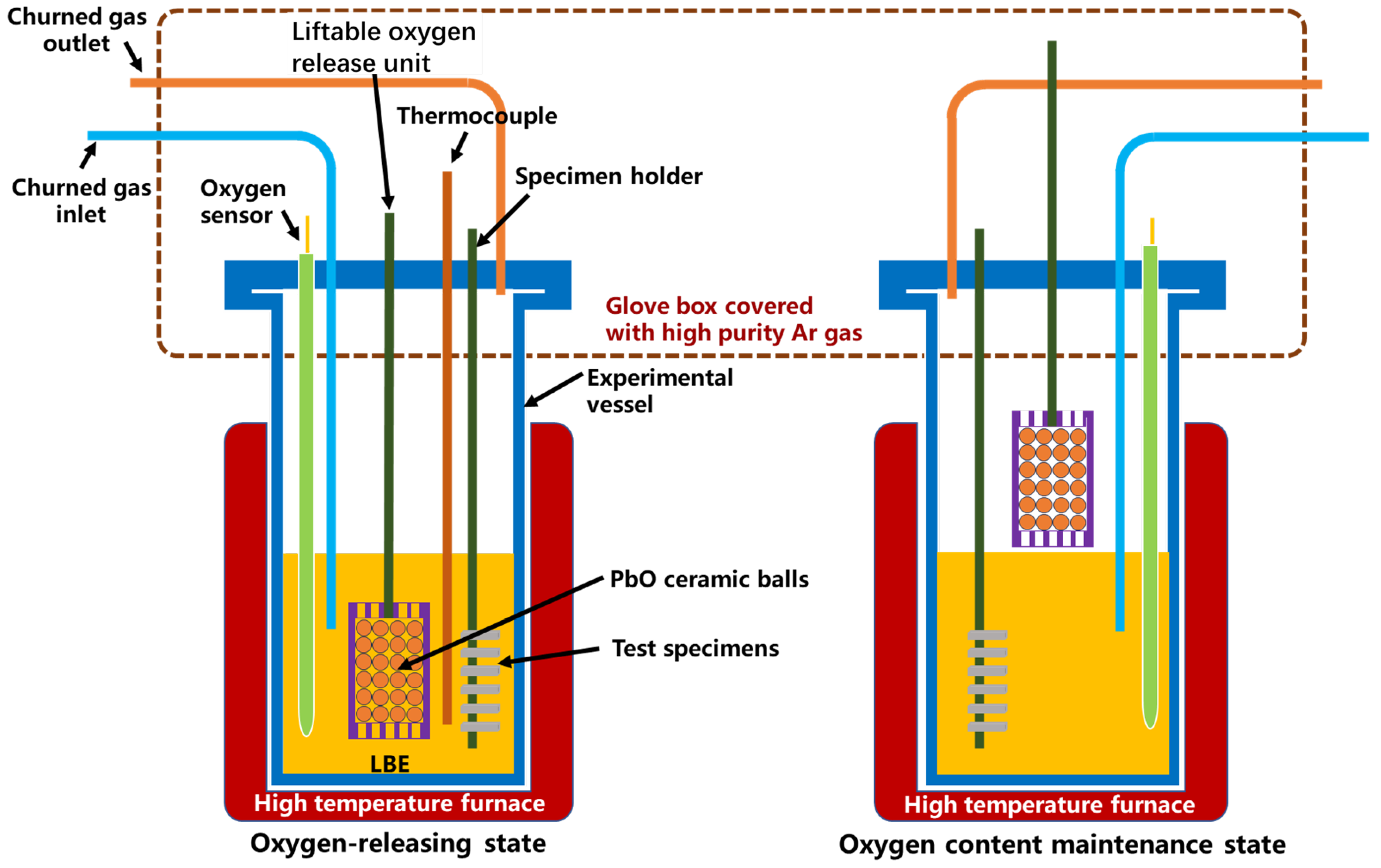
The static LBE corrosion tests were carried out by using a self-designed rotating corrosion device under a high-temperature liquid LBE environment (without rotating). The solid-phase oxygen control method was used to control the oxygen concentration during the corrosion test by using self-made PbO spheres with a self-designed oxygen sensor. The specimen installation and removal operation were performed in a glove box filled with Ar gas to prevent the contamination of air into the corrosion test device. The schematic figure of the corrosion device used in this study is shown in Figure 1. The churned gas (high-purity Ar gas with 5 vol% H2) is used to homogenize the oxygen content in the LBE. Since the expected operation temperature of LFRs is around 550 °C, two temperatures, 550 °C and 610 °C, were selected for the corrosion test. For both temperatures, the oxygen concertation was controlled at a 10−6 wt.% level according to the Ellingham diagram [23], which is enough to form protective oxide layers and without the formation of a PbO deposit. The exposure times of specimens in liquid LBE were 500 h and 2000 h.
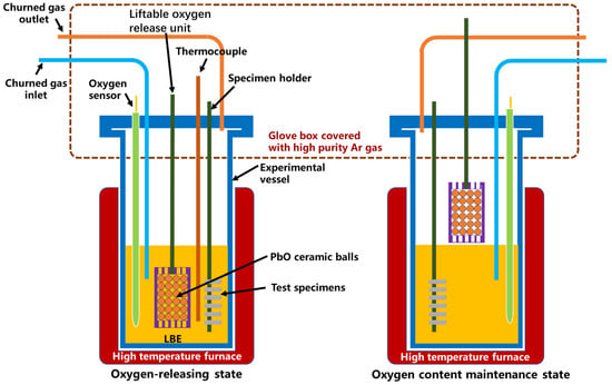
Figure 1.
Schematic figure of the corrosion device.
After the liquid LBE corrosion tests, the cross-section specimen was fabricated from each test specimen. After mounting the cross-section specimen, the cross-sections were ground with SiC paper up to 2000 grit and then fine polished by diamond polishing paste up to 3 µm. In particular, after the 500 h corrosion test, the LBE adhering to the surface of one sample in each condition was removed by using a cleaning solution that consisted of three components, H2O2, CH3COOH, and CH3CH2OH, with a volume ratio of 1:1:1. The specimen surface with LBE removed and other cross-section specimens were then examined using a field emission scanning electron microscope (SEM) equipped with an energy-dispersive spectroscopy (EDS) detector. The SEM model utilized was the Supra55, produced by the Zeiss company in Jena, Germany. The EDS detector was manufactured by the Bruker company in Germany. To have a clearer image of the oxide layer formed on the material surface with LBE possibly remaining, a backscattered-electron (BSE) image was also used for the SEM observation. In this mode, the number of backscattered electrons reaching a BSE detector is proportional to the mean atomic number (Z) of the sample. Thus, brighter areas in the BSE image correlate with a greater average Z in the sample, and dark areas have a lower average Z.
3. Results
3.1. Roughness Measurement of Test Specimens
After specimen preparation, the roughness of the fine and coarse surfaces of each group of test specimens should be checked before the static liquid LBE corrosion test. Table 2 shows the surface roughness measurement result. In this table, four roughness parameters are included: squared mean height (Sq), arithmetic mean height (Sa), average roughness (Ra), and root-mean-square roughness (Rq). Sa is the average vertical distance between the surface contour line and the mean line. Larger Sa values indicate greater surface roughness and vice versa for smoother surfaces. The Sq roughness parameter is the root-mean-square value of the perpendicular distance between the surface contour line and the mean line, indicating the degree of surface roughness dispersion. The larger the Sq value, the greater the degree of dispersion of the surface contour and the more inhomogeneous the surface roughness. Similar to Sa and Sq, Ra and Rq can also represent the specimens’ roughness but in one dimension. Ra is the average distance of the filtered roughness profile determined from deviations about the center line, while Rq is the root-mean-square value of the contour deviation from the mean over the evaluation length.
Table 2.
Roughness measurement results.
In this study, all four roughness parameters of fine polished surfaces for both SRFM-1 and SRFM-2 were larger than those of rough polished surfaces. However, after polishing with 2000 grit SiC paper, the roughness of SRFM-2 is smaller than SRFM-1, indicating a shallower impact depth by grinding for SRFM-2 compared with SRFM-1.
3.2. Stastic Liquid LBE Corrosion Test
3.2.1. XRD
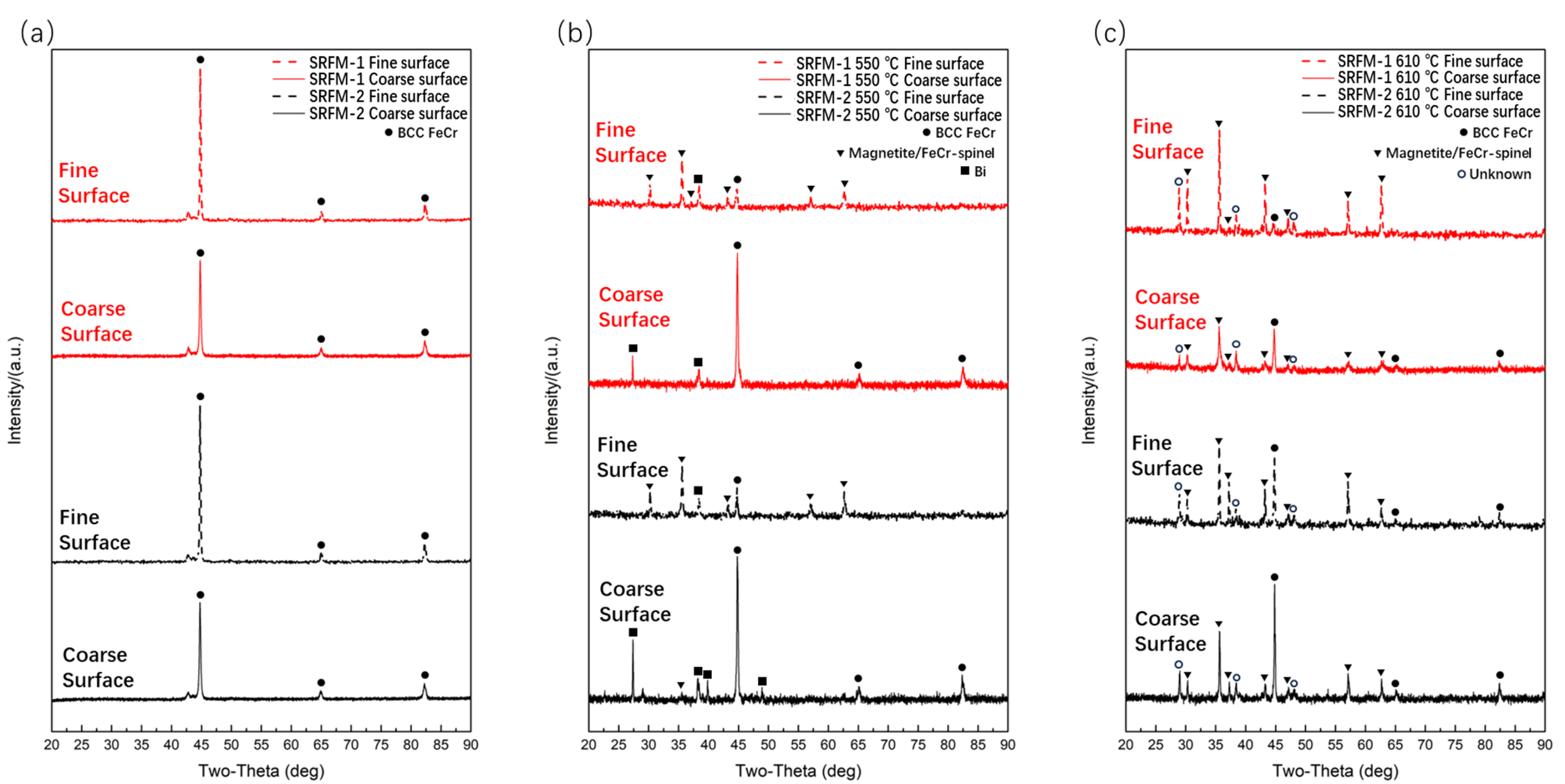
Figure 2 shows the XRD patterns for both SRFM-1 and SRFM-2 specimens before and after the 500 h liquid LBE corrosion test. It should be noted that it is hard to distinguish ferritic and martensite phases of F/M steels using XRD since martensite is a supersaturated solid solution of carbon in α-Fe. Also, it is difficult to distinguish magnetite and FeCr spinel phases for XRD since the Cr atom is a solid solution atom in magnetite.

Figure 2.
The XRD patterns of SRFM-1 and SRFM-2 before and after liquid LBE corrosion for 500 h: (a) before corrosion, (b) after corrosion at 550 °C, and (c) after corrosion at 610 °C.
The original test specimens only contain the BCC FeCr phase. After the 500 h corrosion test at 550 °C, the magnetite or/and FeCr spinel phase showed up on fine polished surfaces for both SRFM-1 and SRFM-2, which indicated the formation of oxide on these surfaces. As for the coarse surfaces of the specimens, no magnetite or FeCr spinel phase was detected, possibly due to two reasons: (1) no oxide layer formed on these surfaces, and (2) the oxide layer is too thin for XRD to detect. The appearance of Bi in Figure 2b mostly shows up on coarse polished surfaces, indicating that there might be adhering LBE remaining on the specimen surface or severe dissolution corrosion occurred, and the Bi is penetrated into the oxide layer or material matrix. Figure 2c shows the surface XRD result after the 500 h corrosion test at 610 °C. Compared with the test result at 550 °C, the magnetite or/and FeCr spinel phase showed up for all test specimen surfaces, even for coarse surfaces, which means whether the surface is fine or coarse, there is oxide formation.
3.2.2. SEM Observation for Specimen Surface after 500 h Corrosion Test
After corrosion at 550 °C for 500 h, the surface SEM observation results are shown in Figure 3. No oxide layer formation occurred for coarse surfaces of SRFM-1 and SRFM-2, and only severe dissolution corrosion occurred, as can be seen in Figure 3b,d. The material near the coarse surface has dissolved into the liquid LBE, confirmed by the surface morphology and EDS point scan results in Figure 3b,d, which means the absence of oxide in the coarse surface XRD result, as shown in Figure 2b, is not due to the insufficient penetration depth of the X-ray. As for the fine surfaces, the formation of the FeCr spinel layer can be confirmed with Si enrichment. The magnetite is separately located on the FeCr spinel layer for SRFM-1 but has a more dense distribution on some parts of the FeCr spinel layer for SRFM-2, as can be seen in Figure 3a,c.
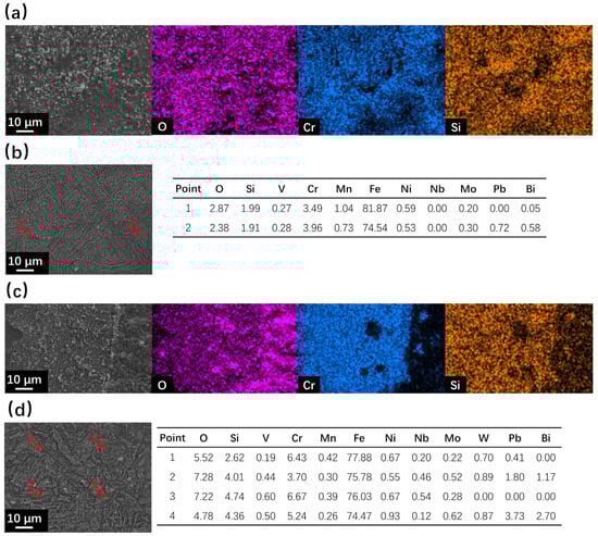
Figure 3.
SEM observation and EDS results of surface areas for SRFM-1 and SRFM-2 after 500 h LBE corrosion test at 550 °C: (a) fine surface of SRFM-1 with an EDS mapping, (b) coarse surface of SRFM-1 with EDS point scan results in wt.%, (c) fine surface of SRFM-2 with an EDS mapping, and (d) coarse surface of SRFM-2 with EDS point scan results in wt.%.
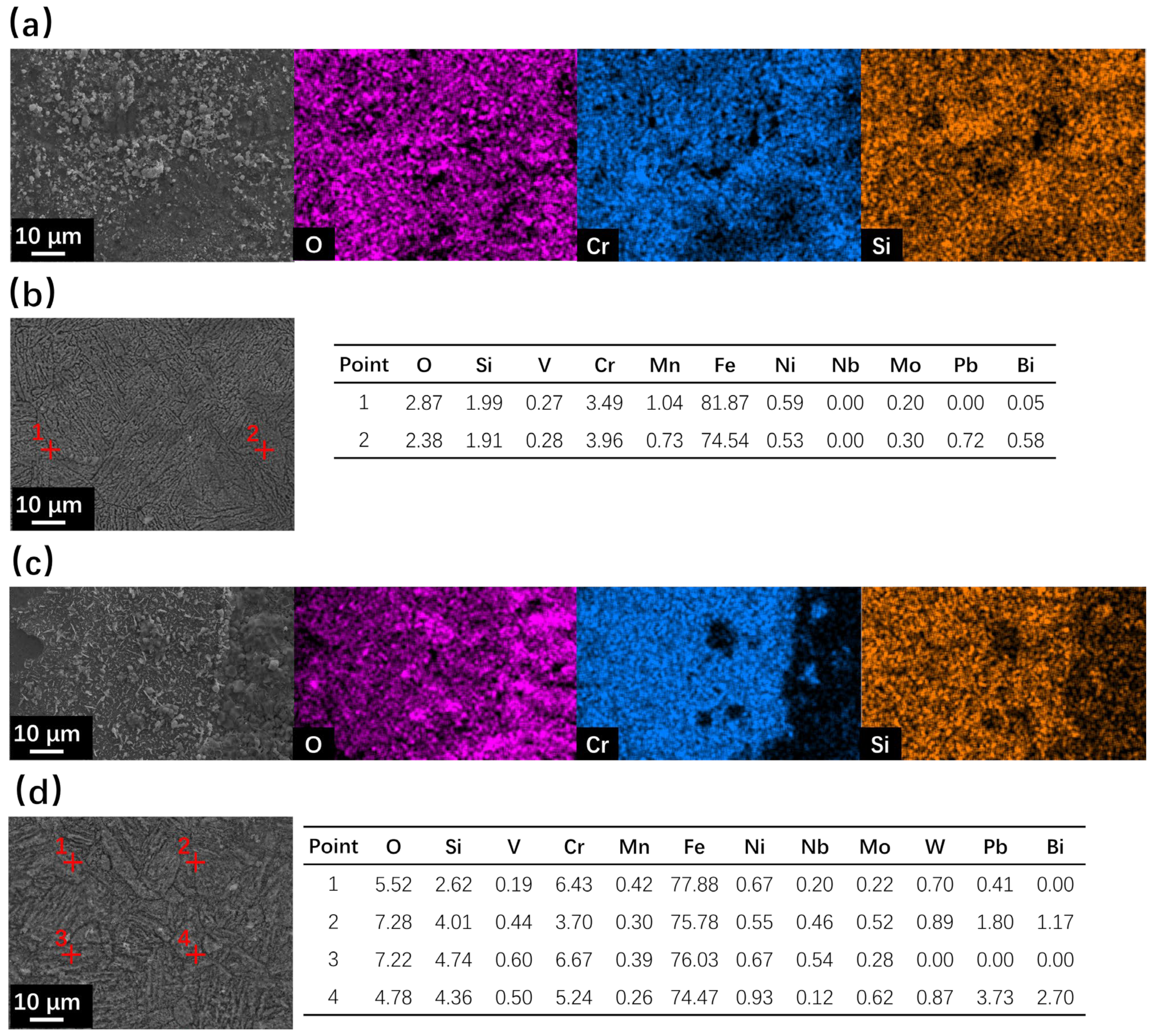
For the specimens after the 500 h corrosion test at 610 °C, the surface SEM with EDS results are shown in Figure 4. The fine surface of SRFM-1 was covered with a magnetite layer with some magnetite particles on it. Moreover, there are many holes on the surface of magnetite, indicating that it is a loose and porous layer. The coarse surface of SRFM-1 is covered with a Si-enriched FeCr spinel layer with magnetite particles of different sizes. However, the dissolution corrosion type morphology around the point 4 area, shown in Figure 4b, indicates the penetration of LBE in the magnetite layer during the corrosion test and was removed by the LBE cleaning process. For SRFM-2, the Si-enriched FeCr spinel layer was detected on both coarse and fine surfaces with discontinuous layers of magnetite adhering to it.
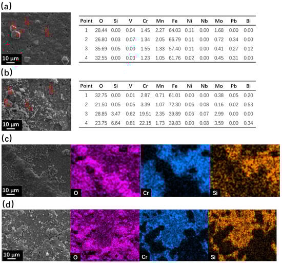
Figure 4.
SEM observation and EDS results of surface areas for SRFM-1 and SRFM-2 after 500 h LBE corrosion test at 610 °C: (a) fine surface of SRFM-1 with EDS point scan results in wt.%, (b) coarse surface of SRFM-1 with EDS point scan results in wt.%, (c) fine surface of SRFM-2 with an EDS mapping, and (d) coarse surface of SRFM-2 with an EDS mapping.
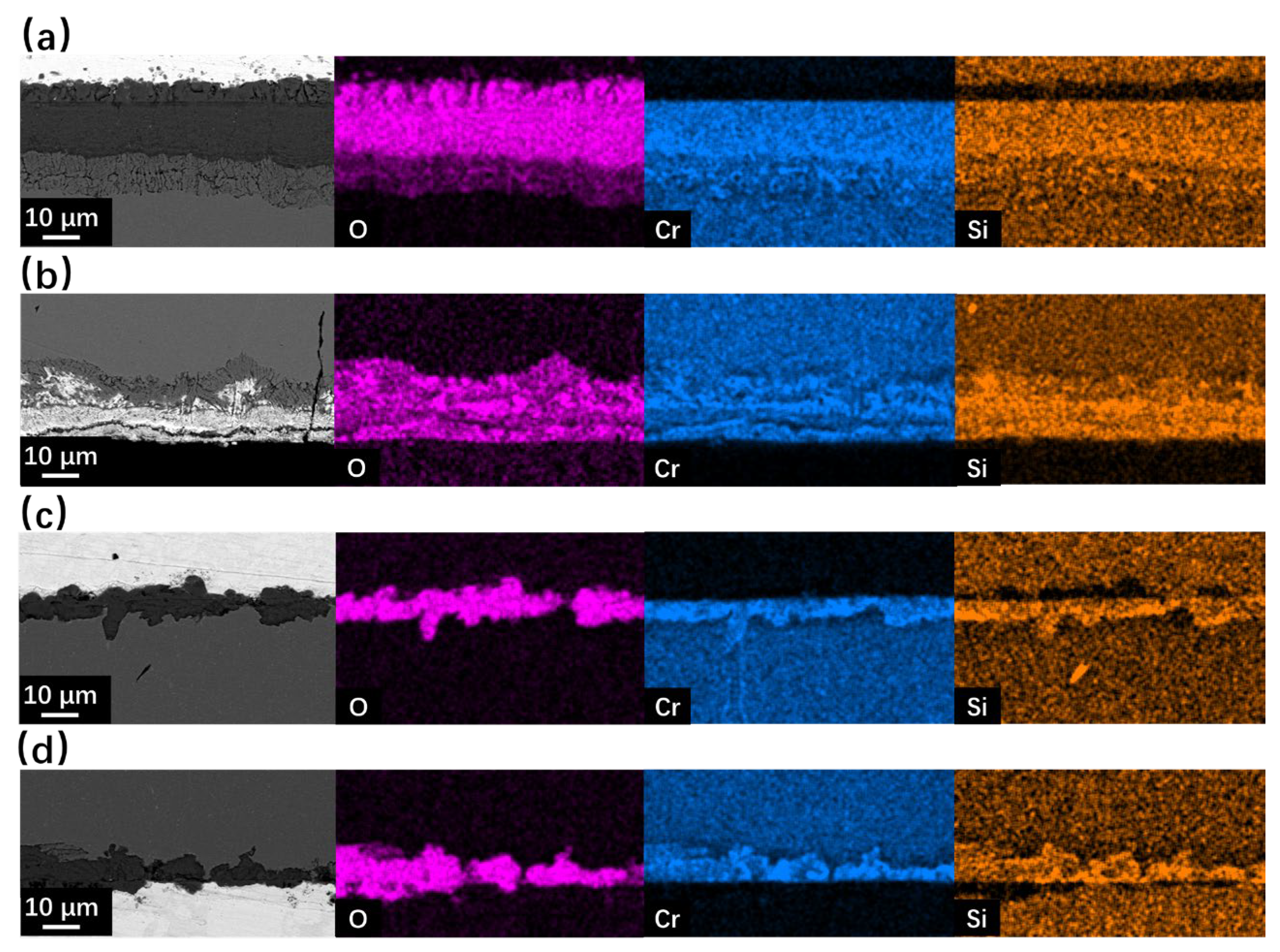
The cross-section SEM observation results of SRFM-1 and SRFM-2 after the 500 h static LBE corrosion test at 550 °C and 610 °C are shown in Figure 5 and Figure 6. In the BSE image, due to the average Z of the material matrix, the oxide layer and the LBE are different. LBE shows the brightest image compared to the material matrix, while the oxide layer has the lowest brightness. At 550 °C, the Si-enriched FeCr spinel oxide layer only exists on fine surfaces of SRFM-1 and SRFM-2. The magnetite layer was not observed in the random-cut cross-sections. Moreover, the penetration of LBE into the FeCr spinel oxide layer was observed on the fine surface of SRFM-2. Compared with the fine surface of SRFM-1 and SRFM-2, no oxide layer formed on the coarse surfaces, and severe dissolution corrosion occurred with LBE dissolved into the material matrix.
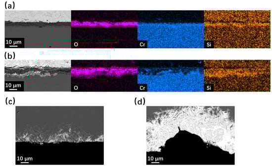
Figure 5.
SEM BSE observation and EDS results of cross-sections for SRFM-1 and SRFM-2 after 500 h LBE corrosion test at 550 °C: (a) fine surface of SRFM-1 with an EDS mapping, (b) fine surface of SRFM-2 with an EDS mapping, (c) coarse surface of SRFM-1, and (d) coarse surface of SRFM-2.

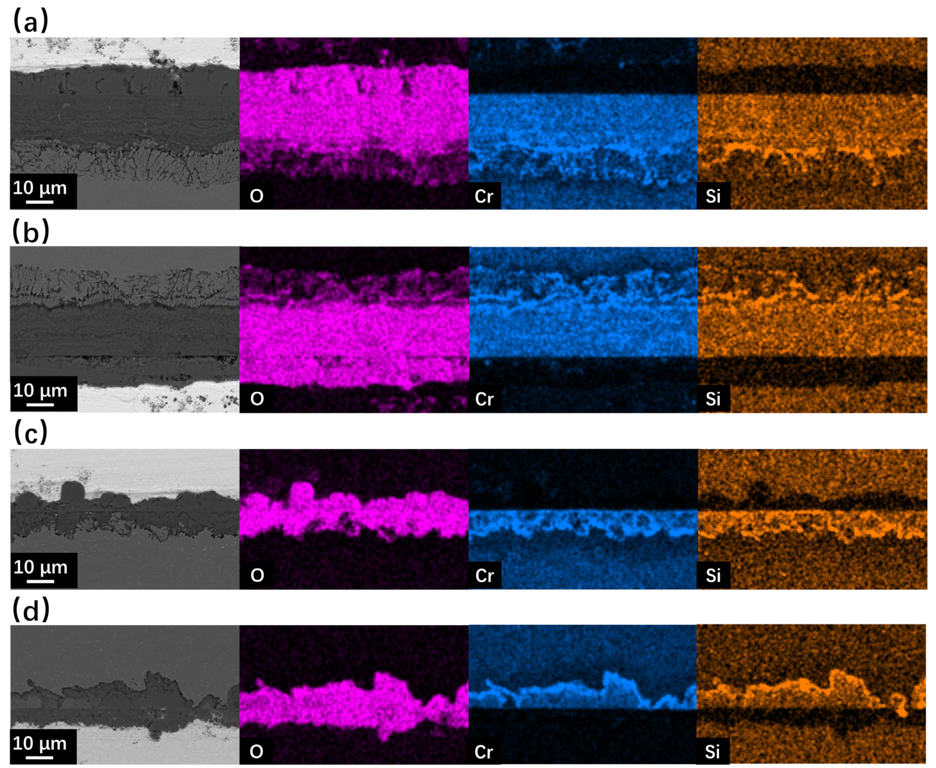
Figure 6.
SEM BSE observation and EDS mapping results of cross-sections for SRFM-1 and SRFM-2 after 500 h LBE corrosion test at 610 °C: (a) fine surface of SRFM-1, (b) coarse surface of SRFM-1, (c) fine surface of SRFM-2, and (d) coarse surface of SRFM-2.
As for the corrosion behavior at 610 °C, the typical oxidation form of F/M steels in LBE was found on the fine surface of SRFM-1, which includes an outer magnetite layer, an inner FeCr-spinel layer, and an internal oxidation zone (IOZ) at the interface of material matrix and oxide. For the coarse surface of SRFM-1, the inner FeCr-spinel layer with an IOZ beneath it was found without the outer magnetite layer. In the FeCr-spinel layer, the concertation of LBE was found, indicating the diffusion of LBE into the inner oxide layer, which stopped at the interface of the FeCr-spinel layer and IOZ. Compared with SRFM-1, the outer magnetite layer and inner FeCr-spinel layer were formed on both fine and coarse surfaces of SRFM-2 without the appearance of IOZ. The oxide layers formed on the SRFM-2 are thinner but more inhomogeneous than SRFM-1. The SEM observation results of the cross-section (Figure 5 and Figure 6) fit well with the results of surface SEM observation results (Figure 3 and Figure 4) and XRD results (Figure 2).
3.2.3. SEM Observation for Specimen Surface after 2000 h Corrosion Test
Figure 7 and Figure 8 show the SEM observation of SRFM-1 and SRFM-2 after the 2000 h corrosion test. As shown in Figure 7 and Figure 8, the uniform oxide layer, which consists of the outer magnetite layer, inner FeCr-spinel layer, and IOZ, was found in most conditions except for the SRFM-2 test at 610 °C, in which almost no IOZ was found. Compared with SRFM-1, the thickness of both the outer and inner oxide layers of SRFM-2 was smaller. However, in some parts of the cross-section specimens, dissolved LBE was detected in the inner FeCr-spinel layer with a much thicker outer magnetite layer and inner FeCr-spinel layer than in LBE-free regions, as shown in Figure 9. This could be due to the initial stage of the oxide layer formation process, such as the morphology observed in Figure 6b. At the beginning stage, LBE dissolved into the oxide layer. With the continuing growth of the oxide layer, the dissolved LBE remained in the inner FeCr-spinel layer and reduced the density of the inner oxide layer, which might also decrease the ability of the oxide layer to prevent the Fe atoms dissolving into the LBE, and finally formed a much thicker outer magnetite layer.

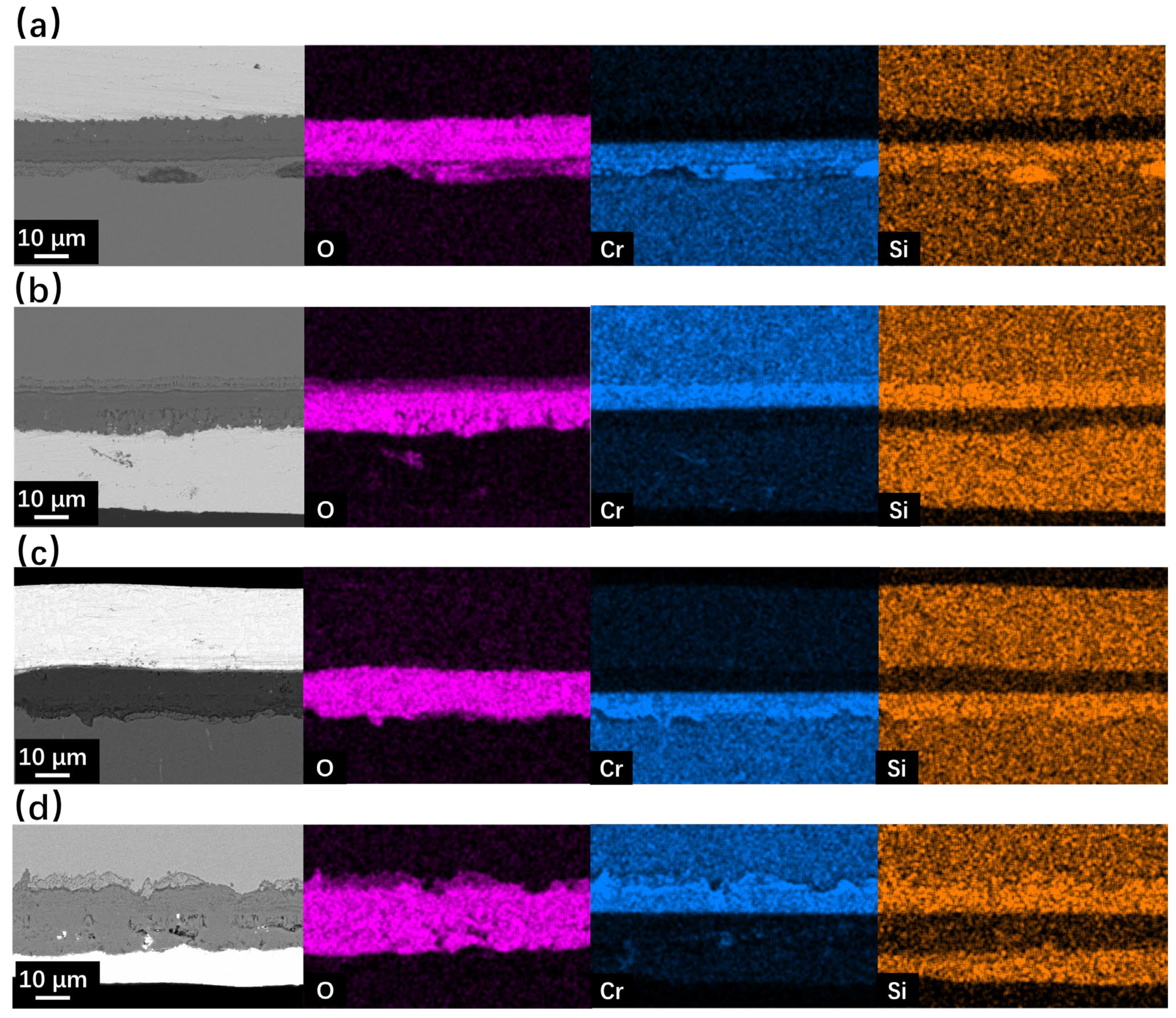
Figure 7.
SEM BSE observation and EDS mapping results of cross-sections for SRFM-1 and SRFM-2 after 2000 h LBE corrosion test at 550 °C: (a) fine surface of SRFM-1, (b) coarse surface of SRFM-1, (c) fine surface of SRFM-2, and (d) coarse surface of SRFM-2.

Figure 8.
SEM BSE observation and EDS mapping results of cross-sections for SRFM-1 and SRFM-2 after 2000 h LBE corrosion test at 610 °C: (a) fine surface of SRFM-1, (b) coarse surface of SRFM-1, (c) fine surface of SRFM-2, (d) coarse surface of SRFM-2.
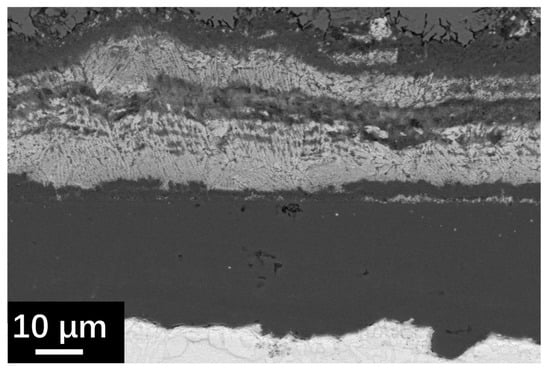
Figure 9.
SEM BSE image of cross-section specimen of SRFM-1 at the coarse surface side after 2000 h LBE corrosion test at 610 °C.
4. Discussion
According to the test result, the surface state significantly influences the corrosion behavior of F/M steels in a liquid LBE environment, especially for the beginning stage.
After a 500 h corrosion test, the coarse surface of SRFM-1 and SRFM-2 tested at 550 °C under solid-phase oxygen control shows pure-dissolve corrosion behavior without forming oxide layers, as shown in Figure 5c,d. In the 610 °C condition, the coarse surface of SRFM-1 shows much more severe dissolution corrosion than the fine surface. Only for SRFM-2 tested at 610 °C condition does the surface state have no obvious effect on the corrosion behavior. After a 2000 h corrosion test, the surface state shows almost no significant influence on the corrosion behavior. Only the material part experienced dissolution corrosion due to the surface-state influence at the beginning stage of corrosion, showing much thicker oxide layers with dissolved LBE in the oxide layer. The structure and composition of the oxide layer formed on the Si-reinforced F/M steels after both the 500 h and 2000 h corrosion tests match the experimental results of others [24,28,31,32,34,35,36,37,38,39]. However, the study on the effect of the surface state on LBE corrosion is limited. The strong influence of the surface state on the LBE corrosion behavior reported in this study fulfills the lack in this study area.
This corrosion-behavior change induced by the surface state is possibly due to a competitive corrosion mechanism. In this study, the distance between the coarse surface and the fine surface is about 2 mm, much smaller than the total size of the specimen. Therefore, during the initial corrosion stage, one surface is more favorable to forming the oxide layer, which is the fine surface in this study. Then, the area close to the coarse surface might experience a lower O concentration and be more likely to show a dissolution corrosion behavior. With the continuing corrosion test, the competitive corrosion mechanism finally reached a balanced point since the oxide-layer formation speed decreased with increased corrosion time. Then, the oxide layer started to grow near the coarse surface region with enough O concentration. Further detailed experiments or simulation works are needed to identify the correctness of this theory.
5. Conclusions
This study investigated the corrosion behavior of two types of Si-reinforced F/M steels with different surface states by static liquid LBE corrosion test under solid-phase oxygen-controlled conditions for 500 h and 2000 h at 550 °C and 610 °C. The following conclusions were obtained:
Firstly, at the initial corrosion stage, except for Si-reinforced 11Cr F/M steel tested at 610 °C, the coarse polished surface (the Sa values for SRFM-1 and SRFM-2 were 0.067 and 0.044 μm, respectively) shows severe dissolution corrosion behavior compared with the fine polished surface (the Sa values for SRFM-1 and SRFM-2 were 0.014 and 0.023 μm, respectively), which shows oxidation behavior.
Secondly, at 610 °C, the surface state has almost no influence on the corrosion behavior for Si-enriched 11Cr F/M steel for both the 500 h and 2000 h experiments.
Thirdly, at 550 °C, Si-reinforced 9Cr and 11Cr F/M steels show similar corrosion behavior. However, at 610 °C, Si-reinforced 11Cr F/M steel shows better liquid LBE corrosion resistance due to its thinner oxide layer formation.
Author Contributions
Conceptualization, Y.L.; methodology, Y.L. and B.Q.; validation, B.Q., X.F. and B.L.; formal analysis, B.Q., X.F. and B.L.; investigation, Y.L.; resources, B.Q., X.F. and B.L.; data curation, Y.L.; writing—original draft preparation, Y.L.; writing—review and editing, B.Q. and X.F.; visualization, Y.L.; supervision, B.L.; project administration, B.L. and B.Q.; funding acquisition, Y.L.; All authors have read and agreed to the published version of the manuscript.
Funding
This research was funded by the Director of the Reactor Engineering Technology Research Institute of China Institute of Atomic Energy, grant number 218205.
Data Availability Statement
The original contributions presented in the study are included in the article, further inquiries can be directed to the corresponding author.
Conflicts of Interest
The authors declare no conflicts of interest.
Correction Statement
This article has been republished with a minor correction to resolve spelling errors. This change does not affect the scientific content of the article.
References
- Was, G.S. Challenges to the use of ion irradiation for emulating reactor irradiation. J. Mater. Res. 2015, 30, 1158–1182. [Google Scholar] [CrossRef]
- Fazio, C.; Sobolev, V.P.; Aerts, A.; Gavrilov, S.; Lambrinou, K.; Schuurmans, P.; Hwang, I.S. Handbook on Lead-Bismuth Eutectic Alloy and Lead Properties, Materials Compatibility, Thermal-Hydraulics and Technologies-2015 Edition (No. NEA--7268); Organisation for Economic Co-Operation and Development: Paris, France, 2015. [Google Scholar]
- Gong, X.; Short, M.P.; Auger, T.; Charalampopoulou, E.; Lambrinou, K. Environmental degradation of structural materials in liquid lead-and lead-bismuth eutectic-cooled reactors. Prog. Mater. Sci. 2022, 126, 100920. [Google Scholar] [CrossRef]
- Weisenburger, A.; Heinzel, A.; Müller, G.; Muscher, H.; Rousanov, A. T91 cladding tubes with and without modified FeCrAlY coatings exposed in LBE at different flow, stress and temperature conditions. J. Nucl. Mater. 2008, 376, 274–281. [Google Scholar] [CrossRef]
- Dou, P.; Kasada, R. Preliminary study on nano-and micro-composite sol–gel based alumina coatings on structural components of lead–bismuth eutectic cooled fast breeder reactors. J. Nucl. Mater. 2011, 409, 177–182. [Google Scholar] [CrossRef]
- Rivai, A.K.; Takahashi, M. Compatibility of surface-coated steels, refractory metals and ceramics to high temperature lead–bismuth eutectic. Prog. Nucl. Energy 2008, 50, 560–566. [Google Scholar] [CrossRef]
- Zhong, Y.; Zhang, W.; Chen, Q.; Yang, J.; Zhu, C.; Li, Q.; Yang, J.; Liu, N.; Yang, J. Effect of LBE corrosion on microstructure of amorphous Al2O3 coating by magnetron sputtering. Surf. Coat. Technol. 2022, 443, 128598. [Google Scholar] [CrossRef]
- Deng, J.; Yang, J.; Lv, L.; Zhang, W.; Chen, Q.; Zhou, M.; Zhu, C.; Liu, N.; Yang, J. Corrosion behavior of refractory TiNbZrMoV high-entropy alloy coating in static lead-bismuth eutectic alloy: A novel design strategy of LBE corrosion-resistant coating? Surf. Coat. Technol. 2022, 448, 128884. [Google Scholar] [CrossRef]
- Serag, E.; Caers, B.; Schuurmans, P.; Lucas, S.; Haye, E. Challenges and coating solutions for wear and corrosion inside Lead Bismuth Eutectic: A review. Surf. Coat. Technol. 2022, 441, 128542. [Google Scholar] [CrossRef]
- Yang, J.; Zhao, K.; Wang, G.; Deng, C.; Liu, N.; Zhang, W.; Yang, J. Influence of coating thickness on microstructure, mechanical and LBE corrosion performance of amorphous AlCrFeTiNb high-entropy alloy coatings. Surf. Coat. Technol. 2022, 441, 128502. [Google Scholar] [CrossRef]
- Yin, X.; Wang, Y.; Wang, H.; Zhao, K.; Sun, Y.; Xiao, J.; Zhao, Y.; Gong, F.; Chen, Y. Corrosion behavior and failure mechanism of amorphous Al2O3 coating at high-temperature LBE. Vacuum 2023, 215, 112251. [Google Scholar] [CrossRef]
- Zhang, W.; Deng, J.; Yue, H.; Hu, S.; Qiu, X.; Yin, H.; Li, Q.; Liu, H.; Zhou, M.; Yang, J. Corrosion behavior of the FeCrAl coating with different Cr and Al contents before and after Au-ions irradiation in stagnant LBE. Corros. Sci. 2023, 225, 111590. [Google Scholar] [CrossRef]
- Zhang, P.; Yao, Z.; Lin, S.; Liu, Y.; Lu, S.; Wu, X. Enhancing LBE corrosion resistance through inhibition diffusion approach for AlTixCrFe HEA coating. Appl. Surf. Sci. 2024, 699, 160535. [Google Scholar] [CrossRef]
- Zhang, W.; Zhong, Y.; Qiu, X.; Li, Q.; Yue, H.; Zhou, Y.; Deng, J.; Yang, J.; Liu, H.; Li, Q.; et al. Screening of the FeCrAl LBE corrosion-resistant coatings: The effect of Cr and Al contents. Surf. Coat. Technol. 2023, 462, 129477. [Google Scholar] [CrossRef]
- Vogt, J.B.; Proriol Serre, I. A review of the surface modifications for corrosion mitigation of steels in lead and LBE. Coatings 2021, 11, 53. [Google Scholar] [CrossRef]
- Wan, Q.; Wu, Z.Y.; Liu, Y.; Yang, B.; Liu, H.D.; Ren, F.; Wang, P.; Xiao, Y.Y.; Zhang, J.; Zhang, G.D. Lead-bismuth eutectic (LBE) corrosion mechanism of nano-amorphous composite TiSiN coatings synthesized by cathodic arc ion plating. Corros. Sci. 2021, 183, 109264. [Google Scholar] [CrossRef]
- Yang, J.; Shi, K.; Zhang, W.; Chen, Q.; Ning, Z.; Zhu, C.; Liao, J.; Yang, Y.; Liu, N.; Yang, J. A novel AlCrFeMoTi high-entropy alloy coating with a high corrosion-resistance in lead-bismuth eutectic alloy. Corros. Sci. 2021, 187, 109524. [Google Scholar] [CrossRef]
- Schroer, C.; Konys, J.; Furukawa, T.; Aoto, K. Oxidation behaviour of P122 and a 9Cr–2W ODS steel at 550 C in oxygen-containing flowing lead–bismuth eutectic. J. Nucl. Mater. 2010, 398, 109–115. [Google Scholar] [CrossRef]
- Ganesan, R.; Gnanasekaran, T.; Srinivasa, R.S. Diffusivity, activity and solubility of oxygen in liquid lead and lead–bismuth eutectic alloy by electrochemical methods. J. Nucl. Mater. 2006, 349, 133–149. [Google Scholar] [CrossRef]
- Courouau, J.L.; Robin, J.C. Chemistry control analysis of lead alloys systems to be used as nuclear coolant or spallation target. J. Nucl. Mater. 2004, 335, 264–269. [Google Scholar] [CrossRef]
- Li, N. Active control of oxygen in molten lead–bismuth eutectic systems to prevent steel corrosion and coolant contamination. J. Nucl. Mater. 2002, 300, 73–81. [Google Scholar] [CrossRef]
- Schroer, C.; Wedemeyer, O.; Novotny, J.; Skrypnik, A.; Konys, J. Long-term service of austenitic steel 1.4571 as a container material for flowing lead–bismuth eutectic. J. Nucl. Mater. 2011, 418, 8–15. [Google Scholar] [CrossRef]
- Qin, B.; Fu, X.G.; Ma, H.R. Preliminary experiment study on control of oxygen concentration via gas phase in liquid lead-bismuth alloy. Mater. Rep. 2019, 33, 1821–1824. [Google Scholar]
- Schroer, C.; Koch, V.; Wedemeyer, O.; Skrypnik, A.; Konys, J. Silicon-containing ferritic/martensitic steel after exposure to oxygen-containing flowing lead–bismuth eutectic at 450 and 550 C. J. Nucl. Mater. 2016, 469, 162–176. [Google Scholar] [CrossRef]
- Chen, L.; Xu, S.; Schroer, C.; Jia, H.; Ruan, Z.; Qin, B.; Zhou, Z.; Long, B. Comparison of Corrosion Behavior of T91, 9Cr and 9CrAl ODS Steels in Liquid Pb. Materials 2023, 16, 2295. [Google Scholar] [CrossRef] [PubMed]
- Li, N.; Parker, S.S.; Saleh, T.A.; Maloy, S.A.; Nelson, A.T. Intermediate temperature corrosion behaviour of Fe-12Cr-6Al-2Mo-0.2 Si-0.03 Y alloy (C26M) at 300–600 °C. Corros. Sci. 2019, 157, 274–283. [Google Scholar] [CrossRef]
- Popovic, M.P.; Chen, K.; Shen, H.; Stan, C.V.; Olmsted, D.L.; Tamura, N.; Asta, M.; Abad, M.D.; Hosemann, P. A study of deformation and strain induced in bulk by the oxide layers formation on a Fe-Cr-Al alloy in high-temperature liquid Pb-Bi eutectic. Acta Mater. 2018, 151, 301–309. [Google Scholar] [CrossRef]
- Kurata, Y. Corrosion behavior of Si-enriched steels for nuclear applications in liquid lead–bismuth. J. Nucl. Mater. 2013, 437, 401–408. [Google Scholar] [CrossRef]
- Short, M.P.; Ballinger, R.G.; Hänninen, H.E. Corrosion resistance of alloys F91 and Fe–12Cr–2Si in lead–bismuth eutectic up to 715 C. J. Nucl. Mater. 2013, 434, 259–281. [Google Scholar] [CrossRef]
- Chen, L.; Tsisar, V.; Wang, M.; Schroer, C.; Zhou, Z. Effect of oxygen on corrosion of an alumina-forming duplex steel in static liquid lead-bismuth eutectic at 550 °C. Corros. Sci. 2021, 189, 109591. [Google Scholar] [CrossRef]
- Wang, J.; Lu, S.; Rong, L.; Li, D.; Li, Y. Effect of silicon on the oxidation resistance of 9 wt.% Cr heat resistance steels in 550 C lead-bismuth eutectic. Corros. Sci. 2016, 111, 13–25. [Google Scholar] [CrossRef]
- Shi, H.; Wang, H.; Fetzer, R.; Heinzel, A.; Weisenburger, A.; Wang, K.; Jianu, A.; Müller, G. Influence of Si addition on the corrosion behavior of 9 wt% Cr ferritic/martensitic steels exposed to oxygen-controlled molten Pb-Bi eutectic at 550 and 600 °C. Corros. Sci. 2021, 193, 109871. [Google Scholar] [CrossRef]
- Ejenstam, J.; Szakálos, P. Long term corrosion resistance of alumina forming austenitic stainless steels in liquid lead. J. Nucl. Mater. 2015, 461, 164–170. [Google Scholar] [CrossRef]
- Chen, G.; Zhang, Z.; Feng, S.; Jiang, K.; Yu, J.; Wu, H.; Shi, S.; Lin, Q. Improvement of low-cycle fatigue behavior of modified 9Cr-1Mo steels at 450 °C in liquid LBE environment by the addition of Si element. Nucl. Eng. Des. 2023, 413, 112570. [Google Scholar] [CrossRef]
- Chen, Q.; Zhai, L.; Chen, Y.; Liu, H.; Yang, J.; Zhang, F. Corrosion behaviour of 11Cr1Si ferritic/martensitic steel in static liquid lead–bismuth eutectic at 450–550 °C. Nucl. Mater. Energy 2023, 35, 101429. [Google Scholar] [CrossRef]
- Zhang, W.H.; Wang, Z.B.; Lu, K. Enhanced oxidation resistance of a reduced activation ferritic/martensitic steel in liquid Pb-Bi eutectic alloy by preforming a gradient nanostructured surface layer. J. Nucl. Mater. 2018, 507, 151–157. [Google Scholar] [CrossRef]
- Dong, H.; Wang, P.; Li, D.; Li, Y. Effect of pre-deformation on the oxidation resistance of a high Si ferritic/martensitic steel in oxygen-saturated stagnant lead-bismuth eutectic at 550 C. Corros. Sci. 2017, 118, 129–142. [Google Scholar] [CrossRef]
- Wu, X.; Rong, L.; Tan, J.; Chen, S.; Hu, X.; Zhang, Y.; Zhang, Z. Research Advance on Liquid Lead-Bismuth Eutectic Corrosion Resistant Si Enhanced Ferritic/Martensitic and Austenitic Stainless Steels. Acta Met. Sin. 2023, 59, 502–512. [Google Scholar]
- Liu, H.; Chen, Q.; Li, Q.; Li, Y.; Yang, J. Influence of Si addition on the corrosion behavior of 9Cr ferritic/martensitic steel in static liquid lead-bismuth eutectic. Mater. Res. Express 2024. [Google Scholar] [CrossRef]
- Chen, S.; Rong, L. Effect of silicon on the microstructure and mechanical properties of reduced activation ferritic/martensitic steel. J. Nucl. Mater. 2015, 459, 13–19. [Google Scholar] [CrossRef]
- Van den Bosch, J.; Coen, G.; Hosemann, P.; Maloy, S.A. On the LME susceptibility of Si enriched steels. J. Nucl. Mater. 2012, 429, 105–112. [Google Scholar] [CrossRef]
- Gong, X.; Sun, L.; Zhang, F.; Yin, Y.; Huang, X.; Gong, H.; Liu, Y. Effect of alloying elements on liquid metal embrittlement of pure BCC Fe in contact with liquid lead-bismuth eutectic: Experiments and first principles calculation. Corros. Sci. 2022, 208, 110522. [Google Scholar] [CrossRef]
- Ilinčev, G.; Kárník, D.; Paulovič, M.; Doubková, A. The impact of the composition of structural steels on their corrosion stability in liquid Pb–Bi at 500 and 400 °C with different oxygen concentrations. J. Nucl. Mater. 2004, 335, 210–216. [Google Scholar] [CrossRef]
- Martín-Muñoz, F.J.; Soler-Crespo, L.; Gómez-Briceño, D. Assessment of the influence of surface finishing and weld joints on the corrosion/oxidation behaviour of stainless steels in lead bismuth eutectic. J. Nucl. Mater. 2011, 416, 80–86. [Google Scholar] [CrossRef]
- Wang, D.; Liu, S.; Ma, X.; Gong, X.; Zhu, H.; Niu, F. Enhanced corrosion resistance of 15–15Ti austenitic steel in liquid lead-bismuth eutectic at 550 °C by shot peening processing. Corros. Sci. 2024, 226, 111640. [Google Scholar] [CrossRef]


Disclaimer/Publisher’s Note: The statements, opinions and data contained in all publications are solely those of the individual author(s) and contributor(s) and not of MDPI and/or the editor(s). MDPI and/or the editor(s) disclaim responsibility for any injury to people or property resulting from any ideas, methods, instructions or products referred to in the content. |
© 2024 by the authors. Licensee MDPI, Basel, Switzerland. This article is an open access article distributed under the terms and conditions of the Creative Commons Attribution (CC BY) license (https://creativecommons.org/licenses/by/4.0/).