Article

Tensile Properties and Fracture Analysis of Duplex (2205) and Super Duplex (2507) Stainless Steels, Produced via Laser Powder Bed Fusion Additive Manufacturing

by
Leonidas Karavias
1,
Leonidas Gargalis
1,
Joachim Seland Graff
2,
Marius Johansen
2,
Spyros Diplas
2,* and
Evaggelia K. Karaxi
1
1
Conify, P. Nikolaidi 23A, 182 33 Agios Ioannis Rentis, Greece
2
SINTEF Industry, Forskningsveien 1, 0373 Oslo, Norway
*
Author to whom correspondence should be addressed.
Metals 2024, 14(7), 838; https://doi.org/10.3390/met14070838
Submission received: 12 June 2024 / Revised: 16 July 2024 / Accepted: 17 July 2024 / Published: 22 July 2024

Abstract

:
Additive manufacturing of duplex (DSS) and super duplex stainless steel (SDSS) has been successfully demonstrated using laser powder bed fusion (LPBF) in recent years. Owing to the high cooling rates, as-built LPBF-processed DSS and SDSS exhibit close to 100% ferritic microstructures and require heat treatment at 1000–1300 °C to obtain the desired duplex microstructure. In this work, the mechanical properties of DSS and SDSS processed via LPBF were investigated in three building directions (vertical, horizontal, diagonal) and three processing conditions (as-built, stress-relieved, annealed, and quenched) using uniaxial tensile testing. As-built samples exhibited tensile and yield strength greater than 1000 MPa accompanied by less than 20% elongation at break. In comparison, the water-quenched samples and samples annealed at 1100 °C exhibited elongation at break greater than 34% with yield and tensile strength values less than 950 MPa. Stress relief annealing at 300 °C had a negligible impact on the mechanical properties. Austenite formation upon high-temperature annealing restored the reduced ductility of the as-built samples. The as-built and stress-relieved SDSS showed the highest yield and tensile strength values in the horizontal build direction, reaching up to ≈1400 and ≈1500 MPa (for SDSS), respectively, as compared to the vertical and diagonal directions. Fractographic investigation after tensile testing revealed predominantly a quasi-ductile failure mechanism, showing fine size dimple formation and cleavage facets in the as-built state and a fully ductile fracture in the annealed and quenched conditions. The findings in this study demonstrate the mechanical anisotropy of DSS and SDSS along three different build orientations, 0°, 45°, 90°, and three post-processing conditions.

1. Introduction

Traditionally, duplex stainless steel (DSS) and super duplex stainless steel (SDSS) are produced via casting, forging, machining, rolling, or a combination of these methods [1,2,3,4]. Laser powder bed fusion (LPBF) additive manufacturing is advantageous compared to traditional manufacturing, since it circumvents extended processing cycles, elevated costs, and intricate machining. It also offers substantial benefits in the fabrication of intricate components, due to its enhanced flexibility and precision [5,6]. Components produced via LPBF exhibit distinctive microstructures typical of the high-temperature gradients and rapid solidification conditions within the melt pool. This leads to the development of an epitaxial-to-columnar grain structure aligned along the build direction. The microstructural morphology, crystallography, and average grain size undergo notable variations in response to alterations in process parameters and laser scanning configurations [7]. The capability of LPBF to generate fine grains and substructures contributes to enhanced mechanical properties when compared to conventionally manufactured wrought, cast, and forged parts [7,8,9,10,11].
Under near-equilibrium conditions characterized by low cooling rates, DSSs and SDSSs undergo solidification through a ferritic–austenitic transformation, where the initial ferrite solidification is followed by austenite formation [12,13]. However, under non-equilibrium conditions, such as those associated with the high cooling rates (up to 105–106 °C/s) in LPBF [14], the developed microstructure is predominantly ferritic due to a shift from ferrite–austenite (FA) to solely ferrite (F) solidification [15]. Consequently, numerous LPBF-related studies have consistently reported a mainly ferritic microstructure in DSS and SDSS [16,17,18,19,20]. Given the prevalence of ferrite in the as-built LPBF microstructure, nitrogen (N) supersaturation within the ferrite matrix has been identified as a factor inducing chromium nitride precipitation [9,20]. The most common precipitates in duplex stainless steels, including the secondary phases sigma (σ) and chi (χ), chromium nitrides, and carbides, form within 600–1000 °C [21]. However, the extremely high cooling rates upon LPBF processing impede the formation of the σ and χ phases. Instead, secondary nanophases (α′, G) typically precipitate within the range of 300–550 °C upon prolonged heat exposure [22,23].
The predominantly ferritic microstructure, and the presence of chromium nitride precipitates in combination with the high dislocation density in as-built LPBF-processed DSS and SDSS, result in high yield strength (YS) and ultimate tensile strength (UTS) values but a subsequent decrease in elongation to break (EL) and reduced fracture toughness [9,20]. Previous fractographic analysis of as-built DSS and SDSS has revealed a mixed fracture mode consisting of both ductile and brittle features [24]. Post-processing solution annealing at elevated temperatures (above 1000 °C) followed by quenching demonstrated an augmentation in the austenite content leading to a balanced austenite–ferrite phase distribution [16]. This post-processing heat treatment effectively inhibits the formation of secondary phases and dissolves the chromium nitrides created during the LPBF process, both of which can deteriorate mechanical properties (such as fracture toughness) and corrosion resistance. After solution annealing and quenching, the development of a recrystallized duplex microstructure featuring increased austenite content facilitates the recovery of EL while concurrently resulting in a decrease in hardness, YS, and UTS [17,20,24,25]. Moreover, analysis of the tensile fractured surface reveals a distinctly ductile morphology [18,24].
Most of previous studies on LPBF DSS and SDSS have focused on their tensile properties along the vertical build orientation in the as-built as well as annealed and quenched conditions. Jeffs et al. [26] and Zhang et al. [27] studied the tensile behavior along the vertical and horizontal build orientations of DSS only in the annealed and quenched state. A mechanical anisotropy was reported [27] for DSS in its annealed and quenched state with the horizontal orientation exhibiting higher YS and UTS. This was ascribed to the combined influence of grain size and shape, grain orientation, and the presence of geometrically necessary dislocations on strength, in conjunction with the work hardening rate. Several studies have investigated the anisotropy in mechanical properties of various LPBF-produced alloys, such as Ti-alloys [28], Al-alloys [29], and stainless steel [30]. The differences in the mechanical properties between the build orientations were attributed to processing-related factors such as heat dissipation during rapid solidification [31], grain size and shape variability [31,32], as well as crystallographic texture [33].
The primary focus of this work was to investigate the tensile properties of DSS and SDSS produced via LPBF, considering different build orientations and heat treatments. The impact of various build orientations (0°—horizontal, 45°—diagonal, and 90°—vertical) on the tensile properties of these alloys was assessed, which has not been thoroughly investigated in the existing literature. In addition, the influence of stress relieving, solution annealing, and water quenching on YS, UTS, and %EL was investigated and correlated with the respective microstructures. Furthermore, a comparative analysis was conducted, contrasting the mechanical properties of the LPBF-produced DSS and SDSS in this study with literature cases of DSS and SDSS manufactured via conventional methods as well as via LPBF. Lastly, a fractographic analysis was performed to reveal the fracture mechanism and the origin of the final fracture surface.

2. Materials and Methods

2.1. DSS and SDSS Powders

Commercially available gas-atomized duplex stainless steel (DSS) grade 2205 (MARS F51, Mimete S.r.l., Biassono, Italy) and super duplex stainless steel (SDSS) 2507 (MARS F53, Mimete S.r.l., Biassono, Italy) metal powders were used as LPBF feedstock. The chemical compositions are shown in Table 1. The average size of the powder particles was 21.5 μm and 25.4 μm, with 90% of the particles (D90) below 62.5 μm and 59.1 μm for DSS and SDSS alloys, respectively. The morphology depicted in Figure 1 illustrates that the predominant form of both powders is spherical, with minor occurrences of satellite particles, agglomerations, and elongated particles. Images were taken utilizing a Phenom ProX (Thermo Fisher Scientific Inc., Waltham, MA, USA) scanning electron microscope (SEM) using an acceleration voltage of 15 kV.

2.2. Manufacturing of Tensile Bars and Heat Treatment Procedures

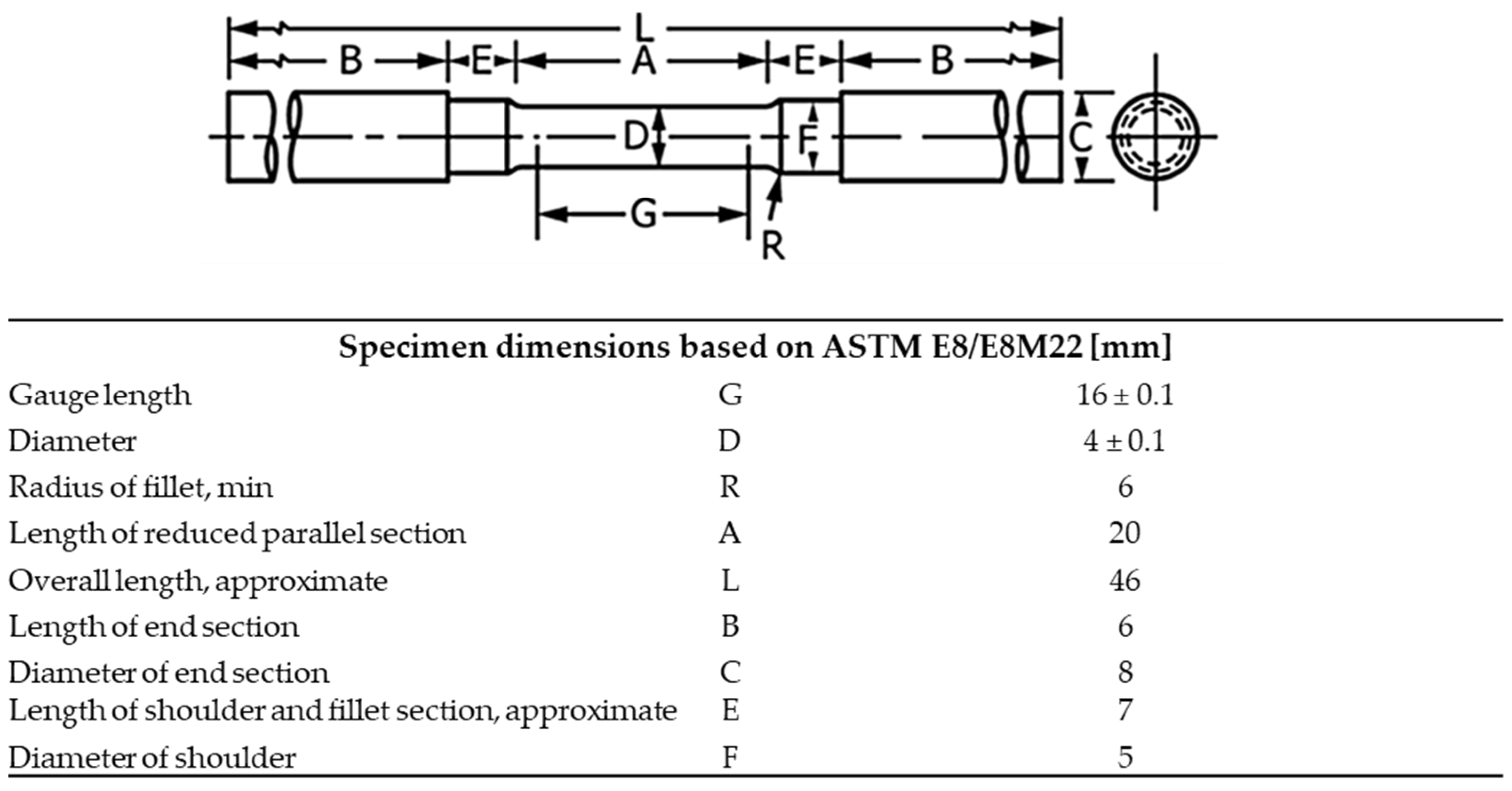
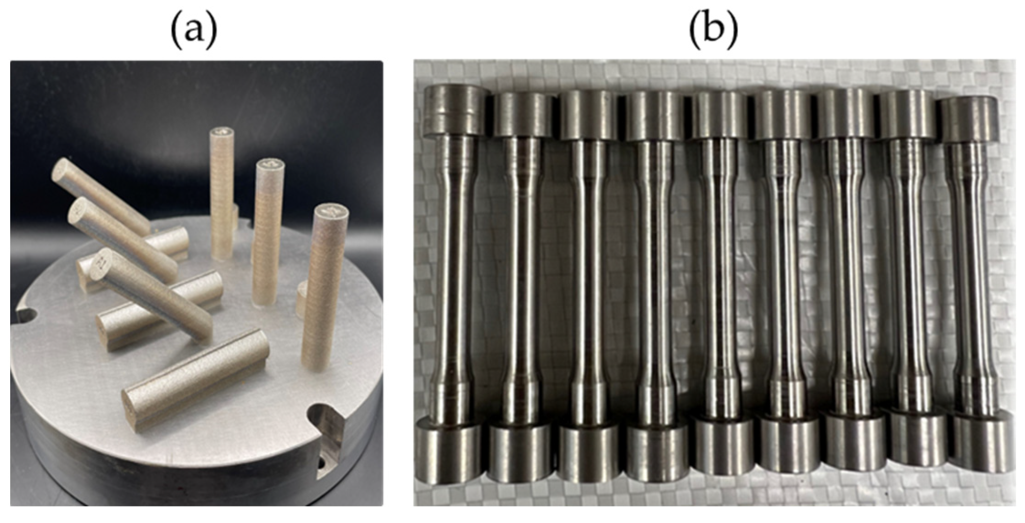
An LPBF machine (INTECH, SF1 iFusion150, Intech Additive Solutions Ltd., Bangalore, India) was utilized to process both alloys. The machine was equipped with a 500-watt ytterbium-fiber laser featuring a spot size of 80 ± 5 µm and a circular AISI 304 stainless steel build plate with a diameter of 150 mm. The base plate heater was set to 150 °C, which was maintained throughout the build process. The build chamber was kept in high-purity argon gas (Grade 5.0) atmosphere, to ensure that oxygen levels remained below 0.5 ppm. Using the process parameters defined in a previous process optimization study [16], cylindrical DSS and SDSS tensile bars (L 70 mm × Ø 11 mm) were produced, with relative densities exceeding 99.9%. The tensile bars were designed and manufactured so that enough clearance was ensured for machining to their final dimensions in accordance with ASTM E8/E8M-22 Standard Test Methods for Tension Testing of Metallic Materials [34] (Figure 2). Tensile samples were machined to the required dimensions using a lathe, ensuring precise geometry and a high-quality surface finish for accurate mechanical testing (Figure 3b). The impact of machining on the mechanical properties was considered to be negligible since the porosity was lower than 1% [35]. Three build orientations, horizontal 0° (H), diagonal 45° (A), and vertical 90° (V), were tested for each test case, as shown in Figure 3, where the direction of the longest edge of the bar defined the name of the orientation.
Test cases included one as-built and two post-heat treatments: (i) stress relief at 300 °C with dwell time of 4 h and (ii) high-temperature annealing at 1100 °C with dwell time of 1 h followed by water quenching. The ramp up temperature was set at 10 °C per minute for both heat treatments. In order to study all three build orientations in two heat treatment conditions, 27 test samples were produced (54 along with their duplicates). Two extra tensile bars were produced as duplicates for each test case to ensure repeatability and reduce deviations in the results.
Three builds were performed for each alloy, with each build plate containing nine samples, as shown in Figure 3a. Temperatures and times for heat treatment were selected based on a previous study [16] where solution annealing resulted in an austenite/ferrite ratio of 30/70 for DSS and 60/40 for SDSS. In the same study [15], it was also shown that stress relief annealing at 300 °C had no impact in the microstructure of DSS and SDSS as-built samples and no secondary phases were observed after both heat treatments. The as-built microstructure of both alloys was fully ferritic (~100%) with only some traces of grain boundary austenite in SDSS as-built microstructure. Heat treatments were conducted in a chamber furnace (THERMANSYS, BOX-AS20-1600, Thessaloniki, Greece), capable of reaching temperatures up to 1550 °C. Tensile bars were placed in crucibles to avoid contamination. Following heat treatments, the cylindrical bars were removed from the substrate via Electrical Discharge Machining (EDM) and machined to their final dimensions (Figure 3b). Uniaxial tensile tests were carried out using a 50 kN electromechanical universal test machine (Zwick/Roell, Z250 SN, Ulm, Germany) operating at a constant crosshead speed of 2 mm/min at ambient temperature. The pre-load was set at 100 N. The strain rate was calculated at approximately 2 × 10⁻³ s−1 based on Equation (1):
S t r a i n   R a t e = v L o
where v is the crosshead speed in mm/s and Lo is the gauge length in mm. Developing strains were simultaneously measured with digital image correlation (DIC) utilizing 12.3 MP cameras (Brasler, acA4112-20 um, Ahrensburg, Germany) mounted 450 mm from the specimen. Each specimen gauge section was airbrushed with a random black ink-on-white ink speckle pattern. This was necessary for the strain measurement with DIC, by tracking the displacement of speckle patterns between successive images captured during the test. DIC software (Vic-3D, version 10, Correlated Solutions Inc., Irmo, SC, USA) calculated the strain values at each point on the specimen’s surface.

2.3. Fracture Surface and Microstructure Examination

Once the samples were fractured, they were placed on a stage for subsequent SEM imaging of the fractured surfaces. In addition, using the same metallographic preparation as in [16], samples from the grip area of the tensile specimens were subjected to SEM microstructural analysis, thus validating the heat treatment effect. SEM analysis was performed on a Phenom G2 Xl Scanning Electron Microscope (Thermo Fisher Scientific Inc., Waltham, MA, USA). SEM images of the DSS A2 sample in the annealed and quenched condition were not taken, as this sample exhibited early yielding near the grip area during tensile testing.

3. Results

3.1. Mechanical Properties and Microstructure

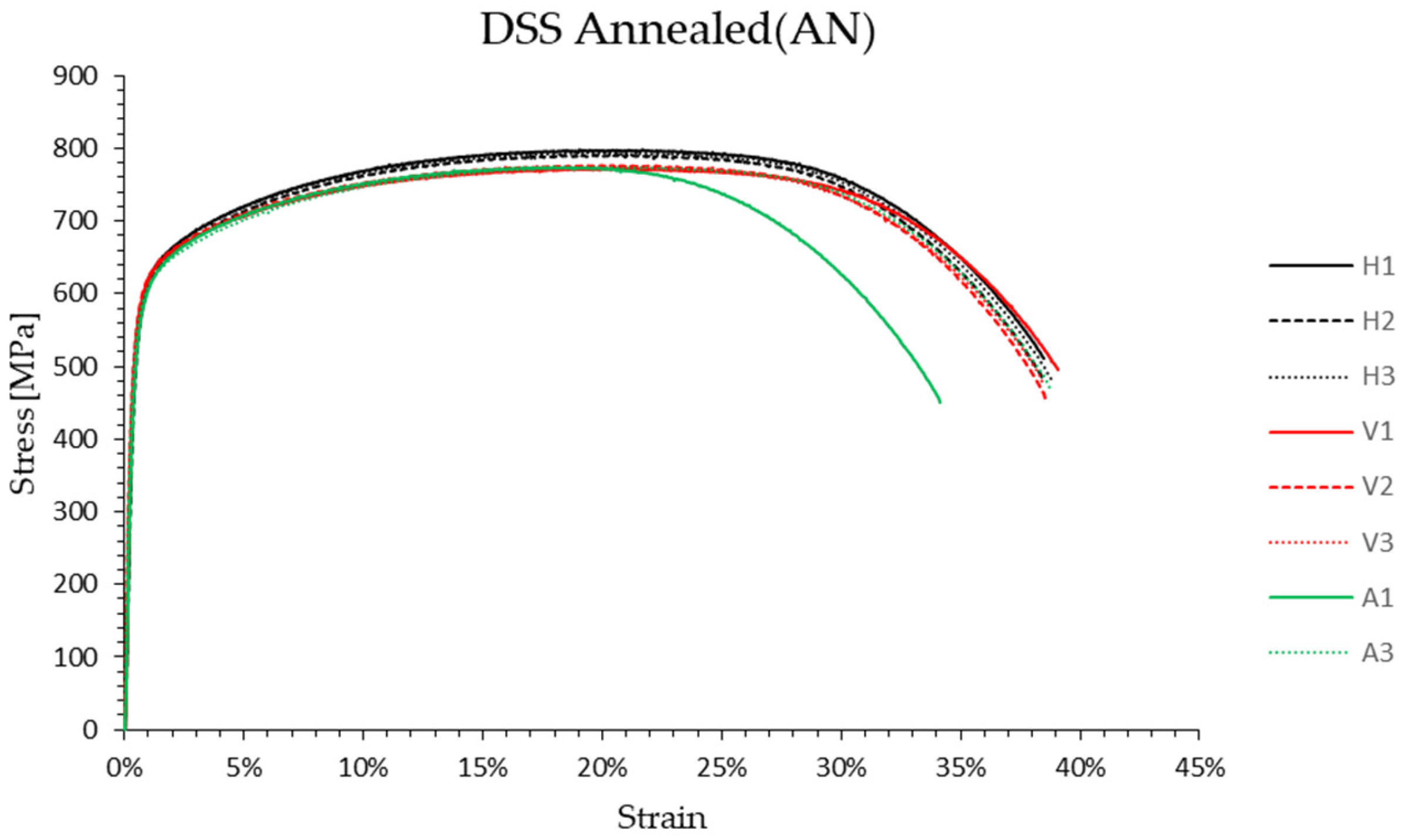
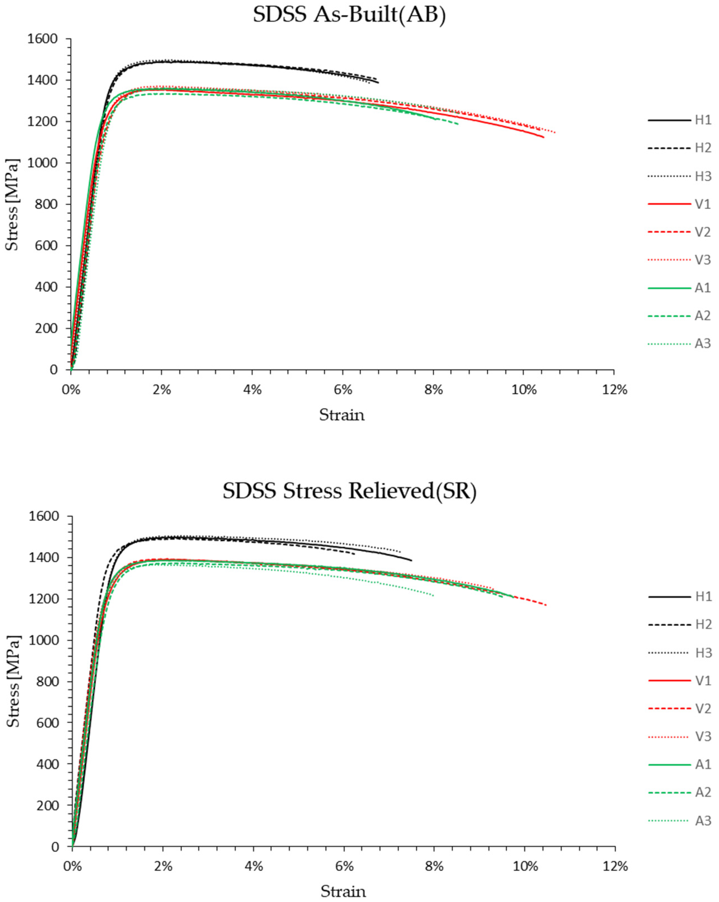
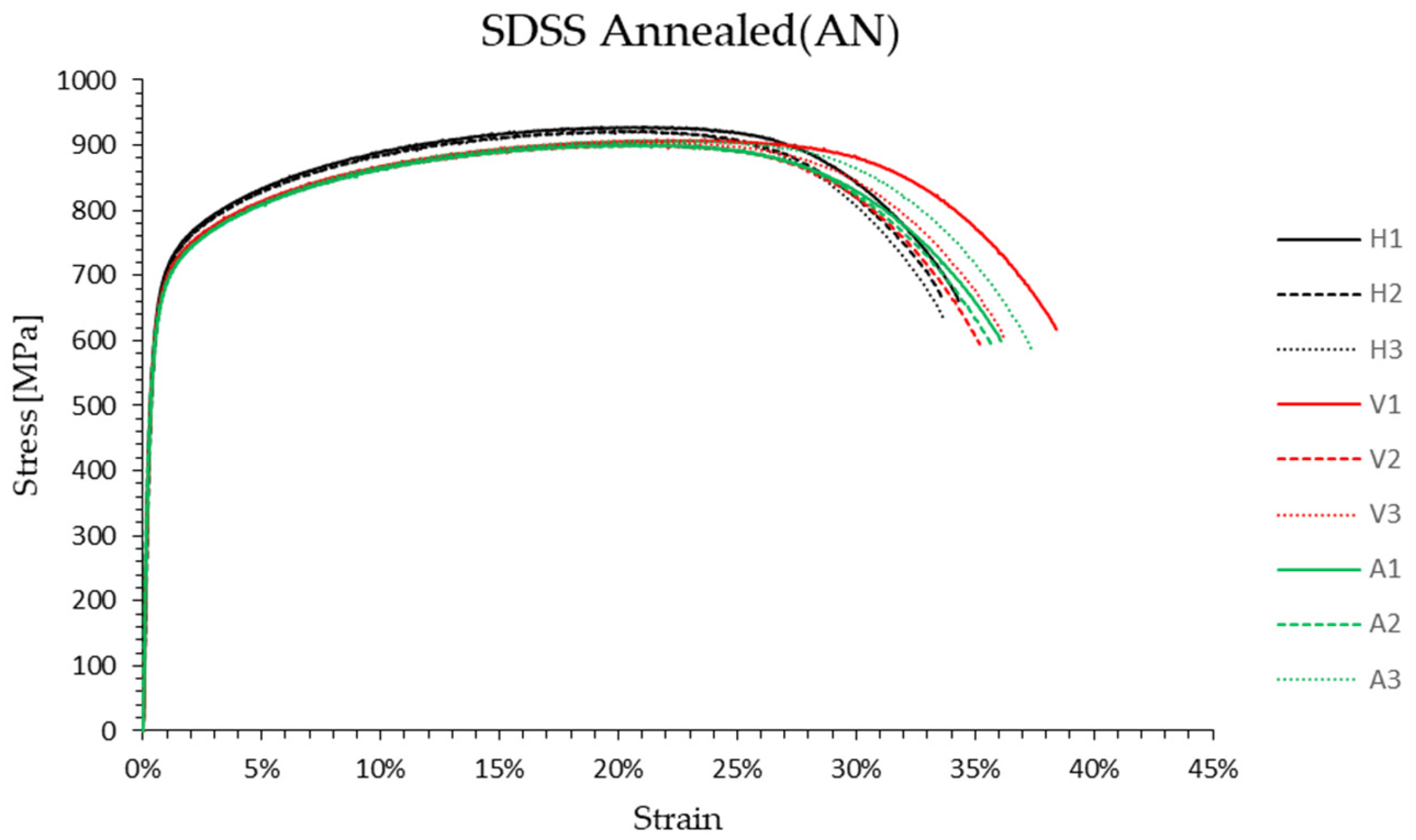
Figure 4 and Figure 5 show stress–strain curves for both alloys in all conditions and build orientations. A good repeatability was observed for each build orientation and process condition. The initial observation of the stress–strain curves of both alloys showed that the horizontal orientation exhibited the highest YS and UTS values, but a lower ductility compared to the other two (vertical and diagonal) in the as-built and stress relief conditions. In the annealed and water-quenched conditions, the stress–strain curves exhibited similar patterns for all build orientations in both alloys, with no clear indication of which orientation is the strongest. In addition, the EL of the as-built and stress-relieved specimens was lower than that of the annealed and water-quenched samples for both alloys. The main mechanical properties, namely YS 0.2%, UTS, and EL, were extracted from the curves and are summarized in Table 2.
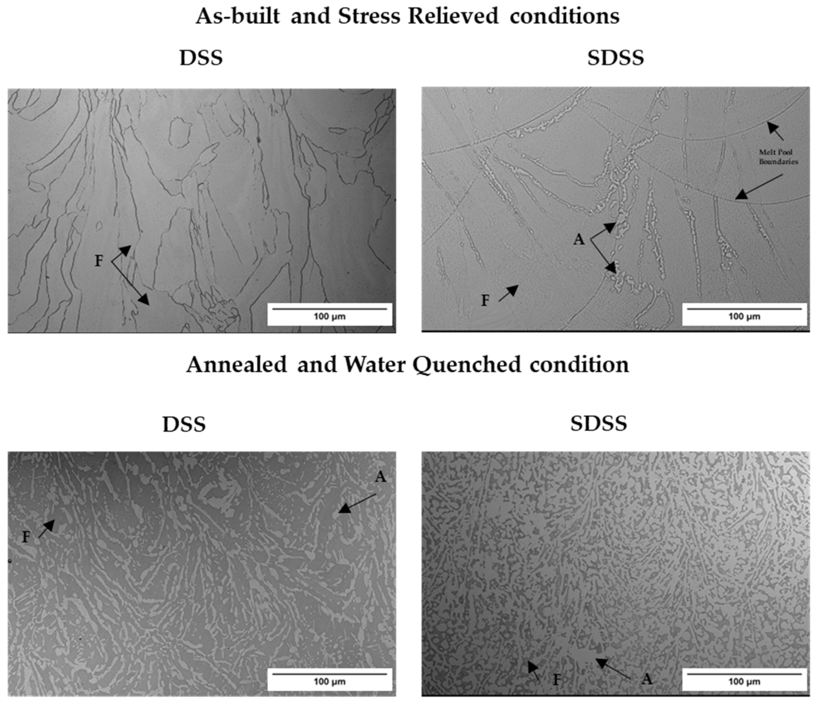
The SEM micrographs in Figure 6 illustrate representative microstructures of the grip area samples in three build conditions for both alloys. DSS samples, both in the as-built and stress-relieved states, displayed a fully ferritic microstructure, whereas SDSS samples exhibited in both conditions an almost fully ferritic microstructure with austenite present along grain boundaries. After annealing at 1100 °C for 1 h, both alloys demonstrated an increased austenite content, with SDSS showing the highest austenite percentage (60%).
Table 3 collates mechanical property data from the current and other studies for DSS and SDSS produced via LPBF as well as conventional manufacturing technologies.

3.2. Fractography

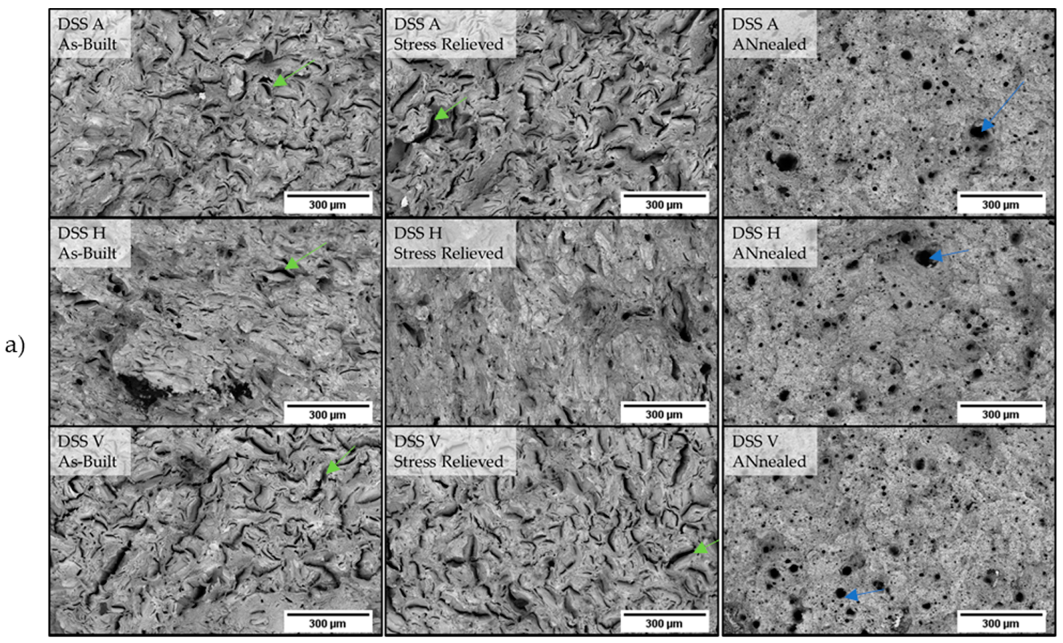
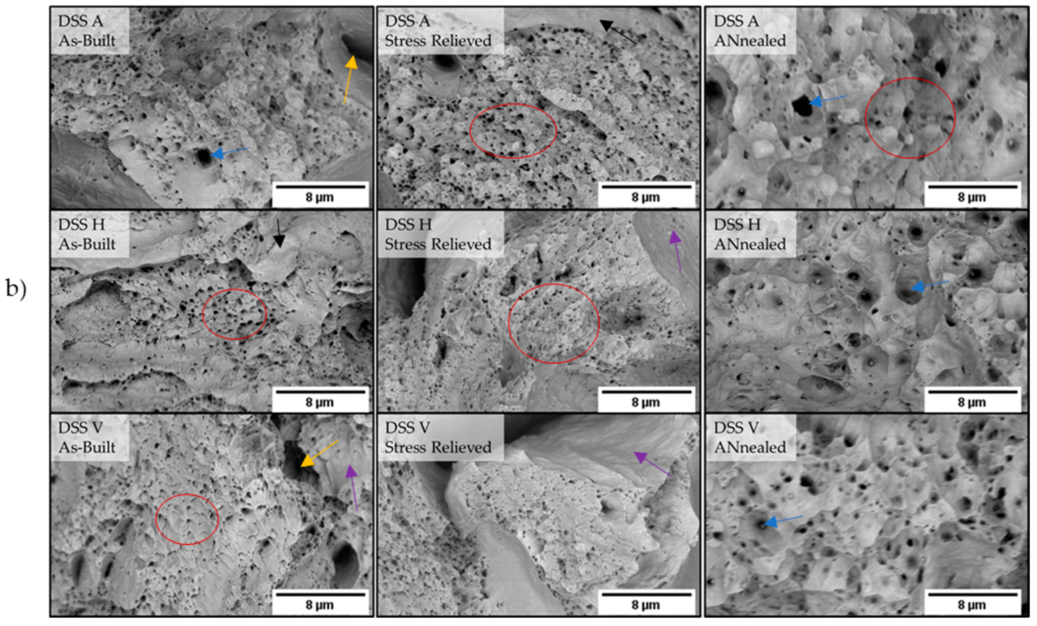
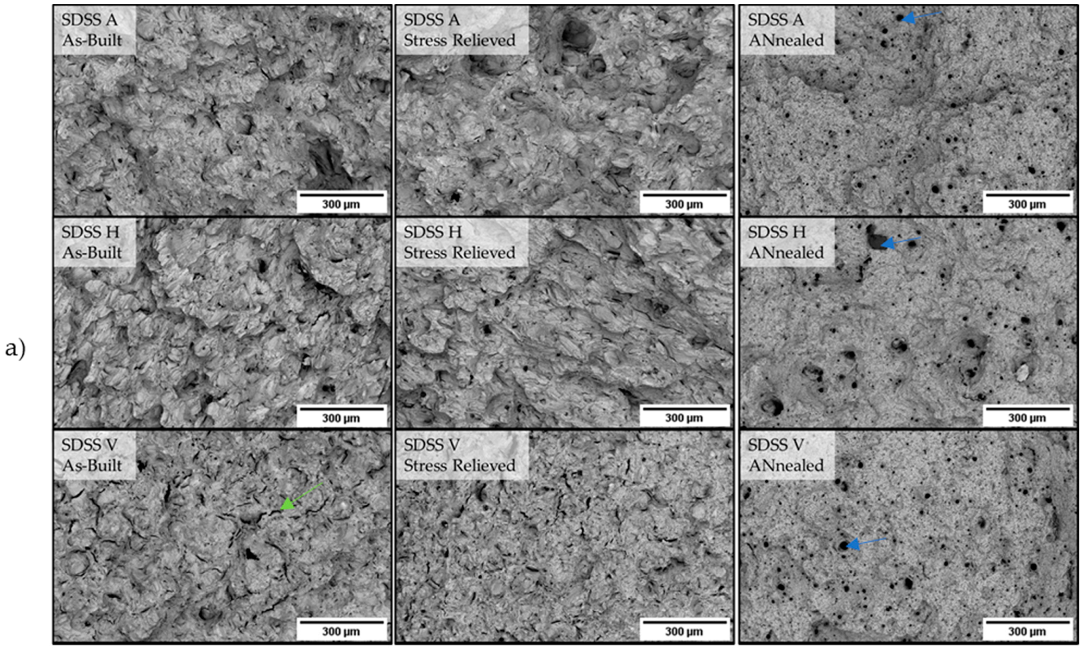
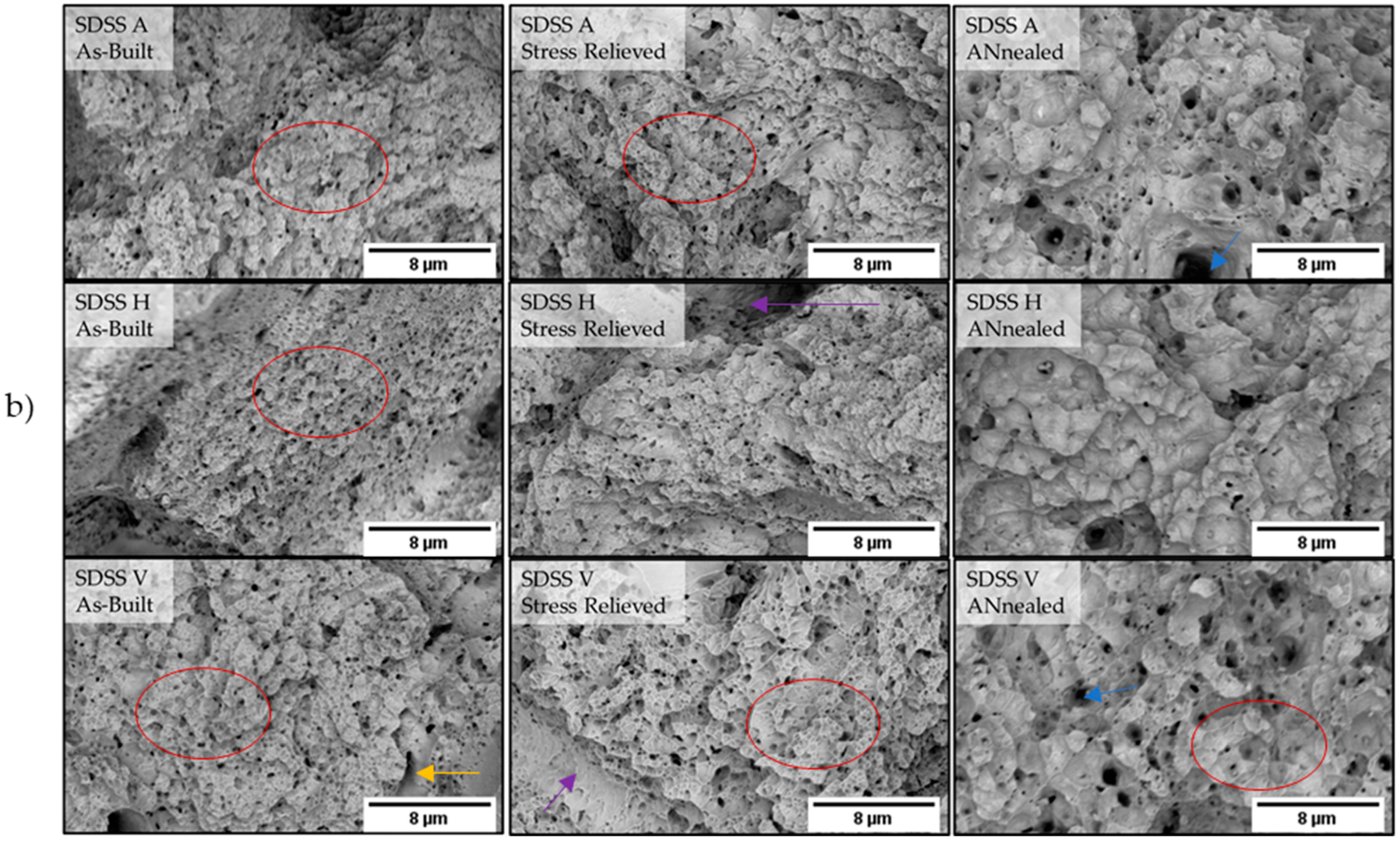
Figure 7 and Figure 8 illustrate areas of the fracture surfaces of DSS and SDSS in all three build conditions and three build orientations respectively.

4. Discussion

4.1. Effect of Heat Treatments

Stress relief annealing at 300 °C for 4 h showed no significant impact on the mechanical properties of both DSS and SDSS, which featured values similar to those in the as-built condition. The observed variations in mechanical properties between the two conditions were very small and fell within the measurement error range. High-temperature solution annealing followed by water quenching led to a further increase in EL by approximately 20%, accompanied by a decrease in UTS and YS by 200–300 MPa and 400–500 MPa, respectively, in all build orientations for the DSS alloy. In the case of SDSS, solution annealing followed by water quenching increased EL by approximately 30% and decreased UTS and YS by 450–570 MPa and 650–780 MPa, respectively, in all build orientations. Austenite formation and microstructure recrystallization are significant factors which triggered these significant changes of the mechanical properties in the annealed and quenched condition. Hengsbach et al. [9] and Nigon et al. [17] reported that solution annealing reduces the high dislocation density present in the microstructure of the as-built DSS samples. This, combined with austenite nucleation and grain recrystallization, contributes to the recovery of EL in the annealed and quenched condition. When comparing the two alloys in this study, the greater increase in EL and greater decrease in both UTS and YS are observed for SDSS after annealing and water quenching. The main reason is that SDSS has a higher austenite content (60%) as compared to DSS, which features up to 30% austenite (Figure 6) [16]. Kunz et al. substantiated the variation in mechanical properties between the two alloys by identifying a larger austenite content in the microstructure of SDSS (43.3%) compared to that of DSS (36.2%) following identical heat treatment procedures for the two alloys. Both Gargalis et al. [16] and Kunz et al. [25] attributed the higher austenite volume fraction in the annealed and quenched condition of SDSS to their higher content in austenite stabilizing elements (Ni, N) in this steel as compared to DSS. Divergences in the mechanical property values between DSS and SDSS are noticeable in the as-built condition. DSS exhibits nearly twice the EL but lower UTS by ≈300–400 MPa and lower YS by ≈200–300 MPa compared to SDSS. The reduced ductility and enhanced strength of the SDSS compared to DSS in the as-built condition are attributed to solid solution strengthening of the ferritic phase, owing to the higher content of alloying elements in SDSS as compared to DSS. This leads to a stronger ferritic microstructure with higher UTS and YS and lower EL, despite the presence of trace amounts of grain boundary austenite [16]. SDSS contains higher amounts of Mo and N compared to DSS, with both elements contributing positively to the overall strength of the alloy [39]. Several studies have reported precipitation of chromium nitride (Cr2N) in the as-built microstructure of DSS produced via LPBF via Transmission Electron Microscopy (TEM) studies [9,20,40]. Chromium nitrides precipitate as a consequence of nitrogen supersaturation within the ferrite, owing to rapid cooling and the enhanced nitrogen diffusion rate [41,42]. The presence of chromium nitrides enhances the hardness, UTS, and YS of the alloy while reducing its toughness and ductility [20,43]. SDSS may contain higher amounts of chromium nitride precipitates compared to DSS in the as-built condition, due to the higher nitrogen content in the former as compared to the latter [44]. This, consequently, may explain the observed lower EL and higher YS and UTS of the SDSS samples in the as-built condition. Additionally, it has been reported that nitrides dissolve upon solution annealing of DSS as-built samples, thus contributing to the recovery of ductility [20]. Other studies indicate that the generation of fine sub-micro-grains during the LPBF process improves the YS of as-built SS316L [45]. Gargalis et al. [16] observed sub-micro-grain zones near the melt pool and laser melt track boundaries only for SDSS but not DSS as-built microstructures. Therefore, the increased YS observed in as-built SDSS across all build orientations can be ascribed to the presence of sub-micro grain zones, as opposed to as-built DSS.

4.2. Effect of Build Orientations

The horizontally oriented samples showed the highest UTS and YS values for every processing condition (as-built, stress-relieved, annealed and quenched) for both alloys. Specifically, for the SDSS alloy, as-built horizontal samples exhibit UTS values 130–140 MPa higher than those of the other two build orientations. A similar difference is also observed for YS with values 140–150 MPa higher compared to vertical and diagonal samples. In the stress-relieved condition, SDSS samples built in the horizontal orientation showed UTS values 110–120 MPa higher and YS values 120–130 MPa higher than the UTS and YS values of the samples built in vertical and diagonal orientations. In both the as-built and stress-relieved state of the DSS alloy, the UTS values for the horizontal build orientation were 50–100 MPa higher, and the YS values were 30–100 MPa higher when compared to the UTS and YS values of the other two build orientations. The diagonal build orientation showed the lowest UTS and YS values for every processing condition (as-built, stress-relieved, annealed and quenched) for DSS, but not for SDSS, where the vertical build orientation exhibited the minimum YS value in the stress-relieved condition. In general, the diagonal and vertical build orientations exhibited very close UTS and YS values. The vertical build orientation showed the highest EL and the horizontal the lowest for the SDSS alloy in every processing condition (as-built, stress-relieved, annealed and quenched), whereas for DSS, the horizontal build orientation exhibited the highest EL values in the as-built and stress-relieved conditions. Specifically, in the case of SDSS, the horizontal build orientation displayed a 2–3% lower EL than that of the vertical build orientation. Conversely, for the DSS alloy, the horizontal build orientation demonstrated a 1–2% higher EL compared to the vertical build orientation. In the annealed and quenched conditions of both alloys, the horizontal build orientation showed a negligible increase of about 20 MPa in UTS and YS compared to the UTS and YS of the other two build orientations.
Components manufactured via additive manufacturing, such as LPBF, exhibit anisotropic mechanical properties due to the layer-wise building, rapid cooling rates, and resultant grain orientations. The preferred grain orientation across the build direction (epitaxial grain growth) will cause variable mechanical response based on the build orientation of the part [32,46]. LPBF samples manufactured horizontally exhibit higher mechanical properties than those built vertically [47]. The highest YS and UTS of DSS and SDSS as-built and stress-relieved samples in the horizontal build orientation can be explained by the grain size and shape the tensile load is applied on. Studies have shown that the grain size in the horizontal build orientation was smaller than that in the vertical build orientation for LPBF as-built SS316L [31]. Considering the Hall–Petch effect, horizontal samples can achieve a higher YS. Additionally, another study reported that the mechanical anisotropy of the as-built SS316L produced via LPBF should be attributed to differences in grain aspect ratio and grain orientation [48]. Nigon et al. [17] confirmed the microhardness anisotropy of DSS as-built samples manufactured via LPBF. The Vickers microhardness values perpendicular to the build orientation indicated higher hardness compared to those along the longitudinal build orientation. This was attributed to the fact that the grains are elongated along the build orientation, and therefore, the indenter force is applied to a smaller grain section perpendicular to the build direction (thus exhibiting higher stress/hardness) as compared to the longitudinal direction. After heat treatment, the grains become more equiaxed and the microhardness anisotropy disappears [17]. The solution annealing and water quenching resulted in a completely homogeneous and recrystallized duplex microstructure with an absence of melt pool boundaries and laser melt tracks [16] in all build orientations for both alloys. Furthermore, uniform grain size and shape were achieved in all build orientations through solution annealing heat treatment. As a result, DSS and SDSS exhibited isotropic mechanical behavior in the annealed and quenched state.

4.3. Comparisons of Mechanical Properties between Manufacturing Methods

The mechanical properties presented in this study for both alloys, as shown in Table 3, are better when compared to values found in the literature, in the as-built condition and the annealed condition followed by quenching. Papula et al. [24] reported mechanical properties for the DSS alloy in its as-built state, with nearly identical values to the ones found in the present study. This similarity can be explained by the fact that in both studies, samples with equal densities in the as-built condition were produced. Nigon et al. [17] reported an 18% lower EL compared to the annealed and quenched DSS alloy, despite applying an identical heat treatment protocol as in this study (annealing at 1100 °C for 1 h followed by water quenching). This disparity is attributed to the higher porosity levels detected in the samples of Nigon et al., resulting in premature necking upon tensile testing and subsequently reducing the overall elongation at break, despite their samples exhibiting a 15–20% higher austenite content. Mulhi et al. [19] demonstrated comparable EL but lower YS and UTS values than SDSS as-built alloy in this study. The decreased YS and UTS in Mulhi et al. [19] is attributed to the higher austenite content (10%) as compared to the SDSS as-built samples in the present study which contained approximately 1% austenite [16]. Interestingly, in both studies, the same EL was observed despite the difference in austenite content. A higher austenite content would typically lead to higher EL; however, variations in optimum processing parameters resulted in differing distributions of residual stresses among the samples, which may explain this discrepancy [49,50]. Xie et al. [18] reported lower UTS and higher YS values with a fully ferritic microstructure and 1% less porosity compared to the SDSS as-built samples presented in this study. The laser scanning strategy employed significantly influences the magnitude of residual stresses and the non-uniform anisotropic stress field [51] within the sample. Both Mulhi et al. [19] and Xie et al. [18] utilized different scanning strategies than the one employed in this study, which could further account for the observed differences in mechanical properties.
Only two studies have investigated the mechanical properties in both vertical and horizontal build orientations of DSS produced via LPBF and only in the annealed and quenched condition. Zhang et al. [27] measured the YS and UTS values of horizontal samples at 717 MPa and 912 MPa, respectively, while vertical samples featured 639 MPa YS and 859 MPa UTS. Furthermore, in the horizontal build orientation, EL was measured at 50.2%, whereas in the vertical build orientation, EL was 52.9%. The EL values reported by Zhang et al. [27] were superior to those measured in this study. Jeffs et al. [26] reported UTS (753–832 MPa) and YS (482–523 MPa) values similar to those of this study, for both vertical and horizontal build orientations, but they noted an extraordinarily high EL of 52.1% in the vertical build orientation, which is similar to the value reported by Zhang et al. [27]. The high EL values observed by Jeffs and Zhang, are attributed to a different heat treatment procedure resulting in a higher austenite content in the microstructure. Jeffs et al. [26] measured approximately 46.6% austenite in the microstructure, while Zhang et al. [27] measured 50%, compared to the DSS annealed and quenched samples in this study, which exhibited approximately 30% austenite in the microstructure [16].
Considering that traditionally manufactured DSS and SDSS parts typically have a duplex microstructure, it is appropriate to compare them with the annealed and quenched samples in this study. Cold-rolled and annealed SDSS [38] featured approximately 100 MPa higher YS compared to the annealed and quenched SDSS in this study. The UTS of cold-rolled and annealed SDSS was the same as that of the SDSS annealed and quenched samples in this study. In addition, Lakhdari et al. [38] produced ultrafine microstructures that demonstrated 150 MPa higher YS and 100 MPa higher UTS than the YS and UTS of the SDSS annealed and quenched samples in this study. However, both cases by Lakhdari et al. [38] were more brittle than the SDSS annealed and quenched samples, as the EL was approximately 15–20% lower. As-cast DSS [37], even after annealing and quenching, exhibited lower mechanical properties than the annealed and quenched DSS samples in this study. Hot-rolled DSS [37] exhibited almost identical mechanical properties but still lower than that of the annealed and quenched DSS samples. Cold-rolled DSS [37] demonstrated YS and UTS approximately 300 MPa higher in comparison to the annealed and quenched DSS samples. However, cold-rolled DSS exhibited an approximately 20% lower EL compared to the annealed and quenched DSS samples. Cold-rolled DSS exhibited lower EL in comparison to annealed and quenched SDSS and DSS. Cold rolling refines the microstructure by decreasing the grain size but induces mechanical residual stresses due to plastic deformation in the material, which effectively lowers EL. The slower solidification rate of DSS and SDSS during casting [52] results in a larger grain size and reduced thermal residual stresses compared to the finer LPBF microstructures.

4.4. Fractographic Analysis

DSS as-built and stress-relieved samples have shown similar fracture patterns in the vertical and diagonal build orientations. Numerous secondary cracks are observed around the dimple areas, and upon closer examination at higher magnifications, these cracks exhibit cleavage facets along their walls. It appears that the formation of these cracks is associated with pre-existing porosity. Therefore, the DSS as-built and stress relieved samples in vertical and diagonal build orientations exhibited a mixed brittle–ductile fracture. A similar fracture mode was observed by Haghdadi et al. [20] who also showed a mixed brittle–ductile fracture in as-built DSS samples, presumably attributed to the fully ferritic microstructure and the presence of nitrides as well as process-induced residual stresses and sample porosity. In the case of the as-built and stress-relieved SDSS samples built in diagonal and horizontal orientations, no secondary cracks were observed. However, the as-built and stress-relieved SDSS samples built in the vertical orientation showed a few secondary cracks surrounding the dimple areas. Dimples of SDSS as-built and stress-relieved samples in vertical and diagonal build orientations were fine and shallow compared to those of DSS in as-built and stress-relieved conditions built in vertical and diagonal orientations.
Pores and defects in the microstructures are crack initiation sites [29] and can result in premature sample rupture. However, it is often the type of pores, rather than their quantity, that plays the most significant role in the mechanical properties/response. Lack-of-fusion pores are commonly observed to have a more adverse impact on tensile properties compared to gas or keyhole pores [53]. Especially for vertical samples, lack-of-fusion pores can easily grow due to the load direction causing crack initiation [54]. These cracks swiftly connect with adjacent pores, leading to rapid coalescence and premature fracture with minimal necking [55].
Overall, the SDSS as-built and stress-relieved samples built in vertical and diagonal orientations exhibited fewer cleavage facets and more dimples compared to DSS as-built and stress-relieved samples in the same build orientations. DSS demonstrated total rupture at a higher EL of 16–19%, in contrast to the rupture value of SDSS, which occurred at 8–11% EL. This can be attributed to the fact that the secondary cracks in DSS arise slightly away from the point of total rupture during necking, having minimal impact on the overall elongation of the alloy. Pore growth and coalescence typically take place during the necking phase of a tensile test, occurring after the UTS is reached. As a result, initial porosity levels have a fundamental impact on YS and UTS, whereas porosity growth and coalescence, along with the initiation and propagation of secondary cracks, affect total elongation [56]. The dramatic increase in pore fraction upon necking indicates that the ease of pore growth, coalescence, and porosity-assisted crack initiation and propagation involves interaction with the matrix. Therefore, the elongation at fracture in a more ductile or tougher microstructure might be less susceptible to the presence of necking-induced porosity and secondary cracks [57]. In addition, as discussed in Section 4.1 the higher EL in DSS is associated with a lower level of solid solution strengthening, owing to lower wt% in alloying additions, as well as the reduced presence of chromium nitrides in its as-built microstructure, in contrast to SDSS.
DSS (2205) horizontal samples in as-built and stress-relieved conditions demonstrated a quasi-ductile fracture with the presence of cleavage facets interrupting the dimple zones, which are also evident for the vertical and diagonal samples in the higher-magnification micrographs (Figure 7b). Conversely, SDSS has shown more dimple fracture with less cleavage facets. The lack of secondary cracks in the fracture surfaces of DSS and SDSS as-built and stress-relieved samples in the horizontal build orientation can be explained by the low porosity levels in the samples or by the fact that the lack-of-fusion pores rarely interact with neighboring pores and cracks do not propagate during necking [55]. The SDSS samples built horizontally, both in their as-built and stress-relieved states, displayed a reduced EL compared to the vertical and diagonal build orientation samples. This can be attributed to microstructural factors, specifically grain shape and size, as discussed in Section 4.2. In contrast, the DSS samples built horizontally, in their as-built and stress-relieved state, demonstrated an increased EL relative to the vertical and diagonal build orientation samples. This increase can be attributed to the presence of secondary cracks on the fracture surface formed during necking, consequently diminishing EL. The fracture surface features are remarkably consistent across all build orientations in both DSS and SDSS annealed and quenched samples, indicating a fully ductile fracture with the absence of cleavage facets and lack-of-fusion pores. In this condition, gas pores were the only type of porosity observed on the fracture surface of both DSS and SDSS samples. Studies by Xie et al. [18] and Papula et al. [24] have highlighted that SDSS and DSS, in the annealed and quenched state, typically exhibit a fracture dominated by dimples.

5. Conclusions

In this work, the effect of heat treatments and build orientations on the mechanical properties of 2205 DSS and 2507 SDSS alloys fabricated by LPBF were investigated. Additionally, the fracture surfaces of the tensile samples have been assessed and the main conclusions are listed below:
  • DSS and SDSS alloys manufactured by LPBF exhibit better mechanical properties when compared with existing literature values for parts produced either by LPBF or by conventional manufacturing (as-cast, hot-rolled, and cold-rolled).
  • DSS and SDSS in the as-built state feature high YS and UTS (greater than 1000 Mpa) accompanied by low EL (lower than 20%) due to their fully ferritic microstructure. The higher alloying element content in SDSS leads to superior YS and UTS but lower elongation (EL) compared to DSS.
  • Stress relief annealing at 300 °C does not significantly alter mechanical properties of both alloys, as the microstructure does not change.
  • Solution annealing and water quenching at 1100 °C for 1 h increases ductility (greater than 34%) but reduces the YS and UTS (lower than 950 MPa) of the DSS and SDSS as-built samples, attributed to austenite nucleation and growth, recrystallized microstructure, and the absence of secondary phases.
  • Horizontal build orientation results in the highest YS and UTS across all build conditions, surpassing vertical orientation values. Grain size and shape affect how the tensile load is applied, leading to higher strength in horizontally built samples. However, vertical orientation shows the highest EL in all build conditions for SDSS, while DSS shows varied behavior depending on the condition. Diagonal and vertical build orientations showed similar mechanical properties for both alloys in all build conditions due to their similar grain sizes and shapes. DSS and SDSS alloys manifest isotropic mechanical behavior in the annealed and quenched condition due to their homogeneous recrystallized microstructure with uniform grain size and shape in all build conditions.
  • Fractographic analysis of tensile test samples reveals a quasi-ductile fracture of the as-built and stress-relieved samples for both alloys. In addition, DSS and SDSS annealed and quenched samples demonstrate a fully ductile microstructure with fine dimples and absence of cleavage facets. Secondary cracks in vertical and diagonal DSS samples (as-built and stress-relieved) are induced by pre-existing lack-of fusion and gas pores during necking. Gas pores are consistently found in all annealed and quenched DSS and SDSS fractured samples. Horizontal samples (as-built and stress-relieved) exhibit lower porosity on the fracture surface compared to vertical and diagonal samples in the same conditions. Pores on the fracture surface serve as crack initiation points.

Author Contributions

Conceptualization, L.K. and L.G.; Methodology, L.K., L.G., M.J. and J.S.G.; Formal analysis, L.K. and L.G.; Investigation, L.K. and L.G.; Data curation, L.K., L.G., M.J. and J.S.G.; Writing—review and editing L.K., L.G., S.D. and E.K.K.; funding acquisition, S.D. and E.K.K.; Supervision, S.D. and E.K.K. All authors have read and agreed to the published version of the manuscript.

Funding

This research was funded by the European Commission under the HORIZON2020 Framework Programme Grant Agreement no. 952869. This research was conducted within the framework of Nanomecommons project. https://www.nanomecommons.net/ (accessed on 16 July 2024).

Data Availability Statement

The raw/processed data required to reproduce these findings cannot be shared at this time, as the data also form part of an ongoing study.

Conflicts of Interest

The authors declare no conflict of interest. The funders had no role in the design of the study; in the collection, analysis or interpretation of data; in the writing of the manuscript; or in the decision to publish the results.

References

  1. Stainless, T. Practical Guidelines for the Fabrication of Duplex Stainless Steels; IMOA (International Molybdenum Association): London, UK, 2014; ISBN 9781907470097. [Google Scholar]
  2. Fargas, G.; Akdut, N.; Anglada, M.; Mateo, A. Microstructural Evolution during Industrial Rolling of a Duplex Stainless Steel. ISIJ Int. 2008, 48, 1596–1602. [Google Scholar] [CrossRef]
  3. Gowthaman, P.S.; Jeyakumar, S.; Saravanan, B.A. Machinability and Tool Wear Mechanism of Duplex Stainless Steel—A Review. Mater. Today Proc. 2019, 26, 1423–1429. [Google Scholar] [CrossRef]
  4. Fritz, J. Practical Guide to Using Duplex Stainless Steels (10044), 2nd ed.; Moe, G., Ed.; Nickel Institute: Toronto, ON, Canada, 2020. [Google Scholar]
  5. Liu, Q.; Wang, G.; Qiu, C. On the Role of Dynamic Grain Movement in Deformation and Mechanical Anisotropy Development in a Selectively Laser Melted Stainless Steel. Addit. Manuf. 2020, 35, 101329. [Google Scholar] [CrossRef]
  6. Chowdhury, S.; Yadaiah, N.; Prakash, C.; Ramakrishna, S.; Dixit, S.; Gupta, L.R.; Buddhi, D. Laser Powder Bed Fusion: A State-of-the-Art Review of the Technology, Materials, Properties & Defects, and Numerical Modelling. J. Mater. Res. Technol. 2022, 20, 2109–2172. [Google Scholar] [CrossRef]
  7. Santonocito, D.; Fintová, S.; Di Cocco, V.; Iacoviello, F.; Risitano, G.; D’Andrea, D. Comparison on Mechanical Behavior and Microstructural Features between Traditional and AM AISI 316L. Fatigue Fract. Eng. Mater. Struct. 2023, 46, 379–395. [Google Scholar] [CrossRef]
  8. Cobbinah, P.V.; Nzeukou, R.A.; Onawale, O.T.; Matizamhuka, W.R. Laser Powder Bed Fusion of Potential Superalloys: A Review. Metals 2021, 11, 58. [Google Scholar] [CrossRef]
  9. Hengsbach, F.; Koppa, P.; Duschik, K.; Holzweissig, M.J.; Burns, M.; Nellesen, J.; Tillmann, W.; Tröster, T.; Hoyer, K.P.; Schaper, M. Duplex Stainless Steel Fabricated by Selective Laser Melting—Microstructural and Mechanical Properties. Mater. Des. 2017, 133, 136–142. [Google Scholar] [CrossRef]
  10. Islam, M.M.; Bayati, P.; Nematollahi, M.; Jahadakbar, A.; Elahinia, M.; Haghshenas, M. Strain Rate Dependent Micromechanical Properties of NiTi Shape Memory Alloys: Laser Powder Bed Fusion versus Casting. Forces Mech. 2021, 5, 100055. [Google Scholar] [CrossRef]
  11. Rafi, H.K.; Starr, T.L.; Stucker, B.E. A Comparison of the Tensile, Fatigue, and Fracture Behavior of Ti-6Al-4V and 15-5 PH Stainless Steel Parts Made by Selective Laser Melting. Int. J. Adv. Manuf. Technol. 2013, 69, 1299–1309. [Google Scholar] [CrossRef]
  12. Nilsson, J.O. Super Duplex Stainless Steels. Mater. Sci. Technol. 1992, 8, 685–700. [Google Scholar] [CrossRef]
  13. Steiner Petrovič, D.; Pirnat, M.; Klančnik, G.; Mrvar, P.; Medved, J. The Effect of Cooling Rate on the Solidification and Microstructure Evolution in Duplex Stainless Steel: A DSC Study. J. Therm. Anal. Calorim. 2012, 109, 1185–1191. [Google Scholar] [CrossRef]
  14. Narasimharaju, S.R.; Zeng, W.; See, T.L.; Zhu, Z.; Scott, P.; Jiang, X.; Lou, S. A Comprehensive Review on Laser Powder Bed Fusion of Steels: Processing, Microstructure, Defects and Control Methods, Mechanical Properties, Current Challenges and Future Trends. J. Manuf. Process. 2022, 75, 375–414. [Google Scholar] [CrossRef]
  15. David, S.A.; Vitek, J.M.; Hebble, T.L. Effect of Rapid Solidification on Stainless Steel Weld Metal Microstructures and Its Implications on the Schaeffler Diagram. Weld. J. 1987, 66, 289-s–300-s. [Google Scholar]
  16. Gargalis, L.; Karavias, L.; Graff, J.S.; Diplas, S.; Koumoulos, E.P.; Karaxi, E.K. A Comparative Investigation of Duplex and Super Duplex Stainless Steels Processed through Laser Powder Bed Fusion. Metals 2023, 13, 1897. [Google Scholar] [CrossRef]
  17. Nigon, G.N.; Burkan Isgor, O.; Pasebani, S. The Effect of Annealing on the Selective Laser Melting of 2205 Duplex Stainless Steel: Microstructure, Grain Orientation, and Manufacturing Challenges. Opt. Laser Technol. 2021, 134, 106643. [Google Scholar] [CrossRef]
  18. Xie, C.; Li, B.; Liu, G.; Liu, J.; Ying, H.; Li, D.; Wang, S.; Wang, L. Study on the Effect of Solution Treatment on Mechanical and Corrosion Properties of SAF 2507DSS Produced by LPBF. J. Mater. Res. Technol. 2023, 26, 2070–2081. [Google Scholar] [CrossRef]
  19. Mulhi, A.; Dehgahi, S.; Waghmare, P.; Qureshi, A.J. Process Parameter Optimization of 2507 Super Duplex Stainless Steel Additively Manufactured by the Laser Powder Bed Fusion Technique. Metals 2023, 13, 725. [Google Scholar] [CrossRef]
  20. Haghdadi, N.; Ledermueller, C.; Chen, H.; Chen, Z.; Liu, Q.; Li, X.; Rohrer, G.; Liao, X.; Ringer, S.; Primig, S. Evolution of Microstructure and Mechanical Properties in 2205 Duplex Stainless Steels during Additive Manufacturing and Heat Treatment. Mater. Sci. Eng. A 2022, 835, 142695. [Google Scholar] [CrossRef]
  21. Llorca-Isern, N.; López-Luque, H.; López-Jiménez, I.; Biezma, M.V. Identification of Sigma and Chi Phases in Duplex Stainless Steels. Mater. Charact. 2016, 112, 20–29. [Google Scholar] [CrossRef]
  22. Di Cocco, V.; Iacoviello, F.; Ischia, G. Duplex Stainless Steels “475 °C Embrittlement”: Influence of the Chemical Composition on the Fatigue Crack Propagation. Procedia Struct. Integr. 2017, 3, 299–307. [Google Scholar] [CrossRef]
  23. Knyazeva, M.; Pohl, M. Duplex Steels. Part II: Carbides and Nitrides. Metallogr. Microstruct. Anal. 2013, 2, 343–351. [Google Scholar] [CrossRef]
  24. Papula, S.; Song, M.; Pateras, A.; Chen, X.B.; Brandt, M.; Easton, M.; Yagodzinskyy, Y.; Virkkunen, I.; Hänninen, H. Selective Laser Melting of Duplex Stainless Steel 2205: Effect of Post-Processing Heat Treatment on Microstructure, Mechanical Properties, and Corrosion Resistance. Materials 2019, 12, 2468. [Google Scholar] [CrossRef] [PubMed]
  25. Kunz, J.; Boontanom, A.; Herzog, S.; Suwanpinij, P.; Kaletsch, A.; Broeckmann, C. Influence of Hot Isostatic Pressing Post-Treatment on the Microstructure and Mechanical Behavior of Standard and Super Duplex Stainless Steel Produced by Laser Powder Bed Fusion. Mater. Sci. Eng. A 2020, 794, 139806. [Google Scholar] [CrossRef]
  26. Jeffs, S.; Douglas, R.; Beard, W.; Coleman, M.; Adams, J.; Jones, T.; Poole, D.; Lancaster, R. Characterising the High Temperature Tensile Behaviour of Laser Powder Bed Fused Duplex Stainless Steel 2205 Using the Small Punch Test. Mater. Charact. 2022, 189, 111953. [Google Scholar] [CrossRef]
  27. Zhang, J.; Zhu, H.; Xi, X.; Li, X.; Xiao, Z. Anisotropic Response in Mechanical and Corrosion Performances of UNS S31803 Duplex Stainless Steel Fabricated by Laser Powder Bed Fusion. J. Mater. Res. Technol. 2023, 26, 4860–4870. [Google Scholar] [CrossRef]
  28. Somlo, K.; Poulios, K.; Funch, C.V.; Niordson, C.F. Anisotropic Tensile Behaviour of Additively Manufactured Ti-6Al-4V Simulated with Crystal Plasticity. Mech. Mater. 2021, 162, 104034. [Google Scholar] [CrossRef]
  29. Tang, M.; Pistorius, P.C. Anisotropic Mechanical Behavior of AlSi10Mg Parts Produced by Selective Laser Melting. Jom 2017, 69, 516–522. [Google Scholar] [CrossRef]
  30. Pitrmuc, Z.; Šimota, J.; Beránek, L.; Mikeš, P.; Andronov, V.; Sommer, J.; Holešovský, F. Mechanical and Microstructural Anisotropy of Laser Powder Bed Fusion 316L Stainless Steel. Materials 2022, 15, 551. [Google Scholar] [CrossRef] [PubMed]
  31. Kong, D.; Ni, X.; Dong, C.; Zhang, L.; Man, C.; Cheng, X.; Li, X. Anisotropy in the Microstructure and Mechanical Property for the Bulk and Porous 316L Stainless Steel Fabricated via Selective Laser Melting. Mater. Lett. 2019, 235, 1–5. [Google Scholar] [CrossRef]
  32. Alfieri, V.; Giannella, V.; Caiazzo, F.; Sepe, R. Influence of Position and Building Orientation on the Static Properties of LPBF Specimens in 17-4 PH Stainless Steel. Forces Mech. 2022, 8, 100108. [Google Scholar] [CrossRef]
  33. Hovig, E.W.; Azar, A.S.; Solberg, K.; Sørby, K. An Investigation of the Anisotropic Properties of Heat-Treated Maraging Steel Grade 300 Processed by Laser Powder Bed Fusion. Int. J. Adv. Manuf. Technol. 2021, 114, 1359–1372. [Google Scholar] [CrossRef]
  34. ASTM E8/E8M-22; Standard Test Methods for Tension Testing of Metallic Materials. ASTM: West Conshohocken, PA, USA, 2010.
  35. Gong, H.; Rafi, K.; Gu, H.; Janaki Ram, G.D.; Starr, T.; Stucker, B. Influence of Defects on Mechanical Properties of Ti-6Al-4V Components Produced by Selective Laser Melting and Electron Beam Melting. Mater. Des. 2015, 86, 545–554. [Google Scholar] [CrossRef]
  36. Saeidi, K.; Kevetkova, L.; Lofaj, F.; Shen, Z. Novel Ferritic Stainless Steel Formed by Laser Melting from Duplex Stainless Steel Powder with Advanced Mechanical Properties and High Ductility. Mater. Sci. Eng. A 2016, 665, 59–65. [Google Scholar] [CrossRef]
  37. S Ghosh, S.K.; Mondal, S. Mondal Effect Of Heat Treatment On Microstructure And Mechanical Properties of Duplex Stainless Steel. Trans. Indian Inst. Met. 2008, 61, 33–37. [Google Scholar] [CrossRef]
  38. Lakhdari, M.A.; Krajcarz, F.; Mithieux, J.D.; Van Landeghem, H.P.; Veron, M. Strength Enhancement of Superduplex Stainless Steel Using Thermomechanical Processing. Metals 2021, 11, 1094. [Google Scholar] [CrossRef]
  39. Chail, G.; Kangas, P. Super and Hyper Duplex Stainless Steels: Structures, Properties and Applications. Procedia Struct. Integr. 2016, 2, 1755–1762. [Google Scholar] [CrossRef]
  40. Raffeis, I.; Vroomen, U.; Adjei-Kyeremeh, F.; Großmann, D.; Hammelrath, H.; Westhoff, E.; Bremen, S.; Boscolo Bozza, D.; Bührig-Polaczek, A. Comparative Investigations into Microstructural and Mechanical Properties of As-Cast and Laser Powder Bed Fusion (LPBF) Fabricated Duplex Steel (1.4517). Materwiss. Werksttech. 2020, 51, 432–444. [Google Scholar] [CrossRef]
  41. Ramirez, A.J.; Brandi, S.D.; Lippold, J.C. Secondary Austenite and Chromium Nitride Precipitation in Simulated Heat Affected Zones of Duplex Stainless Steels. Sci. Technol. Weld. Join. 2004, 9, 301–313. [Google Scholar] [CrossRef]
  42. Liou, H.Y.; Hsieh, R.I.; Tsai, W.T. Microstructure and Pitting Corrosion in Simulated Heat-Affected Zones of Duplex Stainless Steels. Mater. Chem. Phys. 2002, 74, 33–42. [Google Scholar] [CrossRef]
  43. Migiakis, K.; Papadimitriou, G.D. Effect of Nitrogen and Nickel on the Microstructure and Mechanical Properties of Plasma Welded UNS S32760 Super-Duplex Stainless Steels. J. Mater. Sci. 2009, 44, 6372–6383. [Google Scholar] [CrossRef]
  44. Wang, H.; Wang, A.; Li, C.; Yu, X.; Xie, J.; Liu, C. Effect of Secondary-Phase Precipitation on Mechanical Properties and Corrosion Resistance of 00Cr27Ni7Mo5N Hyper-Duplex Stainless Steel during Solution Treatment. Materials 2022, 15, 7533. [Google Scholar] [CrossRef] [PubMed]
  45. Wang, Y.M.; Voisin, T.; McKeown, J.T.; Ye, J.; Calta, N.P.; Li, Z.; Zeng, Z.; Zhang, Y.; Chen, W.; Roehling, T.T.; et al. Additively Manufactured Hierarchical Stainless Steels with High Strength and Ductility. Nat. Mater. 2018, 17, 63–70. [Google Scholar] [CrossRef] [PubMed]
  46. Kunze, K.; Etter, T.; Grässlin, J.; Shklover, V. Texture, Anisotropy in Microstructure and Mechanical Properties of IN738LC Alloy Processed by Selective Laser Melting (SLM). Mater. Sci. Eng. A 2015, 620, 213–222. [Google Scholar] [CrossRef]
  47. Kok, Y.; Tan, X.P.; Wang, P.; Nai, M.L.S.; Loh, N.H.; Liu, E.; Tor, S.B. Anisotropy and Heterogeneity of Microstructure and Mechanical Properties in Metal Additive Manufacturing: A Critical Review. Mater. Des. 2018, 139, 565–586. [Google Scholar] [CrossRef]
  48. Im, Y.D.; Kim, K.H.; Jung, K.H.; Lee, Y.K.; Song, K.H. Anisotropic Mechanical Behavior of Additive Manufactured AISI 316L Steel. Metall. Mater. Trans. A Phys. Metall. Mater. Sci. 2019, 50, 2014–2021. [Google Scholar] [CrossRef]
  49. Mercelis, P.; Kruth, J.P. Residual Stresses in Selective Laser Sintering and Selective Laser Melting. Rapid Prototyp. J. 2006, 12, 254–265. [Google Scholar] [CrossRef]
  50. Wu, A.S.; Brown, D.W.; Kumar, M.; Gallegos, G.F.; King, W.E. An Experimental Investigation into Additive Manufacturing-Induced Residual Stresses in 316L Stainless Steel. Metall. Mater. Trans. A Phys. Metall. Mater. Sci. 2014, 45, 6260–6270. [Google Scholar] [CrossRef]
  51. Robinson, J.; Ashton, I.; Fox, P.; Jones, E.; Sutcliffe, C. Determination of the Effect of Scan Strategy on Residual Stress in Laser Powder Bed Fusion Additive Manufacturing. Addit. Manuf. 2018, 23, 13–24. [Google Scholar] [CrossRef]
  52. Liao, L. Ferrite Percentage Prediction of Duplex Stainless Steels as a Function of Cooling Rates. Ph.D. Thesis, Iowa State University, Ames, IA, USA, 2018. [Google Scholar]
  53. Kan, W.H.; Chiu, L.N.S.; Lim, C.V.S.; Zhu, Y.; Tian, Y.; Jiang, D.; Huang, A. A Critical Review on the Effects of Process-Induced Porosity on the Mechanical Properties of Alloys Fabricated by Laser Powder Bed Fusion. J. Mater. Sci. 2022, 57, 9818–9865. [Google Scholar] [CrossRef]
  54. Ronneberg, T.; Davies, C.M.; Hooper, P.A. Revealing Relationships between Porosity, Microstructure and Mechanical Properties of Laser Powder Bed Fusion 316L Stainless Steel through Heat Treatment. Mater. Des. 2020, 189, 108481. [Google Scholar] [CrossRef]
  55. Choo, H.; White, L.P.; Xiao, X.; Sluss, C.C.; Morin, D.; Garlea, E. Deformation and Fracture Behavior of a Laser Powder Bed Fusion Processed Stainless Steel: In Situ Synchrotron x-ray Computed Microtomography Study. Addit. Manuf. 2021, 40, 101914. [Google Scholar] [CrossRef]
  56. Voisin, T.; Calta, N.P.; Khairallah, S.A.; Forien, J.B.; Balogh, L.; Cunningham, R.W.; Rollett, A.D.; Wang, Y.M. Defects-Dictated Tensile Properties of Selective Laser Melted Ti-6Al-4V. Mater. Des. 2018, 158, 113–126. [Google Scholar] [CrossRef]
  57. Smith, B.A.; Laursen, C.M.; Bartanus, J.; Carroll, J.D.; Pataky, G.J. The Interplay of Geometric Defects and Porosity on the Mechanical Behavior of Additively Manufactured Components. Exp. Mech. 2021, 61, 685–698. [Google Scholar] [CrossRef]
Figure 1. SEM micrographs of DSS 2205 and SDSS 2507 powders.
Metals 14 00838 g001
Figure 2. Final dimensions of cylindrical tensile specimens after machining based on ASTM E8/E8M [34].
Metals 14 00838 g002
Figure 3. Tensile test specimen. (a) Horizontal 0° (H), diagonal 45° (A), and vertical 90° (V) specimens prior to removal from the substrate; (b) tensile specimens after heat treatments and machining.
Metals 14 00838 g003
Figure 4. Stress–strain curves of DSS (2205) for as-built (AB), stress relief (SR), and annealed (AN) and quenched samples in 3 build directions, 0° (H), diagonal 45° (A), and vertical 90° (V).
Metals 14 00838 g004aMetals 14 00838 g004b
Figure 5. Stress–strain curves of SDSS (2507) for as-built (AB), stress relief (SR) and annealed (AN) and quenched samples in 3 build directions, 0° (H), diagonal 45° (A), and vertical 90° (V).
Metals 14 00838 g005aMetals 14 00838 g005b
Figure 6. Representative microstructures from the samples of the grip area in all build conditions for both alloys. F = ferrite (dark phase) and A = austenite (bright phase). Melt pool boundaries are also indicated with black arrows.
Metals 14 00838 g006
Figure 7. SEM images of the fractured surfaces of DSS (2205) samples in three build orientations and three build conditions (a) at low magnification and (b) high magnification. Blue and yellow arrows indicate gas pores and lack of fusion pores, respectively. Green arrows highlight secondary cracks, purple arrows indicate cleavage facets, and the dimples are indicated by red circles.
Metals 14 00838 g007aMetals 14 00838 g007b
Figure 8. SEM images of the fractured surfaces of SDSS (2507) samples in three build orientations and three build conditions (a) at low magnification and (b) high magnification. Blue and yellow arrows indicate gas pores and lack of fusion pores, respectively. Green arrows highlight secondary cracks, purple arrows indicate cleavage facets, and the dimples are indicated by red circles.
Metals 14 00838 g008aMetals 14 00838 g008b
Table 1. Chemical compositions (wt%) of DSS (2205) and SDSS (2507) metal powder feedstocks.
Duplex Stainless Steel 2205
CSNCrFeMnMoNiPSi
0.0220.0050.1322.1Bal.1.033.25.20.010.51
Super Duplex Stainless Steel 2507
0.0130.0050.2924.7Bal.0.773.680.0110.45
Table 2. Summarized values of tensile properties for SDSS (2507) and DSS (2205) in 3 build conditions and 3 build orientations.
AlloyBuild ConditionBuild OrientationUTS (MPa)YS 0.2% (MPa)EL %
DSSAs-BuiltDiagonal1010 ± 8970 ± 916 ± 1
Horizontal1113 ± 61055 ± 518 ± 1
Vertical1066 ± 41027 ± 2116 ± 0
Stress-RelievedDiagonal1006 ± 8945 ± 2217 ± 2
Horizontal1108 ± 21042 ± 1919 ± 1
Vertical1058 ± 41010 ± 1716 ± 0
Annealed and QuenchedDiagonal775 ± 1528 ± 1136 ± 3
Horizontal795 ± 3542 ± 339 ± 0
Vertical774 ± 2540 ± 1039 ± 0
SDSSAs-BuiltDiagonal1354 ± 151237 ± 588 ± 0
Horizontal1495 ± 61390 ± 227 ± 0
Vertical1366 ± 81247 ± 3211 ± 0
Stress-RelievedDiagonal1374 ± 101265 ± 339 ± 1
Horizontal1498 ± 51387 ± 307 ± 1
Vertical1390 ± 11257 ± 89 ± 2
Annealed and QuenchedDiagonal905 ± 4588 ± 1036 ± 1
Horizontal925 ± 3615 ± 534 ± 0
Vertical905 ± 4588 ± 2637 ± 2
Table 3. Comparison of mechanical properties for DSS (2205) and SDSS (2507) produced via LPBF and other manufacturing methods.
AlloyManufacturing MethodConditionBuild OrientationYS
(MPa)
UTS
(MPa)
EL %Ref.
DSSLPBFAs-BuiltVertical1027106616Current Study
AnnealedVertical54077439
As-BuiltHorizontal1055111318
AnnealedHorizontal54279539
SDSSLPBFAs-BuiltVertical1247136611
AnnealedVertical58890537
As-BuiltHorizontal139014957
AnnealedHorizontal61592534
DSSLPBFAs-builtVertical950107116[24]
DSSLPBFAs-BuiltVertical82687211[17]
AnnealedVertical46562221
DSSLPBFAs-BuiltVertical-94012[9]
DSSLPBFAs-BuiltVertical7738658[25]
DSSLPBFAnnealedVertical63985952.9[27]
Horizontal71791250.2
DSSLPBFAnnealedVertical48275352.1[26]
Horizontal52383236.9
SDSSLPBFAs-Built-1115125710.7[19]
SDSSLPBFAs-Built--117318[18]
Annealed--86045
SDSSLPBFAs-BuiltVertical913103114[25]
SDSS LPBFAs-built-12141321-[36]
DSSCastingAs-Cast-46266029[37]
Annealed-45664934
Cold RollingCold-Rolled-81489018
Hot RollingHot-Rolled-47672339
SDSSCold RollingAnnealedParallel to rolling direction71092020[38]
Hot Rolling + Annealing + Cold RollingAnnealedParallel to rolling direction772100016.5
Disclaimer/Publisher’s Note: The statements, opinions and data contained in all publications are solely those of the individual author(s) and contributor(s) and not of MDPI and/or the editor(s). MDPI and/or the editor(s) disclaim responsibility for any injury to people or property resulting from any ideas, methods, instructions or products referred to in the content.