Article

Finite Element Simulation of Multi-Pass Rolling of a Pure Aluminum Target under Different Rolling Routes and Methods

1
Jiangxi Province Key Laboratory of Magnetic Metallic Materials and Devices/Ganzhou Key Laboratory for Rare Earh Magnetic Functional Materials and Physics College of Rare Earths, Jiangxi University of Science and Technology, Ganzhou 341000, China
2
School of Materials Science and Engineering, Faculty of Materials Metallurgy and Chemistry, Jiangxi University of Science and Technology, Ganzhou 341000, China
3
National Rare Earth Functional Materials Innovation Center, Jiangxi University of Science and Technology, Ganzhou 341100, China
*
Author to whom correspondence should be addressed.
Metals 2024, 14(8), 845; https://doi.org/10.3390/met14080845 (registering DOI)
Submission received: 20 June 2024 / Revised: 11 July 2024 / Accepted: 16 July 2024 / Published: 24 July 2024
(This article belongs to the Special Issue Numerical Simulation and Experimental Research of Metal Rolling)

Abstract

:
By coordinating the rolling direction and mode, a multi-rolling plastic deformation process for an aluminum (Al) sputter target is proposed to achieve multiple excellent properties, including a uniform and fine grain structure and low defect risk, which are significant in producing high-quality sputtered films. In this work, therefore, DEFORM 3D 10.2 software is adopted to establish three strategies, clock-synchronous rolling, cross-synchronous rolling, and clock–snake rolling. The effect of different rolling routes and modes on the metal flow velocity (MFV), effective strain distribution (ESD), grain size distribution (GSD), damage, and rolling force (RF) are comparatively investigated. The simulation results show that clock–snake rolling can increase the MFV and effective strain by producing a deeper deformation than the others. It provides sufficient energy for dynamic recrystallization to promote grain refinement. In combination with the microstructure homogeneity promoted by the clock rolling route, the GSD from 6.5 to 44.3 μm accounts for about 80.5% of all the grains because of the fact that a randomly oriented grain region is full of high-angle grain boundaries. Compared with the synchronous rolling mode, the decrement in RF maximum reaches up to 51% during the asynchronous rolling process because component energy is consumed to form cross-sheering stress. It remarkably reduces the risk of defects, with a damage value of less than 73%, and simultaneously improves energy efficiency owing to smaller and uniform grains caused by less RF. The results obtained in this work are of great significance as they can guide practical production in the metal target industry.

1. Introduction

With the rapid development of the electronic information industry, sputtering film has gained increasingly widespread applications. As the fundamental material for sputtering-deposited films, target materials play a crucial role. Herein, the homogenous fine grains and defect-free qualities of high-purity Al sputtering targets guarantee the preparation of high-quality sputtered films. At present, different advanced rolling techniques have been employed to investigate mechanical properties and microstructural evolution to obtain refined grains, like radial shear rolling (RSR), cross-wedge rolling (CWR), accumulative roll-bonding (ARB), etc. Gamin et al. used the finite element modeling (FEM) software package QFORM VX8.1 to calculate the microstructure characteristics and properties of industrial pure Al alloy (Al 99.5%) obtained by RSR at different temperatures [1]. Yu et al. utilized a microstructure model and cellular automata model of an aluminum alloy hollow shaft in CWR with DEFORM 3D software to study the variation law of grain size of an aluminum alloy hollow shaft during the rolling process [2]. Saeed Daneshmand et al. employed a molecular dynamics simulation to study the mechanical, corrosion, and wear properties of experimental ARB-treated AA1050/TiC composites [3]. However, because of the limitations imposed by processing dimensions, these large plastic deformation techniques are not applicable to the plastic deformation process of high-purity metallic targets.
Snake rolling, an asymmetrical technique developed based on traditional asymmetrical rolling, has emerged in the last decade [4,5]. In comparison with symmetric rolling methods, the grain is refined and the microstructure is optimized during the snake rolling process. This can be ascribed to the formation of a cross-shear zone owing to the existence of speed ratios, making the deformation deeper inside the plate. Moreover, the bending deformation of the workpiece is optimized because it is suppressed by the offset distance that is set between the center line of two work rolls with a misalignment [5,6]. As a means of innovative rolling, a large number of studies have been conducted on the microstructure and properties of Al alloys. But it is still rare to forge and shape pure Al targets using the snake rolling method without a single pass or multiple passes of matter under an identical rolling route [5,7,8,9,10].
It has been reported that grain size, texture evolution, defect distribution, and recrystallization kinetics of rolling materials are significantly influenced by the strain route [11,12,13,14]. Because of the anisotropy of the microstructure generally induced by conventional unidirectional rolling, many different rolling techniques have been developed accordingly, such as cross rolling, clock rolling, asymmetrical rolling, etc. [15,16,17,18,19]. For example, Aditya et al. used multi-directional forging to prepare Ta plates combined with a cross rolling process, resulting in a fine-grained, uniform recrystallized microstructure that weakened the negative effect of crystal orientation on the plates [20]. Xiaoxin Zhang et al. investigated the effect of the rolling route for W plates to determine the influence of the strain path on the evolution of microstructures, macrotextures, and mechanical properties, including unidirectional rolling, cross rolling, and clock rolling. Their results revealed that W targets have higher strength produced during the cross or clock rolling process than those produced using the unidirectional rolling method [21]. Haiyang Fan et al. studied the effects of 135° clock rolling on orientation-dependent structure and stored energy in Ta target fabrication. It was found that the orientation dependence in Ta plates was largely weakened by 135° clock rolling, which had positive influences on homogenizing the recrystallized microstructure [22]. Studies on clock rolling are definitely not the minority, but most of them focus on Ta, W, Nb, and Zr targets or Al alloys [23,24,25,26]. From the preceding discussion, asynchronous rolling provides a grain refinement function, while clock rolling regulates microstructure uniformity. However, research on the combined process of these two methods for aluminum target materials is absent. Consequently, investigating the evolution of the microstructure and grain refinement of aluminum target materials under snake rolling with the clock route will yield substantial implications.
In this study, the influence of rolling routes and methods on plastic deformation and microstructure is investigated for pure Al targets by building a finite rolling model using DEFORM 3D 10.2 software, taking into consideration three different rolling projects, namely, clock-synchronous rolling, cross-synchronous rolling, and clock–snake rolling, as shown in Figure 1. The trends in metal flow velocity (MFV), effective strain distribution (ESD), grain size distribution (GSD), damage (the methods present a tendency to produce defects), and rolling force (RF) are analyzed under the above-mentioned rolling proposals. The mechanisms underlying the evolution of the microstructure during the plastic deformation of the Al targets are also analyzed and discussed. Finally, an optimal rolling route and method are suggested for pure Al targets, for which relatively fine grain size and homogenized grain distribution are obtained simultaneously without defects.

2. Finite Element Model

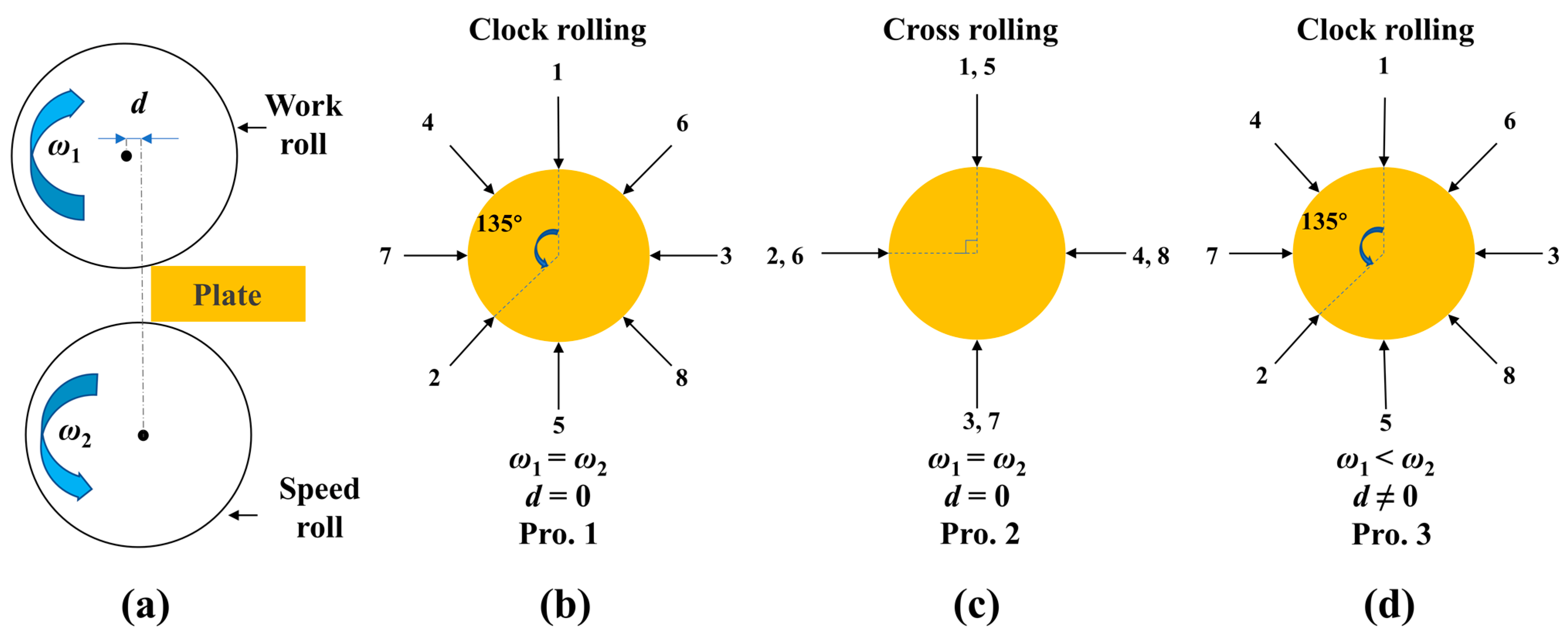
2.1. Determination of the Simulation Proposal and Corresponding Parameters

Figure 1a shows the front view of the rolling processes, illustrating the relationship between the plate and two rolls (upper and lower rolls, i.e., work and speed rolls). Three projects involve clock-synchronous rolling, cross-synchronous rolling, and clock–snake rolling, respectively referred to as Project 1 (Pro. 1), Project 2 (Pro. 2), and Project 3 (Pro. 3) (Figure 1b–d). The clock or cross rolling is achieved by changing the rolling direction by 135° or 90°, respectively. In combination with the rolling parameters shown in Table 1, it becomes evident that a rolling route difference is generated between Pros. 1 and 2, as well as a rolling method between Pros. 1 and 3. These differences can be utilized to investigate the variation patterns in the MFV, ESD, GSD, damage, and RF under the different projects.
Normally, the main parameters of rolling processes should be taken into consideration, including the rolling speed of the roll, the speed ratio between the work roll and speed roll, the rolling method, temperature, the number of rolling passes, and the reduction corresponding to the deformation amount per pass, as shown in Table 1 and Figure 1 and Figure 2. The rolling speed originates from manufacturers, which aligns with similar studies [27]. The confirmation of the speed is influenced by a multitude of factors, including contact friction, pressing force, and the physical properties of the material, to name a few [28]. The speed ratio of the work roll to the speed roll is set at 1:2 based on research results. It is corroborated that rolling the plate at a speed ratio of 1:2 can result in a greater effective strain compared with 1:1, which consequently yields a positive impact on further deformation [10,29].
As seen in Figure 2, identical parameters are adopted in three rolling projects including rolling temperature, thickness reduction, and the number of passes. The basic parameters in Figure 2, Table 1 and Table 2 are established based on the symmetric Al target rolling process from the manufacturer.
The configurations of reduction, rolling passes, and temperature settings often necessitate a comprehensive consideration based on dynamic recrystallization and ultimate requirements, such as refined grains and defect-free conditions. As shown in Figure 2, the primary purpose of the former three passes of rolling at 180 °C is material softening and thickness reduction. Below the temperature of dynamic recrystallization (0.4Tm, where Tm represents the melting point of aluminum), grains can be effectively fractured with increasing dislocation density [30,31]. This temperature also makes it conducive to the smooth bite of the rolling mill. When the plate becomes thinner after multi-pass rolling, the hardness will be too high to satisfy the bite condition if the temperature is set too low. On the contrary, if the temperature is set to high, heat deformation will occur after multiple roll passes and give rise to bonding between the material surface and the roll. This could produce defects such as pits and cracks on the surface, which would further affect the grain size. Furthermore, the appropriate temperature setting is of benefit in controlling production costs. The temperature for the remaining passes is set by 320 °C above 0.4Tm to obtain refined grains when dynamic recrystallization occurs.
Additionally, thickness reduction is another important parameter. Although a higher thickness reduction per pass (TRPP) can significantly improve productivity, it is important to note that cumulative reduction amplifies the deformation amount. This reaches 50% at pass 4, thereby storing energy for dynamic recrystallization [32]. This process results in grain refinement, as demonstrated by studies indicating that significant dynamic recrystallization occurs when deformation reaches 50% [33]. With an increase in rolling passes, continuous dynamic recrystallization yields an ultra-fine grain structure [34], which is anticipated and desired. Nonetheless, an excessive TRPP can lead to serious defects such as cracking and alligatoring [35]. Therefore, it can be easily inferred that the combination design of softening temperature and deformation amount would yield the dual benefit of reducing defects and improving grain refinement and homogenization.
The related physical parameters of pure aluminum and rollers in this work are shown in Table 3. The roller is configured as a rigid body in the simulation because of its overwhelmingly larger Young’s modulus than pure aluminum. Additionally, the presentation of physical parameters for 6061 aluminum alloy indicates its high similarity to pure aluminum, thus enabling the recrystallization kinetics model obtained from 6061 aluminum alloy to be utilized for approximating the microstructure evolution process of pure aluminum targets, as detailed below [2].

2.2. Establishment of Geometric Models and Numerical Models

The geometrical models, including the pure Al plate and rolls, are constructed using Creo Parametric 2.0 and then imported into DEFORM 3D 10.2 with the ‘.STL’ format for meshing and subsequent calculation. Table 2 reveals that the initial size, the final thickness requirement, and the average value of the initial grain size are provided by the funding company (see the Acknowledgements Section). To satisfy the biting conditions during rolling, we set the same diameter for the work and speed roll at 800 mm based on practical production lines as well.
The boundary conditions in this paper include friction and heat conduction on all contact surfaces. Roll deformation and heat dissipation, which are process controllable factors, are negligible as the primary focus of this paper is to investigate the influence of the rolling route and methods on the MFV, ESD, GSD, damage, and RF results.
As presented in Table 4, coefficients of friction and convection heat transfer between the work roll and workpiece are set to 0.5 and 25 N·s−1mm−1·°C−1, respectively, regardless of synchronous or asynchronous rolling. The heat transfer coefficient is a crucial parameter for predicting the temperature of rolled materials during the hot rolling process. Under dry friction conditions, the heat exchange coefficient between aluminum and steel ranges from 7 to 34 N·s−1mm−1·°C−1 [36]. Moreover, the environmental temperature is kept at the same value as that of workpiece in all passes. This implies that there is no heat exchange among the workpiece, roll, and environment under the various projects in order to eliminate heat transfer. For the friction coefficient setting, a shear friction model is employed under non-lubricated rolling conditions. Given the increased friction force resulting from material surface oxidation or softening at high temperature, it is rational to set the nondimensional friction coefficient at 0.5 [37]. To sum up, these projects are realized only by changing the temperature field to achieve the impact of rolling routes and methods on the MFV, ESD, GSD, RF, microstructure evolution, etc., leaving out controllable and harmful factors.
The numerical models of pure Al, including stress–strain models, ductile fracture models, and dynamic recrystallisation models, were built in DEFORM 3D software. The former two models that exist in the materials library were adopted to study the plastic deformation of purity aluminum by N. Haghdadi et al. [38], whose results demonstrated a close correlation between the simulation and the experiment.
Firstly, the stress–strain model should be established based on the true stress–strain curve, and its functional relationship is as follows:
σ = σ ε , ε , ˙ T
where σ is the stress; ε is the strain; ε ˙ is the strain rate; and T is the temperature.
Secondly, the rolling procedure of metallic materials causes substantial plastic deformation, necessitating taking the ductile fracture model into consideration in the simulation. Typically, these models encompass the Normalized Cockcroft and Latham (C&L) rule, Brozzo rule, and Oyane rule [39,40]. Cockcroft and Latham contended that, from a microscopic perspective, crack initiation is closely related to the stress–strain history during the deformation of metallic materials. The primary driving force behind the continuous accumulation of tensile stress–strain energy is the principal tensile stress, where the tensile stress–strain energy can be defined as the fracture damage factor (C), expressed as [35,41]:
C = 0 ε ¯ f σ * σ ¯ d ε ¯
where damage factor C is a dimensionless ratio value; σ ¯ is the true effective stress; ε ¯ is the true effective strain; ε ¯ f is the effective strain when a fracture occurs; and σ * is the maximum principal stress. According to the relationship between the rolling process and its initiating factors of cracks, the C&L rule is adopted in this work.
Finally, given the similarities in physical properties between pure aluminum and 6061 aluminum alloy, this study establishes a dynamic recrystallization model drawing on the relevant literature, as list in Table 3 [2]. Specifically, the dynamic recrystallization model can be represented as the Avrami equation format [42] shown in Table 5.

3. Results and Discussion

To facilitate the analysis of the simulation results, we established 23 tracking points in the longitudinal center section perpendicular to the rolling direction, including the surface points, point 1 and point 23, located close to the work roll and speed roll, respectively, as illustrated in Figure 3. The variables of the MFV, damage, ESD, GSD, and RF in the longitudinal section and the evolving trend in the thickness direction were analyzed to study the effects of different rolling routes and methods on them. For this purpose, several representative rolling passes, including the first, fourth, sixth, and eighth passes, under different projects were selected for analysis and discussion.

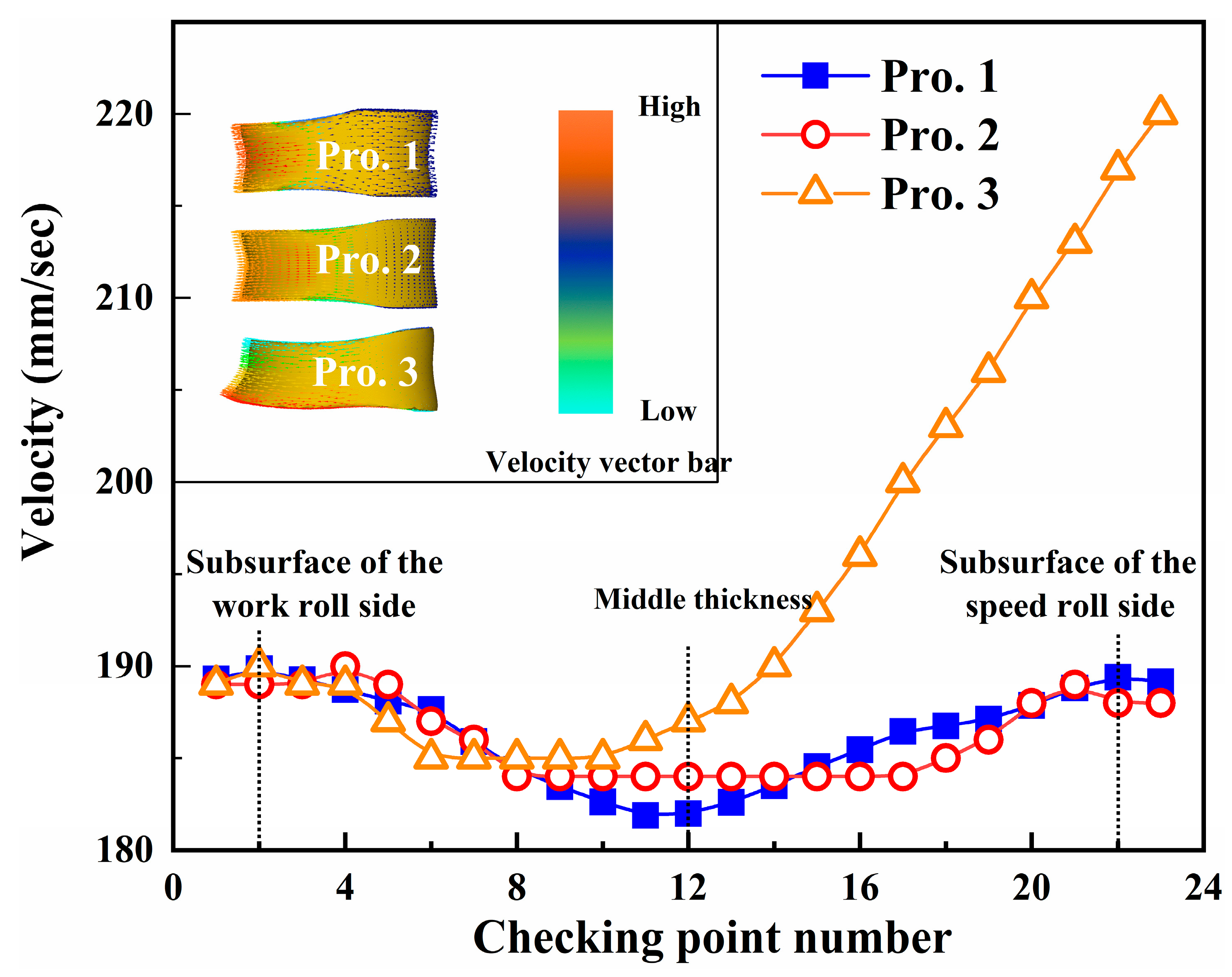
3.1. Comparison of MFV among the Three Projects

Figure 4 displays the flow velocity distribution in the height direction of the plate for all three rolling projects in representative pass 5. As a result of synchronous rolling, the distribution and value of MFV in Pros. 1 and 2 with different rolling routes are nearly symmetrical and identical, forming an ‘M’ shape. This demonstrates that the change in the rolling route has a minimal effect on the MFV, whereas the flow velocity of the subsurface is slightly higher than that of the surface. Point 11, with the lowest value, is nearly located at the center, as denoted by a dotted line and referred to as the middle thickness (see Figure 4). This suggests that friction between the roll and plate impedes the metal flow on the surface. However, it is worth noting that the MFV in snake rolling (Pro. 3, which is asynchronous rolling) exhibits a rapid increase with depth from the center (middle thickness) to the subsurface of the speed roll in contrast to Pro. 1. The MFV increment and point 23 in Pro. 3 are ~2% and 15.8%, respectively, compared with Pros. 1 and 2 (synchronous rolling). However, the velocity values near the subsurface of the work roll in Pro. 3 are almost identical to those in Pros. 1 and 2, as seen on the left side of the dotted line in Figure 4. The higher minimum of the MFV obtained at point 6 in Pro. 3 is closer to the velocity value at the surface of the work roll, unlike the center position in Pros. 1 and 2. Some studies suggest that the metal in the lower layer of the plate flows more rapidly when using the snake rolling method, resulting in larger effective strain and heterogeneous strain distribution in the thickness direction [43,44]. The difference in flow velocity along the thickness direction under the three projects can be visually observed in the inset of Figure 4, which presents the vector of the MFV. Therefore, it is meaningful to discuss the effect of different rolling projects on ESD.

3.2. Comparison of ESD among the Three Projects

Figure 5 shows the ESD in the longitudinal section of the plate under the different projects. It is noticeable that uneven deformation is generated in the plate under different projects, in particular, the ESD before the sixth pass appears as an X-shaped distribution. The effective strain on the surface is the largest, while the smaller strain is in the center, which is similar to the flow velocity distribution shown in Figure 4. The uneven deformation is related to the geometric shape factor S = l / h a v e , where l is the contact length between the rolls and workpiece and h a v e = ( H + h ) / 2 represents the mean thickness of the sample before and after deformation, i.e., the average value of H and h [45]. S increases with increasing rolling passes, resulting in a smaller adhesion zone and a larger sliding zone. Extremely homogeneous deformation forms when the plate is thick with a low S value. The deformation is not substantial enough to penetrate the entire height of the section, which should be the reason for the X-shaped ESD. But when the plate becomes thin enough after multi-pass rolling, S reaches a certain value, leading to a full sliding area without an adhesion zone. Consequently, the deformation becomes more uniform and can penetrate into the entire longitudinal section. This situation can be observed for the plate in the eighth pass for all three projects, as shown in Figure 5d,h,l.
Figure 5a,e,i show the ESDs of the first pass for the three projects, which are almost identical, with a value range of 0.0729–0.295. In the fourth and sixth passes, the ESDs for Pro. 1 and Pro. 2, with the differences in the rolling route, are symmetrically distributed, ranging from 0.752 to 1.3 and 1.8 to 2.38, respectively, as seen in Figure 5b,c,f,g. Moreover, the ESD increases firstly from the surface to the subsurface and then decreases further to the center of the longitudinal section. But in the eighth pass, the ESD of clock rolling (Pro. 1) is more even, ranging from 3.32 to 4.32, in contrast to cross rolling (Pro. 2), where the maximum value of the effective strain is 6.3. This indicates that the rolling route hardly changes the ESD when S is large, but S would decrease greatly and further affect the ESD in the clock rolling process. This may lead to a smaller maximum value of effective strain and more uniform ESD in clock rolling than those in the cross rolling process.
Unlike synchronous rolling (Pros. 1 and 2), the values of effective strain gradually increase in the asynchronous rolling process, specifically in clock–snake rolling (Pro. 3), along the thickness direction from the work roll side to the speed roll side with a small enough S, as shown in Figure 5j–l. Notably, the effective strain at the speed roll side is obviously higher than that at the work roll side, which benefits from the combined influence of the speed ratio and offset distance. The minimum effective strain exists at a position closer to the surface of the work roll, unlike the center position in Pros. 1 and 2, indicating that the effective strain of asynchronous rolling is deeper into the material than that of synchronous rolling. This is also the reason why the minimum flow velocity in Pro. 3 (Figure 4) is not at the center. These two characteristics of the ESD are consistent with the distribution of flow velocity. This suggests that rolling increases the effective strain and flow rate compared with synchronous rolling.
As the rolling pass number continues to increase, the ESD can span the entire cross-section. As shown in Figure 5d,h,l, the maximum values of the ESD in the inner plate are 4.3, 5.8, and 5.8 for Pros. 1, 2, and 3, respectively. Considering the consistency in the effective strain reflected by the distribution of the color area, clock rolling results in a more uniform ESD with a larger maximum value of effective strain in contrast to cross rolling, but clock rolling may exhibit a more uniform GSD (see the next section). This is because continuous and normal grain growth types are predominant during the clock rolling process, as well as randomly oriented grain regions filled with high-angle grain boundaries that are characterized by high mobility [25]. Furthermore, asynchronous rolling can improve the maximum value of effective strain compared with synchronous rolling because of a deeper effective strain into the plate with the combined effects of the offset distance and speed ratio [44,46].
Based on these results, clock rolling can make the ESD more uniform, and a deeper penetration of ESD can be achieved in asynchronous rolling. It has been reported that the larger the effective strain, the greater the storage energy generated during plastic deformation, which provides the driving power for recrystallization with smaller grains [47,48]. Accordingly, we analyzed the relationship between the final ESD and GSD under the different projects.

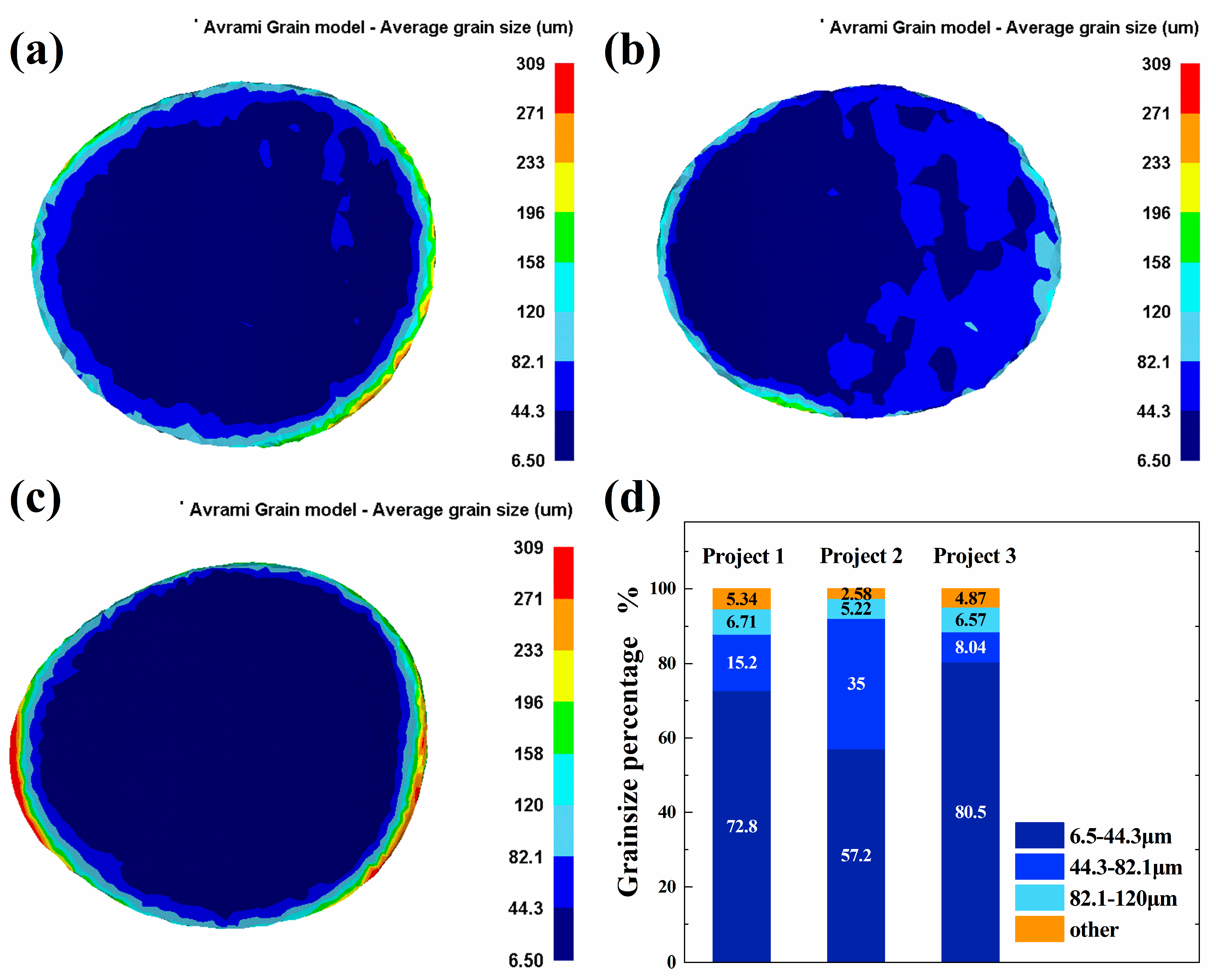
3.3. Comparison of GSD among the Three Projects

Figure 6 shows the simulated results of GSD under Pros. 1 (Figure 6a), 2 (Figure 6b), and 3 (Figure 6c). It is found that the final average grain size mainly concentrates on the scope between 6.5 and 82 μm, as reflected by the distribution of the colored area. Grain sizes larger than 82 μm are distributed along the edge of the plate for the three projects presented in Figure 6a–c. Combined with the proportion of the top-three grain sizes for each project exhibited in Figure 6d, the smallest size range, 6.5–44.3 μm, denoted by deep blue, accounts for the largest proportion for Projects 1, 2, and 3, being 72.8%, 57.2%, and 80.5%, respectively. Consequently, the final grain sizes of the three projects compared with the initial one of 520 μm demonstrate that dynamic recrystallization would occur under the conditions of 90% cumulative deformation and the rolling temperature of 320 °C, which facilitate recrystallization of the pure Al target.
It is necessary to analyze the effect of different rolling methods and routes on GSD under the various projects. The proportions of the second-ranked grain size, 44.3–82.1 μm, in Pros. 1 and 2 with different rolling routes reach 15.2% and 35%, respectively (Figure 6a,b,d). This demonstrates that the clock rolling method yields a more uniform GSD and a larger percentage of the smallest size grains than cross rolling. This advantage stems from the larger and more uniform ESD achieved in clock rolling, as previously discussed (Figure 5d,h). Consequently, grains with easier growth and a more homogeneous microstructure are achieved [25]. Under the different rolling methods, note that the smallest grain size ranges observed in Pros. 1 and 3 account for 72.8% and 80.5%, respectively, which suggests that the asynchronous rolling strategy can produce finer grains compared with the symmetrical rolling route, as shown in Figure 6a,c,d. This is conducive to a larger effective strain on the speed roll side and the additional cross-shear strain (Figure 5d,l), which arises from the combined effects of the offset distance and speed ratio [49].
It should be emphasized that excellent sputtered film quality requires excellent metal targets with not only a small and uniform GSD but also defect-free conditions. As a result, the trends in the distribution of damage values should be studied and discussed.

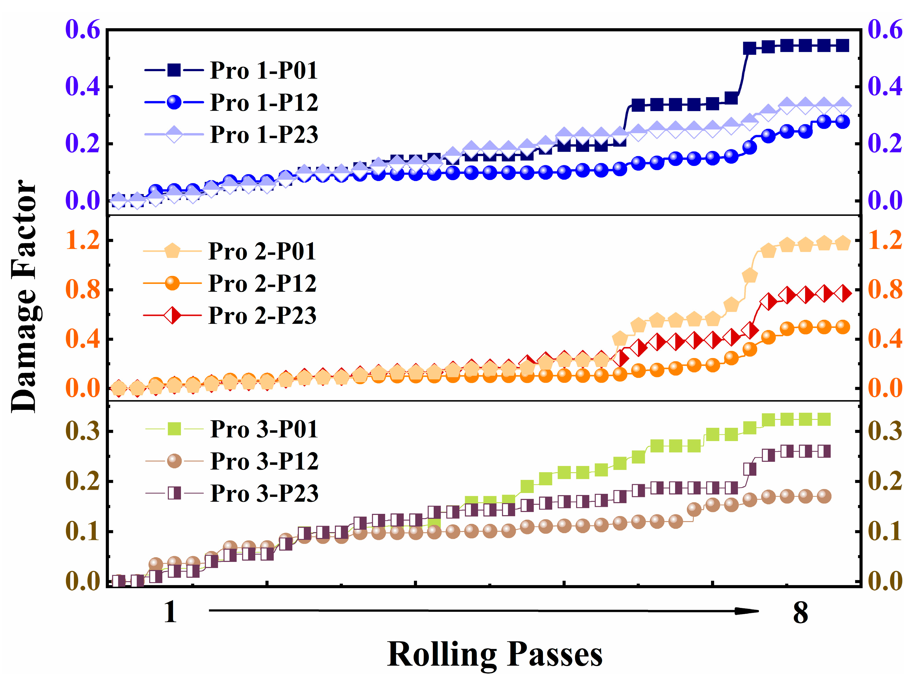
3.4. Comparison of Damage among the Three Projects

Figure 7 shows the distribution of damage in the cross-section for all projects. The corresponding values under all passes exhibit a symmetrical distribution, with the maximum at the edges, gradually tapering off toward the center of the plate. This is attributed to the influence of stress on the corners of the roll plate during the rolling process. Furthermore, the severity of stress concentration corresponds to higher damage values, posing a higher risk of cracking at the corners [50]. As shown in Figure 7j,k (Pro. 3), a convex exists at the corner of the speed roll side accompanied by the highest damage values because of the increased effective strain and higher MFV of the speed roll side in asynchronous rolling (Figure 4 and Figure 5j,k). Similarly, it can be inferred that in Pros. 1 and 2, as shown in Figure 7b,c,f,g, a concave forms in the middle thickness owing to the synchronous ESD and MFV in synchronous rolling (Figure 4 and Figure 5b,c,f,j), which proves that the damage factor increases on the edge of the plate, associated with alterations in the morphology of the zone [41].
From the distribution of the damage factor, it is observed that the edges of the plate are more susceptible to defects. However, these can be corrected and removed in an additional process, considering the assurance of an effective utilized area. Hence, more focus should be placed on the center of the plate rather than its edges. On the other hand, it is evident that the distribution of damage for the plate treated under Pro. 1 is more uniform and possesses a smaller damage factor compared with Pro. 2, as shown in Figure 7d, h. This implies that the clock-rolled plate exhibits a relatively lower risk of forming defects compared with the cross-rolled plate. In addition, note that the maximum damage factors are 0.442, 0.635, and 0.249 for Pros. 1, 2, and 3, respectively, (see Figure 7d, h, l, excluding the damage factors of the edge in the three projects, i.e., larger than 0.828). This suggests that the defect risk under Pro. 3 is substantially reduced because of the combined impact of both the offset distance and speed ratio. Thus, clock–snake rolling has the lowest defect risk, while cross-synchronous rolling has the highest risk.
To substantiate the argument above, tracking points at Points 1, 12, and 23 (see Figure 3), representing the upper, core, and lower surfaces of the plate, are chosen from the different projects to examine the damage variation during eight rolling passes. As presented in Figure 8, the damage factor at all three points increases with the increasing number of rolling passes. In the final state, the maximum damage factors under Pros. 1, 2, and 3 are 0.5, 1.2, and 0.3, respectively, displayed by curves Pro1-01, Pro2-01, and Pro3-P01. The results demonstrate that clock rolling and asynchronous rolling can reduce the maximum damage factor by 58% and 36% compared with cross rolling and synchronous rolling, respectively. Contrastingly, clock–snake rolling (Pro. 3) can diminish the defect risk by 73% compared with cross-synchronous rolling (Pro. 2).
The magnitude of the damage factor for materials is heavily influenced by the RF. The higher the RF value, the greater the likelihood of forming defects. Consequently, it is important to calculate and discuss the trend in the RF under different projects.

3.5. Comparison of RF among the Three Projects

Figure 9 shows the rolling pass dependence of the RF under three different rolling projects. The inserted table in Figure 9 shows the specific RF values corresponding to the points extracted from the three curves. For the complete rolling process, we observed that the RF increases at the beginning of the rolling process, reaching a maximum and then starting to decline followed by a plateau. After eight passes, it is evident that eight parabolic-like peaks signify the completion of eight rolling passes. Notably, the maximum RF value exhibits an increasing trend with the rolling passes. Meanwhile, the RF curves are identical for the three projects before the fifth pass. From the sixth pass onward, the RF maximum for all projects starts to exhibit an evident difference. It is particularly interesting that significant disparities in the peak value of the RF are observed from the seventh pass to the eighth pass for all three projects (Figure 9). Furthermore, it should be noted that the RF difference between the seventh and eighth passes is largest for Pro. 1, followed by Pro. 2, and is the smallest for Pro. 3. In stark contrast to Pro. 2, the maximum RF in the 7seventh pass decreases by 13% for Pro. 1 and 38% for Pro. 3. Similarly, the maximum RF decreases by 33% for Pro. 1 and 51% for Pro. 3 in the eighth pass. It is evident that the maximum RF could be reduced by 33% and 22% during the clock rolling and asynchronous rolling processes, respectively, compared with cross rolling and synchronous rolling. This suggests that in terms of energy balance or equilibrium stress analysis, rolling-speed-mismatching in asynchronous rolling provides a component of the total energy, known as cross shearing, to generate frictional power [51].
Based on Figure 6 and Figure 9, the snake–clock rolling process guarantees a more consistent grain size. Simultaneously, reducing the RF effectively decreases the damage value of the rolled parts. Consequently, this minimizes the risk of defect formation and substantially reduces production energy waste. It appears that altering the direction or method of rolling has minimal impact on the RF when the thickness of the plate is substantial. As the number of rolling passes increases, so does the RF, resulting in a decrease in plate thickness. Based on Figure 6 and Figure 7, clock–snake rolling yields a lower RF and damage factor compared with cross-synchronous rolling under the same rolling method. While changing the rolling method based on the clock rolling route, the RF decreases in the clock–snake rolling process, achieving greater grain size uniformity compared with clock-synchronous rolling. Thus, the risk of defects is effectively brought down. Moreover, the metal flow and ESD on the speed roll side are enhanced owing to the presence of the aforementioned frictional power. Consequently, less power is supplied by the RF [51], resulting in a significant reduction in production energy consumption. In summary, the simulation results indicate that Pro. 3 exhibits greater deformation compared with the others, and it enhances the MFV and ESD. Combined with the structural uniformity promoted by the clock rolling path, a more uniform GSD is achieved. Additionally, the lowest damage factor is obtained because of the small rolling force involved, as compared with synchronous rolling.

4. Conclusions

In this study, we developed three distinct finite element models utilizing DEFORM 3D 10.2 software to investigate the effects of various rolling routes and methods on the mean force vector (MFV), damage, electrostatic spraying (ESD), grain size distribution (GSD), and rolling force (RF) during the fabrication of high-purity Al targets. The rolling routes examined included clock-synchronous, cross-synchronous, and clock–snake rolling.
The key findings include the following:
  • Clock rolling route: Compared with cross rolling, the clock rolling route promotes grain size homogeneity (GSD) because of randomly oriented grain regions filled with high-angle grain boundaries.
  • Asynchronous rolling method: The MFV and effective strain increase during asynchronous rolling because of deeper deformation, resulting in grain refinement and a grain size range of 6.5 to 44.3 μm in clock–snake rolling (Pro. 3), accounting for ~80.5% of all grains.
  • Reduced RF consumption: As the RF is utilized to form cross-shearing stress as component energy in asynchronous rolling, the maximum RF decrement reaches 51%, significantly reducing the risk of defects and improving energy efficiency.
These simulation results hold great significance for guiding practical production in the metal target industry. The stress flow testing of pure aluminum targets is of great significance. However, it is essential to characterize microstructure homogeneity using Electron Backscatter Diffraction (EBSD) to obtain the grain orientation. The establishment of tests can help calibrate dynamic recrystallization models, thus enhancing the precision of microstructure evolution simulations.

Author Contributions

Conceptualization, investigation, writing—review and editing, and funding acquisition, S.M. Methodology, software, and writing—original draft preparation, C.Q. Investigation, software, and data curation, R.X. and X.X. All authors have read and agreed to the published version of the manuscript.

Funding

This work was financially supported by the Major Science and Technology Research and Development Special Funds Project of Jiangxi Province (Grant No. 20194ABC28005) and the National Natural Science Foundation of China (Grant No. 52061014).

Data Availability Statement

The datasets presented in this article are not readily available due to technical limitations. Requests to access the datasets should be directed to the corresponding author of the article, who can be reached at [email protected]. Please include a brief description of your research interests and how accessing the datasets would benefit your research. The authors will consider each request on a case-by-case basis and may provide access under certain conditions, such as signing a data use agreement and ensuring the confidentiality of the information.

Acknowledgments

We are grateful to Changcai Chen, Xiaohua Luo, and Chunsheng Fang from the School of Materials Science and Engineering, Faculty of Materials Metallurgy and Chemistry, Jiangxi University of Science and Technology, Ganzhou, for their valuable guidance, support, and assistance throughout this project. Their expertise and knowledge contributed greatly to the success of this research. Additionally, I would like to express my sincere gratitude to Yongwen Yuan, from Raenin Materials Co., Ltd., Ganzhou 341000, People’s Republic of China, for his constructive comments and suggestions on the Al rolling process in this work. His inputs significantly improved the quality of thus paper.

Conflicts of Interest

The authors declare no conflicts of interest.

References

  1. Gamin, Y.V.; Akopyan, T.K.; Koshmin, A.N.; Dolbachev, A.P.; Goncharuk, A.V. Microstructure evolution and property analysis of commercial pure Al alloy processed by radial-shear rolling. Arch. Civ. Mech. Eng. 2020, 20, 143. [Google Scholar] [CrossRef]
  2. Yu, Z.-M.; Peng, W.-F.; Zhang, X.; Oleksandr, M.; Titov, V. Evolution of microstructure of aluminum alloy hollow shaft in cross wedge rolling without mandrel. J. Cent. South Univ. 2022, 29, 807–820. [Google Scholar] [CrossRef]
  3. Daneshmand, S.; Sajadi, S.M.; Vini, M.H. A molecular dynamics simulation on corrosion, wear, and mechanical properties of laminated Al/TiC composites. Eng. Anal. Bound. Elem. 2023, 152, 598–607. [Google Scholar] [CrossRef]
  4. Jiang, L.-Y.; Zhen, T.; Huang, J.-B.; Wei, Y.-Y.; Li, H.; Ma, L.-F. Calculation and analysis of rolling force during aluminum alloy thick plate snake/gradient temperature rolling with different roll diameters. Int. J. Adv. Manuf. Technol. 2021, 115, 3453–3465. [Google Scholar] [CrossRef]
  5. Zhang, T.; Wu, Y.; Gong, H.; Shi, W.; Jiang, F.; Jiang, S. Analysis of temperature asymmetry of aluminum alloy thick plate during snake hot rolling. Int. J. Adv. Manuf. Technol. 2016, 87, 941–948. [Google Scholar] [CrossRef]
  6. Jiang, L.-Y.; Zhao, C.-J.; Yuan, G.; Shi, J.-H.; Wang, G.-D. Thicker steel plate shape-changing law and control method during the snake rolling process. Metall. Res. Technol. 2016, 113, 309. [Google Scholar] [CrossRef]
  7. Wang, X.; Zhang, W.; Ai, Y.; Trzepieciński, T. Prediction of Exit Thickness and Its Compensation after Snake Rolling of Aluminum Alloy Thick Plate. Adv. Mater. Sci. Eng. 2022, 2022, 9815523. [Google Scholar] [CrossRef]
  8. Zhang, T.; Wu, Y.-X.; Gong, H.; Zheng, X.-Z.; Jiang, S.-S. Effects of rolling parameters of snake hot rolling on strain distribution of aluminum alloy 7075. Trans. Nonferrous Met. Soc. China 2014, 24, 2150–2156. [Google Scholar] [CrossRef]
  9. Yang, J.; Li, S.; Liu, J.; Li, X.; Zhang, X. Finite element analysis of bending behavior and strain heterogeneity in snake rolling of AA7050 plates using a hyperbolic sine-type constitutive law. J. Mater. Process. Technol. 2017, 240, 274–283. [Google Scholar] [CrossRef]
  10. Hao, P.; Liu, J. Influence of snake rolling on metal flow in hot rolling of aluminum alloy thick plate. Mech. Ind. 2020, 21, 525. [Google Scholar] [CrossRef]
  11. Luo, D.; Pan, Y.; Wang, H.Y.; Zhao, L.G.; Liu, G.J.; Liu, Y.; Jiang, Q.C. Effect of Rolling Route on Microstructure and Tensile Properties of Twin-Roll Casting AZ31 Mg Alloy Sheets. Materials 2016, 9, 433. [Google Scholar] [CrossRef]
  12. Vincze, G.; Butuc, M.C.; Barlat, F.; Lopes, A.B.; Silva, T.F.V. Strain path changes in aluminum. In Proceedings of the 22nd International Esaform Conference on Material Forming, Vitoria-Gasteiz, Spain, 8–10 May 2019. [Google Scholar]
  13. Dhinwal, S.S.; Toth, L.S. Unlocking Deformation Path in Asymmetric Rolling by Texture Simulation. Materials 2019, 13, 101. [Google Scholar] [CrossRef] [PubMed]
  14. Xu, J.; Peng, Y.; Guan, B.; Xin, Y.; Chapuis, A.; Huang, G.; Liu, Q. Tailoring the microstructure and texture of a dual-phase Mg–8Li alloy by varying the rolling path. Mater. Sci. Eng. A 2022, 844, 143202. [Google Scholar] [CrossRef]
  15. Deng, C.; Liu, S.F.; Ji, J.L.; Hao, X.B.; Zhang, Z.Q.; Liu, Q. Texture evolution of high purity tantalum under different rolling paths. J. Mater. Process. Technol. 2014, 214, 462–469. [Google Scholar] [CrossRef]
  16. Zhu, J.; Liu, S.; Yuan, X.; Liu, Q. Comparing the Through-Thickness Gradient of the Deformed and Recrystallized Microstructure in Tantalum with Unidirectional and Clock Rolling. Materials 2019, 12, 169. [Google Scholar] [CrossRef]
  17. Yang, Y.; Wang, J.-L.; Chen, Y.-D.; Hu, H.-B. Effect of strain rate on microstructural evolution and thermal stability of 1050 commercial pure aluminum. Trans. Nonferrous Met. Soc. China 2018, 28, 1–8. [Google Scholar] [CrossRef]
  18. Oertel, C.G.; Hünsche, I.; Skrotzki, W.; Lorich, A.; Knabl, W.; Resch, J.; Trenkwalder, T. Influence of cross rolling and heat treatment on texture and forming properties of molybdenum sheets. Int. J. Refract. Met. Hard Mater. 2010, 28, 722–727. [Google Scholar] [CrossRef]
  19. Wronski, S.; Wrobel, M.; Baczmanski, A.; Wierzbanowski, K. Effects of cross-rolling on residual stress, texture and plastic anisotropy in f.c.c. and b.c.c. metals. Mater. Charact. 2013, 77, 116–126. [Google Scholar] [CrossRef]
  20. Aditya, A.V.; Subramanian, P.K.; Gopala Krishna, V.; Chinta Babu, U. Influence of Rolling Path on Microstructure and Mechanical Properties in EB Refined Tantalum. Trans. Indian Inst. Met. 2012, 65, 435–442. [Google Scholar] [CrossRef]
  21. Zhang, X.; Yan, Q.; Lang, S.; Wang, Y.; Ge, C. Preparation of pure tungsten via various rolling methods and their influence on macro-texture and mechanical properties. Mater. Des. 2017, 126, 1–11. [Google Scholar] [CrossRef]
  22. Fan, H.; Liu, S.; Li, L.; Deng, C.; Liu, Q. Largely alleviating the orientation dependence by sequentially changing strain paths. Mater. Des. 2016, 97, 464–472. [Google Scholar] [CrossRef]
  23. Zhu, J.; Liu, S.; Yang, S.; Long, D.; Liu, Y.; Yuan, X.; Orlov, D. Strain dependence of deformation and recrystallization microstructure homogeneity in clock-rolled tantalum sheets. Mater. Charact. 2020, 161, 110165. [Google Scholar] [CrossRef]
  24. Liu, S.-F.; Hao, X.-B.; Deng, C.; Fan, H.-Y.; Liu, Q. Revealing substructure in clock-rolled Ta aided with triple focused ion beam. Rare Met. 2015, 36, 284–288. [Google Scholar] [CrossRef]
  25. Kim, H.-C.; Kang, C.-G.; Huh, M.-Y.; Engler, O. Effect of primary recrystallization texture on abnormal grain growth in an aluminum alloy. Scr. Mater. 2007, 57, 325–327. [Google Scholar] [CrossRef]
  26. Gurao, N.P.; Sethuraman, S.; Suwas, S. Effect of strain path change on the evolution of texture and microstructure during rolling of copper and nickel. Mater. Sci. Eng. A 2011, 528, 7739–7750. [Google Scholar] [CrossRef]
  27. Konstantinov, I.L.; Baranov, V.N.; Sidelnikov, S.B.; Arnautov, A.D.; Voroshilov, D.S.; Dovzenko, N.N.; Zenkin, E.Y.; Bezrukikh, A.I.; Dovzenko, I.N.; Yuryev, P.O. Investigation of cold rolling modes of 1580 alloy by the method of computer simulation. Int. J. Adv. Manuf. Technol. 2021, 112, 1965–1972. [Google Scholar] [CrossRef]
  28. Hum, B.; Colquhoun, H.W.; Lenard, J.G. Measurements of friction during hot rolling of aluminum strips. J. Mater. Process. Technol. 1996, 60, 331–338. [Google Scholar] [CrossRef]
  29. Zhang, T.; Li, L.; Lu, S.-H.; Zhang, J.-B.; Gong, H. Comparisons of flow behavior characteristics and microstructure between asymmetrical shear rolling and symmetrical rolling by macro/micro coupling simulation. J. Comput. Sci. 2018, 29, 142–152. [Google Scholar] [CrossRef]
  30. Liu, F.; Yuan, H.; Yin, J.; Wang, J.T. Influence of stacking fault energy and temperature on microstructures and mechanical properties of fcc pure metals processed by equal-channel angular pressing. Mater. Sci. Eng. A 2016, 662, 578–587. [Google Scholar] [CrossRef]
  31. Zhang, L.; Wang, Y.; Ni, S.; Chen, G.; Li, K.; Du, Y.; Song, M. The Evolution of Second-Phase Particles in 6111 Aluminum Alloy Processed by Hot and Cold Rolling. J. Mater. Eng. Perform. 2018, 27, 1130–1137. [Google Scholar] [CrossRef]
  32. Yim, C.D.; Seo, Y.M.; You, B.S. Effect of the reduction ratio per pass on the microstructure of a hot-rolled AZ31 magnesium alloy sheet. Met. Mater. Int. 2009, 15, 683–688. [Google Scholar] [CrossRef]
  33. Bagheripoor, M.; Bisadi, H. Effects of rolling parameters on temperature distribution in the hot rolling of aluminum strips. Appl. Therm. Eng. 2011, 31, 1556–1565. [Google Scholar] [CrossRef]
  34. Lienshöft, L.; Chekhonin, P.; Zöllner, D.; Scharnweber, J.; Marr, T.; Krauter, T.; Hoeppel, H.W.; Skrotzki, W. Static recrystallization and grain growth of accumulative roll bonded aluminum laminates. J. Mater. Res. 2017, 32, 4503–4513. [Google Scholar] [CrossRef]
  35. Saanouni, K. On the numerical prediction of the ductile fracture in metal forming. Eng. Fract. Mech. 2008, 75, 3545–3559. [Google Scholar] [CrossRef]
  36. Olaogun, O.; Edberg, J.; Lindgren, L.E.; Oluwole, O.O.; Akinlabi, E.T. Heat transfer in cold rolling process of AA8015 alloy: A case study of 2-D FE simulation of coupled thermo-mechanical modeling. Int. J. Adv. Manuf. Technol. 2018, 100, 2617–2627. [Google Scholar] [CrossRef]
  37. Liu, Y.; Zhu, Z.; Wang, Z.; Zhu, B.; Wang, Y.; Zhang, Y. Flow and friction behaviors of 6061 aluminum alloy at elevated temperatures and hot stamping of a B-pillar. Int. J. Adv. Manuf. Technol. 2018, 96, 4063–4083. [Google Scholar] [CrossRef]
  38. Haghdadi, N.; Zarei-Hanzaki, A.; Abou-Ras, D.; Maghsoudi, M.H.; Ghorbani, A.; Kawasaki, M. An investigation into the homogeneity of microstructure, strain pattern and hardness of pure aluminum processed by accumulative back extrusion. Mater. Sci. Eng. A 2014, 595, 179–187. [Google Scholar] [CrossRef]
  39. Zhang, B.; Ning, S.; Wei, Z.; Duan, Y.; Li, X.; Yang, Y. Simulation and Experimental Study on Roll-Forming Limit of Cup. Materials 2022, 15, 1279. [Google Scholar] [CrossRef]
  40. Lanjewar, H.; Kestens, L.A.I.; Verleysen, P. Damage and strengthening mechanisms in severely deformed commercially pure aluminum: Experiments and modeling. Mater. Sci. Eng. A 2021, 800, 140224. [Google Scholar] [CrossRef]
  41. González-Castillo, A.C.; Cruz-Rivera, J.d.J.; Ramos-Azpeitia, M.O.; Garnica-González, P.; Garay-Reyes, C.G.; Pacheco-Cedeño, J.S.; Hernández-Rivera, J.L. 3D-FEM Simulation of Hot Rolling Process and Characterization of the Resultant Microstructure of a Light-Weight Mn Steel. Crystals 2021, 11, 569. [Google Scholar] [CrossRef]
  42. Li, K.; Pan, Q.; Li, R.; Liu, S.; Huang, Z.; He, X. Constitutive Modeling of the Hot Deformation Behavior in 6082 Aluminum Alloy. J. Mater. Eng. Perform. 2019, 28, 981–994. [Google Scholar] [CrossRef]
  43. Kim, W.J.; Lee, K.E.; Choi, S.H. Mechanical properties and microstructure of ultra fine-grained copper prepared by a high-speed-ratio differential speed rolling. Mater. Sci. Eng. A 2009, 506, 71–79. [Google Scholar] [CrossRef]
  44. Kim, W.J.; Yoo, S.J.; Jeong, H.T.; Kim, D.M.; Choe, B.H.; Lee, J.B. Effect of the speed ratio on grain refinement and texture development in pure Ti during differential speed rolling. Scr. Mater. 2011, 64, 49–52. [Google Scholar] [CrossRef]
  45. Byon, S.M.; Lee, J.H.; Lee, Y. A study to determine a distinct value of front end bending for a given shape factor in flat rolling. Proc. Inst. Mech. Eng. Part B J. Eng. Manuf. 2011, 225, 2302–2308. [Google Scholar] [CrossRef]
  46. Loorentz; Ko, Y.G. Effect of differential speed rolling strain on microstructure and mechanical properties of nanostructured 5052 Al alloy. J. Alloys Compd. 2014, 586, S205–S209. [Google Scholar] [CrossRef]
  47. Cui, Q.; Ohori, K. Grain refinement of high purity aluminium by asymmetric rolling. Mater. Sci. Technol. 2013, 16, 1095–1101. [Google Scholar] [CrossRef]
  48. Zuo, F.-Q.; Jiang, J.-H.; Shan, A.-D.; Fang, J.-M.; Zhang, X.-Y. Shear deformation and grain refinement in pure Al by asymmetric rolling. Trans. Nonferrous Met. Soc. China 2008, 18, 774–777. [Google Scholar] [CrossRef]
  49. Jiang, L.-Y.; Zhen, T.; Yuan, G.; Huang, J.-B.; Wei, Y.-Y.; Li, H.; Wang, P. The mechanical parameters modeling of heavy steel plate snake/gradient temperature rolling with the same roll diameters. Metall. Res. Technol. 2020, 117, 301. [Google Scholar] [CrossRef]
  50. Rajesh, K.V.D.; Buddi, T. Finite element analysis of chromium and nickel alloyed steel billets forged under warm forming process using Deform-3D. Adv. Mater. Process. Technol. 2021, 8, 1386–1394. [Google Scholar] [CrossRef]
  51. Wang, J.; Liu, X.; Sun, X. Study on the relationship between asymmetrical rolling deformation zone configuration and rolling parameters. Int. J. Mech. Sci. 2020, 187, 105905. [Google Scholar] [CrossRef]
Figure 1. Schematic diagrams of different projects with different rolling directions and methods. (a) Front view of the rolling process with the relationship between the plate and rolls. (b) Pro. 1, clock-synchronous rolling with the clock direction, in with rolling speed ω 1 = ω 2 and offset distance d = 0. (c) Pro. 2, cross-synchronous rolling with ω 1 = ω 2 and d = 0. (d) Pro. 3, clock–snake rolling with ω 1 < ω 2 , d ≠ 0. The numbers around the cylindrical plate represent the rolling sequence under different rolling projects (bd).
Metals 14 00845 g001
Figure 2. Different temperatures and accumulated deformation amounts with different thickness reductions in each rolling pass for the 3 projects. The number of abscissae represents the number of rolling passes.
Metals 14 00845 g002
Figure 3. Twenty-three tracking points in the longitudinal center section perpendicular to the feeding direction of rolling. The red arrows indicate the feeding direction and rolling force direction.
Metals 14 00845 g003
Figure 4. Velocity distribution in the thickness direction for all three projects in rolling pass 5.
Metals 14 00845 g004
Figure 5. ESD of the longitudinal section inside the sample in different passes under different projects. (ad) Pro. 1, (eh) Pro. 2, and (il) Pro. 3. The shape factor S is shown in the corresponding number of passes.
Metals 14 00845 g005
Figure 6. Final GSD after 8 passes under different rolling projects. (a) Pro. 1. (b) Pro. 2, and (c) Pro. 3. (d) The proportion of the smallest grain size, i.e., the top three, under the different projects.
Metals 14 00845 g006
Figure 7. Damage factor distribution of the vertical longitudinal section inside the sample in different passes under the different projects. (ad) Pro. 1, (eh) Pro. 2, and (il) Pro. 3.
Metals 14 00845 g007
Figure 8. Comparison of the damage factor tendency for 3 tracking points from the top, middle, and bottom of the plate under the different projects with rolling passes.
Metals 14 00845 g008
Figure 9. Variation in the RF with rolling passes under the different projects.
Metals 14 00845 g009
Table 1. Rolling parameters for the 3 rolling projects.
Rolling ParameterPro. 1Pro. 2Pro. 3
Upper work roll speed ( υ 1 )/(rad/s)0.5650.5650.4712
Lower speed roll speed ( υ 1 )/(rad/s)0.5650.5650.565
Speed ratio ( υ 1 / υ 2 )1:11:11:1.2
Offset distance/mm0020
Rolling methodSynchronous rollingSynchronous rollingAsymmetrical snake rolling
Rolling routeClockCrossClock
Table 2. Parameters of the geometric model.
ParameterValue
Initial target size (diameter × height)/mmφ150 × 150
Requirement of final thickness of target/mm~13
Diameter of the work roll/mmφ800
Initial target grain size/μm520
Table 3. Physical parameters of materials and rollers.
MaterialPure AluminumAluminum Alloy 6061 [2]Roller (AISI-H-26)
Density/(g·cm−3)2.72.77.76
Young’s modulus/MPa68,90068,900220,000
Poisson ratio0.330.30.27
Thermal expansion coefficient/K−12.2 × 10−52.3 × 10−51 × 10−5
Thermal conductivity/(W·m−1·K−1)180.195171.224.5
Heat capacity/(N·mm−2·K−1)2.432.4460
Table 4. Boundary condition.
Boundary Condition ParameterValue
Initial temperature/°C180
Conditional temperature/°Csame as the plate
Convection heat transfer coefficient between the work roll and workpiece/(N·s−1mm−1·°C−1)25
Friction coefficient between the work roll and workpiece0.5
Table 5. Dynamic recrystallization model.
ParameterFormula
Strain rate ε ˙ = 1.556 × 1 0 16 [ sin h ( 0.052 σ ) ] 4.2 exp 376.395 R T
Peak strain ε p = 1.5 × 1 0 4 ε ˙ 0.16 exp [ 34641.7 / ( R T ) ]
Critical strain ε c = 0.8 ε p
Volume fraction of dynamic recrystallization X dyn = 1 exp 1.021 ε ˙ ε p ε 0.5 1.253
The strain when the volume fraction of dynamic recrystallization is 50% ε 0.5 = 1.7 × 1 0 4 ε ˙ 0.025 exp [ 41570 / ( R T ) ]
Dynamic recrystallization grain size d rex = 123 ε 0.56 ε ˙ 0.112 exp [ 16481 / ( R T ) ]
Disclaimer/Publisher’s Note: The statements, opinions and data contained in all publications are solely those of the individual author(s) and contributor(s) and not of MDPI and/or the editor(s). MDPI and/or the editor(s) disclaim responsibility for any injury to people or property resulting from any ideas, methods, instructions or products referred to in the content.

