Article

Nodular Graphite Dissolution and Nucleus Observation: High-Temperature Dynamics of Ductile Iron Recycling

Chair of Metallurgy, Institut für Technologien der Metalle, Universität Duisburg Essen, Friedrich-Ebert-Str. 12, 47119 Duisburg, Germany
*
Author to whom correspondence should be addressed.
Metals 2024, 14(8), 915; https://doi.org/10.3390/met14080915
Submission received: 22 July 2024 / Revised: 9 August 2024 / Accepted: 11 August 2024 / Published: 13 August 2024
(This article belongs to the Special Issue Casting Alloy Design and Characterization—2nd Edition)

Abstract

:
This investigation examines the dynamic behavior of the nodular graphite structure in ductile cast iron at elevated temperatures during the recycling process. It comprises a systematic analysis of the impact of high temperature on the change in chemical composition, followed by a set of examinations of the nodular graphite structure dissolution mechanism at the early phase of the remelting process. The results indicate that prolonged holding at higher temperatures affects the carbon or silicon concentration due to oxidation, which correlates with the operating temperature and the dynamic concentration proportion of those two main alloying elements. It is also substantiated that the dissolution of nodular graphite, the only carbon source during the ductile cast iron remelting process, does not occur primarily in the liquid state but has already started during the solid phase because of austenitization. This dissolution is governed mainly by a surface reaction, as indicated by the residual graphite structure with preserved nonmetallic nuclei. Hence, this approach also provides an alternative method for observing the nodular graphite core by intentionally partially dissolving the graphite structure.

1. Introduction

Renowned for its adaptability across diverse industrial applications, cast iron remains one of the most critical metallurgical products. Despite its versatility across different applications, the cast iron industry faces persistent challenges from economic instability and increasing ecological concerns. Considering Germany as a focal point, given its reputation as the fifth-largest global casting producer and a dominant player in Europe, it successfully generated approximately 3.2 million tons of ferrous casting products in 2022 [1]. Nevertheless, in addition to a contraction in production volume, the energy-intensive iron foundry accounts for approximately 0.2 million tons of CO2 emissions in Germany in the respective years [2]. Unfortunately, the situation will not change soon if it does not worsen because manufacturers are dominated by SMEs with relatively limited access to resources and are constantly under pressure to sustain their businesses [3].
According to the assessment of Yilmas et al. [4], optimizing the utilization of recycled materials and solid byproducts could foster environmentally friendly practices. This approach is appraised as the most cost-effective measure compared with transformation in melting technology and input materials, which was reported by Zhu et al. [5] as a significant contributor to foundry emissions. Considering the primary manufacturing sequences involved in the casting process, one crucial byproduct that needs to be optimized is the circulated materials from the feeding system. Although this concept has already been implemented in the foundry industry, caution is imperative to prevent any undesired variations in product quality during the production of cast iron [6]. Based on industrial experience, conducting optimal melting practices, including prolonged exposure to elevated temperatures, is necessary to ensure homogeneity. As further supported by Fraz and Lopez [7], when a significant amount of recycled cast iron is involved, the rest of the graphite should be dissolved entirely since carbon-bearing charge materials inherently possess nucleation potential and could lead to uncontrolled solidification.
In particular, in the production of SGI and vermicular cast iron (CGI), whose quality requirements are susceptible to impurities and trace elements, a demand for pure input material is sometimes unavoidable [8]. In such instances, using recycled cast iron, which essentially contains a controlled chemical composition, could also be beneficial for substituting expensive and emission-intensive input materials [9,10]. However, a profound understanding of enhanced control in using recycled ductile cast iron is becoming increasingly necessary and is currently scarce. Therefore, this study aims to provide an initial perspective on the dissolution mechanism and possible disparity in the chemical composition of nodular graphite cast iron during elevated-temperature treatment.

2. Materials and Methods

2.1. High-Temperature Molten Metal Holding

The cast iron specimens considered in this study are recycled ductile iron (coded as LS-CI), with the chemical composition delineated in Table 1. Furthermore, an additional specimen (designated HS-CI) comprising the cast iron produced by the cupola furnace (traditional input for ductile cast iron production) is also included as a comparative reference, and its chemical composition is also listed in Table 1.
The experimental procedure (coded as MH-Exp) involves subjecting the respective cast iron sample to elevated temperatures within a 30-minute holding duration to discern potential changes in its chemical composition. Approximately 1 kg of cast iron was melted using an induction furnace in a clay-graphite crucible under an atmospheric condition until the prescribed holding temperature was reached. Three different holding temperatures were investigated: 1300 °C, 1400 °C, and 1500 °C. Following the melting process, molten metal was periodically extracted using a metal cap sampler at 5-minute intervals throughout a cumulative experimental duration of 30 min. The collected samples subsequently underwent chemical analysis comprising optical emission spectroscopy (OES) and combustion carbon-sulfur (CS) analysis to determine the precise carbon content.

2.2. Dissolution Behavior of Nodular Graphite

The dissolution behavior of nodular graphite (coded as ET-Exp) was investigated by subjecting a cubic sample of LS-CI with dimensions of 20 × 20 × 20 mm3 to elevated temperatures approximating the eutectic temperature, including 1100 °C, 1200 °C, and 1300 °C. The heating process was conducted in a muffled furnace for different holding durations: 5, 10, and 15 min. The procedure started by heating the furnace until the designated temperatures were reached before the samples were inserted. In this instance, the holding duration is the total range since the samples enter the muffle furnace until they are removed and immediately cooled using a water-quenching technique. After cooling, all the samples were metallographically prepared for further analysis using a light microscope. In addition to metallography, scanning electron microscopy with energy-dispersive X-ray spectroscopy (SEM/EDS) was also used to observe the residual graphite structures.

3. Experimental Results

3.1. Concentration Development of Carbon and Silicon during MH-Exp

An interchange in the chemical composition development of carbon and silicon is observed during MH-Exp, where their behavior correlates with the melting temperature profile and the holding duration. Specifically, as shown in Figure 1, changes in the carbon concentration in both the HS-CI and LS-CI samples negatively correlate with increasing melting temperatures during the 30-minute high-temperature holding process.
The results in Figure 1 also indicate that both studied samples manifested a reduction in carbon content from approximately 3.5% to as low as 2.2% at a temperature of 1500 °C within 30 min. A comparable decreasing tendency was also detected at 1400 °C, despite the LS-CI indicating a higher degree of carbon reduction than the HS-CI, measured at approximately 2.5% and 3.3%, respectively. An additional LS-CI sample melted in an alumina-based crucible at 1400 °C indicated a similar tendency of carbon reduction, as shown in Figure 1b. In contrast to those decreasing trends, a constant concentration of carbon was observed at 1300 °C for both samples during the 30-minute holding process.
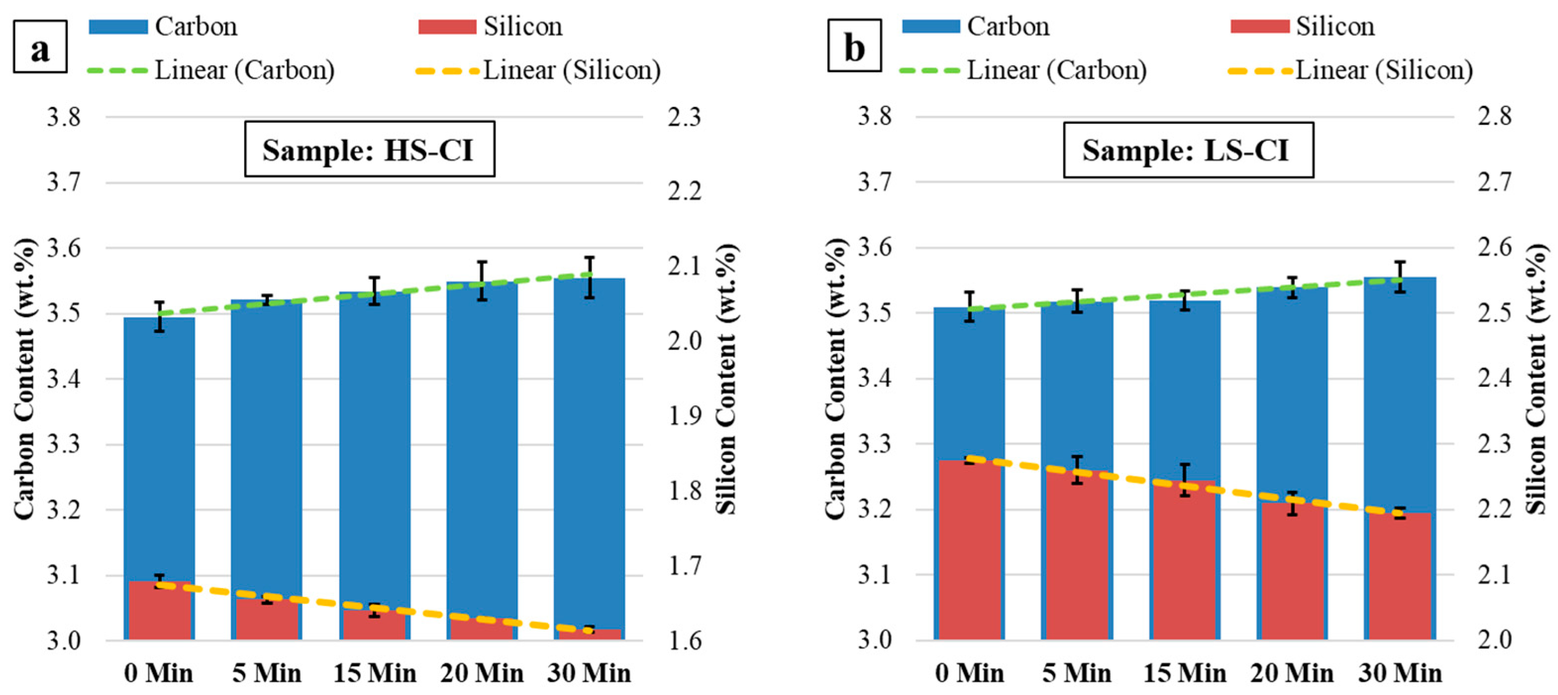
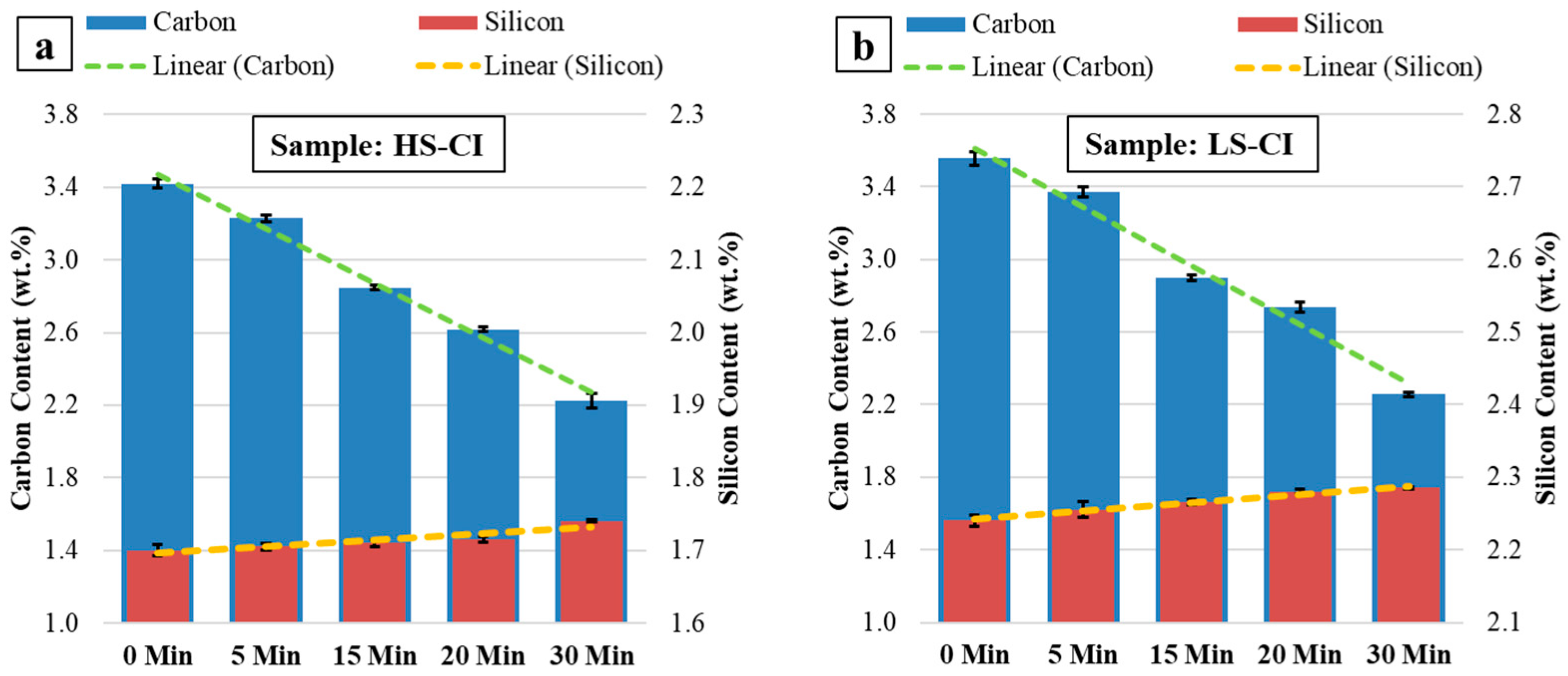
Nonetheless, although a constant carbon content was recorded during high-temperature holding at 1300 °C for both LS-CI and HS-CI, a disparity in silicon concentration was detected instead. The interplay is related to the temperature, yet in a counter way compared with the carbon content, as provided in Figure 2. These results indicate that the silicon content decreases with increasing holding time at 1300 °C. Comparatively, this decreasing tendency of silicon was not observed at 1500 °C, where the highest degree of carbon reduction was recorded instead, as provided in Figure 3.

3.2. Matrix Development and Graphite Structures after ET-Exp

In contrast to the previous section, the following two sections consider only nodular graphite from LS-CI as the subject of study. The focus of this study is based on a separate dedicated report indicating that the dissolution rate of nodular graphite in SGI is slower than that of lamellar graphite in gray cast iron (LGI); however, understanding its mechanism could be contextually adopted to explain the similar dissolution process in HS-CI. Moreover, given the forthcoming results, the dissolution of nodular graphite provides additional insight into its possible heterogeneous nucleation sequence, which is more unsettled than its counterpart.
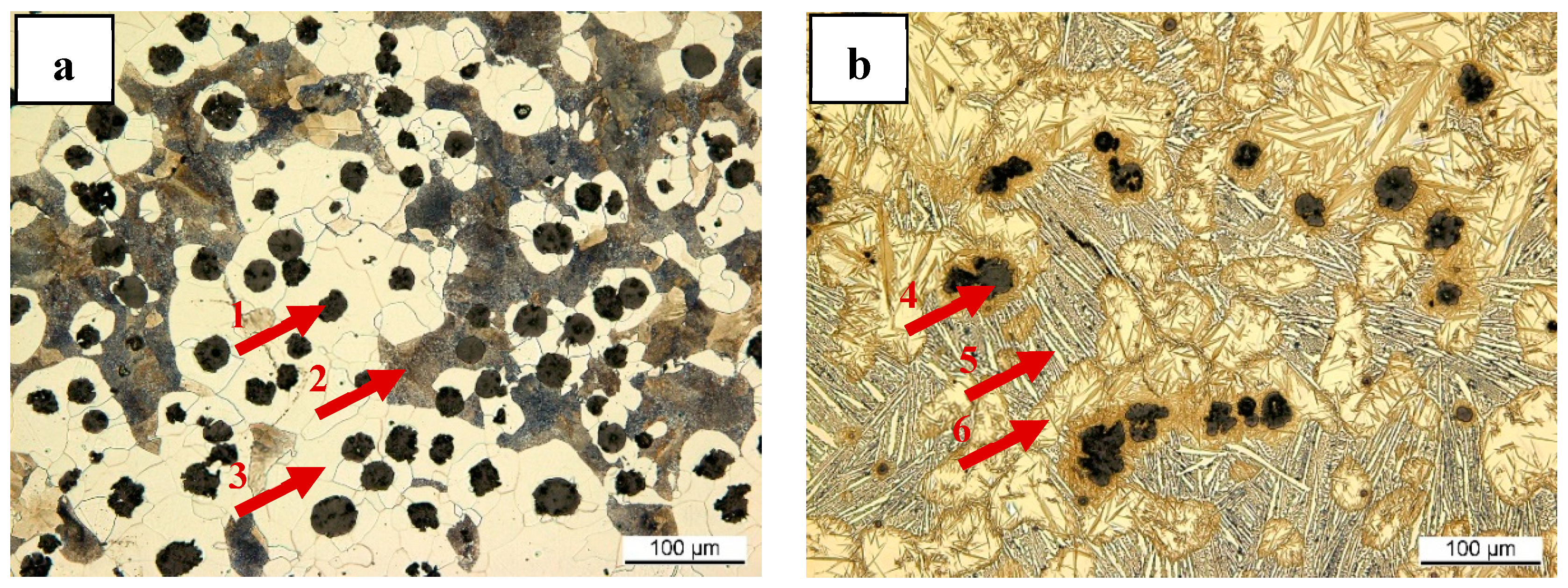
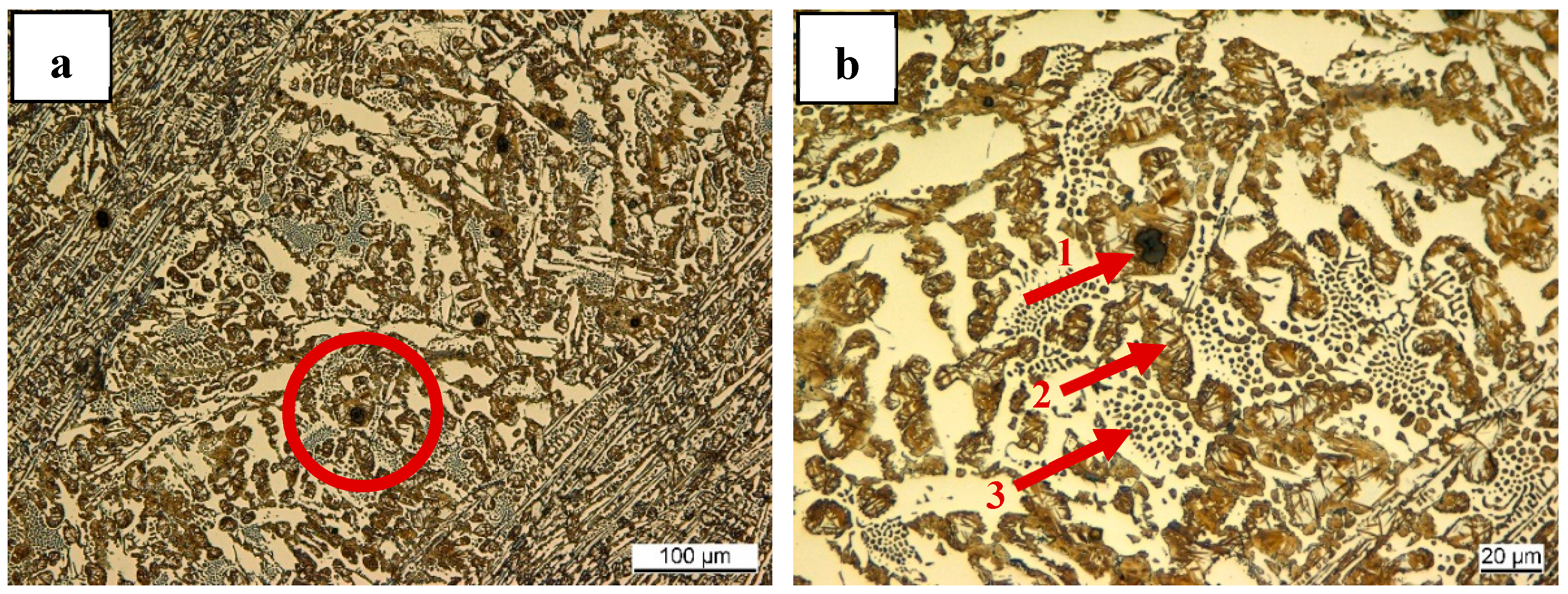
Figure 4 shows the microstructure of the LS-CI sample before and after the heating trials ET-Exp. As indicated in Figure 4a, the as-received LS-CI with a pearlite–ferrite matrix was transformed after 10 min of holding at 1200 °C into a ledeburite–martensite system coupled with residual graphite structures, as represented in Figure 4b. Furthermore, the density of martensite surrounding the residual graphite is greater than that of the former austenite grains, which were eventually transformed into martensite upon water quenching. Considering this former austenite phase, a denser martensite structure is also observed on the edge of the austenite grains, where the ledeburite structure is anticipated to develop.
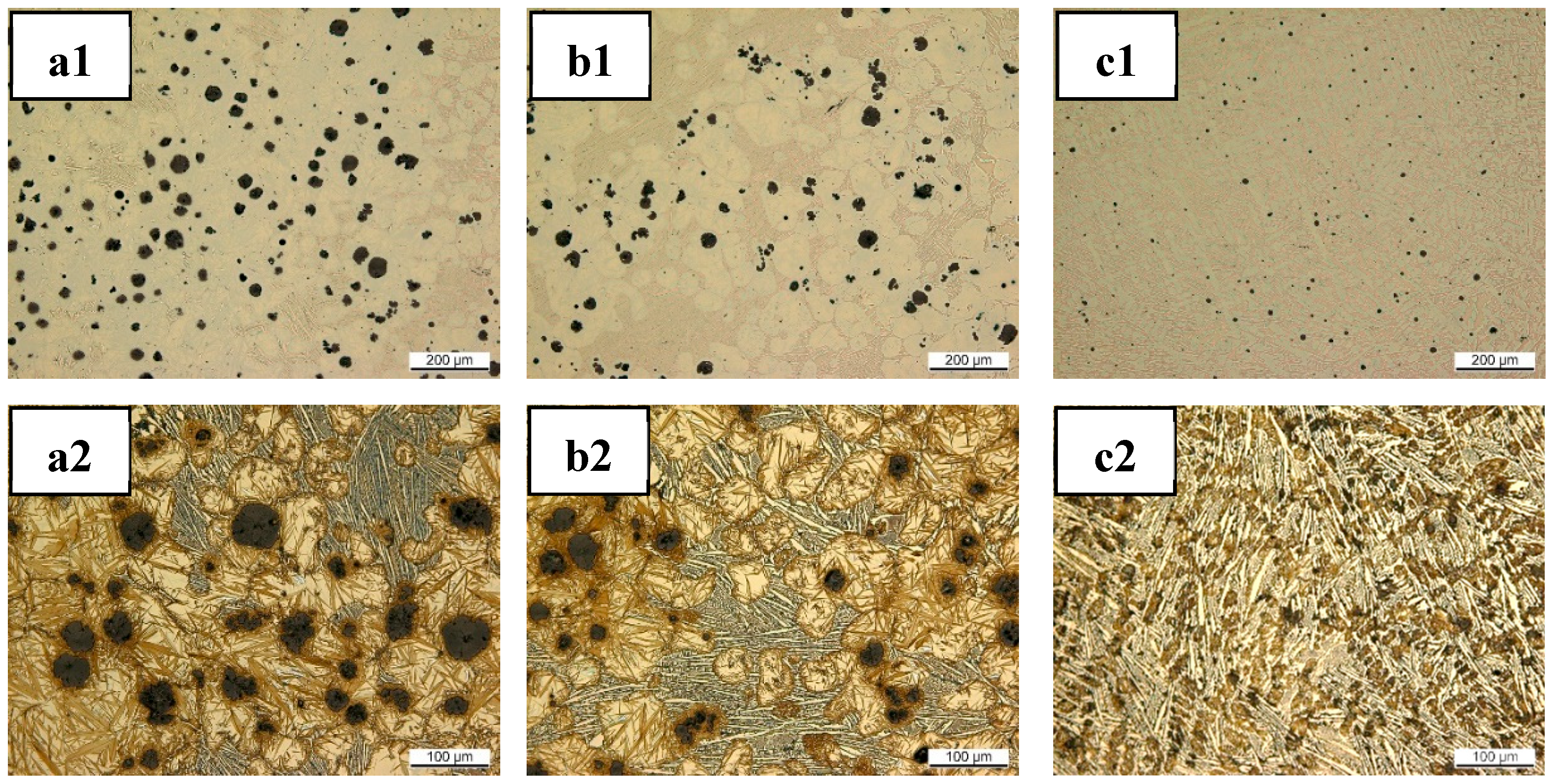
Accordingly, the count of residual nodular graphite after the experiment correlates with the holding duration and temperature. As shown in Figure 5, panels a1–c1, a decreasing tendency in the nodular graphite count is substantiated following a holding duration from 5 to 15 min. Concurrently, as depicted in panels a2–c2, a change in the matrix microstructure related to increasing holding duration is also apparent. These findings indicate that the zone surrounding the graphite transformed into martensite, whereas the remaining matrix region began to exhibit a ledeburite structure. Prolonged holding durations corresponded to an increasing ledeburite proportion and a reduction in the graphite nodule count and size before complete dissolution within a predominant ledeburite matrix, as indicated in Figure 5c2. Notably, even until nearly complete melting, the coverage of the martensite layer encapsulating the rest of the graphite nodule remained detected, as contrasted in Figure 6.
Moreover, the temperature primarily influences the proportion of graphite–martensite–ledeburite during the holding process. As captured in Figure 7a, even with a 15-min holding duration at a lower temperature of 1100 °C, the dominant process was matrix austenitization, represented by a complete martensite structure surrounding the residual graphite nodules (size of around 20 to 40 µm). In contrast, as explored earlier for a holding temperature of 1200 °C, a ledeburite structure is evident in Figure 7b, accompanied by a smaller dimension of graphite nodules (size of <10 µm) yet still engulfed by the martensite phase. This development becomes particularly pronounced at the highest trial temperature of 1300 °C, where the cast iron transforms into an utterly ledeburite structure with the appearance of a primary dendrite constructed by martensite structure originating from a formerly primary austenite phase. This matrix structure is coupled with the unobvious observable existence of the remaining nodular graphite, indicating complete melting, as represented in Figure 7c.

3.3. Observation of the Residual Graphite Structure after ET-Exp

Interestingly, the availability of residual nodular graphite during the ET-Exp experiments provided an additional opportunity to observe the nodular graphite structure. Specifically, since the graphite structures were only partially dissolved, where a surficial reaction mainly governed dissolution, their core was almost perfectly preserved. Therefore, since the size of graphite nodules in some instances is optimally tiny, it increases the likelihood of revealing their core during sample preparation and accelerates the analysis.
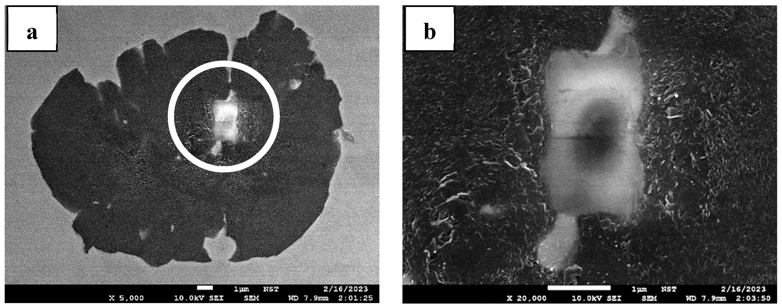
Accordingly, numerous graphite nodules from various treatment temperatures during ET-Exp were subsequently observed using the SEM/EDS. A representative sample from this approach and the most prevalent nonmetallic inclusion configuration found inside a graphite structure during the analysis is depicted in Figure 8. This figure shows a residual graphite nodule with its nucleus exposed. The core was subsequently subjected to chemical analysis, with the results provided in Table 2. This analysis suggests that the nucleus is a nitride particle composed mainly of silicon and magnesium with a slight aluminum trace.

4. Discussion

4.1. Carbon Depletion during High-Temperature Holding

According to the results recorded in Figure 1, Figure 2 and Figure 3, a tendency emerges where either dissolved carbon or silicon in cast iron experiences a concentration change during the holding process and correlates to melting temperatures. As shown in Figure 2, the carbon content slightly increased at 1300 °C, which could be associated with the effect of the clay-graphite crucible used. Conversely, at higher temperatures of 1400 °C and 1500 °C, a decrease in carbon content followed by an insignificant increase in silicon concentration is observed in both samples, as contrasted in Figure 3. It could be explained by considering the compositional constraint effect, given the notable loss in carbon content, as documented in Figure 1.
Furthermore, the decreasing carbon content for HS-CI and LS-CI at the highest studied temperature of 1500 °C can be associated with the oxidation reaction. It is worth mentioning that the effect of the clay-graphite crucible could not even balance the kinetic in carbon reduction, indicated by the comparable decreasing tendency of the LS-CI sample melted at 1400 °C in Figure 1b. In this instance, at high temperatures, the dissolved carbon reacts with the oxygen in the atmosphere, generating CO gas and escaping to the atmosphere. In contrast, at the lowest observed temperature of 1300 °C, the silicon concentration decreased instead of the carbon content in HS-CI and LS-CI. In this case, the oxygen reacted with the dissolved silicon and formed SiO2. However, the reduction in silicon concentration is more moderate than the degree of carbon depletion. This divergence arises from the differing natures of their reaction products. Instead of yielding a gaseous phase (CO), silicon oxidation leads to forming a slag layer (SiO2) covering the surface of molten cast iron, thus preventing further oxidation reactions.
Considering the atmospheric oxygen influx, this interplay in oxidation dynamics during the cast iron melting could also be approached circumstantially by an equilibrium carbothermic reduction reaction of SiO2 known in the foundry industry as the crucible reaction [11,12]. According to this approach, if the temperature of molten cast iron is lower than the equilibrium temperature of the crucible reaction, SiO2 is stable. In another case, carbon will reduce the amount of SiO2 formed, and carbon depletion is expected. Furthermore, since it involves a carbothermic reaction, the equilibrium temperature is correlated with the carbon and silicon contents of the studied cast iron. Concerning the chemical compositions of LS-CI and HS-CI, the equilibrium temperatures were 1420 °C and 1410 °C, respectively. Therefore, at 1500 °C, the carbon content decreases over time during high-temperature holding.
However, emphasis is required to describe the outcomes at 1400 °C since the results do not support the previously mentioned theory. Accordingly, considering the dynamics at the equilibrium temperature, a set of thermodynamic calculations by FactSage was conducted, and the results are compiled in Figure 9. According to the calculation outcomes, comparable results were obtained where silicon dioxide formed at 1300 °C, and the dissolved carbon content decreased at 1500 °C. Employing the approach for a temperature of 1400 °C, the calculation results align with the experimental observation that carbon depletion is expected. The mismatch between the equilibrium temperature based on [11,12] and the thermodynamic calculation can be explained by their different approaches during the oxidation process.
In the crucible reaction, oxidation generally involves the formation of SiO2 before it is subjected to temperature-dependent interactions with dissolved carbon. Nevertheless, oxygen dissolution during melting to form SiO2 did not necessarily occur, as a direct surface reaction upon oxygen influx should be considered; thus, thermodynamic calculations should be more representative. Furthermore, Figure 1 also reported that at 1400 °C, there was a disparity in the degree of carbon reduction between HS-CI and LS-CI. This phenomenon can be associated with the higher silicon content in LS-CI. Despite the oxygen solubility in cast iron reaching its peak at low superheating [13], the higher silicon content in LS-CI limits oxygen solubility but increases carbon activity. Consequently, the perpetuation of oxidation reactions that balance the oxygen influx is preferable, leading to more significant carbon depletion.

4.2. Graphite Dissolution Mechanism of Nodular Graphite

Although rarely systematically explored, the concern of remaining graphite dissolution when circulated cast iron is used as a graphite-containing charge material is not entirely novel in foundry practice [14,15]. Under these circumstances, particular care should be taken during the melting operation if recycled SGI is considered the input material because of the late dissolution of nodular graphite compared with its counterpart in LGI. Specifically, because of the morphological disadvantage of the nodular structure in terms of a lower effective surface area, its dissolution rate is potentially slower than that of lamellar graphite during the remelting process. Moreover, despite the unsettled debate, the main consensus argues that the nodular graphite in SGI exhibits a thickening on the basal plane [16,17,18], where the dissolution of carbon is also expected to be slower than that in the prismatic plane [19,20]. Correspondingly, the significance of the effective surface area is amplified by the results of Figure 5, Figure 6 and Figure 7, which also indicate that the surficial reaction governs the dissolution of nodular graphite. Hence, it is proposed that the initial microstructure of the charged material is a critical factor, especially during the starting sequence of the melting process, in addition to the temperature and heating rate.
According to Wade and Ueda [21], an intermediate austenitization rate is expected in the LS-CI sample because of the initial ferrite–pearlite matrix, as highlighted in Figure 4a. To this extent, as the temperature starts to increase, pearlite dissolution is anticipated to occur primarily at a lower temperature [22] and faster than carbon diffusion from graphite nodules into the ferrite matrix to transform it into austenite. Nonetheless, as the temperature further elevated, the volume diffusion of carbon from the graphite into the surrounding ferrite structure is enhanced. This diffusion is followed by the nucleation of austenite cells on the ferrite grain boundaries and eventually at the graphite/ferrite interface, as suggested in [23,24]. Finally, the mechanism results in a complete austenitic matrix at 1100 °C, accommodating high carbon solubility and transforming into martensite upon water quenching. Nevertheless, it is worth mentioning that establishing austenite does not necessarily consume all the graphite structure since (hence) residual graphite nodules are still observable in Figure 7a.
A significant decrease in the count and size of nodular graphite is eventually detected once a temperature of 1200 °C is considered. As the temperature exceeds the eutectic temperature, the melting process starts concurrently with rejecting dissolved carbon from austenite into the molten phase. As indicated in Figure 4b, the nucleation of the liquid phase began, and the phase grew at the grain boundaries. Interestingly, no liquid phase (indicated as ledeburite) is detected around the graphite, as shown in Figure 6b and Figure 7b, representing the graphite/austenite interface. This result suggests that the carbon enrichment at the graphite/austenite interface might be lower than that at the austenite grain boundaries and be associated with a difference in the melting point. In other words, the diffusion rate of carbon from graphite into the iron matrix is slower than intergranular or intragranular diffusion through the austenite grains. Circumstantially, this disparity in rate could also be associated with the heterogeneity at the graphite/austenite interface, which has been reported to be susceptible to debonding due to thermal and mechanical loading [25,26].
In the case of intragranular diffusion, a carbon concentration gradient is anticipated. In this case, it is indicated that the lowest carbon concentration is in the center of the austenite grains due to the denser martensite structure surrounding the graphite and on the edge of the austenite grains. Consequently, uphill diffusion should be foreseen. Primarily proposed by Darken [27], such uphill carbon diffusion is plausible since a Fe-C-Si system is considered in this case. Considering the initial microstructure of LS-CI and the characteristics of silicon in cast iron, including its inverse segregation behavior and role as a ferrite stabilizer [28,29], an enrichment of silicon is expected in the ferrite structure [30] surrounding the graphite, thus reducing carbon solubility [31] in those particular surrounding areas. Chou et al. [24] also suggested this interchange mechanism to describe carbon enrichment at grain boundaries during the austenitization of ferritic cast iron, as further elucidated by Domeij and Dioszegi [32].
Since graphite is the only carbon source in the studied system, its dissolution is associated with the solubility dynamic in the austenite phase before and after the formation of a liquid state, which sequentially reduces the nodule size, as depicted in Figure 5. As the temperature increases to nearly 1300 °C, an exponential rise in the liquid fraction is eventually anticipated because of the substantial ability of liquid iron to dissolve a notable amount of carbon as molten metal coupled with the decreased amount of dissolved carbon required at austenite/melt equilibrium. Depending on the initial size of the graphite nodules and pearlite–ferrite matrix proportion, some graphite can persist in molten iron and follow the well-established dissolution mechanism. Based on the findings in [33,34], the dissolution of graphite-containing materials in molten iron is determined by the sequence of graphite dissociation followed by a mass transfer of carbon into the bulk of liquid iron. It was also elucidated that mass transfer is the controlling rate; thus, an interfacial layer and local carbon saturation are expected [35].

4.3. Correlation of Homogenization and Oxidation to Fading

The exploration of graphite dissolution reveals that a solid austenite layer surrounding the graphite nodules can still be detected even near the complete melt condition, as documented in Figure 6b and Figure 7c. This investigation suggests that sufficiently high-temperature exposure is necessary during the melting process using recycled SGI since residual graphite can be anticipated if a low melting temperature is applied. Furthermore, this graphite dissolution is considered surficial since iron penetration was unlikely except through any morphological defect, as supported by [35]. No direct oxidation has been reported, but an endothermic reaction was measured during graphite dissolution [19]. Consequently, since the graphite nodule could be protected during the melting process, it is rational to expect their nucleus to be preserved, as depicted in Figure 8.
According to the chemical composition analysis in Table 2, nitride nuclei in graphite stoichiometrically tend to form a phase of MgSiN2 that aligns well with Mercier et al. [36]. A comparable nitride compound is also suggested in [37,38,39], including the coexistence of aluminum. However, the trace amount of aluminum detected in the present study resonates better with that reported by Alonso et al. [40]. Considering these results, the partial dissolution approach to the nodular graphite structure could reliably deliver results similar to the direct observation of graphite nodules and interrupted ductile cast iron solidification process.
The existence of MgSiN2 as a heterogeneous nucleus for nodular graphite can be associated with the magnesium treatment process employing FeSiMg. Since the solubility of magnesium in molten iron is almost negligible [41,42], the Mg in FeSiMg compounds an intermetallic phase of Mg2Si in a matrix of FeSi. This Mg2Si phase is expected to transform into a nitride during the cooling process as it approaches the liquidus temperature [43]. This argument is amplified by Uchida et al. [44]. Based on their observation, the nitridation of Mg2Si starts at 800 °C (stable until ca. 1400 °C), which accords well with the practical circumstances during the nodulizing process (magnesium treatment) immediately before the casting step.
In the context of foundry practice, nitridation could also be favored by decreasing the solubility of nitrogen in molten iron. It has also been reported that reducing nitrogen solubility in liquid Fe-C-Si correlates negatively with increasing carbon and silicon [45,46] contents and elevated temperatures [47]. Since the formation of MgSiN2 occurred in the liquid state, high activities of carbon and silicon are necessary, which can be achieved only by segregation associated with the early-stage dissolution of FeSiMg, as contextually demonstrated in [48]. Based on this perspective, an enriched silicon zone related to the FeSi is anticipated at the dissolution of treatment agents. This process increases both silicon and carbon activities, thus decreasing nitrogen solubility and favoring the nitridation of Mg2Si.
Moreover, since Mg2Si is stable under atmospheric pressure and inert conditions [49], the dissociation of Mg2Si is less probable under the circumstances of the magnesium treatment, except through Mg2Si dissolution in molten iron, which consequently increases the magnesium content in molten iron during this process sequence. Assuming a low concentration of sulfur and oxygen that could be controlled by the magnesium supplied from Mg2Si, silicon segregation can also be established during the early stage of Mg2Si dissolution. This highly localized silicon concentration could increase the nitrogen and carbon activity, thus promoting the formation of MgSiN2 and potentially the nucleation of the graphite structure.
Nevertheless, in the case of prolonged holding and remelting processes, this segregation tends to disperse into the bulk of iron. Consequently, a reduced driving force of nucleation related to local segregation is anticipated because the MgSiN2 solidifies later near the liquidus, and the graphite even requires eutectic undercooling. Therefore, this reduced nucleation potential associated with homogenization might be one determining cause of the fading process coupled with the evaporation susceptibility of dissolved magnesium. Notably, silicon segregation alone cannot ensure the nucleation of nodular graphite [50,51]; instead, a certain amount of dissolved magnesium coupled with this segregation is highly important.
Another fading mechanism could be explained by considering the oxidation process during prolonged holding and remelting processes, as demonstrated earlier in this study. As mentioned, low oxygen activity is required to facilitate direct nitridation; otherwise, the oxidation of Mg2Si is preferable [52,53]. Depending on the dissolved oxygen concentration, the oxidation products of Mg2Si extend between the MgO + Si and MgO.SiO2. Interestingly, the complex formation of MgO. SiO2 could also be expected to be an oxidation product of MgSiN2 at temperatures ranging from 1040 °C to 1400 °C [44]. Following Skaland et al. [54], this MgO.SiO2 possesses a relatively large lattice disregistry to nodular graphite structure and unfavorably acts as a nucleation site. Consequently, this oxidation process can reduce the nucleation potential and should be related to another possible fading mechanism.

5. Conclusions

Based on the investigation results comprised in the present study, the following conclusions could be extracted:
1. Sufficient exposure to high temperatures is necessary to ensure the homogeneity of molten cast iron during the recycling process. However, care must be taken since chemical composition fluctuations are expected due to the reaction with atmospheric oxygen. Specifically, the interplay between dissolved carbon and silicon concentration changes could be anticipated during the remelting process and prolonged holding of molten cast iron, which depends on the operating temperature.
2. The inhomogeneity in molten iron using SGI recycled materials originated from the former graphite structure, which could persist despite already surpassing the eutectic temperature. These findings indicate that the dissolution process is surficial because of the formation of austenite surrounding layer, which can be identified after rapid solidification as a martensite layer covering graphite nodules. Although it starts as early as the austenitization process at low temperatures, the carbon diffusion from the graphite into the matrix is slower than from the austenite into the bulk of the iron.
3. Since the liquid phase starts to nucleate at the grain boundaries of the austenite structure and not at the graphite/austenite interface, partial dissolution of the nodular graphite structure can be achieved with well-preserved nonmetallic nuclei. One of the most commonly detected cores is a nitride particle of MgSiN2, related to the Mg2Si in the FeSiMg treatment agent. Examining the behavior of this MgSiN2 formation and dissolution in molten metal makes it possible to offer an alternative perspective to the fading mechanism, which could be related to the homogenization and oxidation process upon prolonged high-temperature holding and remelting processes.

Author Contributions

I.A.: conceptualization, methodology, validation, formal analysis, investigation, data curation, writing original draft, visualization. N.N.: methodology, validation, investigation, data curation, visualization. R.D.: conceptualization, formal analysis, resources, writing—review and editing, supervision, project administration. All authors have read and agreed to the published version of the manuscript.

Funding

The authors acknowledge support from the Open Access Publication Fund of the University of Duisburg-Essen.

Data Availability Statement

The original contributions presented in the study are included in the article. Further inquiries can be directed to the corresponding authors.

Conflicts of Interest

The authors declare no conflicts of interest.

References

  1. The European Foundry Association. The European Foundry Industry 2022; CAEF: Düsseldorf, Germany, 2023. [Google Scholar]
  2. Umweltbundesamt. Emissionen aus Betrieben der Metallindustrie. The Federal Republic of Germany—Ministry for the Environment, Nature Conservation, Nuclear Safety and Consumer Protection (BMUV), 4 March 2024. Available online: https://www.umweltbundesamt.de/daten/umwelt-wirtschaft/industrie/emissionen-aus-betrieben-der-metallindustrie#das-schadstofffreisetzungs-und-verbringungsregister-prtr-in-deutschland (accessed on 8 August 2024).
  3. Trianni, A.; Cagno, E.; Thollander, P.; Backlund, S. Barriers to Industrial Energy Efficiency in Foundries: A European Comparison. J. Clean. Prod. 2013, 40, 161–176. [Google Scholar] [CrossRef]
  4. Yilmaz, O.; Anctil, A.; Karanfil, T. LCA as a Decision Support Tool for Evaluation of Best Available Techniques (BATs) for Cleaner Production of Iron Casting. J. Clean. Prod. 2015, 105, 337–347. [Google Scholar] [CrossRef]
  5. Zhu, Y.; Keoleian, G.A.; Cooper, D.R. A Parametric Life Cycle Assessment Model for Ductile Cast Iron Components. Resour. Conserv. Recycl. 2023, 189, 106729. [Google Scholar] [CrossRef]
  6. Riposan, I.; Chisamera, M.; Stan, S. Enhanced Quality in Electric Melt Grey Cast Iron. ISIJ Int. 2013, 53, 1683–1695. [Google Scholar] [CrossRef]
  7. Fraś, E.; López, H. Eutectic Cells and Nodule Count—An Index of Molten Iron Quality. Int. J. Met. 2010, 4, 35–61. [Google Scholar] [CrossRef]
  8. Bai, J.-X. Selection of Raw Materials and Control of Trace Elements for Production of High-Quality SG iron. China Foundry 2019, 16, 79–87. [Google Scholar] [CrossRef]
  9. Salonitis, K.; Jolly, M.; Pagone, E.; Papanikolaou, M. Life-Cycle and Energy Assessment of Automotive Component Manufacturing: The Dilemma Between Aluminum and Cast Iron. Energies 2019, 12, 2557. [Google Scholar] [CrossRef]
  10. Jhaveri, K.; Lewis, G.M.; Sullivan, J.L.; Keoleian, G.A. Life Cycle Assessment of Thin-Wall Ductile Cast Iron for Automotive Lightweighting Applications. Sustain. Mater. Technol. 2018, 15, 1–8. [Google Scholar] [CrossRef]
  11. Orths, K.; Weis, W. Bedeutung und Beeinflussung des Kieselsäuregehaltes von Gußeisen. Giessereiforschung 1973, 25, 1–11. [Google Scholar]
  12. Grachev, V.A. Thermodynamics and Mechanism of Silicon Reduction by Carbon in a Crucible Reaction. Orient. J. Chem. 2016, 32, 2929–2937. [Google Scholar] [CrossRef]
  13. Orths, K.; Weis, W. Die Beeinflussung des Kieselsäuregehaltes von Gußeisen durch die Schmelztechnik. Giesserei-Forschung 1973, 25, 9–19. [Google Scholar]
  14. Frost, J.M.; Stefanescu, D.M. Melt Quality Assessment of SG Iron Through Computer-Aided Cooling Curve Analysis. AFS Trans. 1992, 100, 189–200. [Google Scholar]
  15. Stan, S.; Riposan, I.; Chisamera, M.; Barstow, M. Undesirable Graphite Morphologies Incidence in Inoculated Grey Irons. Adv. Mater. Res. 2007, 23, 307–310. [Google Scholar] [CrossRef]
  16. Double, D.; Hellawell, A. The nucLeation and Growth of Graphite—The Modification of Cast Iron. Acta Met. Mater. 1995, 43, 2435–2442. [Google Scholar] [CrossRef]
  17. Amini, S.; Abbaschian, R. Nucleation and Growth Kinetics of Graphene Layers from a Molten Phase. Carbon 2013, 51, 110–123. [Google Scholar] [CrossRef]
  18. Theuwissen, K.; Lacaze, J.; Laffont, L. Structure of Graphite Precipitates in Cast Iron. Carbon 2016, 96, 1120–1128. [Google Scholar] [CrossRef]
  19. Sahajwalla, V.; Khanna, R. A Monte Carlo Simulation Study of Dissolution of Graphite in Iron-Carbon Melts. Met. Mater. Trans. B 2000, 31, 1517–1525. [Google Scholar] [CrossRef]
  20. Jiang, C.; Zhang, J.; Li, K.; Liang, W.; Bi, Z. Influence of Graphite Crystalline Orientation on the Carbon Dissolution Reaction in Liquid Iron: A ReaxFF Molecular Dynamics Simulation Study. J. Mol. Liq. 2021, 335, 115688. [Google Scholar] [CrossRef]
  21. Wade, N.; Ueda, Y. Isothermal Austenitizing of Spheroidal Graphite Cast Iron. Trans. Iron Steel Inst. Jpn. 1980, 20, 849–856. [Google Scholar] [CrossRef]
  22. Miki, T.; Ishii, K. Decomposition Behavior of Fe3C under Ar Atmosphere. ISIJ Int. 2014, 54, 29–31. [Google Scholar] [CrossRef]
  23. Wade, N.; Ueda, Y. Continuous Heating Transformation of Spheroidal Graphite Cast Iron. Trans. Iron Steel Inst. Jpn. 1980, 20, 857–861. [Google Scholar] [CrossRef]
  24. Chou, J.-M.; Hon, M.-H.; Lee, J.-L. The Austenite Transformation in Ferritic Ductile Cast Iron. Mater. Sci. Eng. A 1992, 158, 241–249. [Google Scholar] [CrossRef]
  25. Palkanoglou, E.N.; Baxevanakis, K.P.; Silberschmidt, V.V. Thermal Debonding of Inclusions in Compacted Graphite Iron: Effect of Matrix Phases. Eng. Fail. Anal. 2022, 139, 106476. [Google Scholar] [CrossRef]
  26. Warmuzek, M.; Polkowska, A. Micromechanism of Damage of the Graphite Spheroid in the Nodular Cast Iron During Static Tensile Test. J. Manuf. Mater. Process. 2020, 4, 22. [Google Scholar] [CrossRef]
  27. Darken, L.S. Diffusion of Carbon in Austenite with a Discontinuity in Composition. Met. Technol. 1948, 430–438. [Google Scholar] [CrossRef]
  28. Franzen, D.; Weiß, P.; Pustal, B.; Bührig-Polaczek, A. Modification of Silicon Microsegregation in Solid-Solution-Strengthened Ductile Iron by Alloying with Aluminum. Int. J. Met. 2020, 14, 1105–1114. [Google Scholar] [CrossRef]
  29. Arshad, W.; Mehmood, A.; Hashmi, M.F.; Rauf, O.u. The Effect of Increasing Silicon on Mechanical Properties of Ductile Iron. J. Physic IOP Conf. Ser. 2018, 1082, 012059. [Google Scholar] [CrossRef]
  30. Alhussein, A.; Risbet, M.; Bastien, A.; Chobaut, J.; Balloy, D.; Favergeon, J. Influence of Silicon and Addition Elements on the Mechanical Behavior of Ferritic Ductile Cast Iron. Mater. Sci. Eng. A 2014, 605, 222–228. [Google Scholar] [CrossRef]
  31. Ahn, S.H.; Kim, Y.H.; Shin, J.-P.; Lee, Y.E. Thermodynamic Assessment of Liquid Fe-Si-C System by Unified Interaction Parameter Model. ISIJ Int. 2014, 54, 750–755. [Google Scholar] [CrossRef]
  32. Domeij, B.; Diószegi, A. The Distribution of Carbon in Austenite Studied on a Water-Quenched Compacted Graphite Iron using Electron Probe Microanalysis. Int. J. Met. 2020, 14, 782–793. [Google Scholar] [CrossRef]
  33. Kosaka, M.; Minowa, S. On the Rate of Dissolution of Carbon into Molten Fe-C Alloy. Trans. Iron Steel Inst. Jpn. 1968, 8, 392–400. [Google Scholar] [CrossRef]
  34. Sun, H. Factors influencing dissolution of carbonaceous materials in liquid iron. Met. Mater. Trans. B 2005, 36, 893–894. [Google Scholar] [CrossRef]
  35. Sun, M.-M.; Zhang, J.-L.; Li, K.-J.; Ren, S.; Wang, Z.-M.; Jiang, C.-H.; Li, H.-T. Dissolution Behaviours of Various Carbonaceous Materials in Liquid Iron: Interaction Between Graphite and Iron. JOM 2019, 71, 4305–4310. [Google Scholar] [CrossRef]
  36. Mercier, J.C.; Paton, R.; Margerie, J.C.; Mascre, C. Inclusions dans les spheroides de graphite. Fonderie 1969, 277, 191–200. [Google Scholar]
  37. Igarashi, Y.; Okada, S. Observation and Analysis of the Nucleus of Spheroidal Graphite in Magnesium-Treated Ductile Iron. Int. J. Cast Met. Res. 1998, 11, 83–88. [Google Scholar] [CrossRef]
  38. Solberg, J.; Onsøien, M. Nuclei for Heterogeneous Formation of Graphite Spheroids in Ductile Cast Iron. Mater. Sci. Technol. 2001, 17, 1238–1242. [Google Scholar] [CrossRef]
  39. Laffont, L.; Pugliara, A.; Hungria, T.; Lacaze, J. STEM Observation of a Multiphase Nucleus of Spheroidal Graphite. J. Mater. Res. Technol. 2020, 9, 4665–4671. [Google Scholar] [CrossRef]
  40. Alonso, G.; Tokarski, T.; Stefanescu, D.; Górny, M.; Cios, G.; Suarez, R. On the Crystallography of the Mg-Si-Al Nitride Nuclei and of the Graphite/Nitride Interface in Spheroidal Graphite Iron. Carbon 2022, 199, 170–180. [Google Scholar] [CrossRef]
  41. Zhang, X.; Han, Q.; Chen, D. Dissolution Equilibrium of Magnesium V Por in Liquid Iron. Met. Trans. B 1991, 22, 918–921. [Google Scholar] [CrossRef]
  42. Mikhailov, G.G.; Samoilova, O.V.; Makrovets, L.A.; Smirnov, L.A. Thermodynamic Modeling of Isotherms of Oxygen Solubility in Liquid Metal of the Fe–Mg–Al–O System. Steel Transl. 2019, 49, 522–527. [Google Scholar] [CrossRef]
  43. Qing, J.; Lekakh, S.; Xu, M.; Field, D. Formation of Complex Nuclei in Graphite Nodules of Cast Iron. Carbon 2021, 171, 276–288. [Google Scholar] [CrossRef]
  44. Uchida, H.; Itatani, K.; Aizawa, M.; Howell, F.S.; Kishioka, A. Synthesis of Magnesium Silicon Nitride by the Nitridation of Powders in the Magnesium-Silicon System. J. Ceram. Soc. Jpn. 1997, 105, 934–939. [Google Scholar] [CrossRef]
  45. Maekawa, S.; Nakagawa, Y. Solubility of Nitrogen in Liquid Iron and Effect of Carbon, Silicon and Manganese on the Solubility. Tetsu-to-Hagane 1960, 46, 748–753. [Google Scholar] [CrossRef] [PubMed]
  46. Jang, J.-M.; Kim, D.-H.; Paek, M.-K.; Pak, J.-J. Nitrogen Solubility in Cast Iron Containing C, Si and Mn. ISIJ Int. 2018, 58, 1185–1190. [Google Scholar] [CrossRef]
  47. Paek, M.-K.; Jeon, J.; Lindberg, D. Thermodynamic Behaviour of Nitrogenin the Carbon Saturated Fe-Mn-Si Alloy during Casting. Int. J. Cast Met. Res. 2020, 33, 226–232. [Google Scholar] [CrossRef]
  48. Prijanovič, M.T.; Mrvar, P.; Burja, J.; Donik, Č.; Petrič, M. Study on Dissolution of Ba-Containing Inoculant in Ductile Cast Iron Melt and Nucleation of Graphite. Int. J. Met. 2023, 1–11. [Google Scholar] [CrossRef]
  49. Hwang, S.-M.; Park, S.-J.; Kim, G.-T.; Kim, H.-N.; Ko, J.-W.; Park, Y.-H.; Lee, D.-W. Metallic Silicon Powder Produced by Vacuum Decomposition of Magnesium Silicide Prepared by Magnesiothermic Reduction. Mater. Trans. 2021, 62, 1285–1290. [Google Scholar] [CrossRef]
  50. Cochard, V.; Harding, R.; Campbell, J.; Hérold, R. Inoculation of Spheroidal Graphite Cast Iron. Adv. Mater. Res. 1997, 4–5, 277–284. [Google Scholar] [CrossRef]
  51. Fras, E.; López, H.F.; Podrzucki, C. The Influence of Oxygen on the Inoculation Process of Cast Iron. Int. J. Cast Met. Res. 2000, 13, 107–121. [Google Scholar] [CrossRef]
  52. Stathokostopoulos, D.; Chaliampalias, D.; Pavlidou, E.; Paraskevopoulos, K.M.; Chrissafis, K.; Vourlias, G. Oxidation resistance of magnesium silicide under high-temperature air exposure. J. Therm. Anal. Calorim. 2015, 121, 169–175. [Google Scholar] [CrossRef]
  53. Stefanaki, E.-C.; Hatzikraniotis, E.; Vourlias, G.; Chrissafis, K.; Kitis, G.; Paraskevopoulos, K.M.; Polymeris, G.S. Thermal Stability Study from Room Temperature to 1273 K (1000 °C) in Magnesium Silicide. Met. Mater. Trans. A 2016, 47, 5146–5158. [Google Scholar] [CrossRef]
  54. Skaland, T.; Grong, Ø.; Grong, T. A Model for the Graphite Formation in Ductile Cast Iron: Part I. Inoculation Mechanisms. Met. Trans. A 1993, 24, 2321–2345. [Google Scholar] [CrossRef]
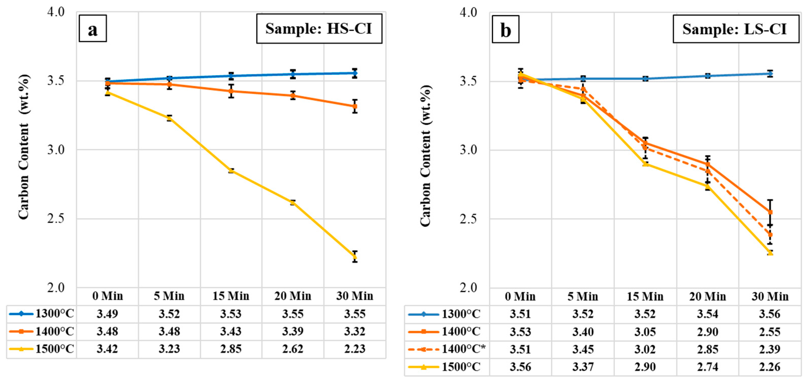
Figure 1. The average change in the carbon content during the high-temperature holding of (a) HS-CI and (b) LS-CI—additional sample LS-CI 1400 °C* was melted in an alumina-based crucible.
Metals 14 00915 g001
Figure 2. The average change in the carbon and silicon contents in (a) HS-CI and (b) LS-CI during holding at a temperature of 1300 °C.
Metals 14 00915 g002
Figure 3. The average change in the carbon and silicon contents in (a) HS-CI and (b) LS-CI during holding at a temperature of 1500 °C.
Metals 14 00915 g003
Figure 4. Microstructure of nital-etched LS-CI (a) before and (b) after ET-Exp (1200 °C for 10 min)—transforming (1) nodular graphite in (2) pearlite and (3) ferrite matrix system into (4) residual graphite in (5) ledeburite and (6) martensite matrix system.
Metals 14 00915 g004
Figure 5. Microstructure development LS-CI after being held at 1200 °C followed by water quenching for (a1) 5, (b1) 10, and (c1) 15 minutes in as-polished condition as well as for (a2) 5, (b2) 10, and (c2) 15 minutes in nital-etched condition.
Metals 14 00915 g005
Figure 6. Microstructure of the nital-etched LS-CI after 15 minutes of holding at 1200 °C followed by water quenching indicating (a) residual graphite in red circle detailed in (b): (1) graphite, (2) martensite, and (3) ledeburite.
Metals 14 00915 g006
Figure 7. Microstructure of the nital-etched LS-CI after 15 minutes of holding at (a) 1100 °C, (b) 1200 °C, and (c) 1300 °C followed by water quenching—detailed red arrow G: residual graphite.
Metals 14 00915 g007
Figure 8. (a) Rest nodular graphite and (b) detail of its nonmetallic nucleus in the LS-CI sample.
Metals 14 00915 g008
Figure 9. FactSage calculation results for the oxidation of HS-CI and LS-CI at explored temperatures.
Metals 14 00915 g009
Table 1. Initial chemical composition (wt.%) of cast iron samples.
CSiSP MnFe
LS-CI3.4–3.62.2–2.3<0.0050.02–0.030.10–0.1593–94
HS-CI3.4–3.51.6–1.70.10–0.120.06–0.070.5–0.693–94
Table 2. The chemical composition (wt.%) of the nonmetallic graphite nucleus in Figure 8b.
C SiMgNAlFe
Nucleus11–1736–3724–2534–381.0–1.51.0–3.0
Disclaimer/Publisher’s Note: The statements, opinions and data contained in all publications are solely those of the individual author(s) and contributor(s) and not of MDPI and/or the editor(s). MDPI and/or the editor(s) disclaim responsibility for any injury to people or property resulting from any ideas, methods, instructions or products referred to in the content.