Communication

Solving the Solidification Cracking in Maraging Steel during Mass Production by Adjusting High-Temperature Delta Ferrite

1
State Key Laboratory of Rolling and Automation, Northeastern University, Shenyang 110819, China
2
Department of Materials Physics and Chemistry, School of Materials Science and Engineering, Northeastern University, Shenyang 110819, China
3
Fushun Special Steel Co., Ltd., Fushun 113001, China
4
Easyforming Materials Technology Co., Ltd., Suzhou 215123, China
*
Authors to whom correspondence should be addressed.
Metals 2024, 14(9), 1020; https://doi.org/10.3390/met14091020
Submission received: 26 June 2024 / Revised: 22 August 2024 / Accepted: 4 September 2024 / Published: 6 September 2024

Abstract

:
Maraging steels hardened by Cu + NiAl precipitation have recently garnered attention owing to their relatively low cost and exceptionally high strength. However, the high alloy content can cause issues such as solidification cracking, particularly in mass production. In this study, solidification cracking was observed in a Cu + NiAl-hardened maraging steel manufactured via an electroslag remelting process, and an improvement strategy was adopted to solve this problem. Increasing the aluminum content from 1.0 wt.% to 1.2 wt.% can adjust the δ ferrite, which affects the thermal expansion coefficient and density of the system, thereby reducing the rate of cooling shrinkage. The extra addition of 0.2 wt.% aluminum had a negligible effect on the final microstructure and mechanical properties, with both steels demonstrating excellent tensile properties. The reduction in internal stress from the increased aluminum content was also confirmed using X-ray diffraction (XRD) measurement and the finite element method (FEM). This strategy provides valuable insights for the manufacturing of such high-alloy steels on a mass production scale.

1. Introduction

As early as the 1960s, maraging steel was developed and then put into production. It has been widely used in high-pressure vessels, bearings, molds, and other applications. Its widespread use, however, has been constrained by the high cost associated with its significant cobalt content [1,2]. Recently, there has been significant interest in the cost-effectiveness and enhanced performance of maraging steel featuring co-precipitation Cu + NiAl or only NiAl [3,4,5,6,7,8]. However, research has primarily focused on its alloy design, precipitation evolution, and strengthening mechanisms.
In practical application, particularly in mass production, smelting challenges are inevitable for this high-alloy-content maraging steel [9]. The increased alloy content results in reduced liquidity of the molten metal, which, if insufficient to offset the volume shrinkage during solidification, can lead to the development of tensile stress and subsequent cracking [10]. To date, there has been a lack of research addressing the smelting cracking of Cu + NiAl maraging steel. Therefore, this study proposes a solidification crack mitigation strategy that addresses the cracking issue in the large-scale production of Cu + NiAl maraging steel. The strategy is also promising for the production of other high-alloy steels.

2. Materials and Methods

2.1. Design of Materials

Thermodynamic calculations provide an effective method to readily predict phase relationships in multi-component alloys [11,12]. In this study, the Thermo-Calc 2023a software with Fe database (TCFE 9.3) was employed to provide guidelines for alloy design. Each step of the alloy design procedure is presented below.
First, the carbon content of the steel was set based on the consideration of both weldability and carbide hardening. Carbon is known as one of the most important alloying elements affecting steel weldability, and high-carbon steels tend to suffer from solidification cracking in welds [13]. Similar to the carbon level in the weldable, high-strength steels Navy HSLA-80 and HSLA-100 [14], a low carbon content of 0.05 wt.% was set for high weldability. Additionally, to prevent the formation of cementite and to ensure good ductility, strong carbide-forming elements, including Nb and Mo, were introduced into the steel. As suggested by commercial precipitation-hardening martensitic steels [5], a combination of 0.02 wt.% Nb and Mo was added to form nanoscale alloy carbides.
Second, Cu precipitation characteristics are strongly dependent on the Cu supersaturation and aging conditions used. The fraction of the Cu phase as a function of Cu content and heat treatment temperature was calculated employing Thermo-Calc, as shown in Figure 1. At 1000 °C, the Cu phase started to precipitate out when the Cu content exceeded 5.0 wt.%. Cu has a low melting point (~1082 °C) compared to the a-Fe matrix, and excessive Cu additions tend to cause a hot cracking phenomenon known as hot shortness [15,16]. Thus, to study the effect of the maximum content of Cu, the main alloying element, on large shrinkage-induced cracking, a 5 wt.% Cu element was added. In addition, the Ni was necessary for avoiding hot shortness, and the mass ratio of Cu to Ni is usually greater than 0.5 [17,18].
Finally, the content of Al was optimized to promote the formation of NiAl-type nanoparticles while minimizing the formation of undesired phases including δ ferrite. It was noted that Al, a ferrite stabilizer, at higher content, would lead to the retention of δ ferrite during solution and aging treatment, even a small fraction of δ ferrite seriously worsened the toughness [19]. To predict the allowable Al content, the composition range fulfilling the requirements for δ ferrite was used, as shown in Figure 2; the fraction of δ ferrite at 900 °C increased with higher Al content and lower Ni content, and the composition with 2.5 wt.% Ni and less than 1.25 wt.% Al was enough for retarding the formation of δ ferrite. In addition, the pseudo-binary phase diagram of Fe-0.05C-0.5Mo-0.02Nb-5Cu-2.5Ni-2Al was calculated by means of Thermo-Calc, presented in Figure 3, when Al content was less than 0.93 wt.%, the peritectic reaction would occur. Therefore, the final optimal compositions were derived as Fe-0.05C-0.5Mo-0.02Nb-5.0Cu-2.5Ni-1.0/1.2Al (wt.%). Although avoiding the inclusion reaction, adding 1.0 wt.% Al made the δ iron region narrow. The addition of 1.2 wt.% Al may result in the best strengthening effect of NiAl precipitation.

2.2. Experimental Methods

Two steels were melted in a 6-ton vacuum induction furnace and cast into two 250 mm diameter electrode ingots, each weighing approximately 1.2 tons. They were then refined by electroslag remelting in an argon atmosphere, producing ingots with a diameter of 330 mm and a weight of approximately 2 tons, after slag removal from the surface. Their actual chemical compositions were Fe-0.05C-0.52Mo-0.02Nb-5.02Cu-2.44Ni-1.01Al and Fe-0.05C-0.53Mo-0.02Nb-4.98Cu-2.44Ni-1.19Al (wt.%), denoted as 1.0Al and 1.2Al, respectively.
The macro-residual stress of the cast ingots was measured using X-ray diffraction (XRD, PROTO, Taylor, MI, USA), with the testing location for 1.0Al steel being near the tip of the crack. The residual stress was measured over a circular area with a diameter of 3 mm. For thermal property analysis, Φ 3 × 4 mm samples in alumina crucibles underwent differential scanning calorimetry (DSC, 1600-DTA, SETARAM, Lyon, France) in an argon flow of 30 cm3∙min−1 to prevent oxidation. The samples were heated to 1550 °C at 10 °C ∙min−1, held for 3 min, and then cooled at 1 °C∙min−1. After mechanical polishing, the microstructures of 1.0Al and 1.2Al ingots were characterized using optical microscopy (OM, Olympus BX41M, Olympus, Tokyo, Japan) and an electron probe micro-analyzer (EMPA, JEOL JXA-8530F, JEOL, Tokyo, Japan).
Due to the complex temperature and stress fields in electroslag cast ingots, the sample size and experimental procedure of DSC experiments were used to simplify the finite element method (FEM) analysis. This approach was used to study the effect of the coefficient of thermal expansion and density on thermal stress in 1.0Al and 1.2Al steel. Under linear cooling, the temperature field was found to be independent of the ingot size. The thermal stress distribution during cooling from 1450 °C to 1270 °C at 1 °C∙min−1 was analyzed using the FEM software ABAQUS 2019. The Young’s modulus and Poisson ratio were set to 111 GPa and 0.3 at a temperature just after solidification, respectively. In this study, only the effects of density and the thermal expansion coefficient were considered in the FEM. A C3D8T hexahedral mesh with fully constrained surface boundaries was employed to simulate the outer solidification.
The tensile test was conducted on the forged experimental steel at room temperature to assess its tensile properties. The test was performed using a SUNS (UTM5105) 100 KN mechanical testing device with extensometer at a strain rate of 1 × 10⁻³ s−1. The rod tensile samples with a diameter of 5 mm and a gauge length of 40 mm were used. Three parallel tests were conducted under each condition to verify reliability.

3. Results and Discussion

The ingots of 1.0Al and 1.2Al steels are presented in Figure 4a and Figure 4b, respectively; the internal microstructures of both ingots are ferritic (Figure 4c,d). The average grain size of 1.0Al steel is 168.6 ± 39.8 μm, and that of 1.2Al steel is 160.8 ± 37.8 μm. Therefore, the Al content had a negligible effect on the grain sizes for the casting microstructure of 1.0Al and 1.2Al ingots. Under the same casting process conditions, the 1.2Al ingot exhibited a good surface quality, whereas the surface of the 1.0Al ingot displayed an obvious thermal crack. Upon the removal of the surface layer, it was found that the cracks of 1.0Al extended to the interior of the ingot (Figure 4e). The OM micrograph revealed the lath martensite near the crack, caused by the faster thermal exchange between the crack area and the external regions, leading to a higher cooling rate than in the core. Additionally, an oxidation layer with a thickness of 56.3 ± 1.4 μm was observed, and the elemental distribution within this layer was analyzed using EPMA (Figure 4f). The outer layer is enriched with higher levels of oxygen and iron elements. Therefore, it was determined to be iron oxide. In the subsurface layer, the oxygen content was reduced compared to the outermost layer, while the content of iron was slightly increased. Additionally, in this layer, the contents of copper, nickel, aluminum, and molybdenum were enriched compared to the inner matrix layer, with noticeable segregation observed especially for copper and nickel. High temperatures facilitate rapid diffusion of elements, leading to the enrichment of alloy elements in the subsurface layer as a direct result of selective oxidation processes. The segregation of copper and nickel could promote the formation of compounds involving these elements. In summary, the presence of an outer oxidation layer indicated that cracks formed during the high-temperature solidification process and underwent further oxidation during subsequent cooling.
Subsequently, the cause of the solidification cracking in 1.0Al was analyzed. The equilibrium phase fractions of two steels were calculated by means of Thermo-Calc (Figure 5a). It revealed that both of them undergo the transformation of liquid (L) → δ ferrite → austenite (γ), and no peritectic reaction of L + δ → γ occurred, which was consistent with the pseudo-binary phase diagram in Figure 3. Furthermore, the temperature region of single δ ferrite in 1.0Al was 1450.6–1475.9 °C, which was narrower than that of 1420.9–1477.7 °C in 1.2Al steel. This was due to the fact that higher Al content stabilized the ferrite and decreased the starting temperature of the δ → γ transformation. The transformation finishing temperature decreased from 1348.5 °C to 1277.4 °C with the increase in Al content. The DSC measurement revealed a similar tendency with the calculated results (Figure 5b), and it also confirmed ferrite as the final microstructure (Figure 4c,d and Figure 5c). This difference in phase fraction in the high-temperature region could affect the solidification behavior.
It is well known that ferrite and austenite exhibit distinct physical properties, leading to differences between the two steels due to the variation in δ and γ fractions (Figure 5a). Firstly, the two steels display different changes in the thermal expansion coefficients, as shown in Figure 5d. During the solid–liquid phase transition, there was a significant volume contraction, resulting in a higher thermal expansion coefficient at this stage. The 1.0Al steel exhibited a larger expansion coefficient during solidification; hence, it showed more significant volume contraction. However, in the single-phase stage, the expansion coefficient of 1.0Al was slightly smaller due to aluminum’s effect on increasing the expansion coefficient. As the temperature further decreased in the δ + γ region, 1.0Al steel exhibited a wider higher expansion coefficient range. Notably, at 1450 °C, the thermal expansivity of 1.0Al steel reached 47.5 × 10⁻⁶, while that of 1.2Al steel only reached 20.3 × 10⁻⁶, which was more than twice that of 1.2Al steel, because of the larger shrinkage coefficient of austenite [20]. Additionally, the density variation was calculated (Figure 5e). The stabilizing effect of aluminum on ferrite resulted in a lower density for 1.2Al, as ferrite has a lower density than austenite [21]. At the same temperature, the density of 1.0Al steel was only about 0.7% higher than that of 1.2Al steel. Therefore, the additional 0.2% Al did not cause a significant change in density. Due to the higher starting temperature of transformation to the high-density austenite in 1.0Al, the rate of density increase was faster. Consequently, 1.2Al steel exhibited a broader temperature range for the presence of δ ferrite due to the stabilizing effect of higher aluminum content. This resulted in a lower thermal expansion coefficient and density, which in turn reduced the rate of volume contraction during solidification and subsequent cooling. Consequently, the occurrence of solidification cracking was minimized.
The residual stress in both casts was measured using XRD, which revealed tensile stress within both casts. Due to cracking during solidification of 1.0Al, the measurement was taken near the crack tip. Despite this, the residual stress in the 1.2Al cast was 288 ± 15 MPa, significantly lower than the 374 ± 32 MPa residual stress in the 1.0Al cast. The FEM was also utilized to analyze the stress distribution, with the findings illustrated in Figure 6. During the cooling process in the high-temperature region, the L → δ and δ → γ transformation induced the occurrence of thermal stress. For the 1.0Al steel, the maximum von Mises equivalent stress reached 6.17 × 10⁻¹¹ MPa at 1270 °C, whereas for the 1.2Al steel, this value was significantly lower at 1.82 × 10⁻¹¹ MPa. The thermal stress of 1.0Al was more than three times that in 1.2Al. Moreover, the stress distribution in 1.0Al was notably less uniform compared to that in 1.2Al steel. These results suggested that the higher aluminum content in 1.2Al steel effectively reduced internal stress during the cooling transformations, thereby diminishing the likelihood of cracking. This insight highlights the critical role of aluminum in enhancing the structural integrity of high-alloy maraging steels during thermal processing.
Two blocks with the size of 100 mm × 100 mm × 200 mm were cut from 1.0Al and 1.2Al ingots. The 1.0Al steel block was cut to avoid the crack zone. The forging process began after the two blocks were soaked at 1050 °C for 8 h. Deformation occurred in all three directions (X-Y-Z), with a deformation of 50%. The final forging temperature was approximately 900 °C. The forged blocks were then air-cooled to room temperature. Two types of tensile specimens were prepared from the cores of the forged blocks. These tensile specimens were water-quenched after being soaked at 950 °C for 1 h, aged at 450 °C for 12 h, and finally air-cooled to room temperature. The tensile curves for the 1.0Al and 1.2Al steels are presented in Figure 7. The 1.2Al steel demonstrated a yield strength of 1470 ± 14 MPa, a tensile strength of 1538 ± 38 MPa, and a total elongation of 10.4 ± 0.2%. Similarly, the 1.0Al steel exhibited a yield strength of 1472 ± 13 MPa, a tensile strength of 1537 ± 35 MPa, and a total elongation of 10.3 ± 0.3%. The Cu + NiAl co-precipitation maraging steel exhibited excellent strength and ductility. Similar materials have been reported in other studies. For instance, Yang et al. [22] designed a Cu + NiAl-precipitated maraging steel that achieved a tensile strength of 1584.5 MPa and an elongation of 11.4%. Niu et al. [23] reported a maraging steel with a tensile strength of 1330 MPa and an elongation of 16%. Both steels exhibited the characteristic strength–ductility profiles of maraging steels and held significant potential for structural applications [1,9,24].

4. Conclusions

In this study, the solidification cracking and the improvement mechanism of Cu+NiAl precipitation-hardened martensitic aging steel during mass production were investigated. The following conclusions can be drawn from the current study:
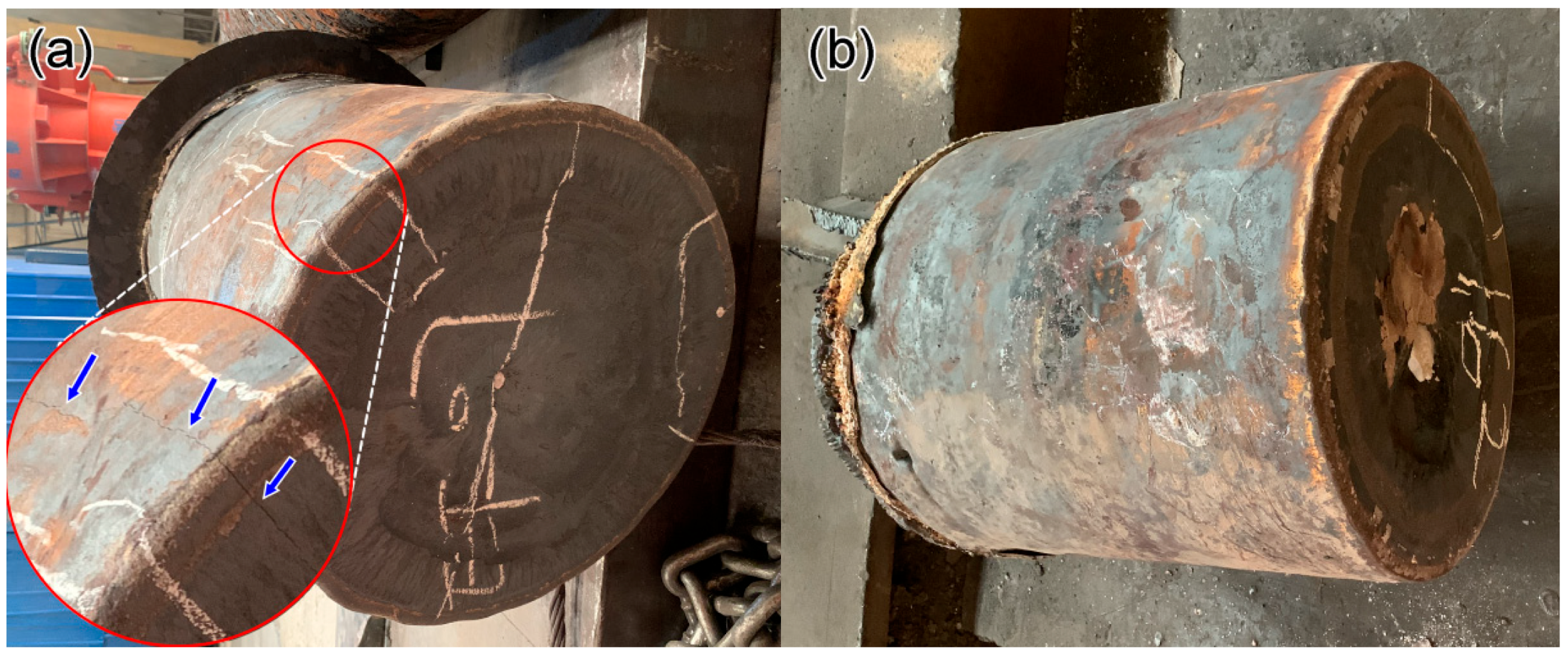
  • The solidification cracks were observed in 1.0Al steel during the high-temperature solidification process, which subsequently oxidized during the cooling process. This defect was a significant challenge, compromising the structural integrity of the steel.
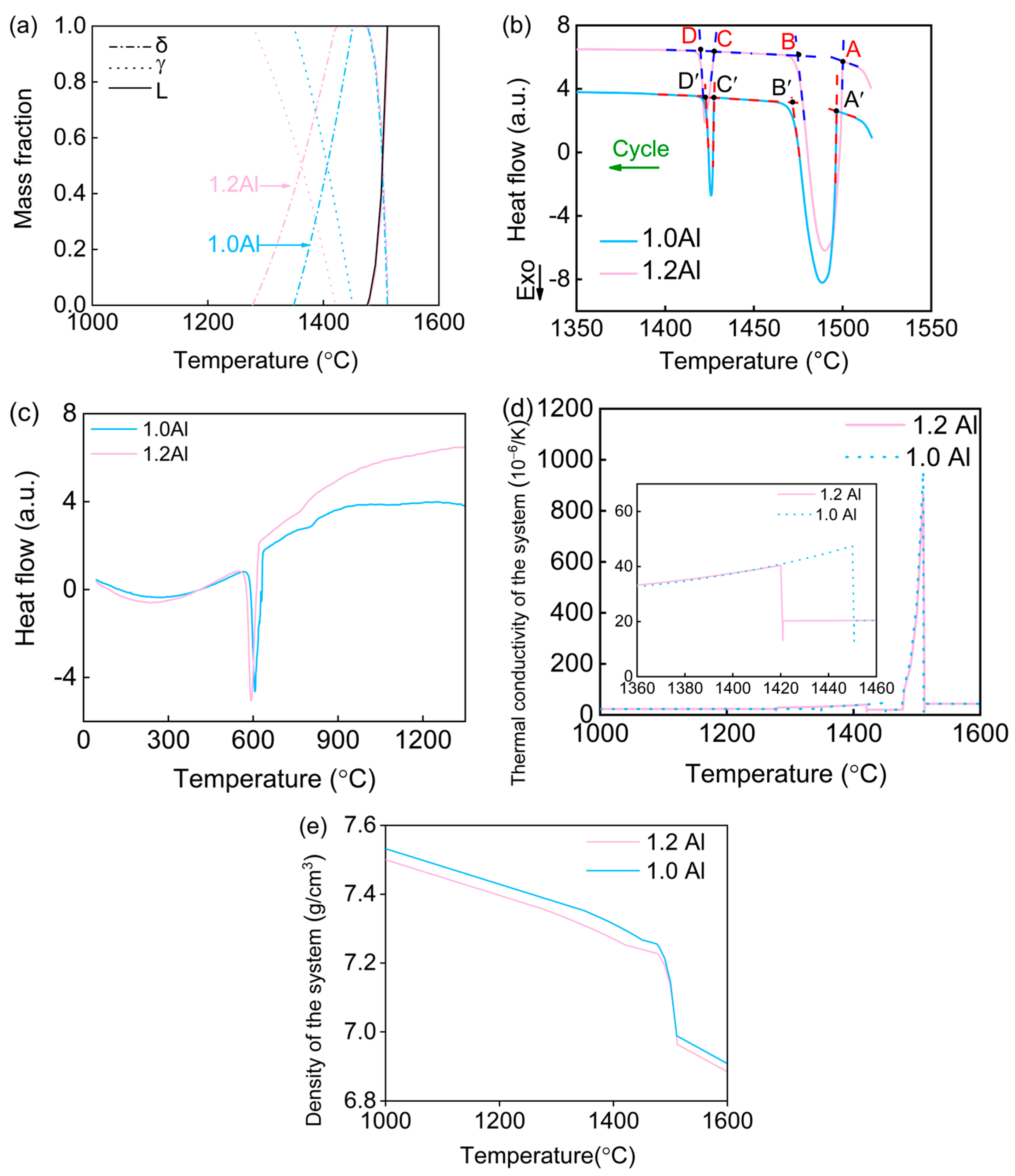
  • By increasing the aluminum content to 1.2 wt.%, the issue of crack formation was effectively mitigated. This is due to the fact that aluminum can expand the δ ferrite region and lower the δ → γ transformation temperature. This microstructural adjustment played a crucial role in addressing the cracking issue.
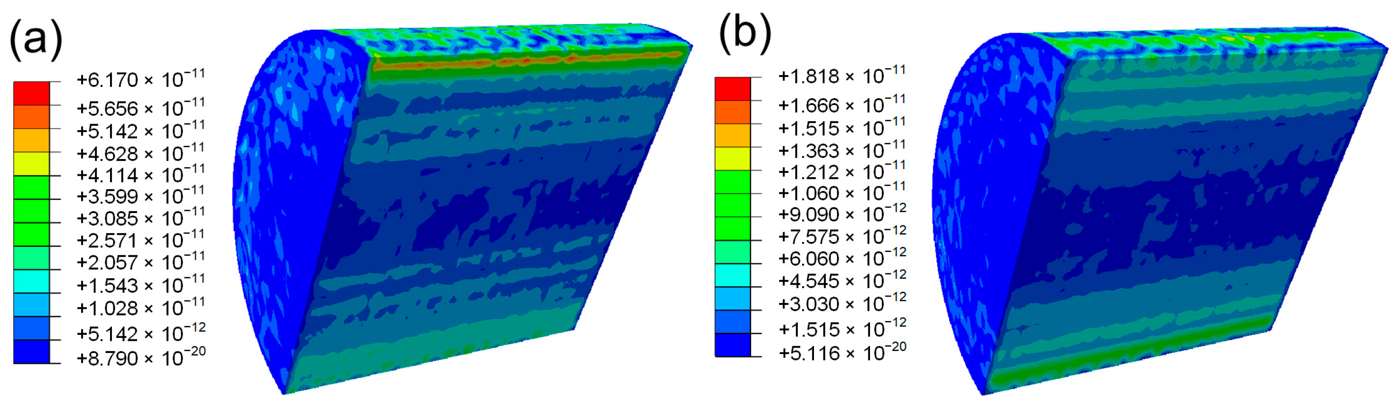
  • The increase in aluminum content led to a reduction in volume shrinkage during the cooling process at high temperatures. This reduction in shrinkage consequently lessened the thermal stress within the material, which was confirmed through finite element method (FEM) simulations. The lower thermal stress was directly linked to the prevention of solidification cracking.

Author Contributions

Conceptualization, H.Y., G.W. and L.L.; methodology, P.C.; software, L.L.; validation, H.Y., P.C., L.L. and M.L.; formal analysis, L.L. and P.C.; investigation, L.L. and M.L.; resources, H.Y.; data curation, P.C.; writing—original draft preparation, L.L.; writing—review and editing, P.C.; visualization, P.C.; supervision, P.C.; project administration, H.Y.; funding acquisition, G.W. All authors have read and agreed to the published version of the manuscript.

Funding

This work was supported by the Natural Science Foundation of Liaoning Province (grant number 2023-MSBA-037), and the Fundamental Research Funds for the Central University (grant number N2402007).

Data Availability Statement

The raw data supporting the conclusions of this article will be made available by the authors on request.

Conflicts of Interest

Author M.L. was employed by Fushun Special Steel Co., Ltd., and author H.Y. was employed by Easyforming Materials Technology Co., Ltd. The remaining authors declare that the research was conducted in the absence of any commercial or financial relationships that could be construed as a potential conflict of interest.

References

  1. Nong, X.D.; Xiong, X.J.; Gu, X.; Wang, L.; Jiang, Y.L.; Yu, L.; Rao, J.H.; Bi, Y.J. A novel low-cost ultra-strong maraging steel by additive manufacturing. Mater. Sci. Eng. A 2023, 887, 145747. [Google Scholar] [CrossRef]
  2. Brytan, Z.; Król, M.; Benedyk, M.; Pakieła, W.; Tomasz, T.; Dagnaw, M.J.; Snopiński, P.; Pagáč, M.; Czech, A. Microstructural and Mechanical Properties of Novel Co-Free Maraging Steel M789 Prepared by Additive Manufacturing. Materials 2022, 15, 1734. [Google Scholar] [CrossRef]
  3. Yang, X.C.; Li, C.N.; Han, J.Y.; Yang, Y.K.; Ju, Y.Z.; Ba, L.Z.; Wang, C.; Di, X.J. Effect of welding state on the re-precipitation behavior of Cu-rich and NiAl nanoparticles in HAZ of 1100 MPa grade low carbon ultra-high strength steel. Mater. Sci. Eng. A 2024, 897, 146334. [Google Scholar] [CrossRef]
  4. Jiang, Y.; Wu, X.H.L.X.X.; Liu, S.C.; Zhang, Y.; Chen, L.; Xu, S.S.; Liang, X.; Li, X.Z.; Zhang, Z.W. Microstructure and mechanical properties of a Cu/NiAl nanoprecipitate strengthened dual-phase steel. Mater. Charact. 2023, 196, 112594. [Google Scholar] [CrossRef]
  5. Yang, X.C.; Di, X.J.; Wang, J.S.; Fang, C.; Fu, W.; Ba, L.Z.; Zhou, X.F.; Zhang, C.Y.; Li, C.N. The co-precipitation evolution of NiAl and Cu nanoparticles and its influence on strengthening and toughening mechanisms in low-carbon ultra-high strength martensite seamless tube steel. Int. J. Plast. 2023, 166, 103654. [Google Scholar] [CrossRef]
  6. Zhou, B.C.; Yang, T.; Zhou, G.; Wang, H.; Luan, J.H.; Jiao, Z.B. Mechanisms for suppressing discontinuous precipitation and improving mechanical properties of NiAl-strengthened steels through nanoscale Cu partitioning. Acta Mater. 2021, 205, 116561. [Google Scholar] [CrossRef]
  7. Shen, Q.; Huang, D.Z.; Liu, W.Q.; Li, F.J.; Lu, Q. Effect of Cu content on the precipitation behavior of Cu-rich and NiAl phases in steel. Mater. Charact. 2022, 187, 111849. [Google Scholar] [CrossRef]
  8. Du, Y.B.; Hu, X.F.; Zhang, S.Q.; Song, Y.Y.; Jiang, H.C.; Rong, L.J. Precipitation behavior of Cu-NiAl nanoscale particles and their effect on mechanical properties in a high strength low alloy steel. Mater. Charact. 2022, 190, 112014. [Google Scholar] [CrossRef]
  9. Guo, L.L.; Zhang, L.N.; Andersson, J.; Ojo, O. Additive manufacturing of 18% nickel maraging steels: Defect, structure and mechanical properties: A review. Mater. Sci. Technol. 2022, 120, 227–252. [Google Scholar] [CrossRef]
  10. Kou, S. A criterion for cracking during solidification. Acta Mater. 2015, 88, 366–374. [Google Scholar] [CrossRef]
  11. Olson, G.B. Computational Design of Hierarchically Structured Materials. Science 1997, 277, 1237–1242. [Google Scholar] [CrossRef]
  12. Zhao, J.C. Combinatorial approaches as effective tools in the study of phase diagrams and composition–structure–property relationships. Prog. Mater. Sci. 2006, 51, 557–631. [Google Scholar] [CrossRef]
  13. Jiao, Z.B.; Luan, J.H.; Miller, M.K.; Liu, C.T. Precipitation mechanism and mechanical properties of an ultra-high strength steel hardened by nanoscale NiAl and Cu particles. Acta Mater. 2015, 97, 58–67. [Google Scholar] [CrossRef]
  14. Czyryca, E.J. Advances in high strength steel technology for naval hull construction. Key Eng. Mater. 1993, 84, 491–520. [Google Scholar] [CrossRef]
  15. Sahoo, G.; Singh, B.; Saxena, A. Effect of strain rate, soaking time and alloying elements on hot ductility and hot shortness of low alloy steels. Mater. Sci. Eng. A 2018, 718, 292–300. [Google Scholar] [CrossRef]
  16. Kondo, Y.; Tanei, H. Effect of Oxygen Concentration on Surface Hot Shortness of Steel Induced by Copper. ISIJ Int. 2015, 55, 1044–1047. [Google Scholar] [CrossRef]
  17. Hydrean, P.P.; Kitchin, A.L.; Schaller, F.W. Hot rolling and heat treatment of Ni−Cu−Cb(Nb) steel. Metall. Trans. 1971, 2, 2541–2548. [Google Scholar] [CrossRef]
  18. Mintz, B.; Abushosha, R.; Crowther, D.N. Influence of small additions of copper and niekel on hot ductility of steels. Mater. Sci. Technol. 2013, 11, 474–481. [Google Scholar] [CrossRef]
  19. Schäfer, L. Influence of delta ferrite and dendritic carbides on the impact and tensile properties of a martensitic chromium steel. J. Nucl. Mater. 1998, 258–263, 1336–1339. [Google Scholar] [CrossRef]
  20. Akram, J.; Kalvala, P.R.; Misra, M.; Charit, I. Creep behavior of dissimilar metal weld joints between P91 and AISI 304. Mater. Sci. Eng. A 2017, 688, 396–406. [Google Scholar] [CrossRef]
  21. Chen, S.P.; Rana, R.; Haldar, A.; Ray, R.K. Current state of Fe-Mn-Al-C low density steels. Prog. Mater. Sci. 2017, 89, 345–391. [Google Scholar] [CrossRef]
  22. Yang, X.C.; Di, X.J.; Duan, Q.Y.; Fu, W.; Ba, L.Z.; Li, C.N. Effect of precipitation evolution of NiAl and Cu nanoparticles on strengthening mechanism of low carbon ultra-high strength seamless tube steel. Mater. Sci. Eng. A 2023, 872, 144939. [Google Scholar] [CrossRef]
  23. Niu, M.C.; Yang, K.; Luan, J.H.; Wang, W.; Jiao, Z.B. Cu-assisted austenite reversion and enhanced TRIP effect in maraging stainless steels. J. Mater. Sci. Technol. 2022, 104, 52–58. [Google Scholar] [CrossRef]
  24. Sha, W.; Leitner, H.; Guo, Z.; Xu, W. Phase transformations in maraging steels. In Phase Transformations in Steels; Pereloma, E., Edmonds, D.V., Eds.; Woodhead Publishing Limited: Cambridge, UK, 2012; pp. 332–362. [Google Scholar]
Figure 1. Cu phase at 1000 °C and 1050 °C.
Metals 14 01020 g001
Figure 2. Calculated δ ferrite phase fractions as a function of alloying addition and temperature at 900 °C.
Metals 14 01020 g002
Figure 3. Pseudo-binary phase diagram of Fe-0.05C-0.5Mo-0.02Nb-5Cu-2.5Ni-2Al.
Metals 14 01020 g003
Figure 4. The cast ingot of 1.0Al (a) and 1.2Al (b); the microstructure of 1.0Al (c) and 1.2Al (d); (e) the crack observation. The blue arrows pointed to the macroscopic crack, the red rectangle and yellow arrow represented locally enlarged macroscopic cracks; (f) the distribution of elements near the crack surface.
Metals 14 01020 g004aMetals 14 01020 g004b
Figure 5. (a) The phase fraction as a function of temperature; (b,c) DSC curves during cooling; (d) the thermal expansivity of the system as a function of temperature; (e) the variation in density of the system with temperature.
Metals 14 01020 g005
Figure 6. The thermal stress distribution analysis of 1.0Al (a) and 1.2Al (b) by FEM.
Metals 14 01020 g006
Figure 7. The typical tensile curves of 1.0Al and 1.2Al steels.
Metals 14 01020 g007
Disclaimer/Publisher’s Note: The statements, opinions and data contained in all publications are solely those of the individual author(s) and contributor(s) and not of MDPI and/or the editor(s). MDPI and/or the editor(s) disclaim responsibility for any injury to people or property resulting from any ideas, methods, instructions or products referred to in the content.

