
Realization of Friction Stir Welding of Aluminum Alloy AA5754 Using a Ceramic Tool


Abstract
:1. Introduction
2. Materials and Methods
3. Results and Discussion
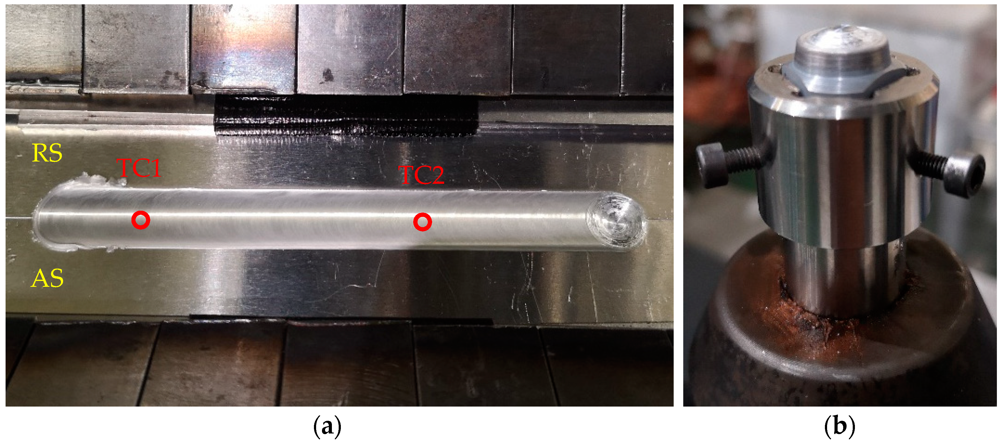
3.1. Process
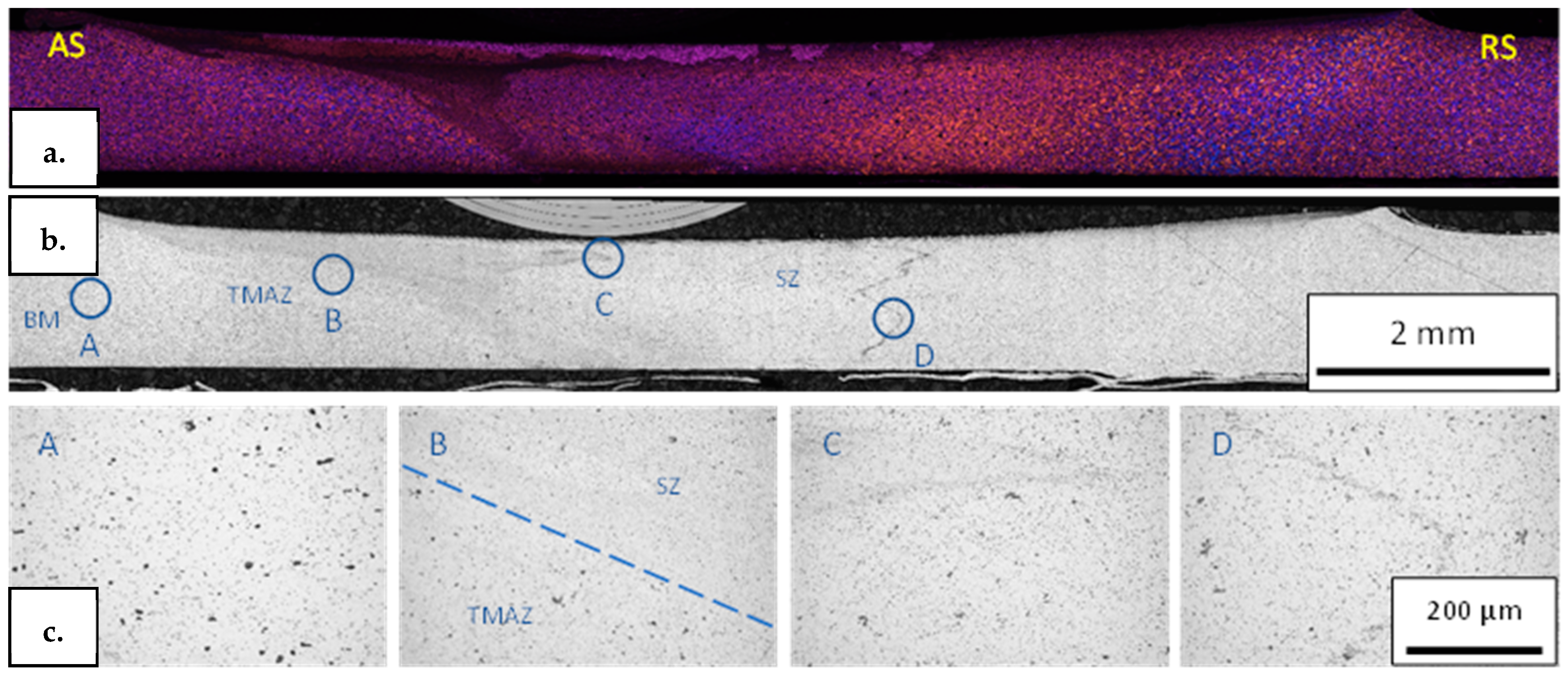
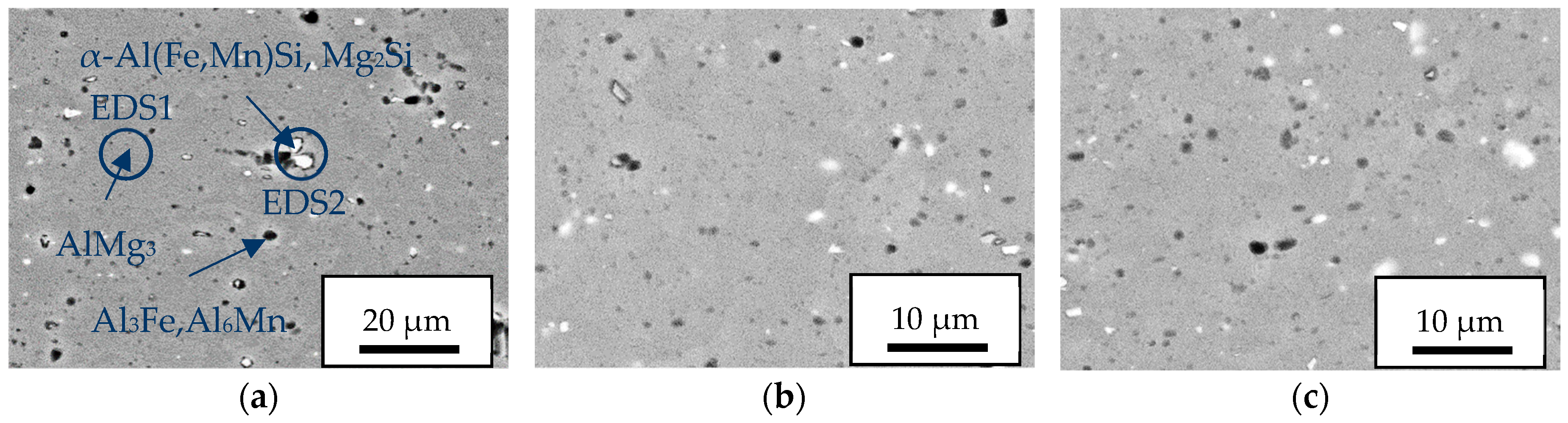
3.2. Microstructure
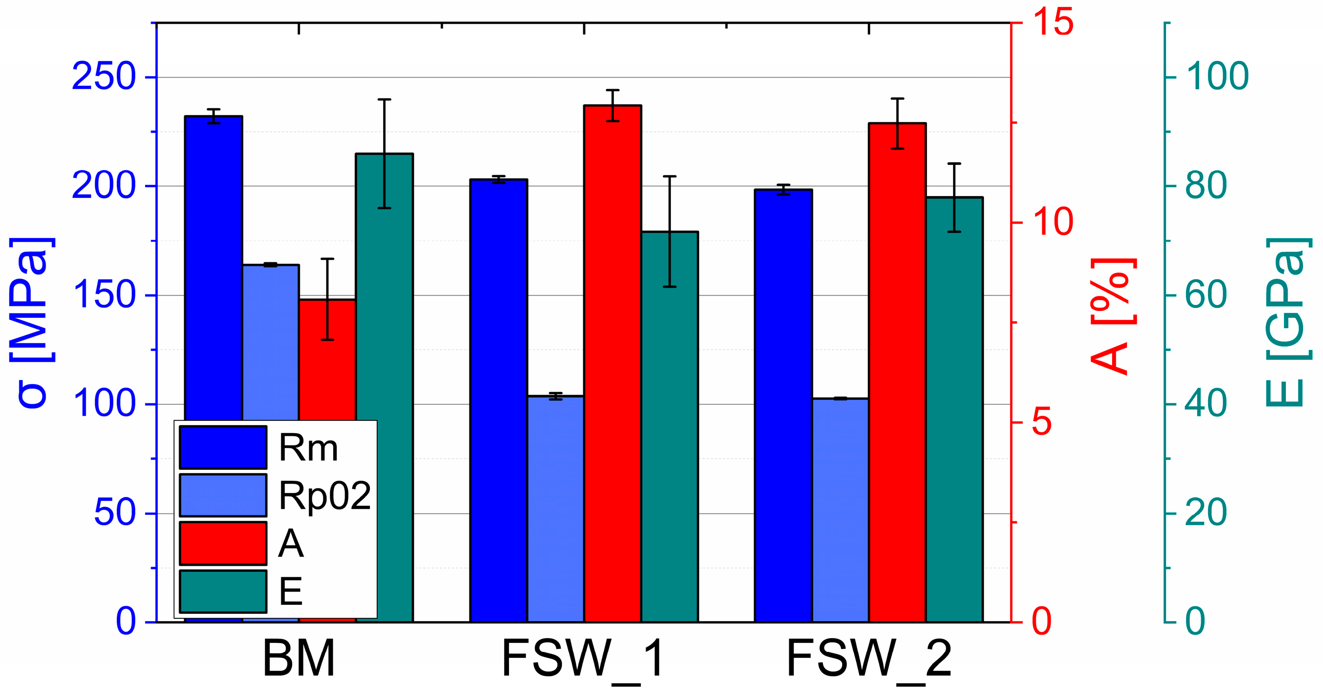
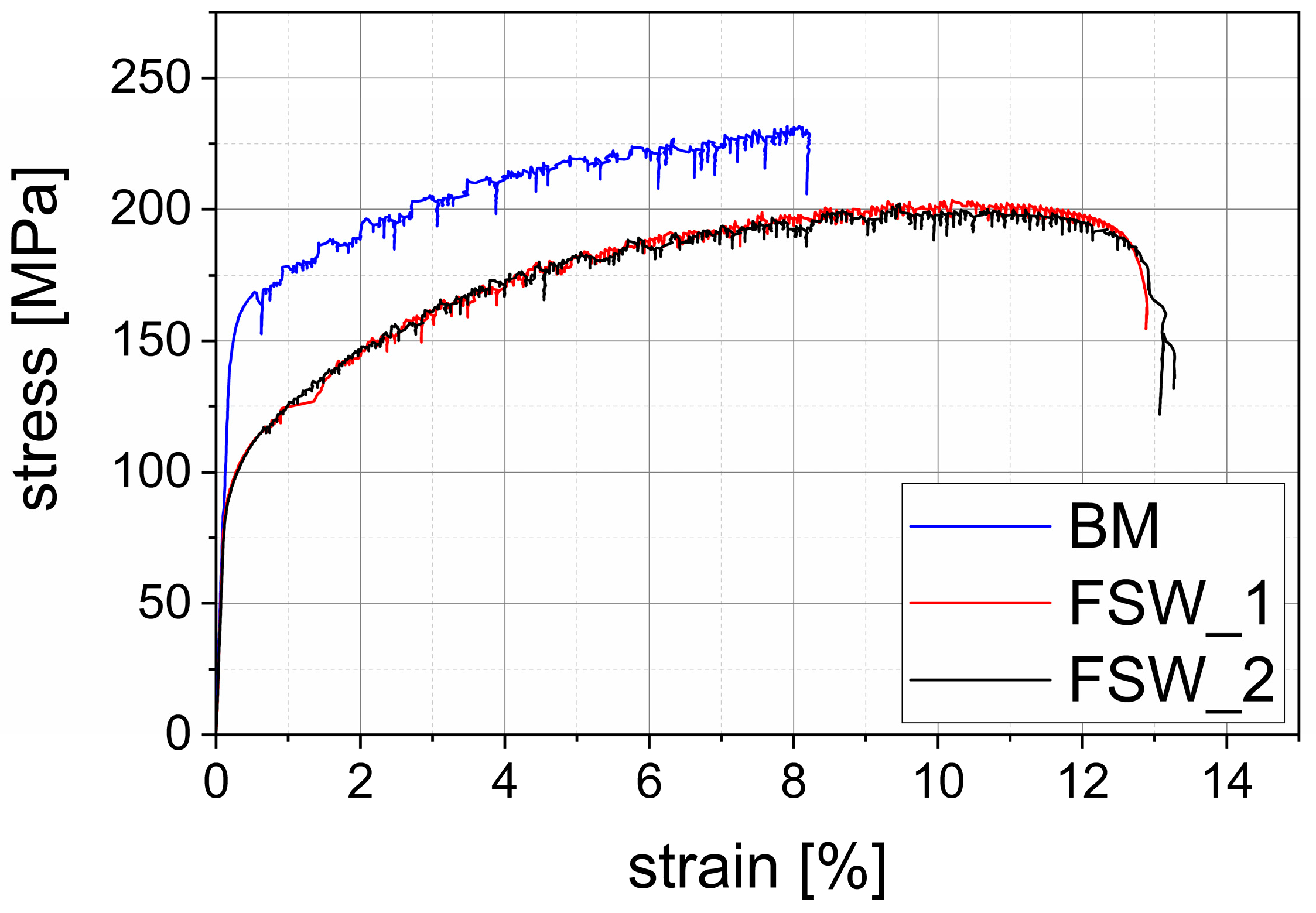
3.3. Mechanical Properties
4. Conclusions
- It is possible to weld 1.25 mm thick sheets of AA5754 by using a ceramic FSW tool made of Si3N4. No wear or even fractures of the tool occurred during welding at a vertical force of 2500 N and temperatures of at least 400 °C.
- The formation of solid joints with an ultimate tensile strength of 88% relative to the base material was successfully achieved.
- The microstructure of the FSW joint is identical to that of conventional tools, including characteristic zones, grain refinement, and grain distribution. Additionally, no ceramic particles of the tool could be found in the welded seam.
- The SEM images demonstrate a refinement and more homogeneous distribution of the precipitates in TMAZ and SZ as a result of the FSW process.
- In contrast to the BM, the PLC is affected by the FSW process. The range between force peaks exhibited a reduction.
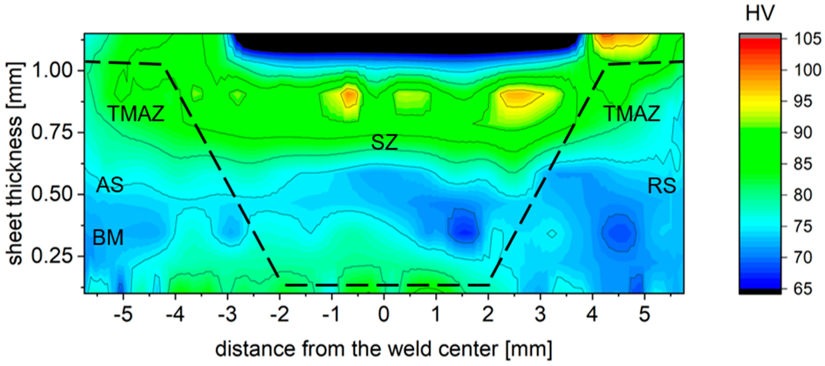
- The grain refinement of the TMAZ and SZ resulted in an increase in the hardness, especially on the upper SZ.
Author Contributions
Funding
Data Availability Statement
Conflicts of Interest
References
- Ahmed, M.M.Z.; El-Sayed Seleman, M.M.; Fydrych, D.; Çam, G. Friction Stir Welding of Aluminum in the Aerospace Industry: The Current Progress and State-of-the-Art Review. Materials 2023, 16, 2971. [Google Scholar] [CrossRef] [PubMed]
- Wang, G.; Zhao, Y.; Hao, Y. Friction stir welding of high-strength aerospace aluminum alloy and application in rocket tank manufacturing. J. Mater. Sci. Technol. 2018, 34, 73–91. [Google Scholar] [CrossRef]
- Kavathia, K.; Badheka, V. Application of Friction Stir Welding (FSW) in Automotive and Electric Vehicle. In Recent Advances in Mechanical Infrastructure; Springer: Berlin/Heidelberg, Germany, 2022; pp. 289–304. [Google Scholar] [CrossRef]
- Chyła, K.; Gaska, K.; Gronba-Chyła, A.; Generowicz, A.; Grąz, K.; Ciuła, J. Advanced Analytical Methods of the Analysis of Friction Stir Welding Process (FSW) of Aluminum Sheets Used in the Automotive Industry. Materials 2023, 16, 5116. [Google Scholar] [CrossRef]
- Paik, J.K. Mechanical properties of friction stir welded aluminum alloys 5083 and 5383. Int. J. Nav. Archit. Ocean Eng. 2009, 1, 39–49. [Google Scholar] [CrossRef]
- Barlas, Z.; Ozsarac, U. Effects of FSW Parameters on Joint Properties of AlMg3 Alloy. Weld. J. 2012, 91, 16–22. [Google Scholar]
- Ahmed, M.M.Z.; Essa, A.R.S.; Ataya, S.; El-Sayed Seleman, M.M.; El-Aty, A.A.; Alzahrani, B.; Touileb, K.; Bakkar, A.; Ponnore, J.J.; Mohamed, A.Y.A. Friction Stir Welding of AA5754-H24: Impact of Tool Pin Eccentricity and Welding Speed on Grain Structure, Crystallographic Texture, and Mechanical Properties. Materials 2023, 16, 2031. [Google Scholar] [CrossRef]
- De Filippis, L.; Serio, L.; Palumbo, D.; de Finis, R.; Galietti, U. Optimization and Characterization of the Friction Stir Welded Sheets of AA 5754-H111: Monitoring of the Quality of Joints with Thermographic Techniques. Materials 2017, 10, 1165. [Google Scholar] [CrossRef]
- Vairis, A.; Petousis, M.; Mountakis, N.; Tsarouchidou, C.; Vidakis, N. The Effect of Tool Geometry on the Strength of FSW Aluminum Thin Sheets. Materials 2022, 15, 8187. [Google Scholar] [CrossRef]
- Wu, C.; Wang, J.; Wang, Q.; Xia, P.; Li, D. 7075 aluminum alloy Friction Stir Welding (FSW): Quality analysis and mechanical properties with WC-Co tool. Mater. Today Commun. 2024, 38, 108203. [Google Scholar] [CrossRef]
- Long, L.; Zhang, X.; Gu, S.; Li, X.; Cheng, X.; Chen, G. Experimental and Simulation Investigation on Fatigue Performance of H13 Steel Tools in Friction Stir Welding of Aluminum Alloys. Materials 2024, 17, 1535. [Google Scholar] [CrossRef]
- Kolnes, M.; Kübarsepp, J.; Sergejev, F.; Kolnes, M.; Tarraste, M.; Viljus, M. Performance of Ceramic-Metal Composites as Potential Tool Materials for Friction Stir Welding of Aluminium, Copper and Stainless Steel. Materials 2020, 13, 1994. [Google Scholar] [CrossRef]
- Mysliwiec, P.; Śliwa, R.E. Friction Stir Welding of Thin Sheets of the AA2024-T3 Alloy with a Ceramic Tool: RSM and ANOVA Study. Key Eng. Mater. 2022, 926, 1756–1761. [Google Scholar] [CrossRef]
- Buszta, S.; Myśliwiec, P.; Śliwa, R.E.; Ostrowski, R. The Influence of Geometrical Parameters and Tools Material on the Quality of the Joint Made by FSW Method in AA2024 Thin Sheets. Arch. Metall. Mater. 2019, 64, 805–812. [Google Scholar] [CrossRef]
- Emmel, M.; Karbaum, J.; Ziwck, M.; Boywitt, R. Development and Evaluation of Alternative Materials for Friction Stir Welding of Steel. Ceram. Appl. 2020, 8, 38–43. [Google Scholar]
- Zifčák, P.; Blažíček, P.; Pastier, P. The effect of selected welding parameters on properties of FSW welded joints in ferritic steel type S235 JRC+N. Weld. Technol. Rev. 2014, 86, 73–81. [Google Scholar]
- Funaki, K.; Morisada, Y.; Hasegawa, K.; Fukasawa, T.; Abe, Y.; Fujii, H. Elucidation of tool wear phenomenon in FSW using silicon nitride tool. Weld. Int. 2024, 38, 500–510. [Google Scholar] [CrossRef]
- Ahn, B.W.; Choi, D.H.; Kim, D.J.; Jung, S.B. Microstructures and properties of friction stir welded 409L stainless steel using a Si3N4 tool. Mater. Sci. Eng. A 2012, 532, 476–479. [Google Scholar] [CrossRef]
- DIN Deutsches Institut für Normung e. V. Metallische Werkstoffe–Zugversuch–Teil 1: Prüfverfahren bei Raumtemperatur (ISO 6892-1:2019); Metallic Materials–, 2020 (6892-1). Available online: https://www.din.de/de/wdc-beuth:din21:317931281 (accessed on 10 September 2024).
- QSIL Ceramics GmbH. FCT Si3N4 Sonderwerkstoffe. 2019. Available online: https://www.qsil-ceramics.com/fileadmin/user_upload/downloads/Datenbl%C3%A4tter/FCTSi3N4-Sonderwerkstoffe2019_10de.pdf (accessed on 15 October 2019).
- QSIL Ceramics GmbH. Material Data Sheet for Gas Pressure Sintered Silicon Nitride; QSIL Ceramics GmbH: Auma-Weidatal, Germany, 2020; Available online: https://www.qsil-ceramics.com/fileadmin/user_upload/downloads/Datenbl%C3%A4tter/SN-GP_De.pdf (accessed on 23 October 2019).
- ISO 4957:2018; DIN-Normenausschuss Eisen und Stahl. Tool Steels. German version EN ISO 4957:2018. Beuth Verlag: Berlin, Germany, 2018.
- Datasheet; HSM Stahl- und Metallhandel GmbH. 1.2344 Datenblatt. 2024. Available online: https://www.hsm-stahl.de/werkstoff/12344/ (accessed on 10 September 2024).
- Ghetiya, N.D.; Patel, K.M. Numerical simulation on an effect of backing plates on joint temperature and weld quality in air and immersed FSW of AA2014-T6. Int. J. Adv. Manuf. Technol. 2018, 99, 1937–1951. [Google Scholar] [CrossRef]
- Sprigode, T.; Gester, A.; Wagner, G.; Brückner-Foit, A.; Boudhraa, B.; Rienäcker, A. Improving weld quality with optimized bobbin tools: An innovative approach to friction stir welding of aluminium. In Proceedings of the 60th Ilmenau Scientific Colloquium Technische Universität Ilmenau, Ilmenau, Germany, 4–8 September 2023. [Google Scholar] [CrossRef]
- El Rayes, M.M.; Soliman, M.S.; Abbas, A.T.; Pimenov, D.Y.; Erdakov, I.N.; Abdel-mawla, M.M. Effect of Feed Rate in FSW on the Mechanical and Microstructural Properties of AA5754 Joints. Adv. Mater. Sci. Eng. 2019, 2019, 4156176. [Google Scholar] [CrossRef]
- Kanaya, K.; Okayama, S. Penetration and energy-loss theory of electrons in solid targets. J. Phys. D Appl. Phys. 1972, 5, 43. [Google Scholar] [CrossRef]
- Engler, O.; Kuhnke, K.; Hasenclever, J. Development of intermetallic particles during solidification and homogenization of two AA 5xxx series Al-Mg alloys with different Mg contents. J. Alloys Compd. 2017, 728, 669–681. [Google Scholar] [CrossRef]
- Facts—Datenbank für Werkstoffe und Normen. EN AW-5754 Datenblatt: Eigenschaften, Anwendungsgebiete, Besonderheiten. Available online: https://facts.kloeckner.de/werkstoffe/aluminium/3-3535/ (accessed on 10 September 2024).
- Halim, H.; Wilkinson, D.S.; Niewczas, M. The Portevin–Le Chatelier (PLC) effect and shear band formation in an AA5754 alloy. Acta Mater. 2007, 55, 4151–4160. [Google Scholar] [CrossRef]
- Woo, W.; Ungár, T.; Feng, Z.; Kenik, E.; Clausen, B. X-Ray and Neutron Diffraction Measurements of Dislocation Density and Subgrain Size in a Friction-Stir-Welded Aluminum Alloy. Met. Mater. Trans. A 2010, 41, 1210–1216. [Google Scholar] [CrossRef]
- Pathak, N.; Bandyopadhyay, K.; Sarangi, M.; Panda, S.K. Microstructure and Mechanical Performance of Friction Stir Spot-Welded Aluminum-5754 Sheets. J. Mater. Eng. Perform. 2013, 22, 131–144. [Google Scholar] [CrossRef]


| Material | Elements | Rp0.2 | Rm | ||||||||
|---|---|---|---|---|---|---|---|---|---|---|---|
| wt.% | MPa | MPa | |||||||||
| AA5754 | Si | Fe | Cu | Mn | Mg | Cr | Zn | Ti | Al | 164 | 232 |
| 0.4 | 0.4 | 0.1 | 0.5 | 2.6–3.6 | 0.3 | 0.2 | 0.15 | Bal. | |||
| Property | SN-PU | SN-GP | H13 |
|---|---|---|---|
| composition | 97 wt.% Si3N4 bal. RE2O3/Al2O3 | 85–92 wt.% Si3N4 bal. RE2O3/Al2O3 | DIN EN ISO 4957 |
| bulk density [g/cm3] | 3.18–3.22 | 3.18–3.30 | 7.74 |
| residual porosity [%] | 0.5 | < 1 | - |
| including open porosity [%] | 0 | 0 | - |
| hardness [GPa] | 15.3 | 14.5 | 1.7 (50 HRC) |
| Young’s modulus [GPa] | 310–320 | 290 | 210 |
| strength [MPa] | 3000 (compressive) | 3000 (compressive) | 1800 (tensile) |
| thermal expansion coefficient [K−1] | 1.2 × 10⁻⁶ | 1.4 × 10⁻⁶ | 10.8 × 10⁻⁶ |
| Method | Element [wt.%] | ||||
|---|---|---|---|---|---|
| Mg | Al | Si | Mn | Fe | |
| EDS1 | 3.49 | 96.51 | - | - | - |
| EDS2 | 2.68 | 80,66 | 2.84 | 2.79 | 11.04 |
| element [µm] | |||||
| Mg | Al | Si | Mn | Fe | |
| Kanaya–Okayama range | 9.15 | 6.09 | 6.85 | 2.52 | 2.34 |
Disclaimer/Publisher’s Note: The statements, opinions and data contained in all publications are solely those of the individual author(s) and contributor(s) and not of MDPI and/or the editor(s). MDPI and/or the editor(s) disclaim responsibility for any injury to people or property resulting from any ideas, methods, instructions or products referred to in the content. |
© 2024 by the authors. Licensee MDPI, Basel, Switzerland. This article is an open access article distributed under the terms and conditions of the Creative Commons Attribution (CC BY) license (https://creativecommons.org/licenses/by/4.0/).
Share and Cite
Sprigode, T.; Gester, A.; Wagner, G.; Degenhardt, U. Realization of Friction Stir Welding of Aluminum Alloy AA5754 Using a Ceramic Tool. Metals 2024, 14, 1089. https://doi.org/10.3390/met14091089
Sprigode T, Gester A, Wagner G, Degenhardt U. Realization of Friction Stir Welding of Aluminum Alloy AA5754 Using a Ceramic Tool. Metals. 2024; 14(9):1089. https://doi.org/10.3390/met14091089
Chicago/Turabian StyleSprigode, Toni, Andreas Gester, Guntram Wagner, and Ulrich Degenhardt. 2024. "Realization of Friction Stir Welding of Aluminum Alloy AA5754 Using a Ceramic Tool" Metals 14, no. 9: 1089. https://doi.org/10.3390/met14091089
APA StyleSprigode, T., Gester, A., Wagner, G., & Degenhardt, U. (2024). Realization of Friction Stir Welding of Aluminum Alloy AA5754 Using a Ceramic Tool. Metals, 14(9), 1089. https://doi.org/10.3390/met14091089