Article

Reduction of Elongation Anisotropy of Roll-Cast Strips by Cold Rolling and Annealing

Department of Mechanical Engineering, School of Engineering, Osaka Institute of Technology, Osaka 535-8585, Japan
Metals 2024, 14(9), 965; https://doi.org/10.3390/met14090965
Submission received: 17 July 2024 / Revised: 24 August 2024 / Accepted: 24 August 2024 / Published: 26 August 2024
(This article belongs to the Special Issue Advances in Metal Rolling Processes)

Abstract

:
Roll-cast strips are usually cold-rolled and annealed before forming. The elongation of these strips is known to be different between the casting and lateral directions after thinning by cold rolling. Whether cold rolling is the main factor determining the anisotropy of the elongation is not clear. Likewise, it is not clear whether the elongation anisotropy can be reduced by conventional cold rolling. Roll-cast strips have centerline segregation, forming a so-called band area. The relationship between the anisotropy of the elongation and these defects is not clear. A strip cast using an unequal-diameter twin-roll caster also has a band area but a strip cast using a single-roll caster equipped with a scraper has no centerline segregation or band area. Strips made this way were cold-rolled in the casting and lateral directions, and tensile testing was conducted on the cold-rolled and annealed strips. In this study, the ability of conventional cold rolling and one-time annealing to reduce the elongation anisotropy of a cast strip was clarified. Moreover, the influence of the band area and Fe impurities on the elongation anisotropy was determined.

Graphical Abstract

1. Introduction

A conventional twin-roll caster for aluminum alloy (CTRCA) [1,2,3,4,5,6,7,8,9,10,11] has the advantages of rapid processing and energy saving compared to direct chill casting [12,13] and hot rolling for making aluminum alloy strips. The CTRCA also has disadvantages, namely low productivity. The cause of the low productivity is its typical slow casting speed of 1 m/min. A high-speed twin-roll caster (HSTRC) [14,15,16,17] has been developed to improve the low casting speed. Further, an unequal-diameter twin-roll caster (UDTRC) [18,19], one type of HSTRC, can cast aluminum alloy strips at speeds from 10 to 60 m/min. After casting, the strip is cold-rolled to give it the specified thickness. The elongation along the casting and lateral directions is usually not the same in strips cast using the CTRCA [20] after cold rolling and annealing. Aluminum alloy strips cast using the UDTRC also have elongation anisotropy after cold rolling and annealing.
There are many studies concerning the improvement of the mechanical properties and reduction of their anisotropy in cold-rolled and annealed roll-cast aluminum alloy strips. They have looked at the effects of thickness reduction by rolling on surface defects and strain formed in the thickness direction [21]; hot rolling on the mechanical properties [22]; the relationship between factors of the forming process on the mechanical properties [23]; homogenization before cold rolling on the microstructure and mechanical properties [24,25,26,27]; the relationship between cold rolling reduction and shape of eutectic Si elongation anisotropy [28]; improvement of mechanical properties by the combination of hot rolling, cold rolling, hominization, and annealing [29]; controlling the shear texture by asymmetric rolling [30]; and improving mechanical properties and reducing the anisotropy by combining hot rolling, asymmetric cold rolling, and several heat treatment durations [31].
In these studies, heat treatment was conducted more than two times. Hot rolling needs heating equipment, and asymmetric rolling needs a special mill. Cold rolling was conducted after hot and asymmetric rolling. Thus, more than two types of mills are needed.
To reduce the process cost, conventional cold rolling and one-time heat treatment (annealing) after cold rolling are suitable. This study mainly investigated the ability of conventional cold rolling and one-time heat treatment to reduce the elongation anisotropy of a cold-rolled and annealed roll-cast strip. A single-roll caster equipped with a scraper (SRCS) [32] was used. A strip cast using the SRCS is free from the center segregation and band area formed by the twin-roll casters, and the influence of these defects can be excluded.
The microstructure of a strip cast using the CTRCA and UDTRC is not uniform in the thickness direction. Strips cast using the UDTRC have a band area [33,34] between the solidified layers cast by the twin rolls. The effect of the band area on the anisotropy of the elongation is not clear. Thus, the second aim of this study was to clarify the influence of the band area on the elongation anisotropy by comparing strips with this band area to strips without this band area. To achieve this, both the SRCS and UDTRC were used.
In a vehicle, the outer panels are made from Al–Mg–Si, such as 6016 alloy, and the inner panels are made from Al–Mg, such as 5182 alloy. In this study, the JIS AC7A alloy (similar to 5182) [35] was used as the Al–Mg alloy. When the aluminum alloy parts of a vehicle are recycled, the Fe content in the alloy increases. Because the effect of increased Fe impurity content on the anisotropy of elongation is not clear, our third aim was to clarify the influence of increased Fe content on the elongation anisotropy.

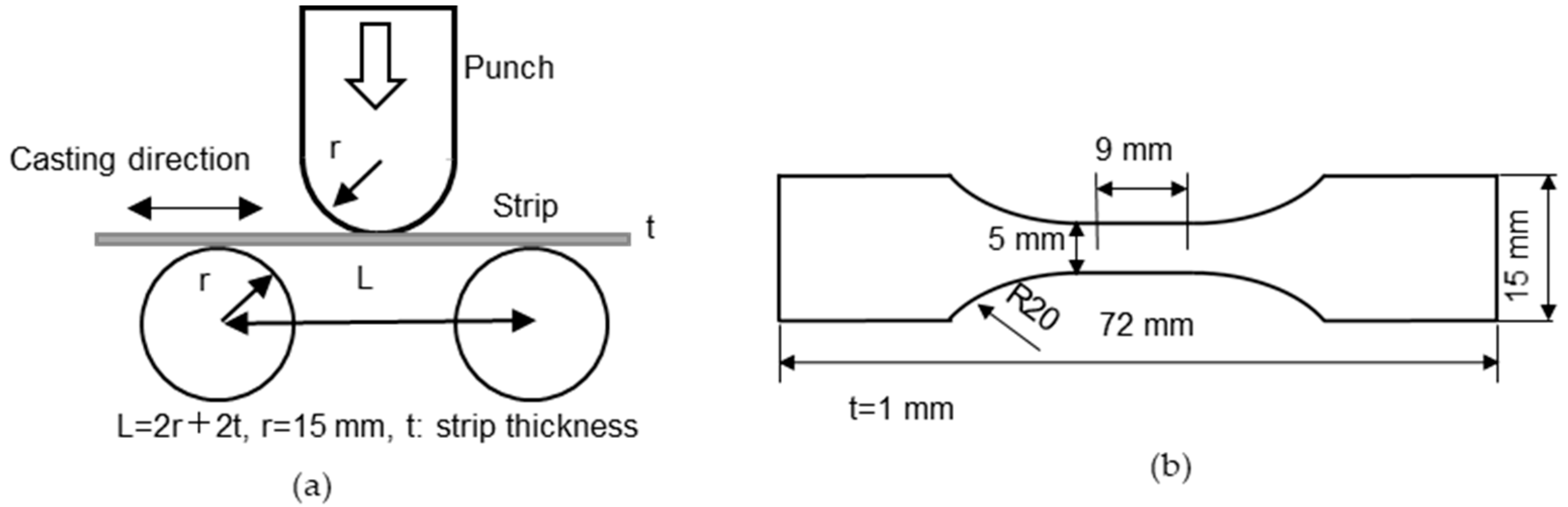
2. Experimental Methods

Schematic diagrams of the UDTRC and SRCS are shown in Figure 1a and Figure 1b, respectively; an enlarged view of the SRCS scraper is shown in Figure 1c. The rolls were made of copper in both the UDTRC and SRCS. In the UDTRC, the diameters of the upper and lower rolls were 300 and 1000 mm, respectively, and the width of both rolls was 100 mm. The unit roll load was 2.3 N/mm, and the initial gap between rolls was 1 mm.
In the SRCS, the roll diameter and width were 1000 mm and 100 mm, respectively. The unit scraper load was 0.12 N/mm. The scraper could rotate around a pivot depending on the solidified layer thickness. The initial gaps between the scraper and the roll surface and between rolls were 1 mm. In both the UDRTC and SRCS, the solidification length was 200 mm, and the roll speed was 30 m/min. The roll was rotated at the designated speed, and then the molten metal was poured.
JIS AC7A and AC7A + X%Fe (X = 0.2, 0.4, 0.6, and 0.8%) alloys were used. The Fe-added AC7A specimens were cast with the SRCS as models for recycled AC7A. The chemical compositions of the AC7A and Fe-added AC7A are shown in Table 1. The pouring temperature of the molten metal was 670 °C.
The AC7A and the AC7A + 0.8%Fe were cast using the UDTRC and SRCS, respectively. Bending tests were conducted on the as-cast strips to investigate surface cracking. A schematic diagram of the bending test is shown in Figure 2. The bending direction was normal to the casting direction. As-cast strips were used for the bending test. A punch was pushed 30 mm (2r) from the position where it contacted the strip. When the strip broke, the punch was stopped. The cast strips were cold-rolled down to 0.5, 0.7, and 1.0 mm. The cold rolling directions were the casting direction and the lateral direction. Tensile tests were conducted in the cold rolling direction and the direction normal to the cold rolling direction. The gage length and width of the test piece for tensile testing were 9 and 5 mm, respectively. The cold-rolled strip was annealed at 360 °C for 90 min before the tensile testing. The purpose of this post-deformation annealing is to recrystallize the materials. Tensile testing was performed in both the casting and lateral directions using the universal testing machine (AG-I/100 kN, SIMADZU, Nakagyo-ku, Kyoto, Japan). The length of the cast strip was approximately 5 m, and the test pieces were taken from the central 3 m section. Seven specimens were tested and five data points, excluding the maximum and minimum values, were used for each condition in the tensile testing. Etching was performed using 1% hydrofluoric acid for 20 s. The cross sections of strips were observed using optical microscopy.

3. Results and Discussion

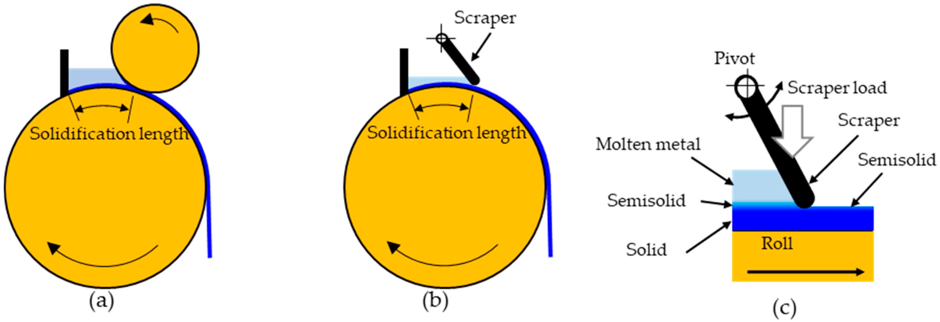
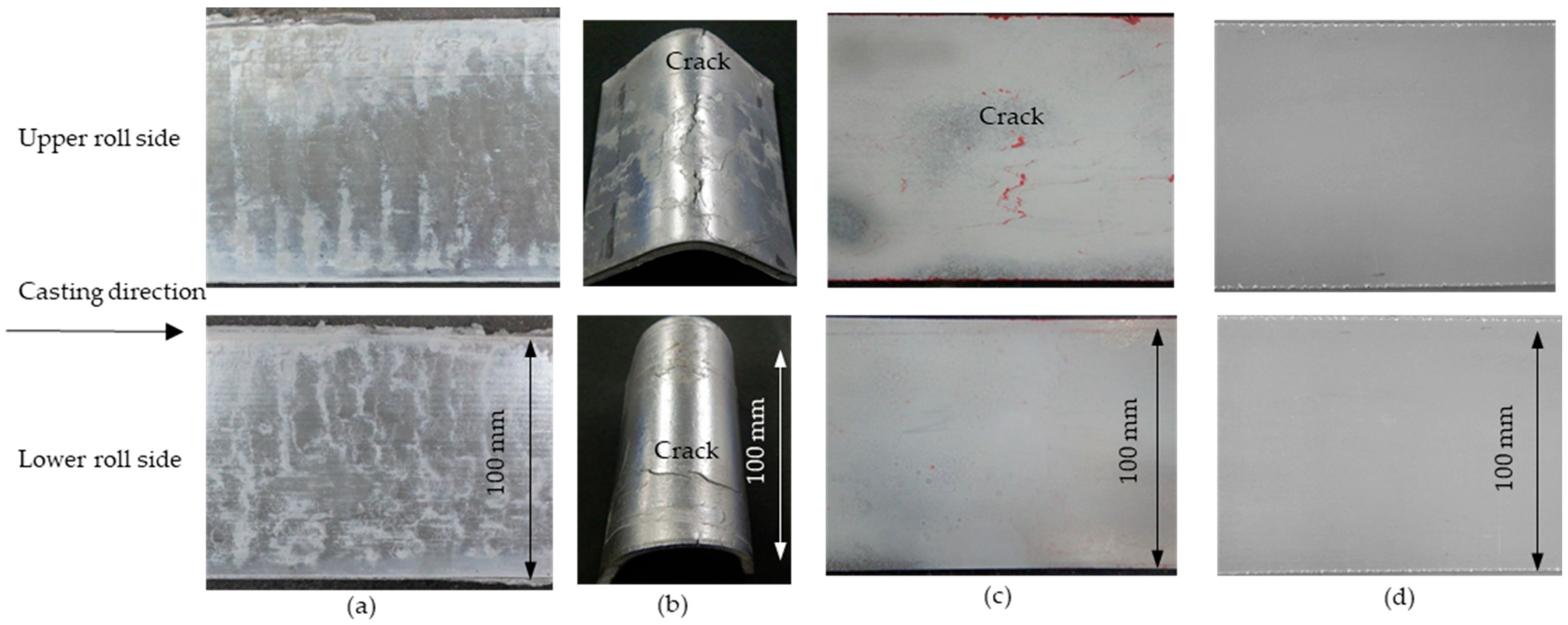
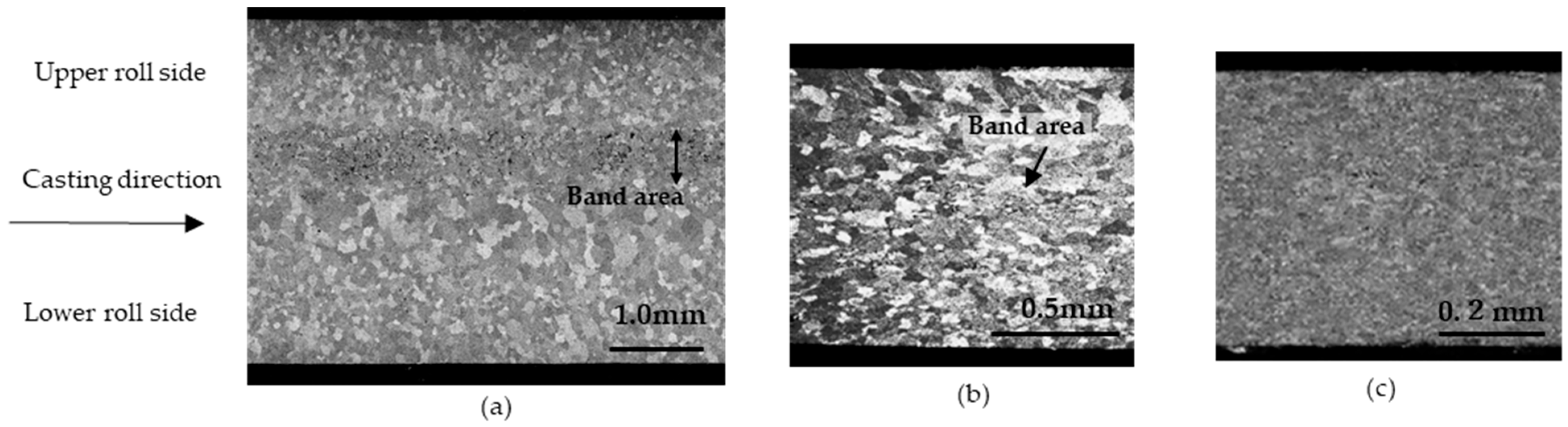
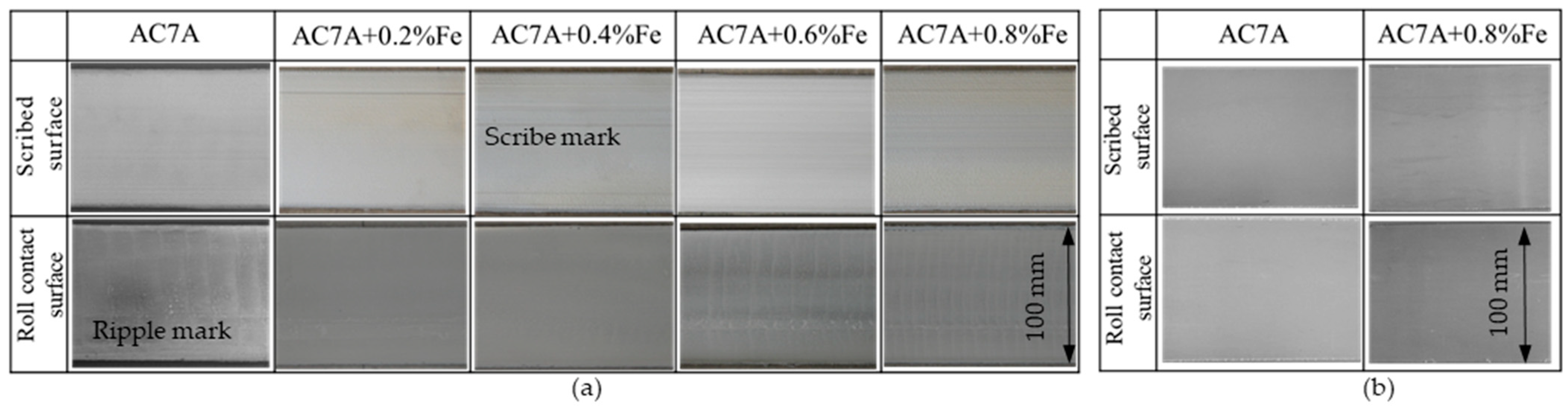
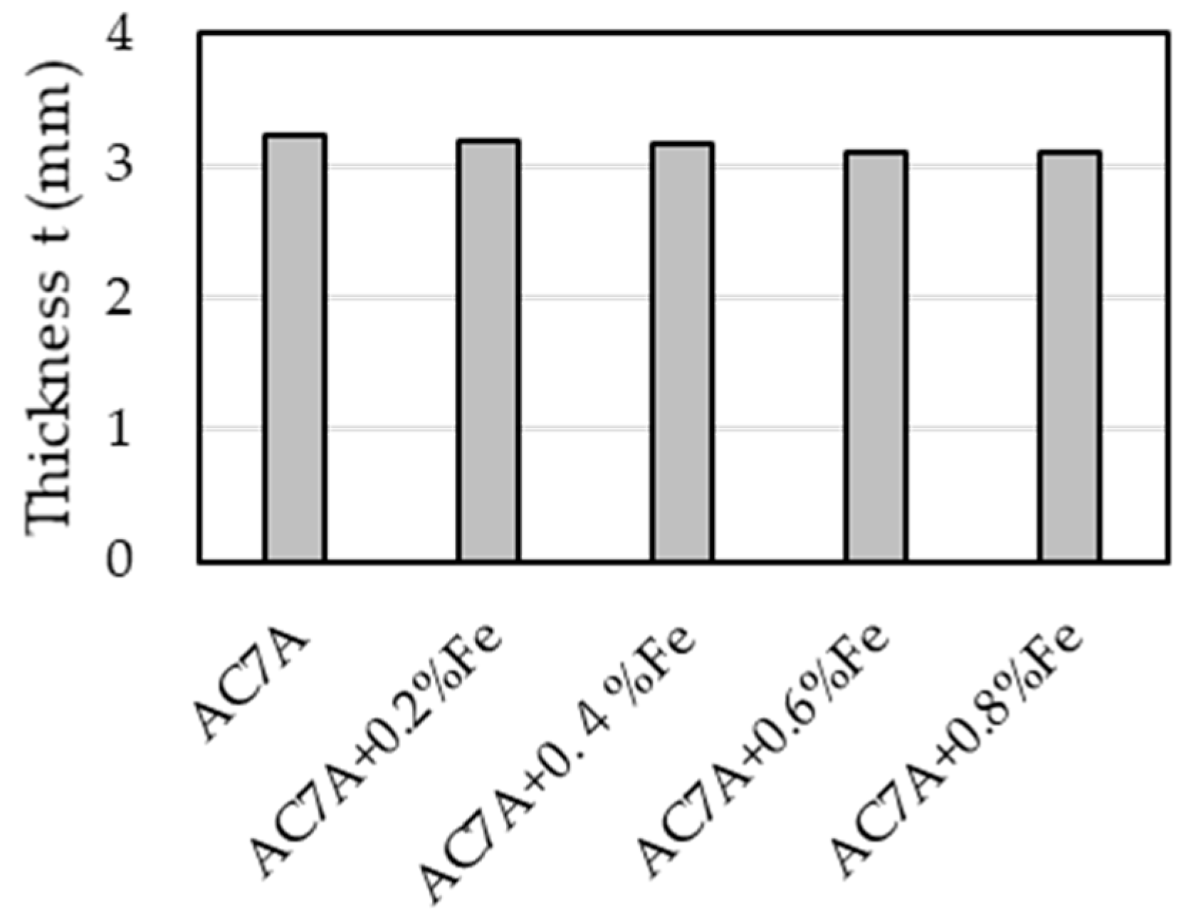
3.1. Cast Strip Using a UDTRC

The surfaces of as-cast strips, bending tests of the as-cast strips, and penetrant tests of cold-rolled strips cast using the UDTRC are shown in Figure 3. Ripple marks were present on the upper and lower surfaces of the as-cast strips, as shown in Figure 3a. Cracks were formed on the upper and lower surfaces by the bending tests, as shown in Figure 3b. When the upper surface was on the outer side, the as-cast strip was broken as a result of such cracking. The crack directions and sizes were random. The position of some cracks corresponded to the position of the ripple marks. The cracks looked like they were present on the as-cast strip but were not caused by bending. The results of penetrant tests on strips cold-rolled down to 1 mm and 0.5 mm are shown in Figure 3c and Figure 3d, respectively. The thickness of the as-cast strips was 3.7 mm, and the thickness reductions to reach 1 mm and 0.5 mm were 74% and 86%, respectively. When the thickness of a cold-rolled strip was 1 mm, cracking was reduced but still was present. When the cold-rolled strip thickness reached 0.5 mm, the cracks disappeared. In other words, cracks can be removed by cold rolling.
The cross sections of an as-cast strip and strips cold-rolled down to 1 mm and 0.5 mm and annealed at 360 °C for 90 min are shown in Figure 4. The band area was present on the as-cast strip, as shown in Figure 4a. The crushed band area can be seen on the 1 mm cold-rolled strip, as shown in Figure 4b. This band area is not seen in the cross section of the 0.5 mm cold-rolled strip (thickness reduction of 86%), and the grains in this strip became smaller than those in the 1 mm cold-rolled strip, as shown in Figure 4c. Clearly, the surface cracking and band area can be removed when the thickness reduction due to cold rolling is at least 86%.
Results of tensile testing of strips cold-rolled down to 1 mm and 0.5 mm and annealed are shown in Figure 5. In the 1 mm-thick strip, the test pieces were made from the areas where cracks were not present. The rolling direction was the casting direction. When the strip thickness was 1 mm (reduction of 74%), the elongation in the lateral direction was 7% smaller than that in the casting direction. When the strip thickness was 0.5 mm (reduction of 86%), the difference in the elongation between the casting and lateral directions was 1% and smaller than that of the 1 mm-thick strip. The elongation in the casting and lateral directions was almost the same when the cold-rolling reduction was 86%. When the reduction was 86%, the band area was removed, as shown in Figure 4. Whether the cause of the improvement of the elongation anisotropy is due to the 86% reduction or due to the removal of the band area is not clear. To clarify this, the relationship between the thickness reduction and the elongation anisotropy for strips cast using the SRCS was investigated.

3.2. Cast Strip Using SRCS

Cross sections of an as-cast strip, and the cold-rolled and annealed AC7A strips cast using the SRCS are shown in Figure 6. The as-cast strip was cold-rolled down to 1 mm and annealed at 360 °C for 90 min. The lower surface is the roll contact surface, and the upper surface is scribed by the scraper. No band area is present, as shown in Figure 6a, because the strip was solidified only from the lower roll side. The grain size is almost uniform in the thickness direction. The scribed surface of the as-cast strip is not uniform compared to the roll contact surface. The scribed surface was flattened by cold rolling, as shown in Figure 6b.
The surfaces of as-cast strips of AC7A and Fe-added AC7A are shown in Figure 7a, and those of AC7A and AC7A + 0.8%Fe strips cold-rolled to 1 mm are shown in Figure 7b. The scribe marks formed by the scraper, which were parallel to the casting direction, were present on the scraped surface. Also, ripple marks were present on the roll contact surface. The distance between the ripple marks tended to decrease as the Fe content increased. The ripple marks on strips cast using the SRCS were lighter than those on the strips cast using the UDTRC. The cause of this is not clear. The scraper load of the SRCS is smaller than the roll load of the UDTRC. This might influence ripple mark formation because the ripple marks became severe as the roll load increased in the high-speed twin-roll caster [36]. The scribe marks and the ripple marks were erased by cold rolling, and the surfaces became flat, as shown in Figure 7b. The AC7A + 0.8%Fe strip could be cold-rolled without the occurrence of cracking.
The results of the bending tests of the as-cast AC7A and Fe-added AC7A are shown in Figure 8. None of the strips were broken during these tests. Cracks did not occur on the roll contact or scribed surface of the AC7A + 0.8%Fe strip. The scratch and ripple marks did not become the starting points for cracking. The scribed surface was not flat like the roll contact surface. However, there was no cracking on the scribed surface. Figure 6 and Figure 8 show that the strips cast using the SRCS did not have a band area or surface cracks. Thus, the increased Fe content did not influence the occurrence of cracking in the as-cast strip cast using the SRCS.
The thicknesses of the as-cast AC7A and Fe-added AC7A strips are shown in Figure 9. The strip thickness slightly decreased as the Fe content increased. During roll casting, the strip thickness decreased as the content of the elements increased due to a decrease in the semisolid viscosity. The as-cast thicknesses of the AC7A and AC7A + 0.8%Fe strips were 3.2 and 3.1 mm, respectively. The influence of added Fe on the thickness was small enough to be negligible. The thickness of the as-cast strip formed using the UDTRC was 3.7 mm. The thickness of the as-cast strip formed using the SRCS was more than half that of the as-cast strip formed using the UDTRC. One cause is that the solidified layer formed by the upper roll is thinner than that of the lower roll in the UDTRC. Another cause is that the volume of the molten metal on the lower roll of the UDTRC is larger than that in the SRCS, and the molten metal temperature of the SRCS is lower than that of the UDTRC, which thickens the strip formed by the SRCS. The influence of the thickness difference between the strips cast using the UDTRC and SRCS on the mechanical properties is not clear.

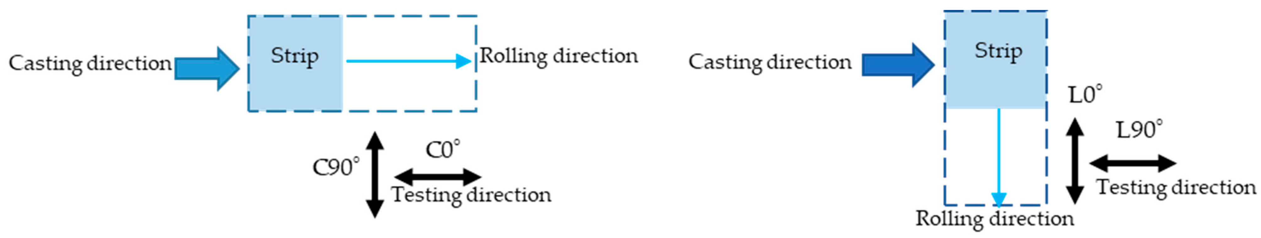
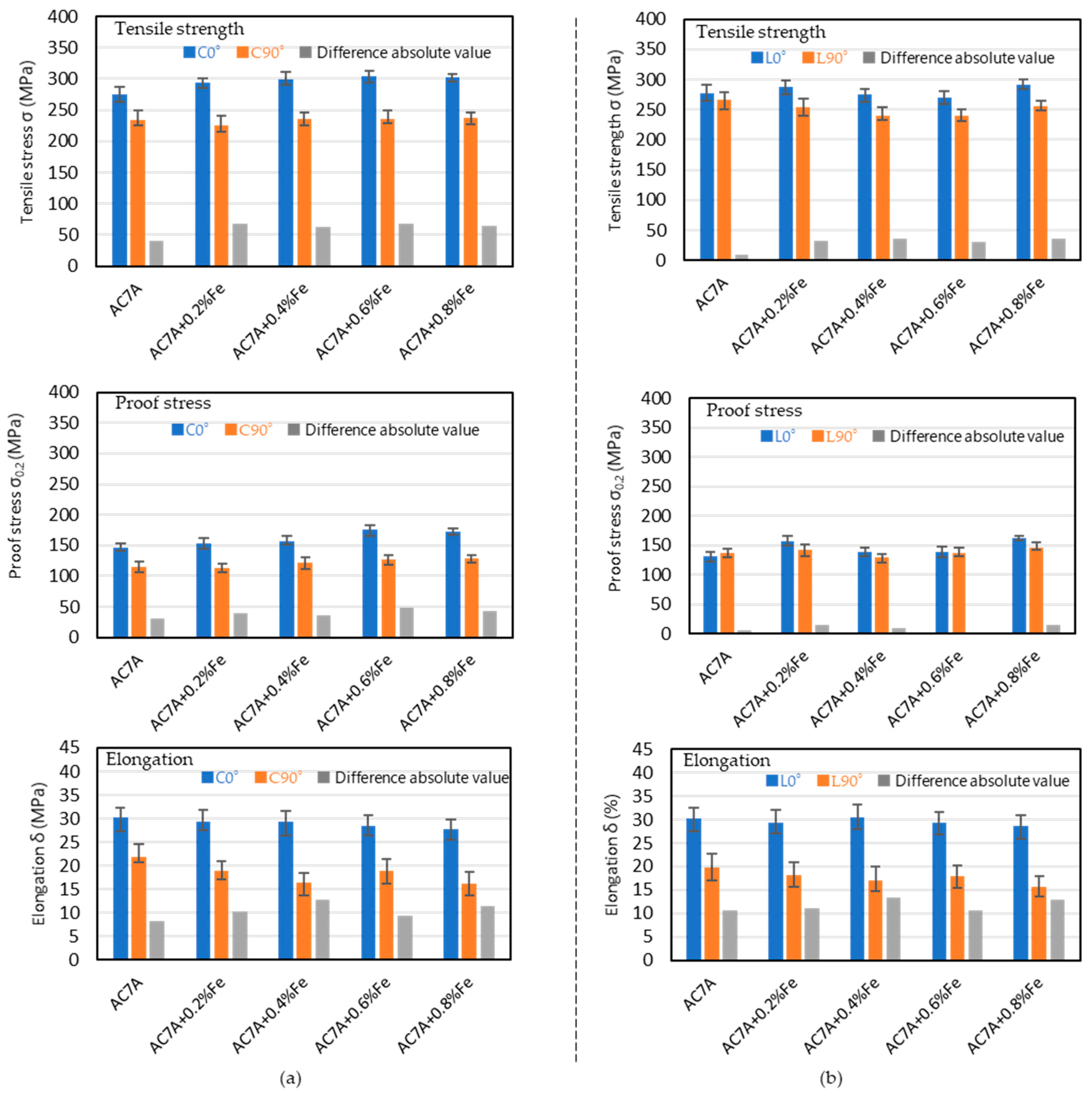
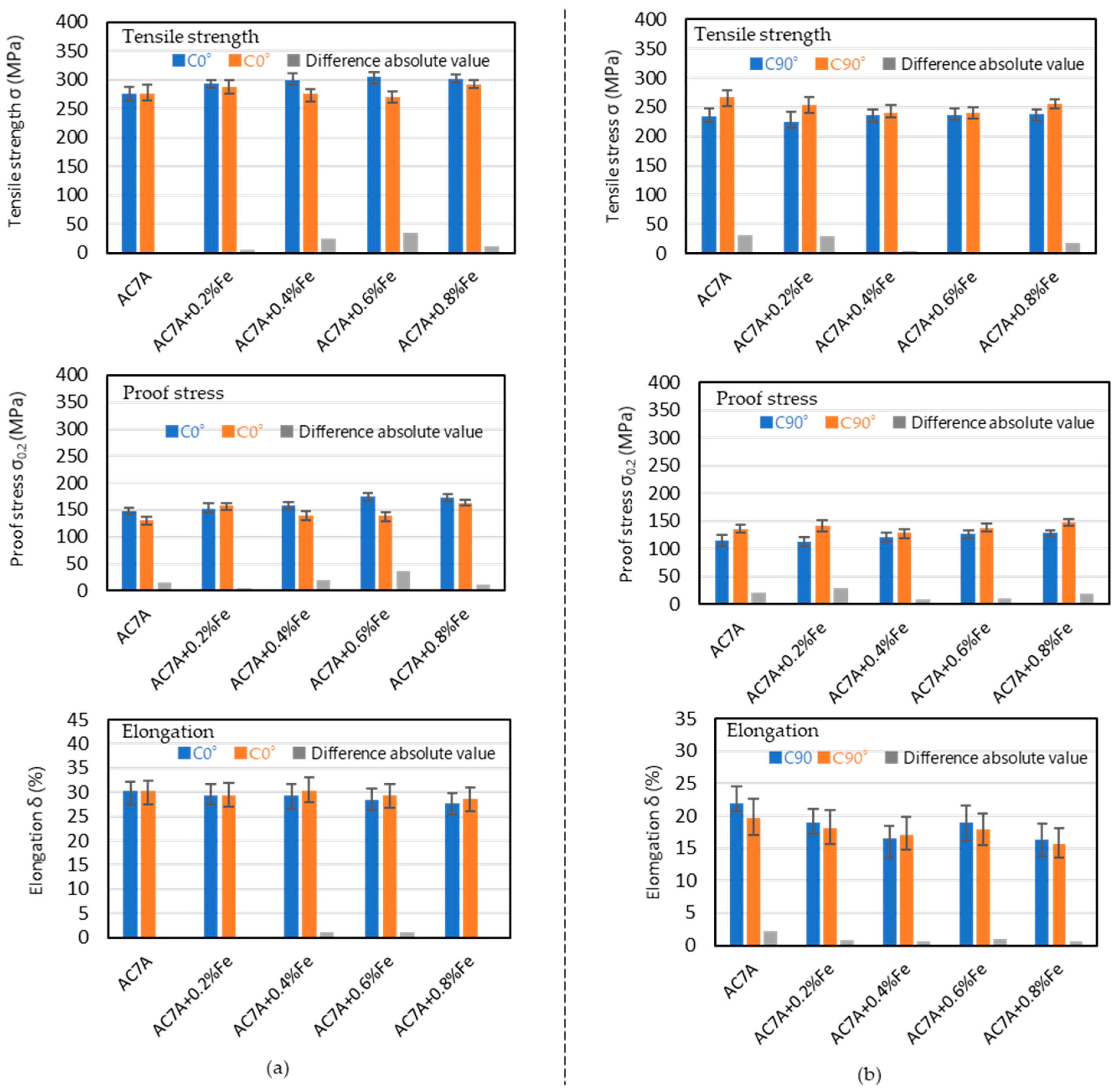
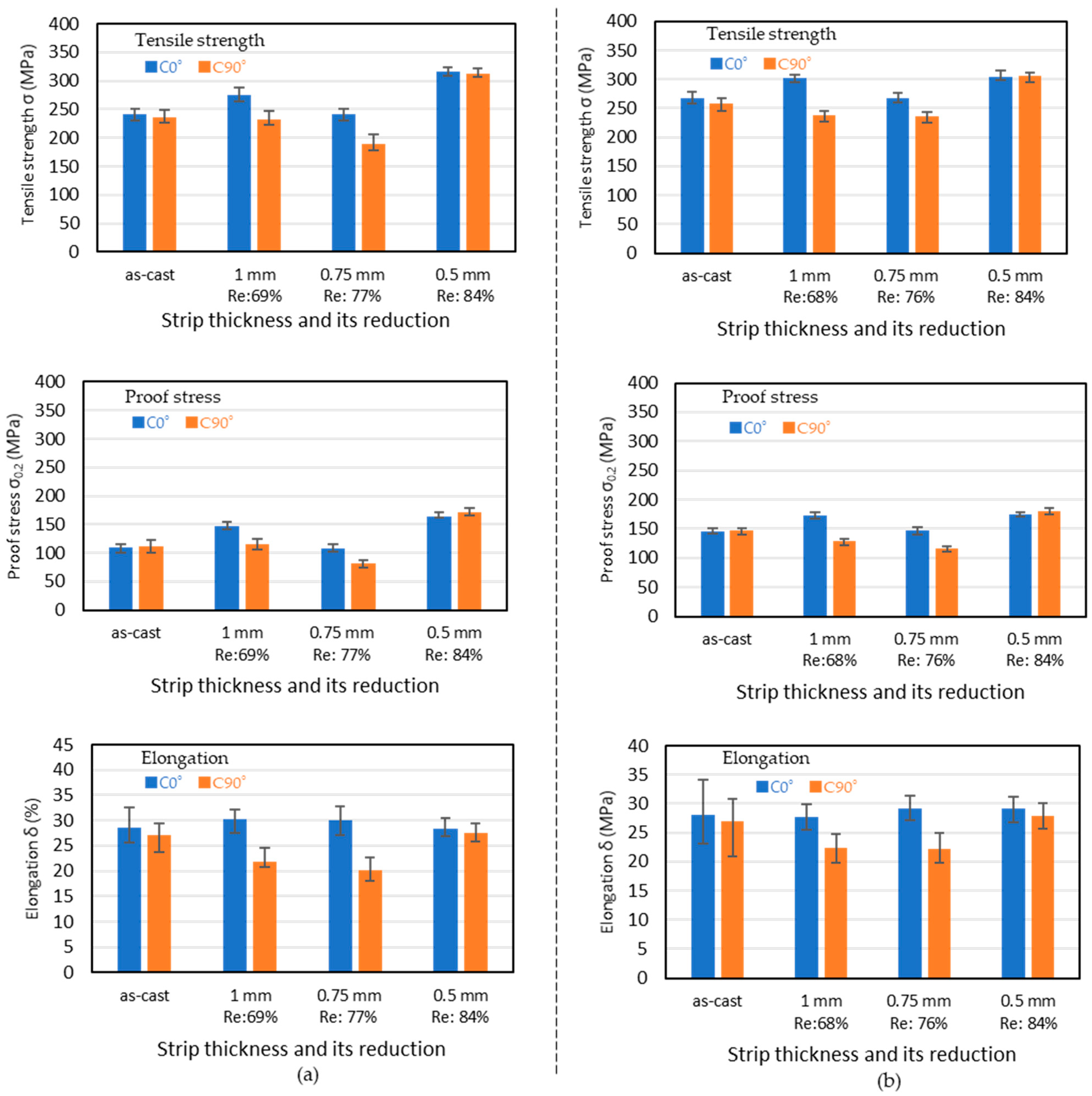
3.3. Effect of Rolling Direction on Anisotropy of Mechanical Property of the Strip Cast Using SRCS

As-cast strips formed using the SRCS were cold-rolled in two directions, the casting direction and the lateral direction, and annealed at 360 °C for 90 min. Tensile tests were conducted in the rolling direction and direction normal to the rolling direction as shown in Figure 10, which also shows symbols denoting the rolling direction and tensile test direction.
The results of tensile testing of the strip cold-rolled down to 1 mm are shown in Figure 11. The absolute difference between the C0° and C90° directions and the L0° and L90° directions are also shown in Figure 11. Differences in the tensile strength and proof stress between the L0° and L90° strips were smaller than those between the C0° and C90° directions. The proof stress for the L0° and L90° directions was almost the same. The elongation was different between the C0° and C90° directions and the L0° and L90° directions. The elongations for the C0° and L0° directions were larger than those for the C90° and L90° directions. The effect of the rolling direction on the elongation differences between C0° and C90° and that between L0° and L90° were almost the same. The elongation anisotropy between the C0° and C90° directions and the L0° and L90° directions was larger than the tensile strength and proof stress anisotropy. The increased Fe content did not influence the anisotropy of the mechanical properties. When the strips cast using the UDTRC and SRCS were cold-rolled down to 1 mm, elongation anisotropy was present between the direction parallel to the rolling direction and the normal direction to the rolling direction. The band area was present in the strip cast using the UDTRC but not in the strip cast using the SRCS. The band area may not be the cause of the elongation anisotropy. The tensile test results for the strips using the SRCS were better than those for the strips cast using the UDTRC. The cause may be the existence of the band area.
A comparison of the results of tensile tests in the same testing direction against the cold rolling direction is shown in Figure 11. The result of tensile tests for the C0° and L0° directions and the C90° and L90° directions are compared in Figure 12. The results of the tensile tests shown in Figure 11 were used. Different absolute values between C0° and L0° and C90° and L90° are also shown. When the results of the tensile testing were compared in the same testing direction, C0°/L0° and C90°/L90°, against the rolling direction, the difference was small. Especially, the difference in elongation was very small. The elongation anisotropy between the C0° and C90° directions and the L0° and L90° directions was larger than the tensile strength and proof stress anisotropy. The difference in elongation between testing directions against the cold rolling direction may be caused by the cold rolling process. We conclude that cold rolling may dominate the elongation anisotropy. The added Fe content did not influence these results. The effect of the thickness reduction due to cold rolling on the elongation anisotropy was investigated.
The effect of thickness reduction by cold rolling on the difference in the mechanical properties of the AC7A and AC7A + 0.8%Fe between C0° and C90° is shown in Figure 13. As-cast strips formed using the SRCS were cold-rolled in two directions, the casting direction and the lateral direction, and annealed at 360 °C for 90 min.
In Figure 13, the rolling direction is parallel to the casting direction. In the C0° direction for AC7A and AC7A + 0.8%Fe, the tensile strength and the proof stress increased by cold rolling from the as-cast condition down to 1 mm thick (reduction of 69%), decreased by cold rolling down to 0.75 mm (reduction of 77%), and increased by cold rolling down to 0.5 mm (reduction of 84%). In the C90° direction, the tensile strength and the proof stress increased by cold rolling down to 0.75 mm thick (reduction of 77%) and increased by cold rolling down to 0.5 mm (reduction of 84%). The tensile strength and the proof stress in both directions became almost the same at an 84% reduction. In the C0° direction, the elongation was almost uniform for every thickness reduction, which means that the elongation in the C0° direction is not influenced by the thickness reduction. In the C90° direction, the elongation decreased by cold rolling down to 0.75 mm (reduction of 77%), and it increased by cold rolling down to 0.5 mm (reduction of 85%). The elongation in both the C0° and C90° directions became almost the same when the reduction was 84%. This tendency is the same for both the AC7A and AC7A + 0.8%Fe alloys. It became clear that the elongation anisotropy can be reduced to a very small value for a thickness reduction greater than 84% and one-time annealing. The Fe impurity did not influence the reduction of the elongation anisotropy.
When a strip was cold-rolled down to 0.75 mm, the mechanical properties were the worst. The cause for this is not clear. The mechanical properties of the strips cast using the SRCS and cold-rolled to 1.0 mm and 0.5 mm thick were better than those of strips cast using the UDTRC. The cause may be the band area of the strip cast using the UDTRC.
Cross sections of the AC7A strips cold-rolled down to 0.5 and 0.75 mm and annealed at 360 °C for 90 min are shown in Figure 14. When the strip thickness was 0.75 mm, the elongation normal to the rolling direction was much smaller than that parallel to the rolling direction. However, there was no difference in the grain structure in the cross sections between the parallel and normal cross sections with respect to the rolling direction. When the strip thickness was 0.5 mm, the elongations parallel and normal to the rolling direction were almost the same. There was no difference in the grain structure. How the anisotropy of plasticity had come up is not clear. The texture differences may play a role but this will be part of future work.

4. Conclusions

Cold-rolled and annealed strips from a roll-cast Al-5%Mg strip have elongation anisotropy. The ability to reduce this anisotropy only by cold rolling and one-time annealing was investigated.
The elongation anisotropy was reduced by cold rolling and one-time annealing when the cold-rolling thickness reduction was greater than 84%.
The band area existing in the center area in the thickness direction did not influence the elongation anisotropy but did negatively affect the mechanical properties.
Up to 0.8% Fe was added to the Al-5%Mg alloy to simulate recycled Al-5%Mg. The addition of the Fe did not influence the elongation anisotropy, and the elongation anisotropy for the Fe-added Al-5%Mg could be reduced only by cold rolling and one-time annealing when the cold rolling thickness reduction was greater than 84%, similar to the case for Al-5%Mg without Fe.

Funding

The author declare that this study received funding from SUZUKI FOUNDATION (https://www.suzukifound.jp/). The funder was not involved in the study design, collection, analysis, interpretation of data, the writing of this article or the decision to submit it for publication.

Data Availability Statement

The original contributions presented in the study are included in the article, further inquiries can be directed to the corresponding author.

Conflicts of Interest

The author declares no conflict of interest.

References

  1. Cook, R.; Cook, P.G.; Thomas, P.M.; Edmonds, D.V.; Hunt, J.D. Development of the twin-roll casting process. J. Mater. Process. Technol. 1995, 55, 76–84. [Google Scholar] [CrossRef]
  2. Hamer, S.; Romanowski, C.; Taraglio, B. Continuous casting and rolling of aluminum: Analysis of capacities, Product ranges and technology. Light Met. Age 2002, 60, 6–17. [Google Scholar]
  3. Gras, C.; Meredith, N.; Hunt, J.D. Microdefects for mation during the roll casting of Al-Mg-Mn aluminum alloys. J. Mater. Process. Technol. 2005, 167, 62–72. [Google Scholar] [CrossRef]
  4. Daaland, O.; Espedal, A.B.; Nedreberg, M.L.; Alvestad, I. Thin gage twin-roll casting, process capabilities and product quality. In Essential Readings in Light Metals; Springer: Cham, The Netherlands, 2016; Volume 3, pp. 989–996. [Google Scholar] [CrossRef]
  5. Li, Y.; He, C.; Li, J.; Wang, Z.; Wu, D.; Xu, G. A novel approach to improve the microstructure and mechanical properties of Al-Mg-Si aluminum alloys during twin-roll casting. Metals 2020, 13, 1713. [Google Scholar] [CrossRef]
  6. Xu, Z.; Wang, S.; Wang, H.; Song, H.; Li, S.; Chen, X. Effect of cooling rate on Microstructure and properties of twin-roll casting 6061 aluminum alloy sheet. Metals 2020, 10, 1168. [Google Scholar] [CrossRef]
  7. Barekar, N.S.; Dhindaw, B.K. Twin-roll casting of aluminum alloys—An 38 overview(Review). Mater. Manuf. Process. 2014, 39, 651–661. [Google Scholar] [CrossRef]
  8. Özel, F.; Başaran, A.; Belit, S.; İpek, S.K.; Demir, B. Investigation of Ripple Formation in Aluminum Flat Products Produced by Different Types of Twin Roll Casters. In Light Metals 2024; TMS 2024; The Minerals, Metals & Materials Series; Springer: Cham, The Netherlands, 2024; pp. 273–277. [Google Scholar] [CrossRef]
  9. Girard, G.; Veillette, F.; Roy, W. Mechanisms of Twin-Roll Caster Tips Degradation. In Light Metals 2024; TMS 2024; The Minerals, Metals & Materials Series; Springer: Cham, The Netherlands, 2024; pp. 1069–1077. [Google Scholar] [CrossRef]
  10. Zhang, S.Y.; Wang, X.; Mo, Y.T.; Wang, C.; Cheng, T.; Ivasishin, O.; Wang, H.Y. Towards relieving center segregation in twin-roll cast Al-Mg-Si-Cu strips by controlling the thermal-mechanical process. J Mater. Sci. Tech. 2023, 148, 31–40. [Google Scholar] [CrossRef]
  11. Kim, M.S.; Kim, J. Metallurgical Method of Determining Heat Transfer Coefficient in Simulations of Twin-Roll Casting. Metals 2024, 14, 358. [Google Scholar] [CrossRef]
  12. Grandfield, J.F.; McGlade, P.T. DC casting of aluminium: Process behaviour and technology. Mater. Forum 1996, 20, 29–51. [Google Scholar]
  13. Schneider, W.D.C. Casting of Aluminum Alloys—Past, Present and Future. In Light Metals 2002; Schneider, W., Ed.; The Minerals, Metals & Materials Society: Warrendale, PA, USA, 2002; pp. 953–960. [Google Scholar]
  14. Haga, T.; Takahashi, K.; Ikawa, M.; Watari, H. A vertical type twin roll caster for aluminum alloy strip. J. Mater. Process. Technol. 2003, 140, 610–615. [Google Scholar] [CrossRef]
  15. Haga, T.; Suzuki, S. Study on a high-speed twin roll caster for aluminum alloys. J. Mater. Process. Technol. 2006, 143, 895–900. [Google Scholar] [CrossRef]
  16. Haga, T. Development of a twin roll caster for light metals. J. Achiev. Mater. Manuf. Eng. 2010, 43, 393–402. [Google Scholar]
  17. Haga, T. High Speed Roll Caster for Aluminum Alloy. Metals 2021, 11, 520. [Google Scholar] [CrossRef]
  18. Haga, T.; Ikawa, M.; Suzuki, K.; Kumai, S. 6111 aluminum alloy strip casting using an unequal diameter twin roll caster. J. Mater. Process. Technol. 2006, 172, 271–276. [Google Scholar] [CrossRef]
  19. Haga, T.; Inui, H.; Watari, H.; Kumai, S. Casting of Al–Si hypereutectic aluminum alloy strip using an unequal diameter twin roll caster. J. Mater. Process. Technol. 2007, 191, 238–241. [Google Scholar] [CrossRef]
  20. Ding, C.; Yuan, G.; Guo, H.; Long, Z.; Yuan, O. Effect of Microstructure on the anisotropy of the roll casting strip of cold rolled 3003 aluminum alloy. Phys. Eng. Metall. Mater. 2018, 217, 635–644. [Google Scholar] [CrossRef]
  21. Gras, C.; Meredith, M.; Hunt, J.D. Microstructure and texture evolution after twin toll casting and subsequent cold of Al-Mg-Mn aluminum alloys. J. Mater. Process. Technol. 2005, 169, 156–163. [Google Scholar] [CrossRef]
  22. Grydin, O.Y.; Pgins’ky, Y.K.; Danchenko, V.M.; Bach, F.W. Experimental twin-roll casting equipment for production of thin strips. Metall. Min. Ind. 2010, 2, 348–354. [Google Scholar]
  23. Ye, F.; Mao, L.; Rong, J.; Zhang, B.; Wei, L.; Wen, S.; Jiao, H.; Wu, A. Influence of different rolling process on microstructure and strength of the Al-Cu-Li alloy AA2915. Prog. Nat. Sci.-Mater. 2022, 32, 87–95. [Google Scholar] [CrossRef]
  24. Takehara, Y.; Ito, Y.; Nguyen, T.H.; Harada, Y.; Muraishi, S.; Kumai, S. Effect of homogenization heat treatment on elongation anisotropy in cold-rolled and annealed Al-Si alloy sheets fabricated from vertical type-high-speed twin roll cast strips. Mater. Trans. 2023, 64, 379–384. [Google Scholar] [CrossRef]
  25. Jin, T.; Xiao, L.; Ding, L.; Zhao, X.; Lei, X.; Wan, B.; Weng, Y.; Jia, Z.; Liu, Q. Effect of homogenization temperature on microstructural homogeneity and mechanical properties of twin-roll casted 8006 aluminum alloy. Mater. Charact. 2023, 200, 112857. [Google Scholar] [CrossRef]
  26. Kabil, A.; Mollaoğlu, A.H.; Meydanoglu, O. Effect of Cold Rolling Prior to Homogenization Heat Treatment on the Microstructural Evolution and Mechanical Properties of Twin-Roll Cast 8026 Aluminum Alloy. In Light Metals 2024; TMS 2024; The Minerals, Metals & Materials Series; Springer: Cham, The Netherlands, 2024; pp. 362–368. [Google Scholar] [CrossRef]
  27. Zhao, X.; Jin, T.; Ding, L.; Wan, B.; Lei, X.; Xu, C.; Zhang, C.; Jia, Z.; Liu, Q. The effect of combined cold rolling and homogenization on the microstructures and mechanical properties of twin-roll casted 8021 aluminum alloy. J. Alloys Compd. 2023, 937, 168385. [Google Scholar] [CrossRef]
  28. Goda, T.; Kumai, S. Microstructure and elongation anisotropy of cold rolled and solution treated A356 alloy strips fabricated via high-speed twin roll casting. Mater. Trans. 2018, 59, 1777–1783. [Google Scholar] [CrossRef]
  29. Jin, J.W.; Zhang, Z.J.; Li, R.H.; Li, Y.; Gong, B.S.; Hou, J.P.; Wang, H.W.; Zhou, X.H.; Purcek, G.; Zhang, Z.F. Mechanical properties of three typical aluminum alloy strips prepared by twin-roll casting. J. Mater. Res. Technol. 2024, 28, 500–511. [Google Scholar] [CrossRef]
  30. Ren, X.; Huang, Y.; Liu, Y.; Zhang, X.; Zhao, L.; Zhou, W. Through-thickness shear texture of the twin-roll cast AA6016 sheet after asymmetric rolling and its recrystallization behavior. J. Mater. Res. Technol. 2021, 10, 1323–1338. [Google Scholar] [CrossRef]
  31. Cho, J.H.; Kim, H.W.; Lim, C.Y.; Kang, S.B. Microstructure and mechanical properties of Al-Si-Mg alloys fabricated twin roll casting and subsequent symmetric and asymmetric rolling. Met. Mater. Int. 2014, 20, 647–652. [Google Scholar] [CrossRef]
  32. Haga, T.; Tsukuda, K.; Oida, K.; Watari, H.; Nishida, S. Casting of Al-Mg Strip Using Single Roll Caster Equipped with a Scraper. Key Eng. Mater. 2021, 880, 49–56. [Google Scholar] [CrossRef]
  33. Harada, Y.; Jiang, N.; Kumai, S. Mechanical Properties of Cold-Rolled and Annealed Al-12%Mg alloy Sheet with High Mg Solid Solubility Fabricated from Vertical-Type High-Speed Twin Roll Cast Strip. Mater. Trans. 2019, 60, 2435–2441. [Google Scholar] [CrossRef]
  34. Kim, M.S.; Kim, H.E.; Kim, S.H.; Kumai, S. Role of Roll Separating Force in High-Speed Twin-Roll Casting of Aluminum Alloys. Metals 2019, 9, 645. [Google Scholar] [CrossRef]
  35. JIS H 5202: 2010(E); Aluminum Alloy Castings. Japanese Indudtrial Standerds: Tokyo, Japan, 2010.
  36. Yamazaki, K.; Haga, T. Effect of casting conditions on surface defect and segregation of strips cast by a high-speed twin-roll caster. Mater. Trans. 2023, 64, 366–372. [Google Scholar] [CrossRef]
Figure 1. Schematic diagrams of UDTRC and SRCS. (a) Overview of UDTRC. (b) Overview of SRCS. (c) Enlarged view around the scraper of SRCS.
Metals 14 00965 g001
Figure 2. Schematic diagram of bending test and dimensions of test piece for tensile test. (a) Bending test. (b) Test piece for tensile test.
Metals 14 00965 g002
Figure 3. Surfaces of as-cast strip, bending test of as-cast strip, and penetrant testing of cold-rolled surfaces of AC7A strips cast using an UDTRC. (a) As-cast strip. (b) Bending of as-cast strip. (c) Cold-rolled down to 1 mm. (d) Cold-rolled down to 0.5 mm.
Metals 14 00965 g003
Figure 4. Cross sections of as-cast strip and cold-rolled strips of AC7A cast using an UDTRC. Cast strips were cold-rolled down to 0.5 and 1 mm. Cold-rolled strips were annealed at 360 °C for 90 min. (a) As-cast strip. (b) Cold-rolled down to 1 mm. Reduction: 73%. (c) Cold-rolled down to 0.5 mm. Reduction: 86%.
Metals 14 00965 g004
Figure 5. Result of tensile testing of cold-rolled strips of AC7A cast using an UDTRC. Cast strips were cold-rolled down to 1 mm (reduction of 73%) and 0.5 mm (reduction of 96%). Cold-rolled strips were annealed at 360 °C for 90 min.
Metals 14 00965 g005
Figure 6. Cross sections of as-cast and 1 mm thickness cold-rolled strips of AC7A cast using a SRCS. The cold-rolled strip was annealed at 360 °C for 90 min. Lower surface is roll contact surface and upper surface is scribed surface by scraper. (a) As-cast strip. (b) Cold-rolled strip.
Metals 14 00965 g006
Figure 7. Surfaces of as-cast strips and cold-rolled strips. Lower surface is roll contact surface and upper surface is scribed surface by the scraper. The cold-rolled strip is 1 mm in thickness. (a) As-cast strip, (b) Cold-rolled strip.
Metals 14 00965 g007
Figure 8. Results of bending tests of as-cast AC7A and Fe-added AC7A strips.
Metals 14 00965 g008
Figure 9. Thickness of as-cast AC7A and Fe-added AC7A strips.
Metals 14 00965 g009
Figure 10. Rolling direction, tensile testing direction and their symbols.
Metals 14 00965 g010
Figure 11. Results of tensile testing of strips cold-rolled in parallel and vertical directions with respect to casting direction down to 1 mm. Cold-rolled strips were at 360 °C for 90 min. Tensile tests were conducted in directions parallel to and vertically against the rolling direction, and the absolute of differences between the parallel and vertical directions against the rolling direction are also shown. The symbols of C0°, C90°, L0°, and L90° are explained in Figure 10. (a) Rolling direction is parallel to casting direction. (b) Rolling direction is vertical to casting direction.
Metals 14 00965 g011
Figure 12. Comparison of the results of tensile tests in the same testing direction against the cold rolling direction when the cold rolling direction is different. Results of the tensile tests shown in Figure 11 were used. Absolute difference values between C0° and L0° and C90° and L90° are also shown. The symbols of C0°, C90°, L0°, and L90° are explained in Figure 10. (a) Testing direction: parallel to rolling direction. (b) Testing direction: vertical to rolling direction.
Metals 14 00965 g012
Figure 13. Effect of cold rolling thickness reduction on results of tensile tests between testing directions. Cold rolling direction is parallel to the casting direction. Cold-rolled strips were at 360 °C for 90 min before tensile testing. The symbols C0°, C90°, L0°, and L90° are explained in Figure 10. (a) AC7A; (b) AC7A + 0.8%Fe.
Metals 14 00965 g013
Figure 14. Cross sections of cold-rolled and annealed AC7A strips. Strips were cold-rolled down to 0.5 and 0.75 mm and annealed at 360 °C for 90 min. Cross sections were viewed from parallel and vertical to the rolling direction. (a) Cold-rolled strip thickness of 0.75 mm. (b) Cold-rolled strip thickness of 0.5 mm.
Metals 14 00965 g014
Table 1. Chemical compositions of Al-5%Mg and Fe added AC7A alloys (mass%).
Aluminum AlloyCuSiMgZnFeMnAl
JIS AC7A0.020.104.860.010.160.44Bal.
AC7A + 0.2%Fe0.030.114.840.010.380.42Bal.
AC7A + 0.4%Fe0.020.124.850.030.520.43Bal.
AC7A + 0.6%Fe0.040.094.830.020.770.43Bal.
AC7A + 0.8%Fe0.030.114.820.020.930.44Bal.
Disclaimer/Publisher’s Note: The statements, opinions and data contained in all publications are solely those of the individual author(s) and contributor(s) and not of MDPI and/or the editor(s). MDPI and/or the editor(s) disclaim responsibility for any injury to people or property resulting from any ideas, methods, instructions or products referred to in the content.

