Article

Enhanced Strength–Ductility Combination in Laser Welding of CrCoNi Medium-Entropy Alloy with Ultrasonic Assistance

1
School of Materials and Environmental Engineering, Chengdu Technological University, Chengdu 611730, China
2
College of Physics and Optoelectronic Engineering, Shenzhen University, Shenzhen 518060, China
3
Engineering Training Center, Southwest Jiaotong University, Chengdu 610031, China
*
Author to whom correspondence should be addressed.
Metals 2024, 14(9), 971; https://doi.org/10.3390/met14090971
Submission received: 24 June 2024 / Revised: 24 July 2024 / Accepted: 31 July 2024 / Published: 27 August 2024
(This article belongs to the Section Entropic Alloys and Meta-Metals)

Abstract

:
The welded joints of high/medium entropy alloys (H/MEAs) have shown sound mechanical properties, indicating high promise for the industrial application of this new type of metal alloy. However, these joints possess either relatively low strength or low ductility. In this paper, we used ultrasonic-assisted laser welding to weld CrCoNi MEA with the nitrogen as shielding gas. The results showed that the tensile strength of the joint at room and cryogenic temperature is 686 MPa and 1071 MPa, respectively. The elongation at room and cryogenic temperature is 26.8% and 27.7%, respectively. The combination of the strength and ductility in our joints exceeds that of other welded H/MEA joints. We attributed this excellent combination to the refined dendrite, the solution of nitrogen into the matrix, and the low stacking fault energy of the CrCoNi MEA. The findings in this paper not only provide a novel way to weld H/MEAs with high strength and ductility, also are useful for additively manufacturing the high-performance component of H/MEAs.

1. Introduction

Medium/high-entropy alloys (M/HEAs), first introduced by Yeh et al. [1] and Cantor et al. [2], have been considered as one of the three major breakthroughs in alloy theories in recent decades. These M/HEAs consist of at least three chemical elements in either equal or non-equal ratios, which leads to a large number of new alloys [3,4]. M/HEAs show a great combination of strength, ductility, and toughness, which exceeds that of conventional metal alloys [1,5,6,7,8,9,10,11,12,13]. Thus, this new type of metal alloy has high potential in real applications. Among the M/HEAs, CrCoNi MEA possesses the best combination of strength, ductility, and fracture toughness [1,5,6,7,8,9,10,14,15].
To further examine the potential usage of M/HEAs in industry, studies have been conducted to investigate the microstructure and mechanical properties of the joints of M/HEAs fabricated by various welding methods, which include TIG [16,17,18,19,20,21,22], FSW [23,24,25], laser welding [26,27,28,29,30,31,32,33,34,35,36,37], electron beam welding [38,39,40,41,42,43,44] and diffusion welding [45,46,47,48,49,50]. These joints have shown either excellent strength or sound ductility, which demonstrate the great promise of industrial applications. However, the combination of the tensile strength and ductility in these welded joints is not desirable, which hinders the real application of this new type of metal alloy. For example, Peng et al. [51] reported that electron beam (EB)-welded NiCoCrAl3Ti3 joints showed a high tensile strength of 1.37 GPa, but a low ductility of ~11%. Li et al. [52] showed that the EB-welded joints of a TiZrNbTa refractory high-entropy alloy indicated a tensile strength of 940 MPa but only had 9% ductility. Chen et al. [53] found that gas tungsten arc-welded joints of (FeCoNi)96Al4 HEA exhibited a high ductility of 61%, but a low tensile strength of 435 MPa. Therefore, the question of how to improve the combination of mechanical properties is a primary task for promoting the real application of M/HEAs.
In this paper, CrCoNi MEA was joined using ultrasonic-assisted laser welding based on two concepts, namely (1) the refining of the dendrites via the ultrasonic force, and (2) solute of interstitial N atoms to induce interstitial strengthening. Both concepts can increase the lattice friction and dislocation densities, resulting in an improved strength without sacrificing the ductility [54]. An ultrasonic-assisted laser welding apparatus was first built, and then used to join CrCoNi MEA. The microstructure was examined using optical microscopy, scanning electron microscopy (SEM), and electron backscattered diffraction (EBSD) testing. Mechanical properties at 300 K and 77 K were tested and compared to those of other welded H/MEAs. The deformation mechanisms were explored using experiments. The aim of this work is to demonstrate that ultrasonic-assisted laser welding is a novel process to join metal and its alloys with high strength and high ductility.

2. Materials and Methods

2.1. Materials

The base metal (BM) in this study was a CrCoNi medium-entropy alloy. The BM was prepared via arc-melting the chemical elements of Cr, Co, Ni with a purity higher than 99%. The melting was performed for five times to achieve good chemical homogeneity. The BM was further homogenized at 1100 °C for 24 h, and rolled with a thickness reduction of ~80%. The rolled sample was annealed at 900 °C for 15 min. The content of Cr, Co and Ni in the obtained BM was 31.4 wt.%, 35.17 wt.%, and 33.14 wt.%, respectively. The geometry of the obtained BM was 50 mm length, 30 mm width, and 1.5 mm thickness.
To further reveal the microstructure of the base material, EBSD testing was conducted, and the results are shown in Figure 1. Figure 1a indicates that the microstructure after rolling and annealing is a fully recrystallized structure, with grain sizes ranging from 1 to 15 µm and an average grain size of 6.5 µm. In Figure 1b, the red lines represent Σ = 60° twin boundaries, indicating that a significant amount of annealing twins were generated in the CrCoNi MEA after annealing, following the rolling process.

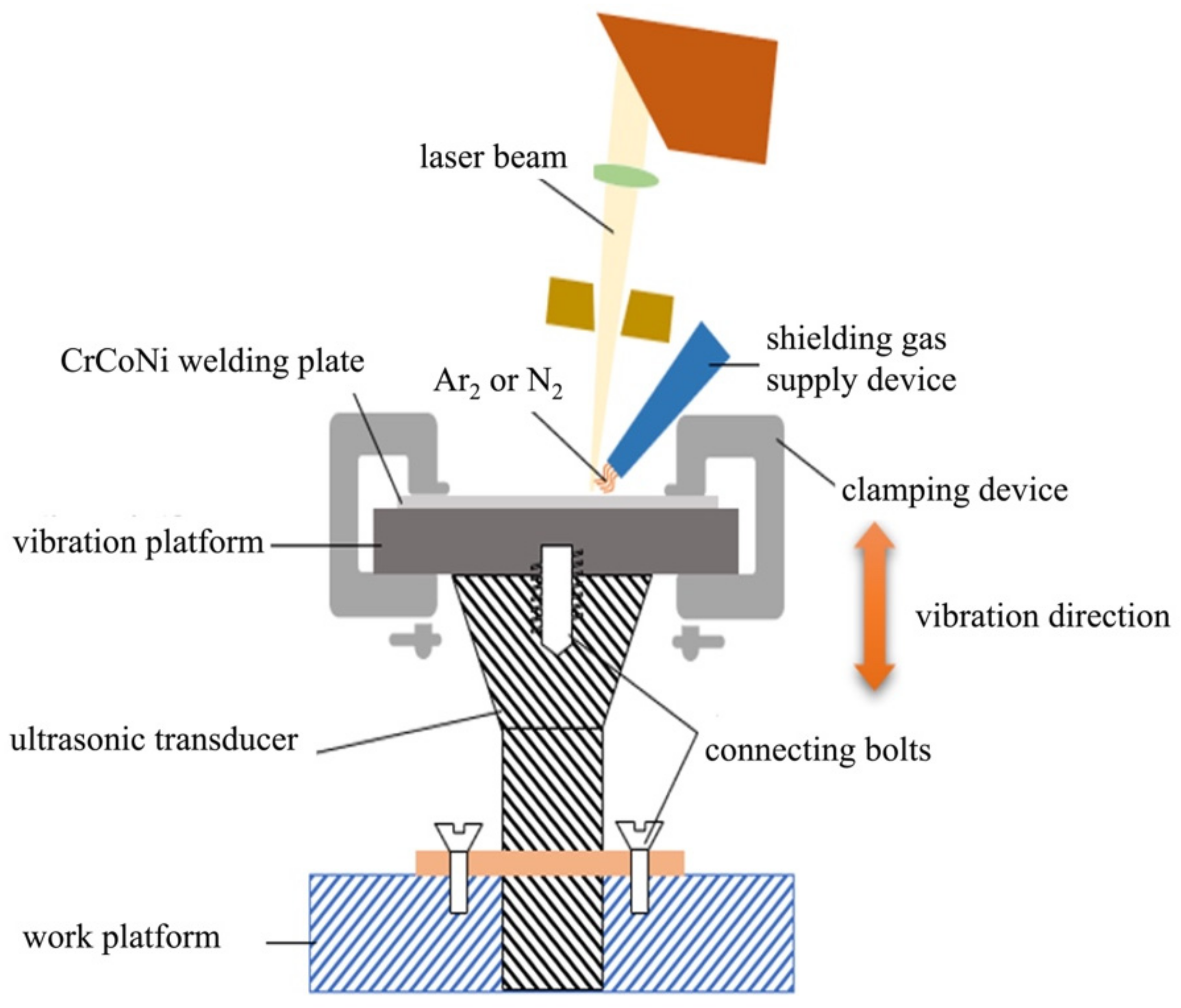
2.2. Welding Process

The application mode of auxiliary ultrasound primarily includes applying through the base material, applying through the welding wire, using an ultrasonic probe, and applying through an electric arc. Among these, applying ultrasonic assistance through the base material has become the most commonly used method due to its convenience of operation and uniform energy distribution, which is also the method used in this paper. As shown in Figure 2, the constructed ultrasonic-assisted laser welding system in this paper primarily consisted of three components: the laser welding system, the ultrasonic vibration device, and the test plate clamping platform. The main components of the ultrasonic vibration device included an ultrasonic generator, an ultrasonic transducer, an amplitude-modulating rod, and a vibration platform. The inherent frequency of the ultrasonic transducer was set as 20 KHz with an actual operating frequency of ~19.8 KHz.
In order to study the effects of ultrasonic assistance and different shielding gasses on the microstructure and mechanical properties of the weld joint, we have designed a total of four different welding processes with detailed process parameters, as shown in Table 1. The welding test plates were not beveled, and no filler material was added during the welding process. Single-sided welding with double-sided formation was performed. Nitrogen gas (Process 2, Process 3, Process 4) and 99.999% pure argon gas (Process 1) were used to protect the weld pool. There was no welding gap between the assemblies, and the laser focus distance was set to 0 mm. Prior to welding, the test plates were cleaned with acetone and alcohol, and then dried for later use. In the ultrasonic-assisted laser welding process, we conducted trials with different ultrasonic powers and found that when the ultrasonic power exceeds 80 W, the intense mechanical vibrations introduced by ultrasonic assistance can lead to cracking in the joint during the solidification process. Therefore, we ultimately adopted an ultrasonic power of 80 W, with ultrasonic vibration applied along the normal direction of the BM.

2.3. Characterization of the Mechanical Properties and Microstructure

We cut cubic samples from the welded joint using electrical discharging machining. The cubic samples were then mechanically grinded and polished following the routine of references [55,56,57]. We etched some cubic samples with the solution of 3.75 g CuSO4, 1.8 mL H2SO4, and 25 mL HCl, and then examined the macroscopic microstructure of the joint under optical microscope (OM). We also carried out EBSD testing to reveal the type, size and morphology of the grains, and the orientations of the maps. Hardness testing along the cross section of the joint was conducted with 10 N load and 15 s holding time. Tensile testing was performed at room and cryogenic temperature at a constant strain rate of 1 × 10⁻³ s−1. At each temperature, at least three samples were tested to achieve an averaged value. Deformation mechanisms were analyzed via scanning electron microscope (SEM) and EBSD observation.

3. Results and Discussion

3.1. Microstructure

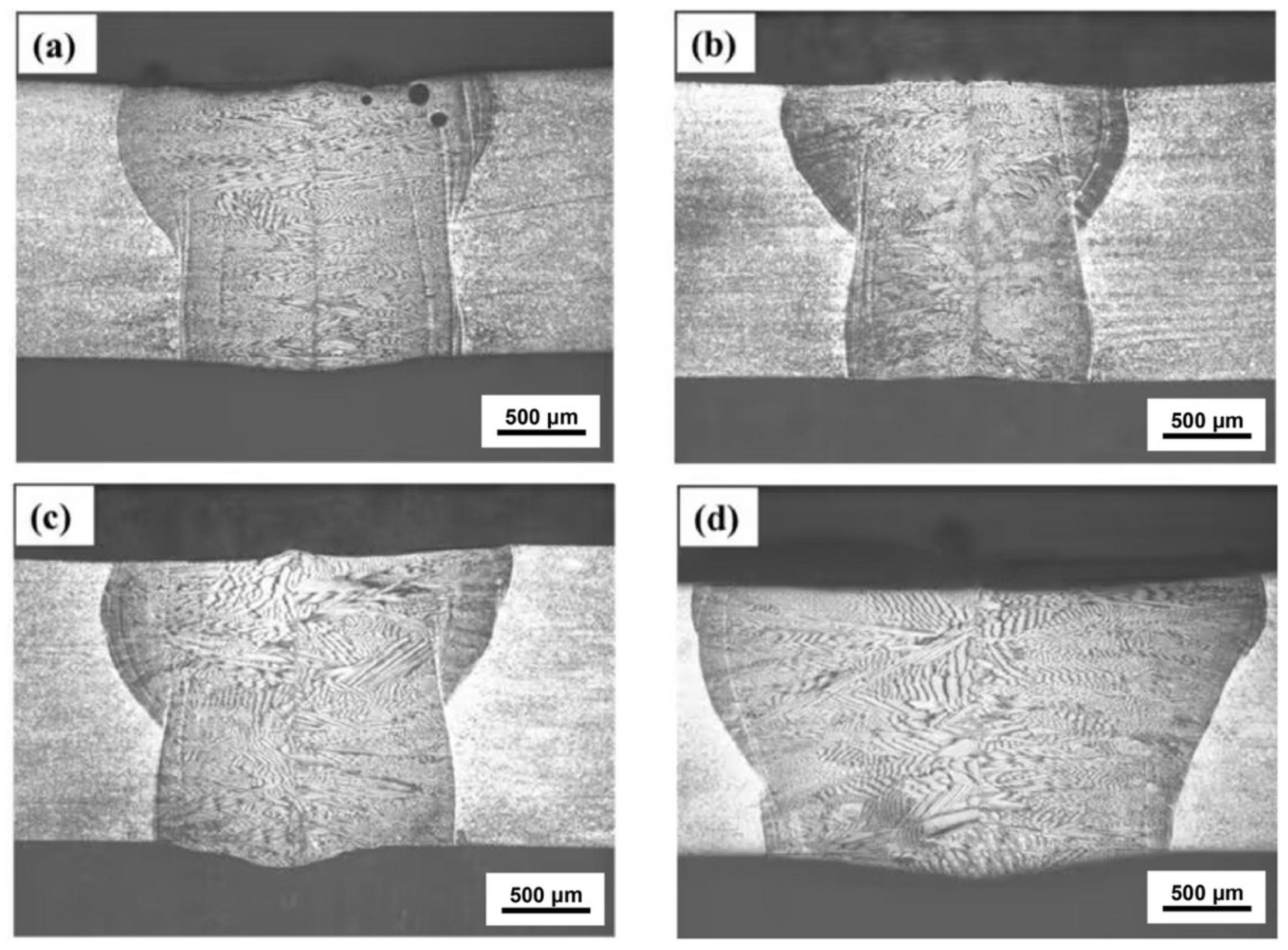
3.1.1. Macroscopic View of the Joint
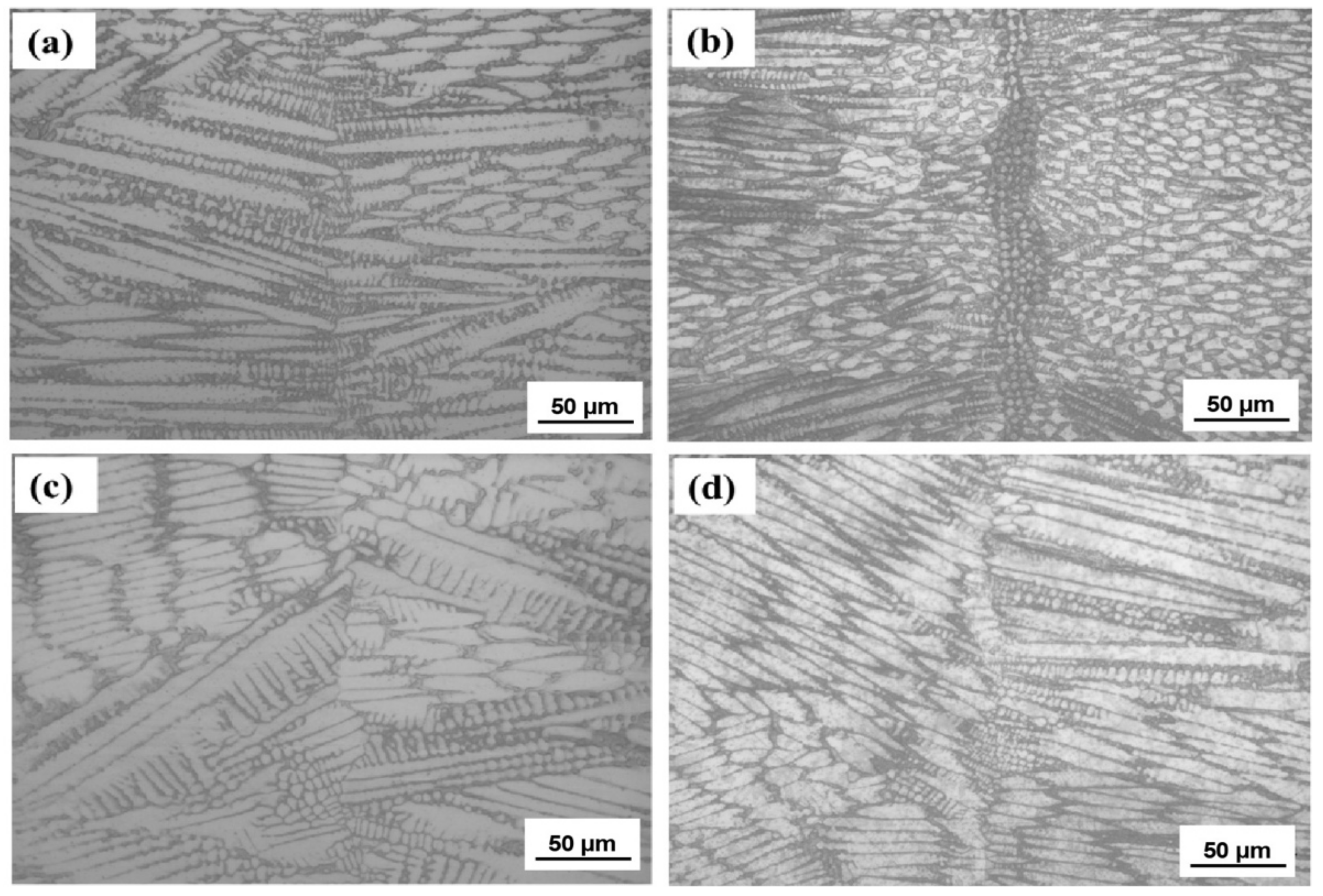
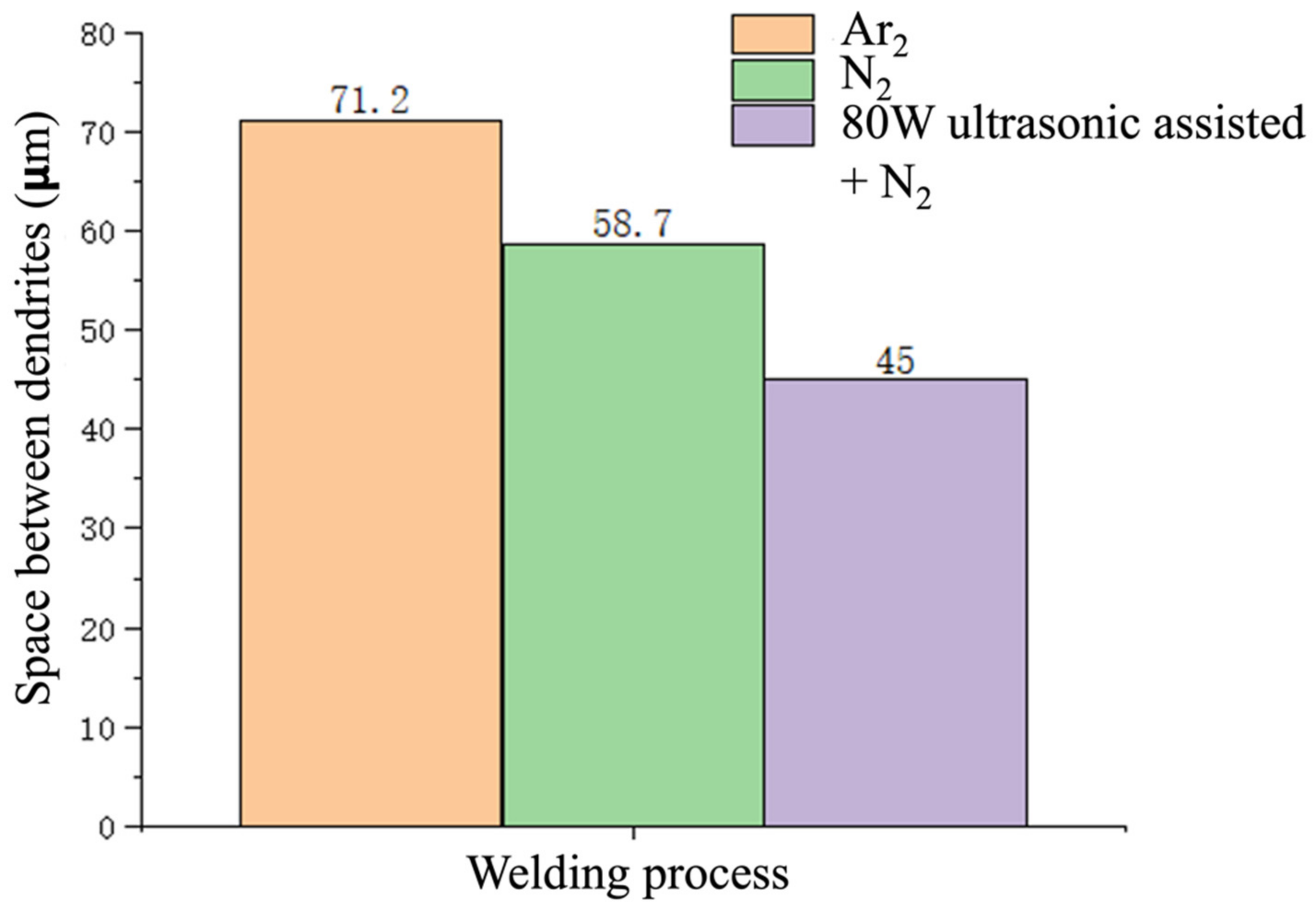
Comparing the weld seam appearances of the ultrasonic-assisted laser welding joint with the other two processes (as shown in Figure 3), it can be clearly observed that when 80 W ultrasonic assistance is introduced, both the top and bottom widths of the weld have significantly increased (as shown in Figure 4). Figure 4 summaries the width of the top and bottom of the weld seam, which further shows that the width of the weld increased when the ultrasonic involved. This is primarily due to the fact that, under the same laser power, the introduction of ultrasonic waves with non-linear effects such as cavitation and acoustic streaming in the melt pool enhances the fluidity of the melt pool [58,59].
Drezet et al. [60] also proposed that ultrasonic vibration enhances the Marangoni convection of the melt pool, which is directly proportional to the square of the melt pool size. Meanwhile, ultrasonic propagation in the welding melt pool process generates viscous losses and high temperature and high pressure caused by cavitation bubble rupture, increasing the internal energy of the melt pool. As a result, the energy density in the weld seam area increases, leading to higher temperatures within the melt pool. Therefore, in ultrasonic-assisted laser welding, the molten area is larger and more uniform.

3.1.2. Dendrites

From Figure 5, we can observe that the microstructure of the weld zone exhibits a distinct dendritic pattern. The dendrites in this structure have a laminar, sheet-like configuration, with their lengths oriented perpendicular to the solid–liquid interface. Upon the introduction of ultrasonic assistance, the dendrite space and size significantly decrease. To quantitatively analyze the effect of different welding process on the dendrite characters, we measured the space between dendrites, and the results are shown in Figure 6. The average space of columnar dendritic grains without ultrasonic assistance is 71.2 μm. After changing the welding shielding gas from argon to nitrogen, the average space decreases to 58.7 μm. With the addition of ultrasonic assistance, this space further reduces to 45 μm. The above findings suggest that using nitrogen as the welding shielding gas and applying ultrasonic assistance can significantly refine the dendrites. The mechanism of grain refinement through ultrasonic assistance can be explained from two aspects: (1) Ultrasonic assistance increases the nucleation rate; (2) ultrasonic induction grain fragmentation.
With the introduction of ultrasonic assistance, the dendritic structure within the weld zone is disrupted by the energy introduced by ultrasound, and this phenomenon is referred to as the “molten pool sound pressure effect”. Furthermore, as the ultrasonic power increases, the degree of dendrite fragmentation intensifies, leading to an increase in the molten pool sound pressure effect. The molten pool sound pressure introduced by ultrasonic assistance can be calculated by:
p = I ρ ν u
In the equation, I represents the acoustic intensity, ρ is the density of the molten pool medium, and ν u is the propagation velocity of ultrasound in the molten pool. The greater the ultrasonic power, the larger the amplitude, resulting in a higher acoustic intensity. This acoustic intensity, when applied to the dendrites, can cause dendritic fragmentation, ultimately leading to the formation of a laminar dendritic structure. Additionally, the higher the power, the more pronounced this effect becomes.

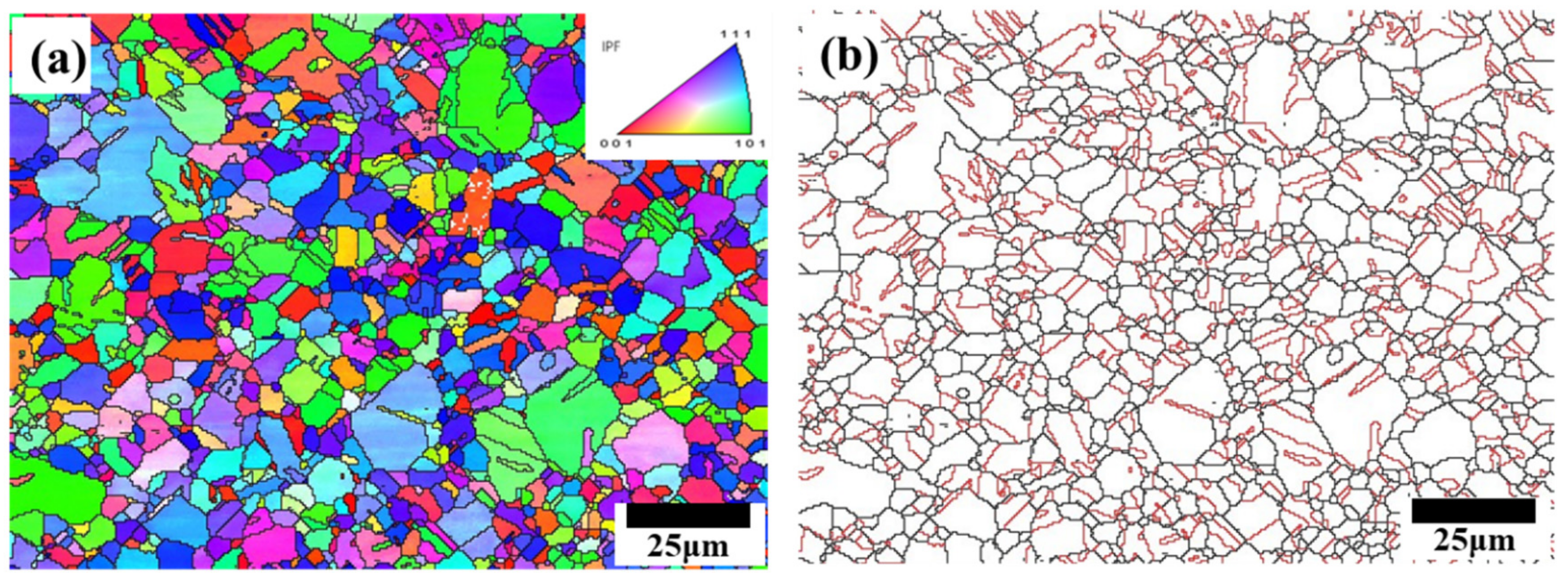
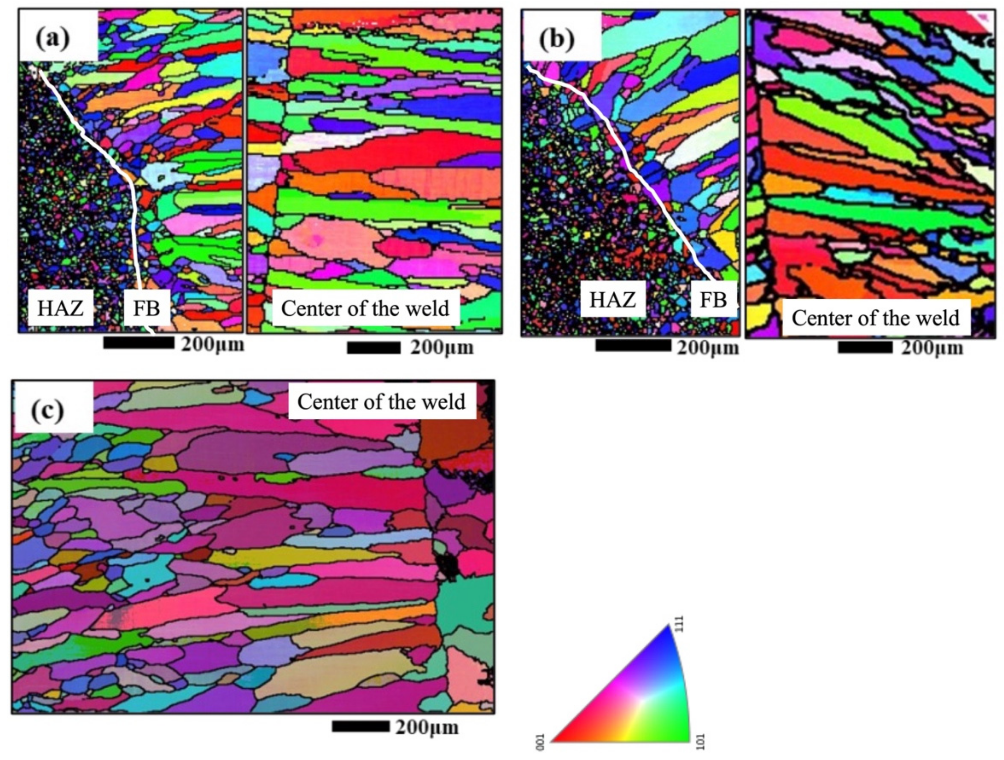
3.1.3. Grain Morphology

Figure 7 shows the experimental results of EBSD in the weld zone under different welding processes. We can see that the microstructure of the weld zone under different processes is mainly coarse columnar crystals, which start growing from the center of the weld and end up near the fusion line. In the center of the weld, there are a small number of smaller sized grains, which are disadvantaged in the competitive mechanism of grain growth, with limited grain growth drive and a therefore smaller final size.
The microstructure of the weld mainly depends on the solidification behavior of the molten pool during the welding process, including the size, shape and growth direction of the grains [61]. The temperature is highest at the center of the weld, and decreases gradually on approaching the fusion boundary. During the solidification of the molten pool, the grains grow from the fusion boundaries towards the center of the weld when the pool cools significantly.

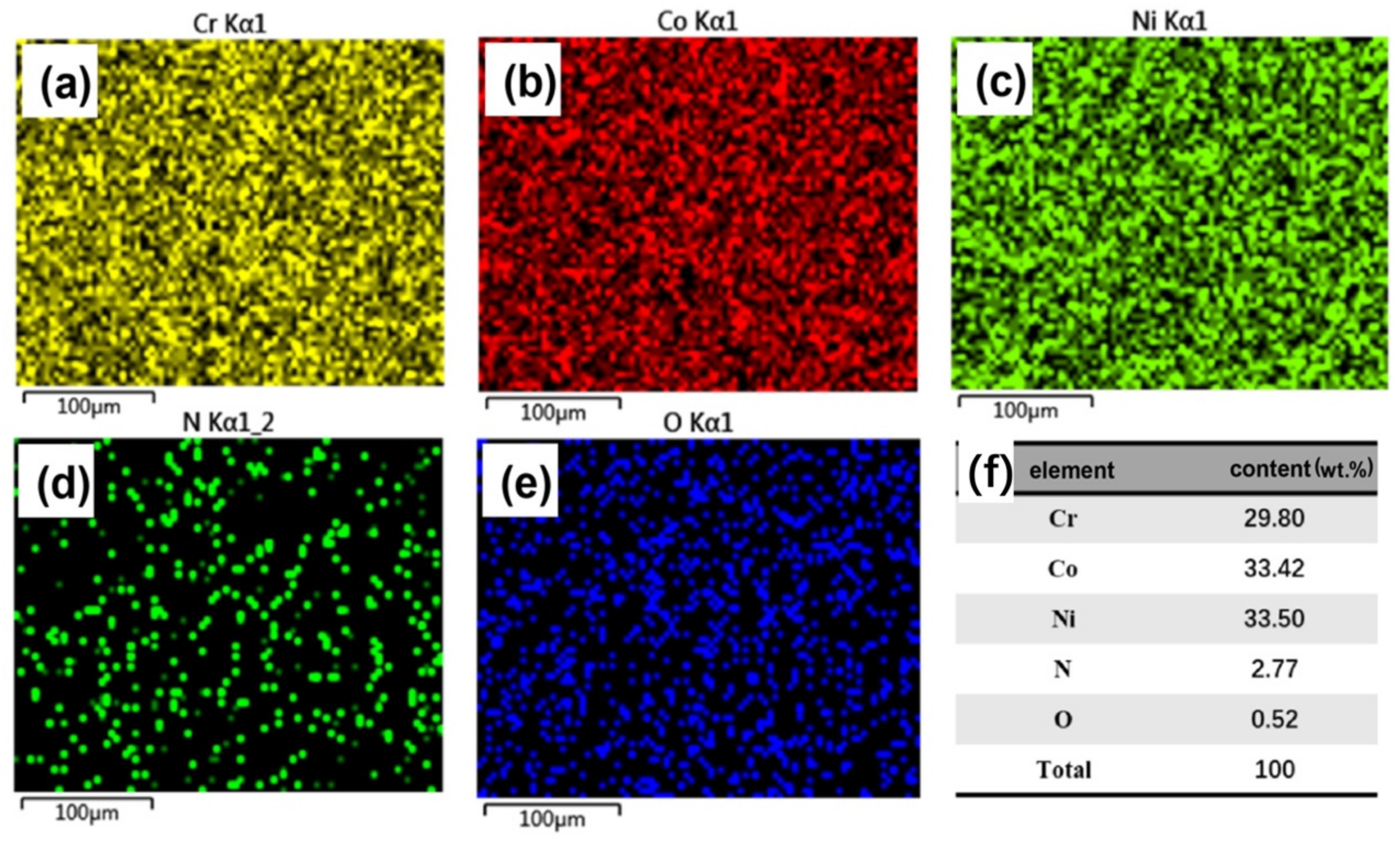
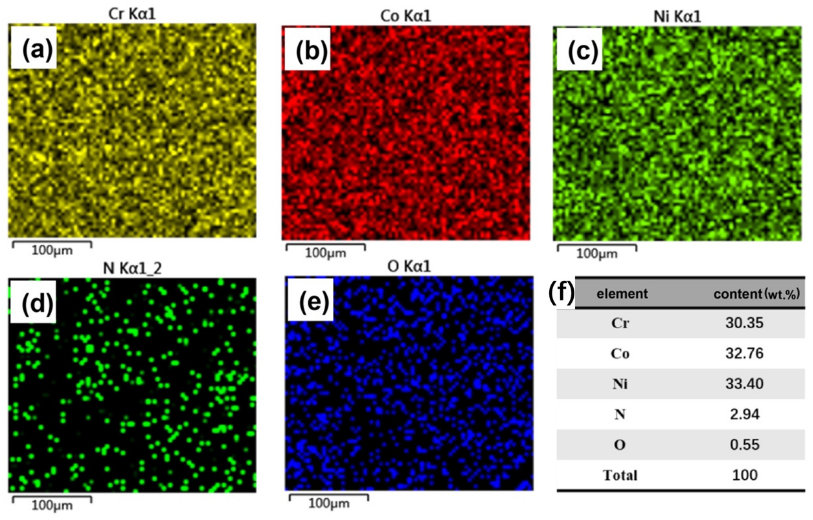
3.1.4. Chemical Elements

During the welding process, due to the effect of the welding temperature field, the microscopic elements in the joint area may react with the shielding gas and other elements in the air due to burning, segregation, etc., resulting in the change in element content and type, and then the change in the mechanical properties of the joint. In order to further study the effect of the welding process on the microstructure of the joint, EDS was used to collect the element distribution of the weld zone under different processes, and the results are shown in Figure 8, Figure 9 and Figure 10.
The three main elements of Cr, Co, and Ni in the weld zone are uniformly distributed, and no obvious elemental ablation occurs. The nitrogen content in the weld zone increased significantly under the nitrogen protection process (see Figure 9 and Figure 10). Compared with the argon protection process, the mass percentage of nitrogen in the latter two processes (Process 2 and Process 4) increased to 2.77% and 2.97%, respectively. Due to the limitation of EDS, the mode of the existing N atoms could not be obtained. Some N atoms reacted with Cr to form Cr2N compounds during the welding process, while some atoms existed in the weld area in the form of solute N. In the joints to which ultrasonic vibration is applied, more N atoms are dissolved due to the enhanced effects, such as melt pool vibration and convection. Therefore, we found N in the joints with ultrasonic assistance.

3.2. Mechanical Properties

3.2.1. Microhardness

The results of the microhardness tests on weld joints under three typical welding processes (Process 1, Process 2, Process 4) are presented in Figure 11. The hardness distribution trends in the weld joints under three different processes (Process 1, Process 2, Process 4) are essentially consistent, with the weld zone exhibiting lower hardness compared to the base material zone. This is mainly due to the fact [62] that the microstructure in the weld zone consists of coarse and large columnar grains, while the base material has been processed through rolling, annealing, and other techniques to achieve a fine and uniformly recrystallized microstructure. According to the Hall–Petch equation, smaller grain sizes result in higher strength, which is why the base material hardness (approximately 225 HV) is higher than that of the weld zone (approximately 190 HV). Near the base material side in the heat-affected zone, there is a slight increase in hardness compared to the base material. This is mainly due to the fact that the microstructure in this region undergoes recrystallization under the welding temperature [63].
Comparing the hardness values of the weld zone under the three different processes, we can observe that Process 1 (argon protection) has the lowest hardness (~185 HV). After switching the shielding gas from argon to nitrogen, the hardness value increases to around 195 HV. When 80 W ultrasonic assistance is applied in combination with nitrogen protection, the hardness of the weld zone further increases to about 200 HV. This is primarily due to the formation of small amounts of Cr2N compounds in the weld zone. These nitrides act as dispersion strengtheners within the weld zone. Additionally, some nitrogen atoms dissolve into the matrix in solute form, causing lattice distortion in the matrix and resulting in increased hardness. Furthermore, the introduction of ultrasound alters the solidification behavior of the molten pool, leading to dendrite refinement. Therefore, the combination of these factors results in the increase in hardness in the weld zone for Process 4.

3.2.2. Tensile Testing

Representative stress–strain curves of the tensile testing are shown in Figure 12a. The yield strength, tensile strength, and elongation values for the joints under different welding processes and the base material at 300 K and 77 K have been extracted in Table 2. In three different welding processes, welding joints exhibited good strength and elongation at 300 K. Both the yield and tensile strength can reach up to 75% of these of the BM. When comparing the mechanical performance of these three different welding processes, it was observed that using nitrogen as the welding shielding gas and introducing ultrasonic assistance simultaneously improved various mechanical properties of the joints, including yield strength, tensile strength, and elongation. The possible explanations are the interactions between nitrogen atoms and dislocations, the formation of chromium nitride (Cr2N) precipitates, as well as the combined effects of solid solution strengthening, precipitation strengthening, and grain refinement resulting from the incorporation of nitrogen atoms into the matrix. Mathieu Traversier et al. [64], when doping nitrogen into the as-cast CrFeMnNi medium-entropy alloy, found that the material’s strength increased with an increase in nitrogen content while maintaining elongation, mainly due to the enhancement of solid solution strengthening caused by nitrogen. Igor Moravcik et al. [54] found that doping nitrogen atoms into the CrCoNi MEA can increase lattice friction stress from 211–216 MPa to 254 MPa. Additionally, the dendrites were refined due to the ultrasonic assistance. Therefore, the enhancement of lattice friction stress by nitrogen atoms and dendrite refinement are the primary reasons for the strength improvement in ultrasonically assisted laser-welded joints using nitrogen as the shielding gas.
Compared to the room temperature mechanical properties, at low temperature (77 K), the tensile strength and elongation of the CrCoNi medium-entropy alloy joints and the base material have significantly improved. At 77 K, the tensile strength of the base metal and joints increased to 1071 MPa and 1313 MPa, respectively. For FCC materials with low stacking fault energy, such as TWIP steel and FeCoCrNiMn, twinning serves as an additional strengthening mechanism alongside dislocation slip during plastic deformation. With the decrease in temperature, both stacking fault energy and critical twinning stress decrease, making twinning more likely to occur. According to the dynamic Hall–Petch effect [65], nanoscale twins exert a pinning effect on the movement of dislocations, thereby enhancing the material’s strain hardening capability and, consequently, improving the material’s strength and toughness.
We compared our mechanical properties with other welded HEA joints in Figure 12b. The mechanical properties in the literature can be divided into two regions, i.e., low strength and ductility. In other words, the welded joints either have high ductility but with low strength, or have high strength but with low ductility. Therefore, the combination of strength and ductility is not satisfied. In our case, as shown in Figure 12b, the combination of strength and ductility is sound, implying the high-performance ability of our joints.
Figure 12. Results of the tensile testing. (a) Engineering stress–strain curves for BM and joints under different processes at room temperature (300 K) and cryogenic temperature (77 K), (b) UTS versus elongation for various joints, adapted from [51,52,53,66,67,68,69,70,71,72,73,74].
Metals 14 00971 g012
Figure 13 shows the macroscopic fracture morphology of joints under different welding processes at low and room temperatures. It is evident that the fractures occurred in the vicinity of the weld seam near the weld seam centerline. This is mainly because grain growth starts from the fusion boundaries and ends at the center of the weld seam, where the grains are the coarsest, resulting in lower strength in that region. The macroscopic morphology displays clear necking, indicating the excellent ductility of the material. By comparing (c) and (d) in Figure 13, it is observed that although the tensile specimen at 77 K exhibits a higher elongation, the degree of necking is lower than that of the tensile specimens at 300 K. This may be due to the fact that at 77 K, more deformation twins are generated during plastic deformation, which enhances strain hardening and delays necking.

3.3. Deformation Mechanisms

In order to investigate the deformation mechanisms of the joints with ultrasonic assistance at different temperatures, EBSD was used to characterize the microstructure near the surfaces fractured at 300 K and 77 K. The results are shown in Figure 14, Figure 15 and Figure 16. Figure 14 presents the EBSD results of the joints deformed at 300 K. In Figure 14a, it can be observed that the grains are elongated along the tensile direction. The red regions in Figure 14b at the locations indicated by the black arrows represent deformation twins. A zoomed view of the twinning area is shown in Figure 14c,d, in which we can see that the twins are distributed near the gain boundaries. Figure 15 shows the EBSD results of the joint fractured at 77 K. It can be observed that at 77 K, the number of twins significantly increases, with twins mainly forming within larger grains. In the early stages of deformation, dislocations begin to accumulate at grain boundaries. As strain increases, the number of dislocations gradually rises, and twinning nucleates at grain boundaries. Therefore, in Figure 14 and Figure 15, it is evident that there are more twins near the grain boundaries, making grain boundaries the primary sites for twinning nucleation. The formation of twins requires reaching a critical stress for twinning, and stress concentration is most likely to occur at grain boundaries. In materials with coarse grain structures, it is easier to form high-density dislocation substructures, which also tend to lead to stress concentration at dislocation walls, reaching the critical stress for twin formation. Consequently, coarse-grained structures are more prone to twin formation.
Figure 16 shows the Kernel Average Misorientation (KAM) maps near the fracture surfaces at 300 K and 77 K. Using KAM maps, we can calculate the dislocation density using the following equations [64,75,76]:
ρ t o t a l = θ K A M b μ n
where ρ represents the dislocation density in the statistical region, θ K A M is the KAM angle. In Figure 16, we can obtain KAM angles of 1.85° and 1.55° for 300 K and 77 K, respectively. b is the Burgers vector size, which is given as 0.2517 [77,78]; μ is the EBSD scanning step size, which is 0.5; n is the constant with a value of 2. By performing the calculations, the average dislocation densities near the fracture surfaces at 300 K and 77 K can be determined as 4.08 × 10¹³ m−2 and 3.42 × 10¹³ m−2, respectively.

4. Conclusions

In this paper, we employed ultrasonic-assisted laser welding to join CrCoNi MEA. The evolution of the microstructure, mechanical properties and deformation mechanisms were revealed via experimental methods. The main conclusions are drawn as follows:
An ultrasonic-assisted laser welding system was established, and under the condition of 80 W ultrasonic power, the weld pool exhibited improved flowability and good stability. The dendritic structure in the fusion zone of the resulting joint was refined under the influence of ultrasonic force.
EDS results indicated that nitrogen gas, as a shielding gas, effectively introduced nitrogen atoms into the fusion zone, and the content of nitrogen atoms increased under the influence of ultrasonics. The introduction of nitrogen effectively reduced the dendritic space to 58 μm and increased the hardness of the fusion zone by 10 HV. This was due to the interaction of nitrogen gas with the molten pool, resulting in the formation of Cr2N compounds. Simultaneously, some nitrogen atoms dissolved into the matrix in the form of solute, increasing the resistance to dislocation slip.
Under the combined influence of ultrasonics and nitrogen gas, the joint’s mechanical properties were significantly improved. Specifically, the tensile strength of the joint at room temperature and low temperature was 686 MPa and 1071 MPa, respectively. The elongation at room temperature and low temperature was 26.8% and 27.7%, respectively. Our joints have shown high-performance ability in terms of the combination of strength and ductility.
EBSD experimental results indicate that the deformation mechanisms of the joint at room temperature included dislocation slip and deformation twinning. At low temperature, the dislocation density decreased, while the proportion of deformation twinning significantly increased. This led to a noticeable increase in strain hardening. Therefore, although the joint had a higher elongation at low temperature, the degree of necking was lower than at room temperature.

Author Contributions

H.Z.: Investigation, experiments, analysis, and writing. S.Y.: Conception, supervision, analysis, writing and reviewing. Z.Z.: Investigation, experiments, analysis, and writing. All authors have read and agreed to the published version of the manuscript.

Funding

S. Yan would like to acknowledge the finical support from Shenzhen Science and Technology Institute (grant no. 000617, grant no. 20220810154235001, and grant no. 707-0001330542).

Data Availability Statement

The original contributions presented in the study are included in the article, further inquiries can be directed to the corresponding author.

Conflicts of Interest

The authors declare no conflicts of interest.

References

  1. Yeh, J.-W.; Chen, S.-K.; Lin, S.-J.; Gan, J.-Y.; Chin, T.-S.; Shun, T.-T.; Tsau, C.-H.; Chan, S.-Y. Nanostructured High-entropy alloys with multiple principal elements: Novel alloy design concepts and outcomes. Adv. Eng. Mater. 2004, 6, 299–303. [Google Scholar] [CrossRef]
  2. Cantor, B.; Chang, I.T.H.; Knight, P.; Vincent, A.J.B. Microstructural development in equiatomic multicomponent alloys. Mater. Sci. Eng. A 2004, 375, 213–218. [Google Scholar] [CrossRef]
  3. George, E.P.; Curtin, W.A.; Tasan, C.C. High entropy alloys: A focused review of mechanical properties and deformation mechanisms. Acta Mater. 2020, 188, 435–474. [Google Scholar] [CrossRef]
  4. Miracle, D.B.; Senkov, O.N. A critical review of high entropy alloys and related concepts. Acta Mater. 2017, 122, 448–511. [Google Scholar] [CrossRef]
  5. Gludovatz, B.; Hohenwarter, A.; Thurston, K.V.; Bei, H.; Wu, Z.; George, E.P.; Ritchie, R.O. Exceptional damage-tolerance of a medium-entropy alloy CrCoNi at cryogenic temperatures. Nat. Commun. 2016, 7, 10602. [Google Scholar] [CrossRef] [PubMed]
  6. Laplanche, G.; Kostka, A.; Reinhart, C.; Hunfeld, J.; Eggeler, G.; George, E.P. Reasons for the superior mechanical properties of medium-entropy CrCoNi compared to high-entropy CrMnFeCoNi. Acta Mater. 2017, 128, 292–303. [Google Scholar] [CrossRef]
  7. Otto, F.; Dlouhý, A.; Somsen, C.; Bei, H.; Eggeler, G.; George, E.P. The influences of temperature and microstructure on the tensile properties of a CoCrFeMnNi high-entropy alloy. Acta Mater. 2013, 61, 5743–5755. [Google Scholar] [CrossRef]
  8. Gali, A.; George, E.P. Tensile properties of high- and medium-entropy alloys. Intermetallics 2013, 39, 74–78. [Google Scholar] [CrossRef]
  9. Wu, Z.; Bei, H.; Pharr, G.M.; George, E.P. Temperature dependence of the mechanical properties of equiatomic solid solution alloys with face-centered cubic crystal structures. Acta Mater. 2014, 81, 428–441. [Google Scholar] [CrossRef]
  10. Zhang, R.; Zhao, S.; Ding, J.; Chong, Y.; Jia, T.; Ophus, C.; Asta, M.; Ritchie, R.O.; Minor, A.M. Short-range order and its impact on the CrCoNi medium-entropy alloy. Nature 2020, 581, 283–287. [Google Scholar] [CrossRef]
  11. Yan, S.; Chen, H.; Zhu, Z.; Gou, G. Hybrid laser-Metal Inert Gas welding of Al–Mg–Si alloy joints: Microstructure and mechanical properties. Mater. Des. 2014, 61, 160–167. [Google Scholar] [CrossRef]
  12. Yan, S.; Nie, Y.; Zhu, Z.; Chen, H.; Gou, G.; Yu, J.; Wang, G. Characteristics of microstructure and fatigue resistance of hybrid fiber laser-MIG welded Al–Mg alloy joints. Appl. Surf. Sci. 2014, 298, 12–18. [Google Scholar] [CrossRef]
  13. Yan, S.; He, X.; Krüger, M.; Li, Y.; Jia, Q. Additive manufacturing of a new non-equiatomic high-entropy alloy with exceptional strength-ductility synergy via in-situ alloying. Mater. Des. 2024, 238, 112676. [Google Scholar] [CrossRef]
  14. Rackwitz, J.; Yu, Q.; Yang, Y.; Laplanche, G.; George, E.P.; Minor, A.M.; Ritchie, R.O. Effects of cryogenic temperature and grain size on fatigue-crack propagation in the medium-entropy CrCoNi alloy. Acta Mater. 2020, 200, 351–365. [Google Scholar] [CrossRef]
  15. Yan, S.; Zhou, H.; Zhu, Z.; Fu, Y.; Tian, J. High strength-ductility synergy in a laser welded dissimilar joint of CrCoNi medium-entropy alloy and stainless steel. Mater. Sci. Eng. A 2022, 840, 142854. [Google Scholar] [CrossRef]
  16. Hao, X.; Dong, H.; Li, P.; Xia, Y. Dissimilar joining of TC4 alloy to ST16 steel by GTAW. J. Manuf. Process. 2019, 37, 413–417. [Google Scholar] [CrossRef]
  17. Lv, S.; Cui, Q.; Huang, Y.; Jing, X. Influence of Zr addition on TIG welding–brazing of Ti–6Al–4V toAl5A06. Mater. Sci. Eng. A 2013, 568, 150–154. [Google Scholar] [CrossRef]
  18. Abed, H.; Malek Ghaini, F.; Shahverdi, H.R. Characterization of Fe49Cr18Mo7B16C4Nb6 high-entropy hardfacing layers produced by gas tungsten arc welding (GTAW) process. Surf. Coat. Technol. 2018, 352, 360–369. [Google Scholar] [CrossRef]
  19. Tavoosi, M.; Arjmand, S.; Adelimoghaddam, B. Surface alloying of commercially pure titanium with aluminium and nitrogen using GTAW processing. Surf. Coat. Technol. 2017, 311, 314–320. [Google Scholar] [CrossRef]
  20. Xia, C.; Pan, Z.; Polden, J.; Li, H.; Xu, Y.; Chen, S.; Zhang, Y. A review on wire arc additive manufacturing: Monitoring, control and a framework of automated system. J. Manuf. Syst. 2020, 57, 31–45. [Google Scholar] [CrossRef]
  21. Sokkalingam, R.; Mishra, S.; Cheethirala, S.R.; Muthupandi, V.; Sivaprasad, K. Enhanced Relative Slip Distance in Gas-Tungsten-Arc-Welded Al0.5CoCrFeNi High-Entropy Alloy. Metall. Mater. Trans. A 2017, 48, 3630–3634. [Google Scholar] [CrossRef]
  22. Martin, A.C.; Fink, C. Initial weldability study on Al0.5CrCoCu0.1FeNi high-entropy alloy. Weld. World 2019, 63, 739–750. [Google Scholar] [CrossRef]
  23. Shinde, G.; Gajghate, S.; Dabeer, P.S.; Seemikeri, C.Y. Low Cost Friction Stir Welding: A Review. Mater. Today Proc. 2017, 4, 8901–8910. [Google Scholar] [CrossRef]
  24. Singh, K.; Singh, G.; Singh, H. Review on friction stir welding of magnesium alloys. J. Magnes. Alloys 2018, 6, 399–416. [Google Scholar] [CrossRef]
  25. Panaskar, N.; Terkar, R. A Review on Recent Advances in Friction Stir Lap Welding of Aluminium and Copper. Mater. Today Proc. 2017, 4, 8387–8393. [Google Scholar] [CrossRef]
  26. Wang, X.-N.; Chen, C.-J.; Wang, H.-S.; Zhang, S.-H.; Zhang, M.; Luo, X. Microstructure formation and precipitation in laser welding of microalloyed C–Mn steel. J. Mater. Process. Technol. 2015, 226, 106–114. [Google Scholar] [CrossRef]
  27. Sun, Q.; Di, H.-S.; Li, J.-C.; Wang, X.-N. Effect of pulse frequency on microstructure and properties of welded joints for dual phase steel by pulsed laser welding. Mater. Des. 2016, 105, 201–211. [Google Scholar] [CrossRef]
  28. Qi, X.; Di, H.; Wang, X.; Liu, Z.; Misra, R.D.K.; Huan, P.; Gao, Y. Effect of secondary peak temperature on microstructure and toughness in ICCGHAZ of laser-arc hybrid welded X100 pipeline steel joints. J. Mater. Res. Technol. 2020, 9, 7838–7849. [Google Scholar] [CrossRef]
  29. Wang, X.; Zhang, Z.; Hu, Z.; Sun, Q.; Di, H.; Lv, F.; Sun, L. Effect of Ni foil thickness on the microstructure of fusion zone during PHS laser welding. Opt. Laser Technol. 2020, 125, 106014. [Google Scholar] [CrossRef]
  30. Errico, V.; Campanelli, S.L.; Angelastro, A.; Mazzarisi, M.; Casalino, G. On the feasibility of AISI 304 stainless steel laser welding with metal powder. J. Manuf. Process. 2020, 56, 96–105. [Google Scholar] [CrossRef]
  31. Dai, W.; Wenjun, S.; Xin, J.; Wang, S.; Fang, C.; Wei, J.; Song, Y. Weldability and mechanical properties of IC10 single crystal and GH3039 superalloy dissimilar laser beam welding joint. Mater. Sci. Eng. A 2020, 791, 139797. [Google Scholar] [CrossRef]
  32. Chen, X.; Wang, X.; Liu, Z.; Hu, Z.; Huan, P.; Yan, Q.; Hiromi, N. Effect of Cu content on microstructure transformation and mechanical properties of Fe-Al dissimilar laser welded joints. Opt. Laser Technol. 2020, 126, 106078. [Google Scholar] [CrossRef]
  33. Chen, X.; Lei, Z.; Chen, Y.; Han, Y.; Jiang, M.; Tian, Z.; Bi, J.; Lin, S. Microstructure and tensile properties of Ti/Al dissimilar joint by laser welding-brazing at subatmospheric pressure. J. Manuf. Process. 2020, 56, 19–27. [Google Scholar] [CrossRef]
  34. Malikov, A.; Vitoshkin, I.; Orishich, A.; Filippov, A.; Karpov, E. Microstructure and mechanical properties of laser welded joints of Al-Cu-Li and Ti-Al-V alloys. J. Manuf. Process. 2020, 53, 201–212. [Google Scholar] [CrossRef]
  35. Gu, Z.; Mao, P.; Gou, Y.; Chao, Y.; Xi, S. Microstructure and properties of MgMoNbFeTi2Yx high entropy alloy coatings by laser cladding. Surf. Coat. Technol. 2020, 402, 126303. [Google Scholar] [CrossRef]
  36. Panina, E.; Yurchenko, N.; Zherebtsov, S.; Stepanov, N.; Salishchev, G.; Ventzke, V.; Dinse, R.; Kashaev, N. Laser Beam Welding of a Low Density Refractory High Entropy Alloy. Metals 2018, 9, 1351. [Google Scholar] [CrossRef]
  37. Nam, H.; Park, C.; Kim, C.; Kang, N. Effect of post weld heat treatment on weldability of high entropy alloy welds. Sci. Technol. Weld. Join. 2017, 23, 420–427. [Google Scholar] [CrossRef]
  38. Chen, G.; Yin, Q.; Zhang, G.; Zhang, B. Underlying causes of poor mechanical properties of aluminum-lithium alloy electron beam welded joints. J. Manuf. Process. 2020, 50, 216–223. [Google Scholar] [CrossRef]
  39. Sun, W.; Wang, S.; Xin, J.; Tan, G.; Hong, M.; Wu, M.; Ke, L. Microstructure and mechanical properties of the IC10/GH3039 dissimilar electron beam welded joint. Vacuum 2020, 181, 109592. [Google Scholar] [CrossRef]
  40. Vijayanand, D.; Vanaja, J.; Das, C.; Mariappan, K.; Thakur, A.; Hussain, S.; Prasad Reddy, G.V.; Sasikala, G.; Albert, S. An Investigation of Microstructural Evolution in Electron Beam Welded RAFM steel and 316LN SS dissimilar joint under creep loading conditions. Mater. Sci. Eng. A 2018, 742, 432–441. [Google Scholar] [CrossRef]
  41. Chen, G.; Liu, J.; Shu, X.; Zhang, B.; Feng, J. Study on microstructure and performance of molybdenum joint welded by electron beam. Vacuum 2018, 154, 1–5. [Google Scholar] [CrossRef]
  42. Chen, G.; Liu, J.; Shu, X.; Gu, H.; Zhang, B.; Feng, J. Beam scanning effect on properties optimization of thick-plate 2A12 aluminum alloy electron-beam welding joints. Mater. Sci. Eng. A 2019, 744, 583–592. [Google Scholar] [CrossRef]
  43. Sang, S.; Li, D.; Wang, C.; Ding, L.; Tang, Y.; Xiong, Q. Microstructure and mechanical properties of electron beam welded joints of tantalum and GH3128. Mater. Sci. Eng. A 2019, 768, 138431. [Google Scholar] [CrossRef]
  44. Gao, F.; Yu, W.; Song, D.; Gao, Q.; Guo, L.; Liao, Z. Fracture toughness of TA31 titanium alloy joints welded by electron beam welding under constrained condition. Mater. Sci. Eng. A 2020, 772, 138612. [Google Scholar] [CrossRef]
  45. Yang, Z.W.; Wang, C.L.; Han, Y.; Zhao, Y.T.; Wang, Y.; Wang, D.P. Design of reinforced interfacial structure in brazed joints of C/C composites and Nb by pre-oxidation surface treatment combined with in situ growth of CNTs. Carbon 2019, 143, 494–506. [Google Scholar] [CrossRef]
  46. Wang, Z.; De-Chun, B.; Cao, P.J.; Liang, J. Effect of Boron-Doping on Morphology and Microstructure of Carbon Nanotube. J. Northeast. Univ. 2005, 26, 582–584. [Google Scholar]
  47. Chang, S.-H.; Wu, S.-K.; Kuo, C. Effect of reinforced multiwall carbon nanotubes on the damping characteristics of Sn-Ag-Cu lead-free solder. Mater. Lett. 2020, 276, 128196. [Google Scholar] [CrossRef]
  48. Luo, C.; Qiu, X.; Ruan, Y.; Lu, Y.; Xing, F. Effect of Bi addition on the corrosion resistance and mechanical properties of sintered NdFeB permanent magnet/steel soldered joints. Mater. Sci. Eng. A 2020, 792, 139832. [Google Scholar] [CrossRef]
  49. Lin, J.; Wang, J.; Baoxin, H.; Zhengxiang, Z.; Qiang, Z. Carbon nanotubes-reinforced Ni foam interlayer for brazing SiO2-BN with Ti6A14V alloy using TiZrNiCu brazing alloy. Ceram. Int. 2018, 44, 3684–3691. [Google Scholar]
  50. Li, Y.; Chen, C.; Yi, R.; Ouyang, Y. Review: Special brazing and soldering. J. Manuf. Process. 2020, 60, 608–635. [Google Scholar] [CrossRef]
  51. Peng, H.; Yi, Y.; Fang, W.; Hu, L.; Baker, I.; Li, L.; Luo, B. Optimization of the microstructure and mechanical properties of electron beam welded high-strength medium-entropy alloy (NiCoCr)94Al3Ti3. Intermetallics 2022, 141, 107439. [Google Scholar] [CrossRef]
  52. Li, N.; Wang, R.X.; Zhao, H.B.; Tang, Y.; Xue, P.; Ni, D.R.; Xiao, B.L.; Ma, Z.Y.; Wu, L.H. Microstructure and mechanical properties of electron beam welded TiZrNbTa refractory high entropy alloy. Mater. Today Commun. 2022, 32, 103847. [Google Scholar] [CrossRef]
  53. Chen, C.; Sun, G.; Sun, X.; Zhao, X.; Wang, S. AC/DC mixed gas tungsten arc welding of a (FeCoNi)96Al4 high-entropy alloy. J. Mater. Res. Technol. 2024, 30, 1531–1538. [Google Scholar] [CrossRef]
  54. Moravcik, I.; Hadraba, H.; Li, L.; Dlouhy, I.; Li, Z. Yield strength increase of a CoCrNi medium entropy alloy by interstitial nitrogen doping at maintained ductility. Scr. Mater. 2020, 178, 391–397. [Google Scholar] [CrossRef]
  55. Yan, S.; Zhou, H.; Xing, B.; Zhang, S.; Li, L.; Qin, Q.H. Crystal plasticity in fusion zone of a hybrid laser welded Al alloys joint: From nanoscale to macroscale. Mater. Des. 2018, 160, 313–324. [Google Scholar] [CrossRef]
  56. Yan, S.; Qin, Q.H.; Chen, H.; Zhong, Z. Hybrid laser welding of dissimilar aluminum alloys: Welding processing, microstructure, properties and modelling. J. Manuf. Process. 2020, 56, 295–305. [Google Scholar] [CrossRef]
  57. Yan, S.; Ma, C.; Chen, H. Modifying microstructures and mechanical properties of laser-arc welded joints of dissimilar advanced aluminum alloys. Mater. Charact. 2020, 164, 110331. [Google Scholar] [CrossRef]
  58. Talebi, M.; Setareh, M.; Saffar-Avval, M.; Hosseini Abardeh, R. Numerical investigation of natural convection heat transfer in a cylindrical enclosure due to ultrasonic vibrations. Ultrasonics 2017, 76, 52–62. [Google Scholar] [CrossRef]
  59. Kim, H.-Y.; Kim, Y.G.; Kang, B.H. Enhancement of natural convection and pool boiling heat transfer via ultrasonic vibration. Int. J. Heat Mass Transf. 2004, 47, 2831–2840. [Google Scholar] [CrossRef]
  60. Drezet, J.-M.; Pellerin, S.; Bezençon, C.; Mokadem, S. Modelling Marangoni convection in laser heat treatment. J. Phys. IV (Proc.) 2004, 120, 299–306. [Google Scholar] [CrossRef]
  61. Wu, Z.; David, S.A.; Feng, Z.; Bei, H. Weldability of a high entropy CrMnFeCoNi alloy. Scr. Mater. 2016, 124, 81–85. [Google Scholar] [CrossRef]
  62. Yan, S.; Xing, B.; Zhou, H.; Xiao, Y.; Qin, Q.-H.; Chen, H. Effect of filling materials on the microstructure and properties of hybrid laser welded Al-Mg-Si alloys joints. Mater. Charact. 2018, 144, 205–218. [Google Scholar] [CrossRef]
  63. Laplanche, G.; Kostka, A.; Horst, O.M.; Eggeler, G.; George, E.P. Microstructure evolution and critical stress for twinning in the CrMnFeCoNi high-entropy alloy. Acta Mater. 2016, 118, 152–163. [Google Scholar] [CrossRef]
  64. Traversier, M.; Mestre-Rinn, P.; Peillon, N.; Rigal, E.; Boulnat, X.; Tancret, F.; Dhers, J.; Fraczkiewicz, A. Nitrogen-induced hardening in an austenitic CrFeMnNi high-entropy alloy (HEA). Mater. Sci. Eng. A 2021, 804, 140725. [Google Scholar] [CrossRef]
  65. Yoshida, S.; Ikeuchi, T.; Bhattacharjee, T.; Bai, Y.; Shibata, A.; Tsuji, N. Effect of elemental combination on friction stress and Hall-Petch relationship in face-centered cubic high/medium entropy alloys. Acta Mater. 2019, 171, 201–215. [Google Scholar] [CrossRef]
  66. Lopes, J.G.; Agrawal, P.; Shen, J.; Schell, N.; Mishra, R.S.; Oliveira, J.P. Evolution of microstructure and mechanical properties in gas tungsten arc welded dual-phase Fe50Mn30Co10Cr10 high entropy alloy. Mater. Sci. Eng. A 2023, 878, 145233. [Google Scholar] [CrossRef]
  67. Oliveira, J.P.; Shamsolhodaei, A.; Shen, J.; Lopes, J.G.; Gonçalves, R.M.; Ferraz, M.d.B.; Piçarra, L.; Zeng, Z.; Schell, N.; Zhou, N.; et al. Improving the ductility in laser welded joints of CoCrFeMnNi high entropy alloy to 316 stainless steel. Mater. Des. 2022, 219, 110717. [Google Scholar] [CrossRef]
  68. Sang, Y.; Li, D.; Deng, W. Electron beam weldability of TiZrNbTa refractory high-entropy alloy and TC4 titanium alloy. Mater. Today Commun. 2024, 38, 107890. [Google Scholar] [CrossRef]
  69. Deng, W.; Li, D.; Yang, B.; Wu, H.; Yu, S. Microstructure and mechanical properties of electron beam welded joints of GH3128 and CoCrFeNi high-entropy alloy. Mater. Today Commun. 2024, 39, 108898. [Google Scholar] [CrossRef]
  70. Palguna, Y.; Sairam, K.; Kannan, A.R.; Shanmugam, N.S.; Korla, R.; Oliveira, J.P. Effect of post weld heat treatment on the microstructure and mechanical properties of gas tungsten arc welded Al0.3CoCrFeNi high entropy alloy. Scr. Mater. 2024, 241, 115887. [Google Scholar] [CrossRef]
  71. Xin, J.; Wang, W.; Yang, X.; Boubeche, M.; Wang, S.; Zhang, H.; Huang, C.; Li, Y.; Lyu, B.; Shen, F.; et al. Dissimilar laser welding of CrMnFeCoNi high entropy alloy and 316LN stainless steel for cryogenic application. J. Mater. Sci. Technol. 2023, 163, 158–167. [Google Scholar] [CrossRef]
  72. Wu, S.C.; Yu, C.; Yu, P.S.; Buffière, J.Y.; Helfen, L.; Fu, Y.N. Corner fatigue cracking behavior of hybrid laser AA7020 welds by synchrotron X-ray computed microtomography. Mater. Sci. Eng. A 2016, 651, 604–614. [Google Scholar] [CrossRef]
  73. Kashaev, N.; Ventzke, V.; Petrov, N.; Horstmann, M.; Zherebtsov, S.; Shaysultanov, D.; Sanin, V.; Stepanov, N. Fatigue behaviour of a laser beam welded CoCrFeNiMn-type high entropy alloy. Mater. Sci. Eng. A 2019, 766, 138358. [Google Scholar] [CrossRef]
  74. Zhu, Z.; Yan, S.; Chen, H.; Gou, G. Unprecedented combination of strength and ductility in laser welded NiCoCr medium entropy alloy joints. Mater. Sci. Eng. A 2021, 803, 140501. [Google Scholar] [CrossRef]
  75. Kubin, L.P.; Mortensen, A. Geometrically necessary dislocations and strain-gradient plasticity: A few critical issues. Scr. Mater. 2003, 48, 119–125. [Google Scholar] [CrossRef]
  76. Eftekharimilani, P.; van der Aa, E.M.; Hermans, M.J.M.; Richardson, I.M. Microstructural characterisation of double pulse resistance spot welded advanced high strength steel. Sci. Technol. Weld. Join. 2017, 22, 545–554. [Google Scholar] [CrossRef]
  77. Yan, S.; Nie, Y.; Paradowska, A. Effect of specimen size and crystallographic orientation on the nano/microscale mechanical properties and deformation behavior of CrCoNi medium-entropy alloy. Mater. Des. 2023, 235, 112387. [Google Scholar] [CrossRef]
  78. Li, H.; Li, Y.; Nie, Y.; Yan, S. Small-scale mechanical properties and deformation mechanisms of a laser welded CrCoNi medium-entropy alloy joint. Mater. Sci. Eng. A 2022, 855, 143959. [Google Scholar] [CrossRef]
Figure 1. Microstructure of the base material: (a) inverse pole figure (IPF map); (b) grain boundary and twin boundary distribution (red for twin boundaries, black for high-angle grain boundaries).
Metals 14 00971 g001
Figure 2. Schematic diagram of the ultrasonic-assisted laser welding system.
Metals 14 00971 g002
Figure 3. Macroscopic appearance of joints under different welding processes: (a) argon shielding, laser welded joint without ultrasonic assistance; (b) nitrogen shielding, laser welded joint without ultrasonic assistance; (c) nitrogen shielding, laser welded joint with 40 W ultrasonic assistance; (d) nitrogen shielding, laser welded joint with 80 W ultrasonic assistance.
Metals 14 00971 g003
Figure 4. Top and bottom width of the welding area under different welding processes.
Metals 14 00971 g004
Figure 5. The dendrites under different welding conditions. (a) Argon-protected laser welding joint, (b) nitrogen-protected laser welding joint, (c) nitrogen-protected laser welding with 40 W ultrasonic assistance, (d) nitrogen-protected laser welding with 80 W ultrasonic assistance.
Metals 14 00971 g005
Figure 6. Space between dendrites under different welding processes.
Metals 14 00971 g006
Figure 7. EBSD results of heat-affected zone and weld zone under different processes (IPF map). (a) argon protection, no ultrasound-assisted; (b) nitrogen protection, no ultrasound-assisted; (c) nitrogen protection, 80 W ultrasound-assisted.
Metals 14 00971 g007
Figure 8. Elemental surface distribution and content in weld seam zone for Process 1: (a) scanning area in the weld seam zone, (b) Cr element, (c) Co element, (d) Ni element, (e) O element, (f) elemental content.
Metals 14 00971 g008
Figure 9. Elemental surface distribution and content in weld seam zone for Process 2: (a) Cr element, (b) Co element, (c) Ni element, (d) N element, (e) O element, (f) elemental content.
Metals 14 00971 g009
Figure 10. Elemental surface distribution and content in weld seam zone for Process 4: (a) Cr element, (b) Co element, (c) Ni element, (d) N element, (e) O element, (f) elemental content.
Metals 14 00971 g010
Figure 11. Microhardness of the joints under three different processes.
Metals 14 00971 g011
Figure 13. Macroscopic fracture morphology of joints under different welding processes: (a) argon shielding tested at 300 K, (b) nitrogen shielding tested at 300 K, (c) nitrogen shielding, +80 W ultrasonic-assisted and tested at 300 K, (d) nitrogen shielding, +80 W ultrasonic-assisted and tested at 77 K.
Metals 14 00971 g013
Figure 14. The EBSD results of the joint fractured at 300 K, (a) IPF and grain boundary maps, (b) deformation twinning (indicated by arrows) and band contrast distribution map, (c) IPF map at the location marked with a square, (d) deformation twinning and band contrast map at the location marked with a square.
Metals 14 00971 g014
Figure 15. The EBSD results of the joint fractured at 77 K, (a) IPF and grain boundary maps, (b) deformation twinning (indicated by arrows) and band contrast distribution map, (c) IPF map at the location marked with a square, (d) deformation twinning and band contrast map at the location marked with a square.
Metals 14 00971 g015
Figure 16. KAM maps and local orientation difference statistical data of the CrCoNi joint fractured at different temperatures, (a) KAM map and local orientation difference statistical data at 300 K; (b) KAM map and local orientation difference statistical data at 77 K.
Metals 14 00971 g016
Table 1. Process parameters of laser welding.
Process
Number
Welding MethodPower
(kW)
Welding Speed
(mm/s)
Laser Inclination Angle (°)Gas Flow
(L·min−1)
Shielding Gas
Process 1Laser welding1.8101030Ar2
Process 2Laser welding1.8101030N2
Process 3Ultrasonic (40 W) +
Laser welding
1.8101030N2
Process 4Ultrasonic (80 W) +
Laser welding
1.8101030N2
Table 2. Mechanical properties of CrCoNi high-entropy alloy base material and joints at room temperature (300 K) and low temperature (77 K).
MaterialYield Strength (MPa)Tensile Strength (MPa)Uniform Elongation (%)
300 K77 K300 K77 K300 K77 K
Joint (Ar)405.6 ± 9/662 ± 2/19.6/
Joint (N2)413.7 ± 10/678.9 ± 8/22.7/
Joint (ultrasonic + N2)421 ± 6681.17 ± 14686 ± 101071 ± 1926.828 ± 1
Base material527 ± 9856.2 ± 33886 ± 191313 ± 2856.4 ± 369 ± 1
Disclaimer/Publisher’s Note: The statements, opinions and data contained in all publications are solely those of the individual author(s) and contributor(s) and not of MDPI and/or the editor(s). MDPI and/or the editor(s) disclaim responsibility for any injury to people or property resulting from any ideas, methods, instructions or products referred to in the content.

