Article

Casting Process and Quality Control Analysis of Zr705C Zirconium Alloy

by
Youwei Zhang
1,2,3,*,
Zhongde Shan
1,4,*,
Yong Zang
2,
Dehua Jin
3,
Chunling Bao
3,
Xiao Liang
4 and
Qian Yao
3
1
China Academy of Machinery Science and Technology Group Co., Ltd., Beijing 100044, China
2
School of Materials Science and Engineering, University of Science and Technology Beijing, Beijing 100083, China
3
China Academy of Machinery Shenyang Research Institute of Foundry Co., Ltd., Shenyang 110022, China
4
School of Mechanical and Electrical Engineering, Nanjing University of Aeronautics and Astronautics, Nanjing 210016, China
*
Authors to whom correspondence should be addressed.
Metals 2025, 15(4), 417; https://doi.org/10.3390/met15040417
Submission received: 27 February 2025 / Revised: 25 March 2025 / Accepted: 3 April 2025 / Published: 7 April 2025

Abstract

:
Basic research on and the industrial development of zirconium alloys in China started relatively late, with insufficient domestic production capacity for zirconium alloy castings; especially for large-sized zirconium alloy castings, there is little production experience and significant challenges in quality control. Therefore, the production and research and development of zirconium alloy castings have received widespread attention from academia and industrial production sectors. This article analyzes the production status of domestic zirconium alloy castings, examines the casting process characteristics of valve body castings, and optimizes the casting process based on ProCAST simulation analysis results, using a lost foam precision casting process to cast a large-sized, high-pressure zirconium alloy casting for chemical use. The phase composition and microstructure were tested and analyzed, and the results showed the following: there is a certain thickness of the diffusion contamination layer on the surface of the castings. Finally, key points regarding zirconium alloy casting surface quality control and welding quality control were proposed, effectively improving the quality of the castings.

1. Introduction

Zirconium and zirconium alloys have significant advantages due to their low thermal neutron absorption cross-section, small density and thermal expansion coefficient, and good mechanical properties and corrosion resistance in harsh environments of high temperature and pressure [1], making them widely used in the nuclear and chemical industries. The main difference between the two lies in their content of Hf; zirconium with a Hf content below 0.01% is classified as nuclear-grade zirconium [2,3], while that with a Hf content around 4.5% is classified as industrial-grade zirconium [4,5]. Industrial-grade zirconium alloys are mainly used as corrosion-resistant structural materials and components in fields such as petrochemicals and pharmaceuticals. In the chemical industry, they are primarily used in heat exchangers, extraction towers, reaction vessels, pumps, valves, and pipelines for corrosive media [6]. According to the ASTM B752 and YS/T 853 standards, the main grades of industrial zirconium materials are Zr702C (Zr-3) and Zr705C (Zr-5). Among them, Zr702C is unalloyed industrial pure zirconium, while Zr705C is a Zr-Nb alloy, which adds 2.0 to 3.0% Nb based on Zr702C [7,8]. Therefore, Zr705C has a better corrosion resistance and mechanical strength than Zr702C [9]. This material is widely used under conditions requiring high structural strength [10]. Currently, the application of zirconium alloys in the chemical industry is mainly in the form of castings, forgings, and pipes [11,12]. Most of the zirconium alloy castings used in China’s nuclear industry equipment rely on imports, while domestically produced zirconium alloy castings are mainly applied in the chemical field, focusing on small-sized pump bodies, valve bodies, and other castings, with a lack of casting experience for larger high-pressure zirconium alloy castings. Therefore, important zirconium alloy castings for chemical use still rely on imports [13]. Currently, the main companies producing industrial-grade zirconium alloy castings abroad include ATI Wah Chang (a subsidiary of Allegheny Technologies Inc., Dallas, Texas, USA) in the United States; Cameco in Saskatoon, Saskatchewan, Canada; CEZUS (a subsidiary of AREVA) in Paris, France; and Sandvik in Sandviken, Sweden. Domestically, companies producing industrial-grade zirconium alloy castings include China Academy of Machinery Shenyang Research Institute of Foundry Co., Ltd., Shen Yang, China; Luoyang Sunrui Titanium Precision Casting Co., Ltd., Luo Yang, China; State nuclear Bao tai Zirconium Industry Co., Ltd., Boji, China; and Xi’an Pump and Valve Plant Co., Ltd., Xi’an, China [14,15].
There are few reports on zirconium alloy castings both domestically and internationally, and research on casting processes is also limited. In actual production, the selection of process methods is usually the same as that for titanium alloy castings. Based on the domestic level of zirconium alloy casting technology, this article takes a typical zirconium alloy valve body casting used in the chemical industry as an example, using the investment casting process with investment casting molds for production. Through simulation analysis, process design and optimization are carried out, and combined with the subsequent production process of the castings, the key points of quality control for important procedures in the casting production process are analyzed, providing certain technical support for the localization and large-scale application of zirconium alloy castings in the chemical industry.

2. Zirconium Alloy Processing Technology

Zirconium is a reactive metal, belonging to group IVB elements together with titanium and hafnium, with a density of 6.49 g/cm3, a melting point of 1852 °C, and a boiling point as high as 4377 °C. It can react with many substances, so zirconium and zirconium alloys need to be melted under vacuum or inert gas protection, and the chemical stability of the casting material is required to be very high [7].

2.1. Melting Method

Zirconium has the same melting characteristics as titanium and hafnium, and all of them are reactive metals at high temperatures. At the same time, these alloys are all classified as refractory metals, with high melting points and poor fluidity, which undoubtedly requires extremely high standards for melting technology. Therefore, zirconium alloys and titanium alloys, as well as hafnium alloys, often use similar melting preparation techniques [16]. Currently, the most commonly used technologies in the production of zirconium alloy castings are vacuum consumable electrode arc melting technology and vacuum induction melting technology [17].

2.2. Molding Process

Currently, there are two main forming processes widely used for zirconium alloy castings: the lost wax precision casting process and the machining graphite mold process [18]. In addition, there is sand casting, which has very few reported applications. Given the differences in the refractoriness and thermal properties of molding materials, the surface quality of castings produced by lost wax precision casting is superior to that of graphite mold casting, but the production cost is higher, and it is mainly suitable for medium and small castings [19,20]. In this experiment, the valve body casting is small in size and complex in structure, and the dimensional accuracy is required to be high. So, we used the investment precision casting process to make the molds required for the valve body castings.

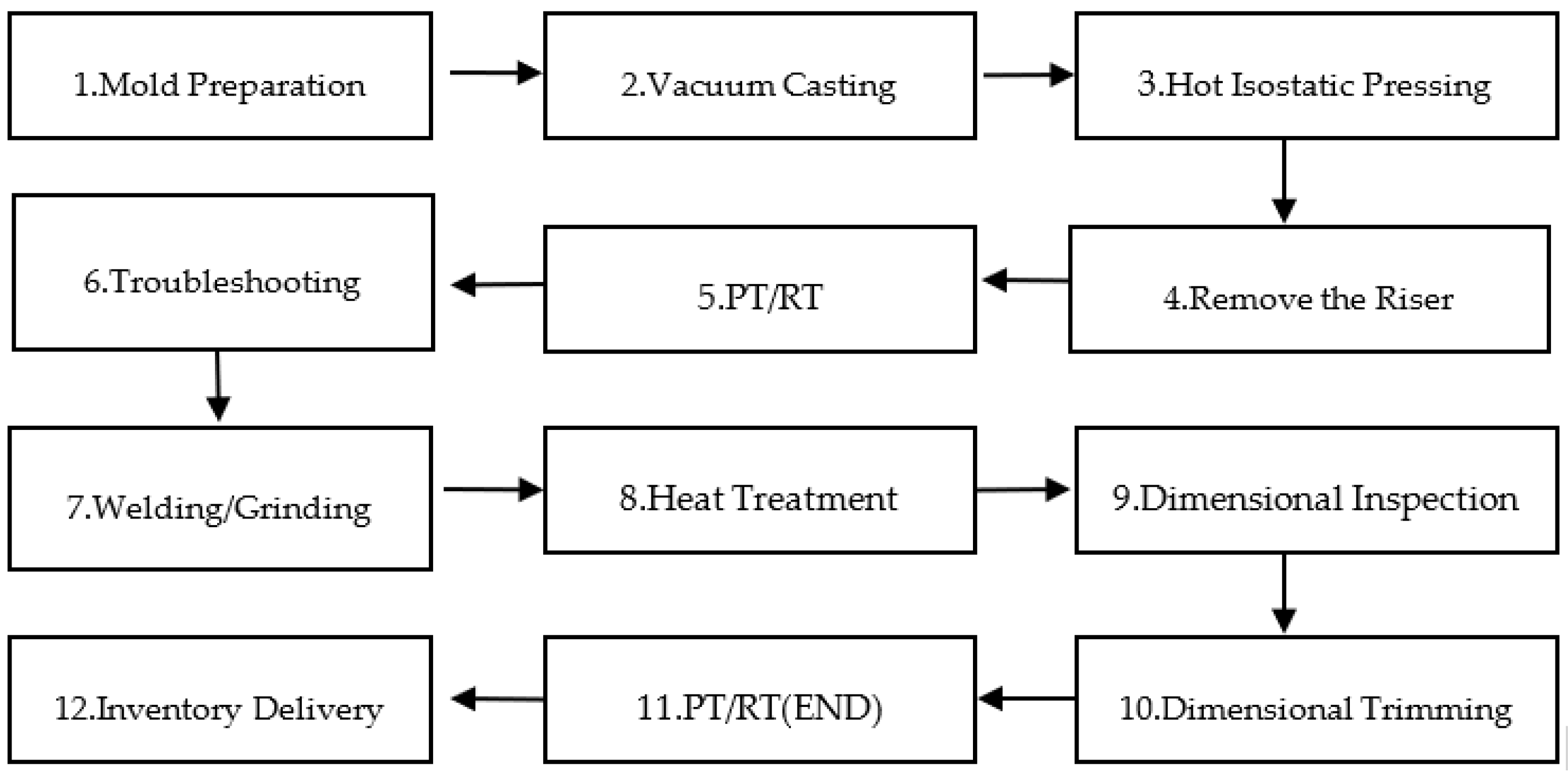
2.3. Casting Process

The casting process of zirconium alloys is similar to that of titanium alloys, but zirconium alloys are more reactive than titanium alloys at high temperatures, requiring stricter process control during production. Based on the melting and casting characteristics of zirconium alloys, this article mainly outlines the casting production process of zirconium alloys from three main aspects: mold making, melting and pouring, and the post-processing of castings, as shown in Figure 1.

2.4. Welding Process

Surface and internal defects are inevitable in newly castings, and to meet product delivery requirements, we usually adopt welding methods. Among them, the supplementary welding of castings is an effective means to ensure that the quality meets the requirements. However, various problems may also arise during the supplementary welding process. Therefore, this article summarizes the welding methods of castings and the details that should be paid attention to, for reference in subsequent production research.
The welding methods currently used for zirconium alloys mainly include tungsten inert gas welding (TIG), vacuum electron beam welding (HV-EBW), and plasma arc welding (PAW) [21]. The thermal conductivity of zirconium alloys is slightly greater than that of titanium but much less than that of iron, making it a material with relatively poor thermal conductivity [22]. At high temperatures, it easily reacts with H2, O2, and N2. It forms ZrH2 with hydrogen at 200 °C, and at about 315 °C, zirconium alloys absorb hydrogen and cause hydrogen embrittlement. They react with oxygen at 300 °C to produce ZrO3, and above 550 °C, they react with oxygen in the air to form a brittle oxide layer. Above 700 °C, zirconium absorbs oxygen, causing the severe embrittlement of the material; at 600 °C, zirconium absorbs nitrogen to form ZrN. To avoid adverse effects caused by prolonged high temperatures in the welding area, the welding parameters such as welding speed, current, and vacuum degree should be strictly controlled [23,24,25].
The thermal expansion coefficient of zirconium is smaller than that of titanium and much lower than that of other materials, resulting in less deformation during welding, which reduces stress and is beneficial for welding. Zirconium has a very low tendency to produce cracks during welding, and various welding methods can be used, among which argon arc welding is a more economical method. However, due to the strong chemical activity at high temperatures, zirconium alloys easily chemically react with gas to form compounds during the welding process, so it is very important to protect the entire welding process from external gas interference [26].

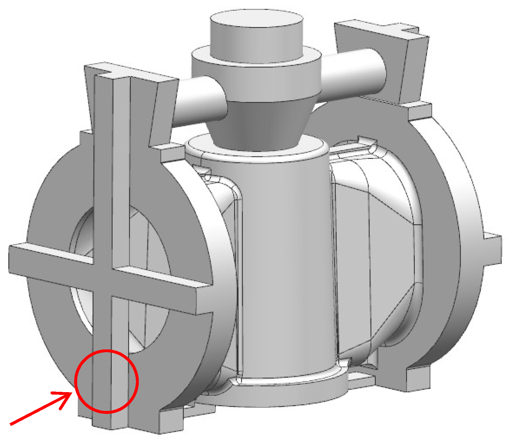
3. Process Design and Simulation Optimization

3.1. Process Design

The overall dimensions of the valve body selected for this study are 580 × 605 × 750 mm, with the thinnest wall thickness of 22 mm and a maximum wall thickness of 70 mm at the flange. The specific structure and wall thickness analysis are shown in Figure 2. The process of formulating the technology for this valve body design mainly considers the following aspects:
(1)
Casting method;
(2)
Difficulty in shell preparation;
(3)
Casting shrinkage compensation effect;
(4)
Craft output yield.
The valve body is made of a Zr705C alloy, which has a melting point as high as 1852 °C and solidifies in a paste-like manner [17]. The internal casting is prone to forming dendritic shrinkage, and the process design must also consider rapid filling. The author, based on previous process design foundations and following process design principles, used ProCAST 2018.0 software to analyze the rationality of the process design more intuitively. At the same time, considering the structure and quality requirements of the casting, to avoid core suspension issues, the design adopts the idea of inverting the “plug valve” approach. The casting quality requirements here mainly refer to the requirements specified in the ASTM B752 standard regarding surface quality, internal defects, and so on. Given that the zirconium alloy casting is a high-pressure component, hot isostatic pressing technology will subsequently be used to densify the casting, so the design process focuses more on the thick flange area. Based on the above analysis, the author designed the casting process for the zirconium alloy casting, as shown in Figure 3. The pouring system includes a pouring cup, runner, and riser. The sprue is distributed in the thick and large parts of the valve body, including the flange. The pouring cup and riser are used to feed the solidification shrinkage of the valve body and flange, respectively.

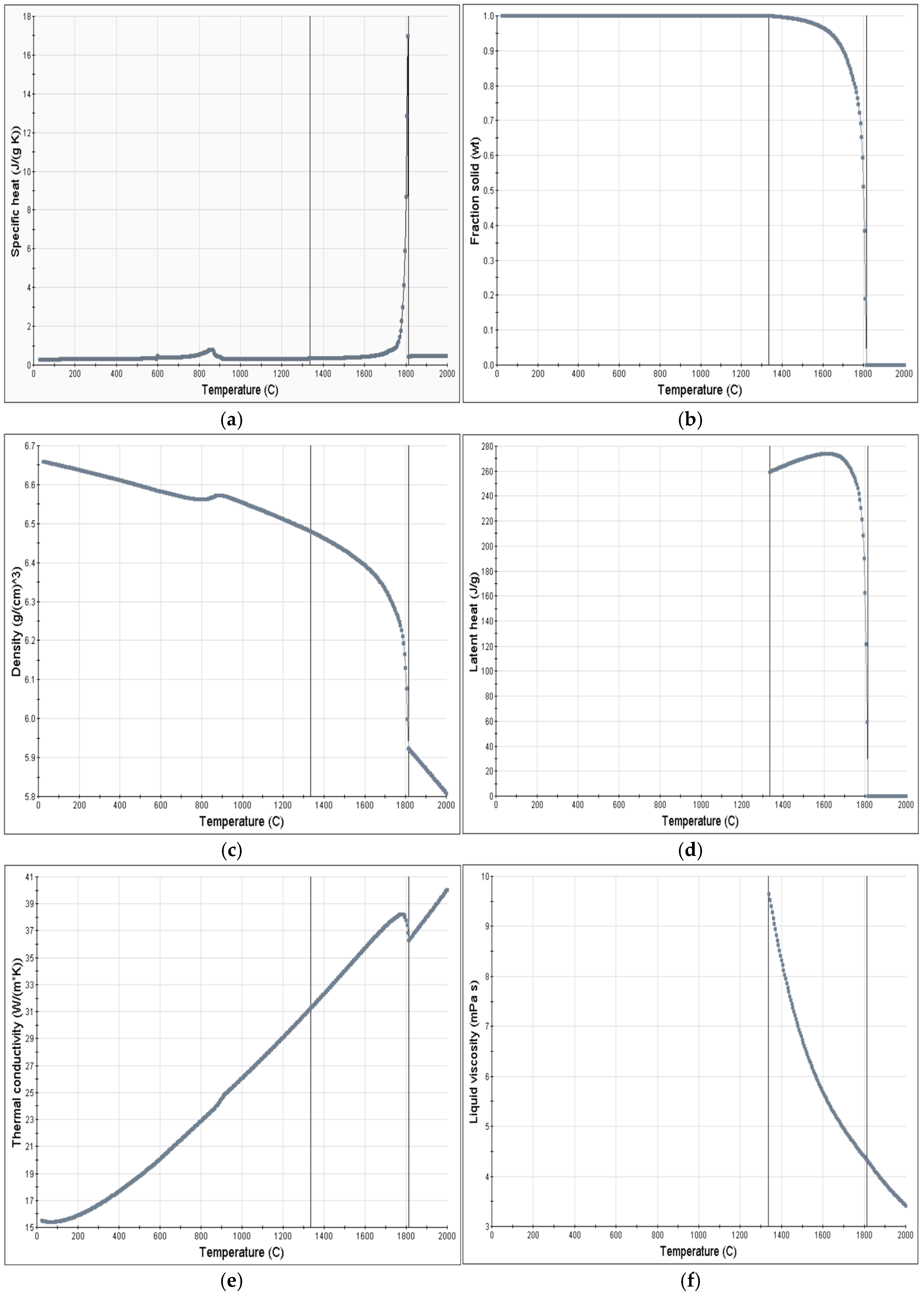
3.2. Preparation Before Simulation

The material of the valve body sample is a Zr705C alloy. The digital model is first divided into face mesh and hexahedral volume mesh using the Visual Mesh module. The mesh cell size is 8 mm, and the total number of elements in the volume mesh is 490,797 (Figure 4). Figure 5 shows the thermophysical property parameters of the alloy, including specific heat, fraction solid, density, latent heat, thermal conductivity, and liquid viscosity. All data and parameters in Figure 5 are automatically generated by Procast software after the selection of the casting material is completed. According to the actual casting process, the initial condition parameters include the following: a pouring temperature of 1920 °C, a pouring speed of 93 kg/s, and a filling time of 4.9 s. The interface heat transfer coefficient was simplified as a constant of 1000 W/m2·K.

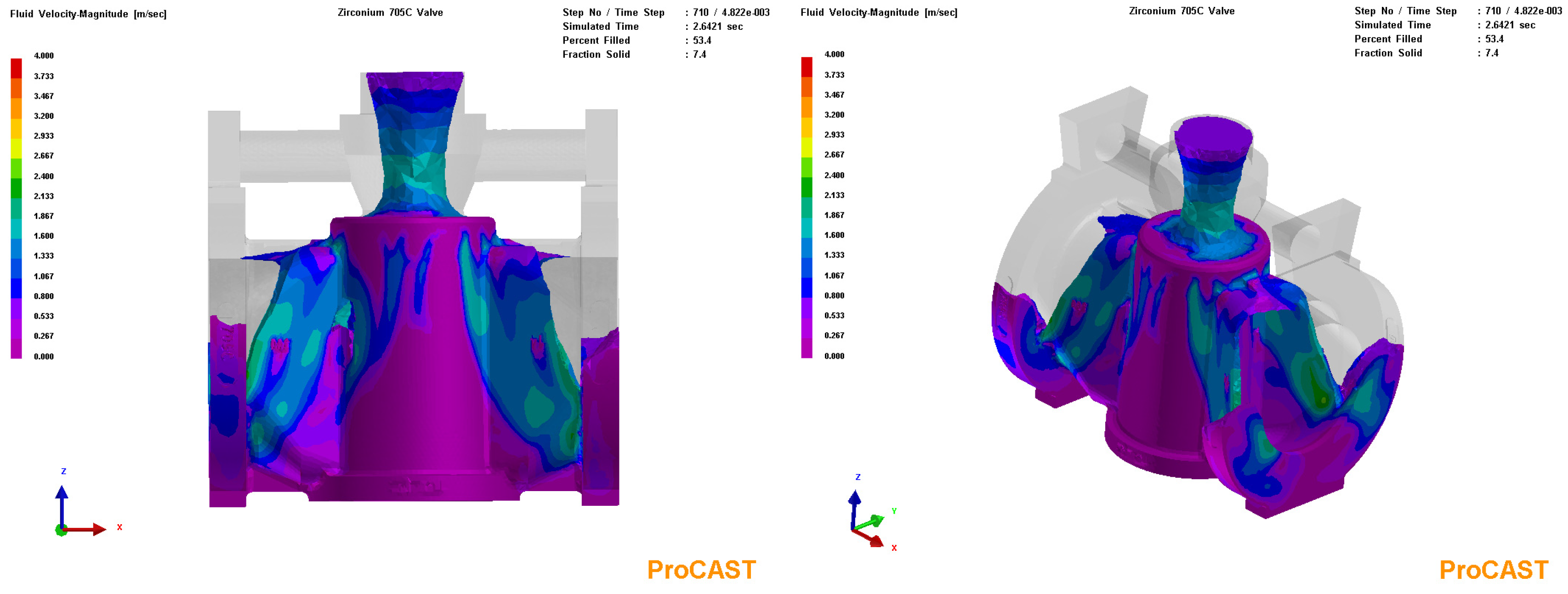
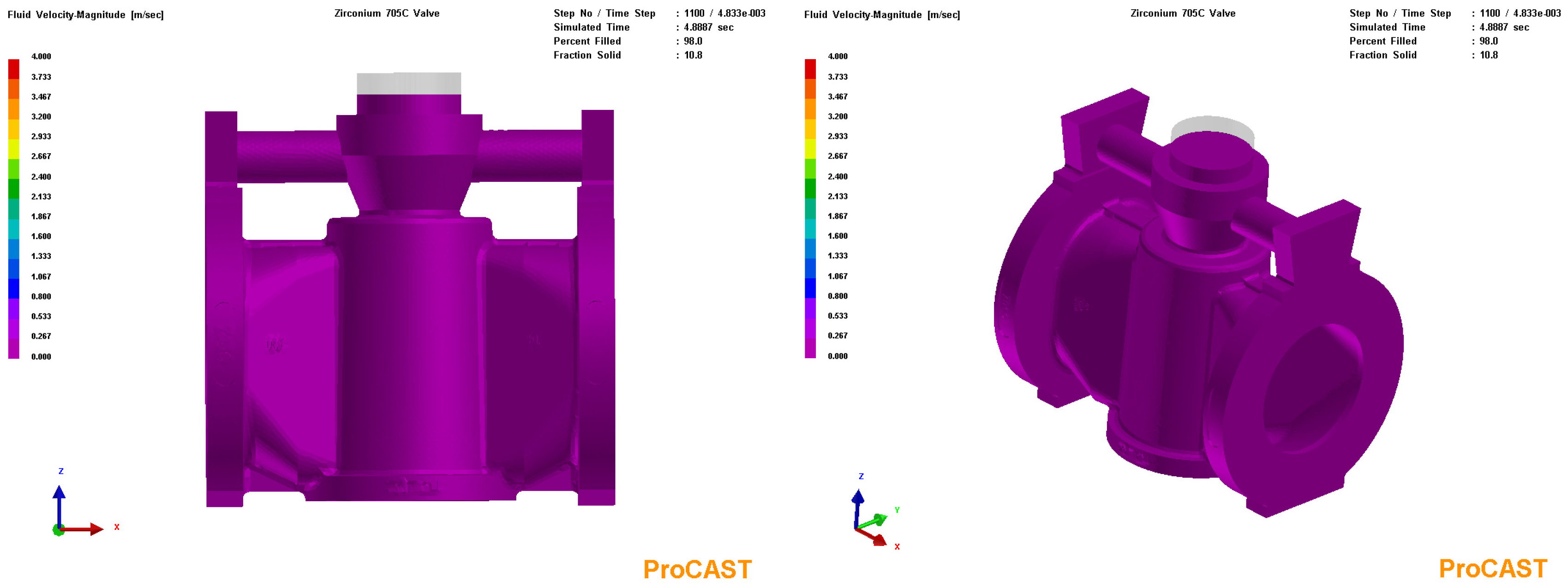
3.3. Process Simulation Analysis

According to the main design scheme, ProCAST casting simulation software is used for process analysis, and the casting adopts a single-type static pouring method. The specific analysis results are as follows.
Figure 6, Figure 7, Figure 8 and Figure 9 show the velocity field of the casting filling process, and Figure 10 shows the shrinkage porosity rate of the casting. It can be seen that the filling process of the casting is stable. The molten metal did not exhibit significant turbulence, and the filling occurred along the main casting from bottom to top, with no isolated liquid phase areas in the flange and valve body. As filling and solidification progressed, larger shrinkage porosity was generated (as shown in Figure 10). According to the simulation analysis results and combined with previous casting process experience, defects such as shrinkage porosity could not be completely eliminated after HIP treatment. Therefore, the casting process of the small-sized valve body could not fully meet the requirements for compensating for shrinkage and needs to be optimized.

3.4. Process Optimization

Through the simulation analysis of the casting process, it can be seen that the initial casting process can effectively fill the mold, but it cannot meet the shrinkage requirements of the casting and cannot ensure overall quality well. Therefore, it is necessary to optimize the casting process. Based on the distribution of defects, the process optimization mainly focuses on optimizing the shrinkage quality of the interface flange. First, new sprues are added at the butt flange and the plug flange, and secondly, the allowance of the plug side flange is increased, optimizing two casting processes. For details, see Figure 11 (left side is YH-1; right side is YH-2). The casting process remains consistent, and the specific simulation process and results are shown in Figure 12, Figure 13, Figure 14, Figure 15 and Figure 16 (left side is YH-1; right side is YH-2).
Figure 12, Figure 13, Figure 14 and Figure 15 show the velocity field of the casting filling. The left figure represents YH-1, and the right figure represents YH-2. Figure 16 shows the shrinkage porosity rate of the casting. The simulation results indicate that both optimized processes can fill the mold smoothly, but the final result of the YH-1 process shows that the shrinkage defect is still relatively large. In contrast, the YH-2 process has smaller and fewer defects, and the quality at the flange significantly improved after optimization. The YH-2 process meets the design requirements mainly because the valve body structure is generally simple and the filling time is relatively short. The zirconium alloy has a low degree of alloying, similar to pure metal, and solidifies very quickly in thin-walled areas with fewer defects, while the thick areas do not meet the gradient solidification conditions. Therefore, simultaneous solidification is likely to occur, leading to a higher probability of shrinkage cavities and porosity. It appears that the process should focus on compensating for the thick areas. After considering the compensation for the butt flange and the plug valve flange, the YH-2 process has significantly fewer defects, thus meeting the process requirements.

4. Experiment

Experiments were conducted using the YH-2 process optimized through simulation, with the material being Zr705C (composition requirements are shown in Table 1). The casting equipment used was a vacuum self-consumption electrode arc shell melting furnace. The gravity casting process was adopted during pouring and filling, and the castings underwent hot isostatic pressing treatment. Sampling and analysis were carried out on the outer surface of the flange part of the cleaned valve body casting, as shown in Figure 17, and the quality analysis of the welding process during the subsequent casting trimming was carried out, mainly including the analysis of structure and mechanical properties. A microstructure analysis of the sample was conducted using a metallographic microscope (ZEISS Axio Vert.A1, CARL ZEISS, Oberkochen, Germany). The orientation relationship between the phases was determined with an electron backscatter diffractometer (EBSD, NordlysMax2, Oxford, UK). The elemental distribution on the sample surface was analyzed by using an energy-dispersive spectrometer (EDS, X-MaxN50, Oxford, UK). The hardness gradient from the surface to the core of the sample was analyzed by using a Vickers hardness tester (Wilson VH1150, Buehler, Chicago, Germany). Table 1 shows the chemical composition of Zr705C castings.

5. Results and Analysis

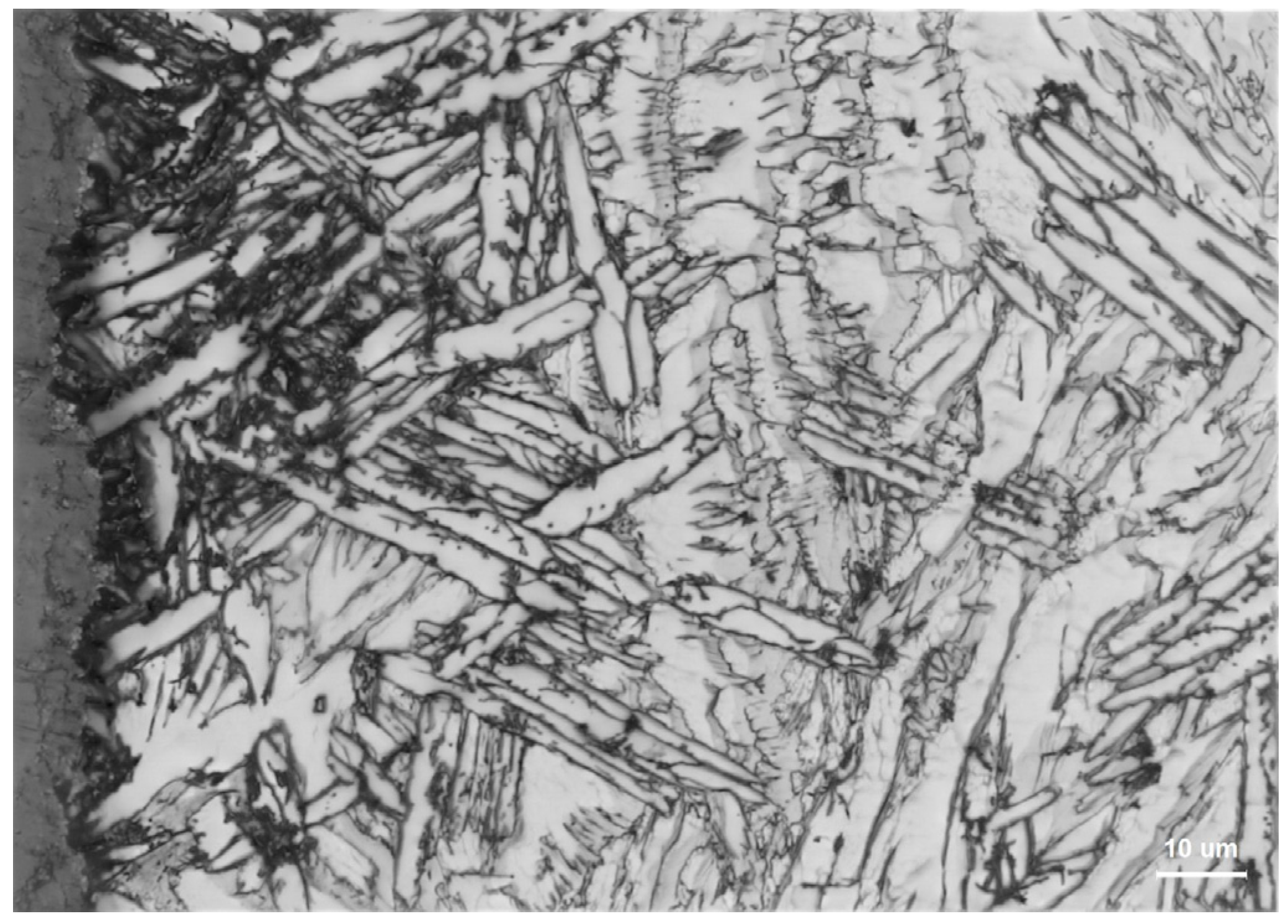
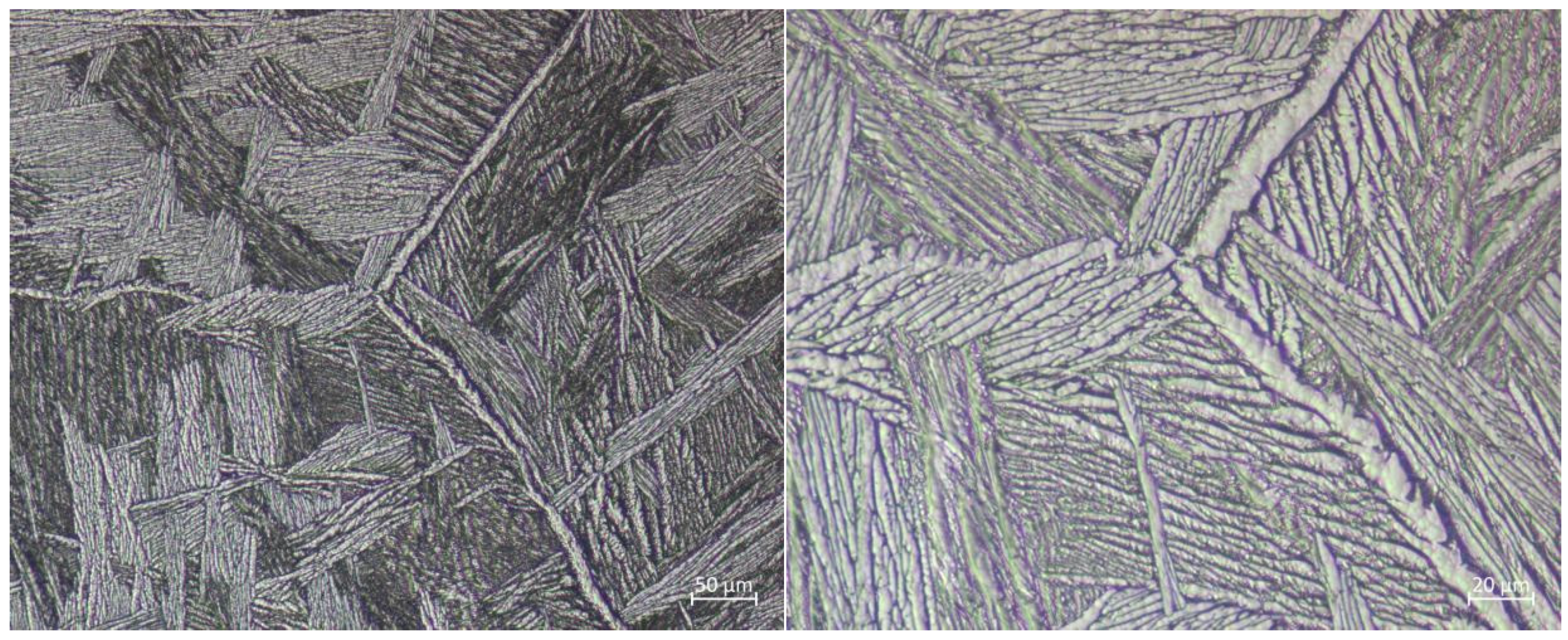
5.1. Metallographic Analysis
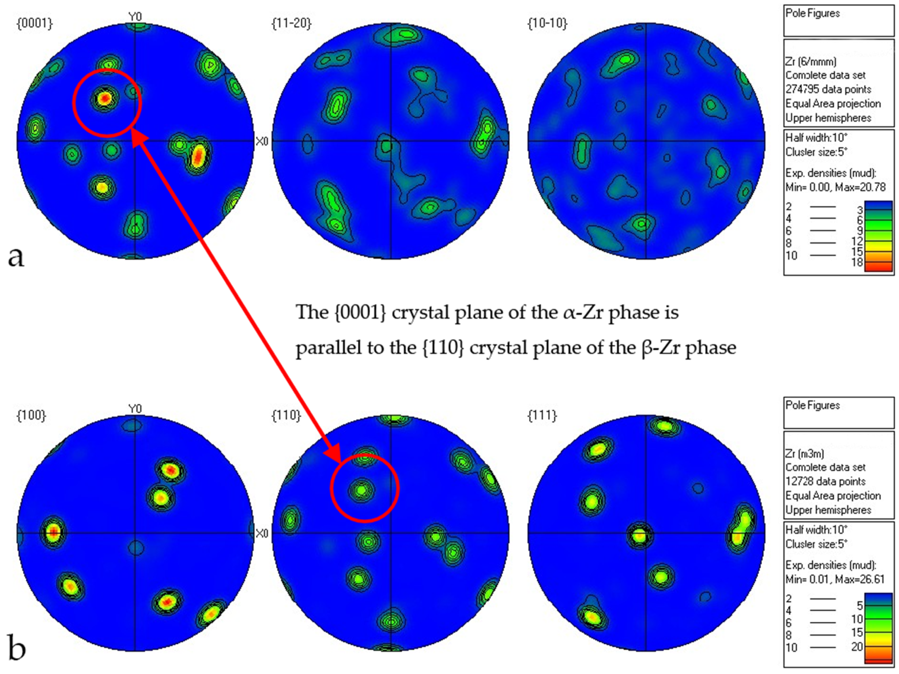
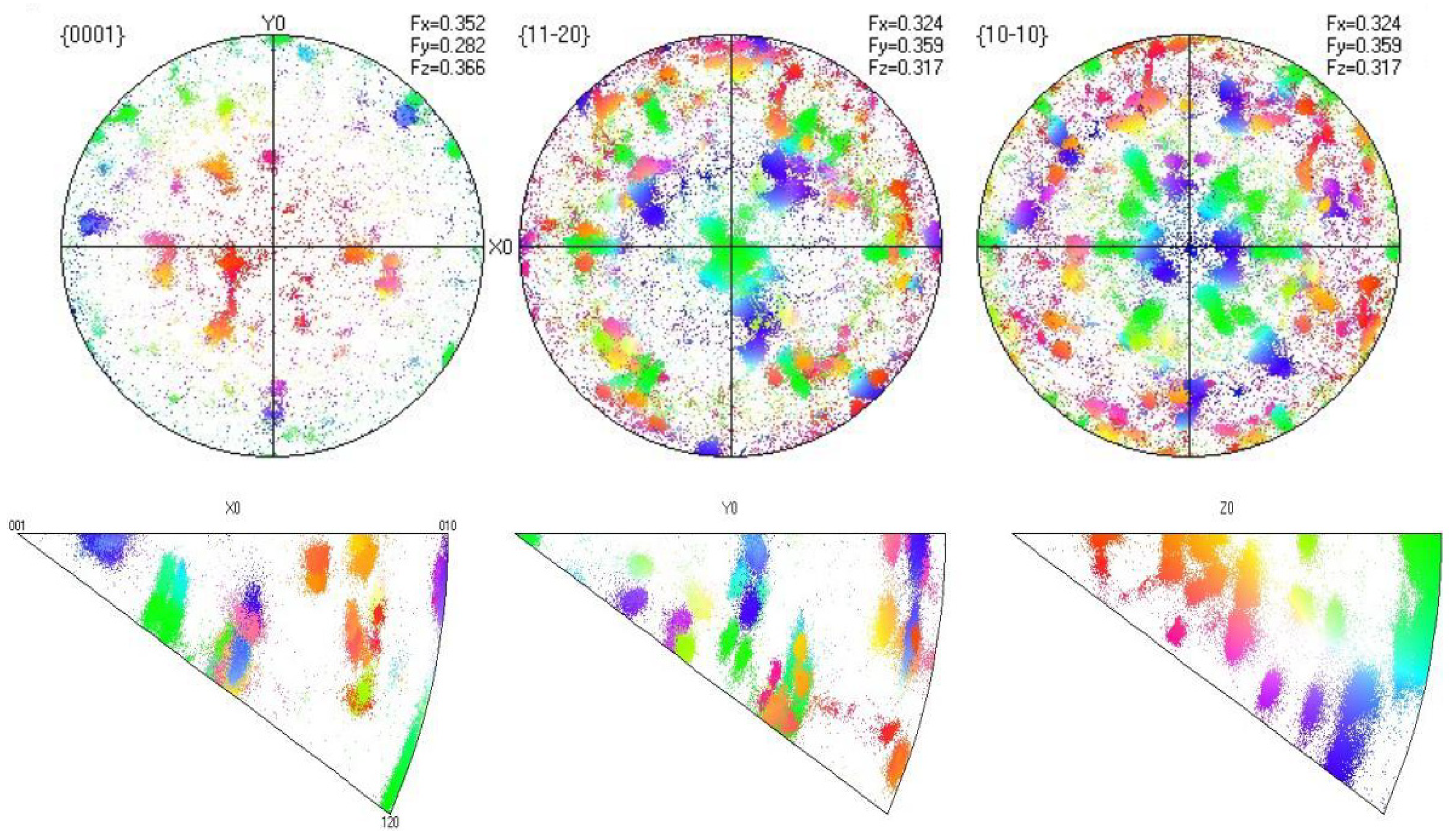
Scheme 100. times is shown in Figure 18, where the structural changes from the outer surface to the interior are distinctly divided into three layers: surface contamination region → contamination diffusion region → matrix lamellar grain region. The further magnified microstructural appearance is shown in Figure 19, Figure 20 and Figure 21. The surface structure, when magnified, reveals smaller and irregularly arranged grains. Under the action of high temperature, the alloy melt and the shell materials will undergo a violent interface reaction. The O element diffuses into the zirconium melt, causing the formation of metamorphosis structure on its surface. It is characterized by higher brightness under the microscope, accompanied by higher hardness and higher brittleness. The depth of the contaminated layer is about 20–30 μm. In addition to this, the O element will continue to diffuse into the interior of the alloy matrix. The zone of effect is about 100 μm or deeper. However, the structure, hardness, and brittleness of this region are not greatly affected. The innermost layer of the casting is the equiaxed grain region, composed of uniformly arranged dendritic lamellar structures, with relatively coarse grain sizes.

5.2. EBSD Analysis

Using EBSD technology is one of the important research methods for the crystal orientation and phase distribution of zirconium alloys. The following are the EBSD detection results of the Zr705C alloy base material. Figure 22 presents the phase distribution map of the Zr705C alloy base material, which shows a typical fully lamellar structure, with most areas being lamellar α phase, and a small amount of granular β phase is also present. Figure 23 and Figure 24 display the inverse pole figure and Euler angle figure of the Zr705C alloy base material, respectively, reflecting that there is no phenomenon of microstructural inhomogeneity in the alloy, and the grain orientation distribution is relatively random, overall exhibiting isotropy. Figure 25 shows the pole figures of the α-Zr phase and β-Zr phase, with the test results indicating that the {0001} crystal plane of the α-Zr phase is parallel to the {110} crystal plane of the β-Zr phase, which indicates a certain crystallographic orientation relationship between the two phases. Figure 26 shows the Cohen coefficients of the {0001} plane in three directions as 0.352, 0.282, and 0.366, indicating that there is no significant strong texture in the cast Zr705C alloy base material. In the present investigation, the EBSD technique was employed to systematically characterize the initial crystallographic condition and as-cast microstructure of zirconium alloy specimens. Furthermore, this analytical methodology was applied to elucidate the twinning behavior and predominant deformation mechanisms operative during the subsequent thermomechanical processing of the material. Chen et al. (2024) [27] and Li et al. (2025) [28] used EBSD to study the twin behavior during zirconium alloy processing and deformation and determined the relationship between twin growth and grain orientation, which is closely consistent with the research content of this paper.

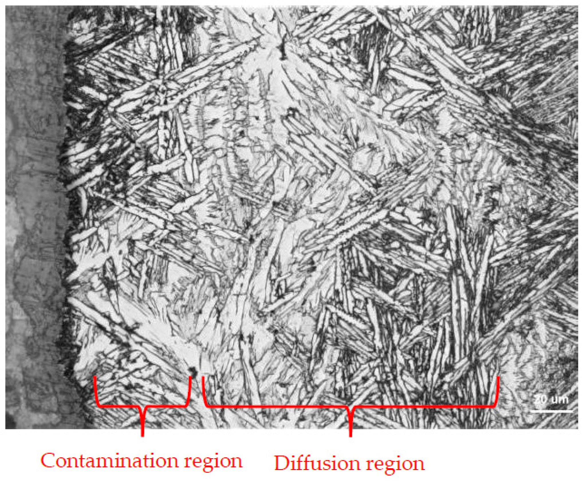
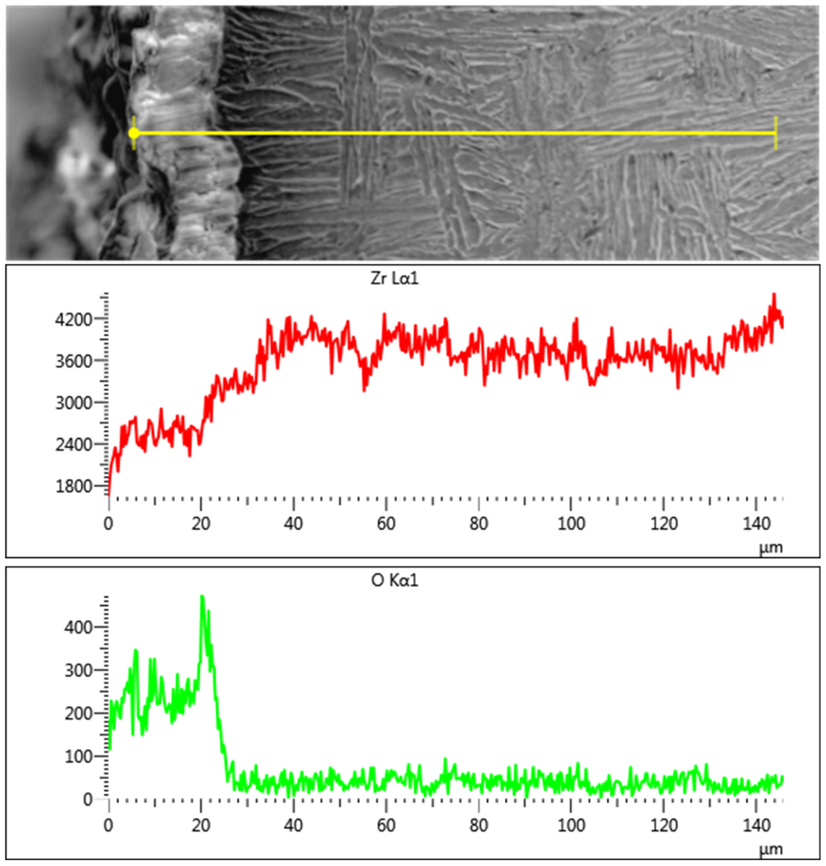
5.3. Analysis of Surface Diffusion Contamination Layer of Castings

Samples were taken from the outermost side of the valve body casting in direct contact with the cavity wall. After grinding and polishing, metallographic analysis, EDS elemental analysis, and hardness gradient testing were conducted in sequence. Figure 27 shows a metallographic structure photo of the surface sample of the valve body casting, where a uniform contamination layer can be clearly observed outside the surface quenching zone, with an average thickness of about 20–30 μm. However, the boundary line between the contamination layer and the casting matrix is not obvious but rather diffuses to a certain extent into the matrix, so the actual thickness of the contamination layer is several micrometers or even tens of micrometers thicker than what is observed under the microscope, which requires more precise detection methods to determine. Figure 28 shows an EDS line scan image of the valve body casting sample. The results indicate that there is a large amount of O in the contamination layer on the surface of the casting. Since the entire melting and pouring process occurs under vacuum conditions, this O can only originate from the casting shell. Therefore, it can be confirmed that the zirconium melt reacted with the shell during the pouring process, resulting in a contamination layer with a thickness of about 20–30 μm, which is consistent with the observations made using a metallographic microscope. Hardness gradient analysis was conducted on the casting sample, with the sample cross-section as the detection object. Starting from a distance of 20 μm from the surface, the hardness was measured at an interval of 10 μm each time, as shown in Figure 29. The hardness of the casting surface remains at a relatively high value before 30 μm, which is consistent with the previously obtained contamination layer thickness. After 50 μm, the hardness of the casting tends to stabilize, while at 40 μm, the hardness remains at a high level, but there is a significant difference compared to the hardness of the contamination layer. The reason for this phenomenon may be the presence of a rapid cooling layer, which causes the surface hardness of the casting to be greater than the matrix hardness. There may also be experimental errors, but overall, the contamination layer thickness obtained from the three detection methods is basically consistent.

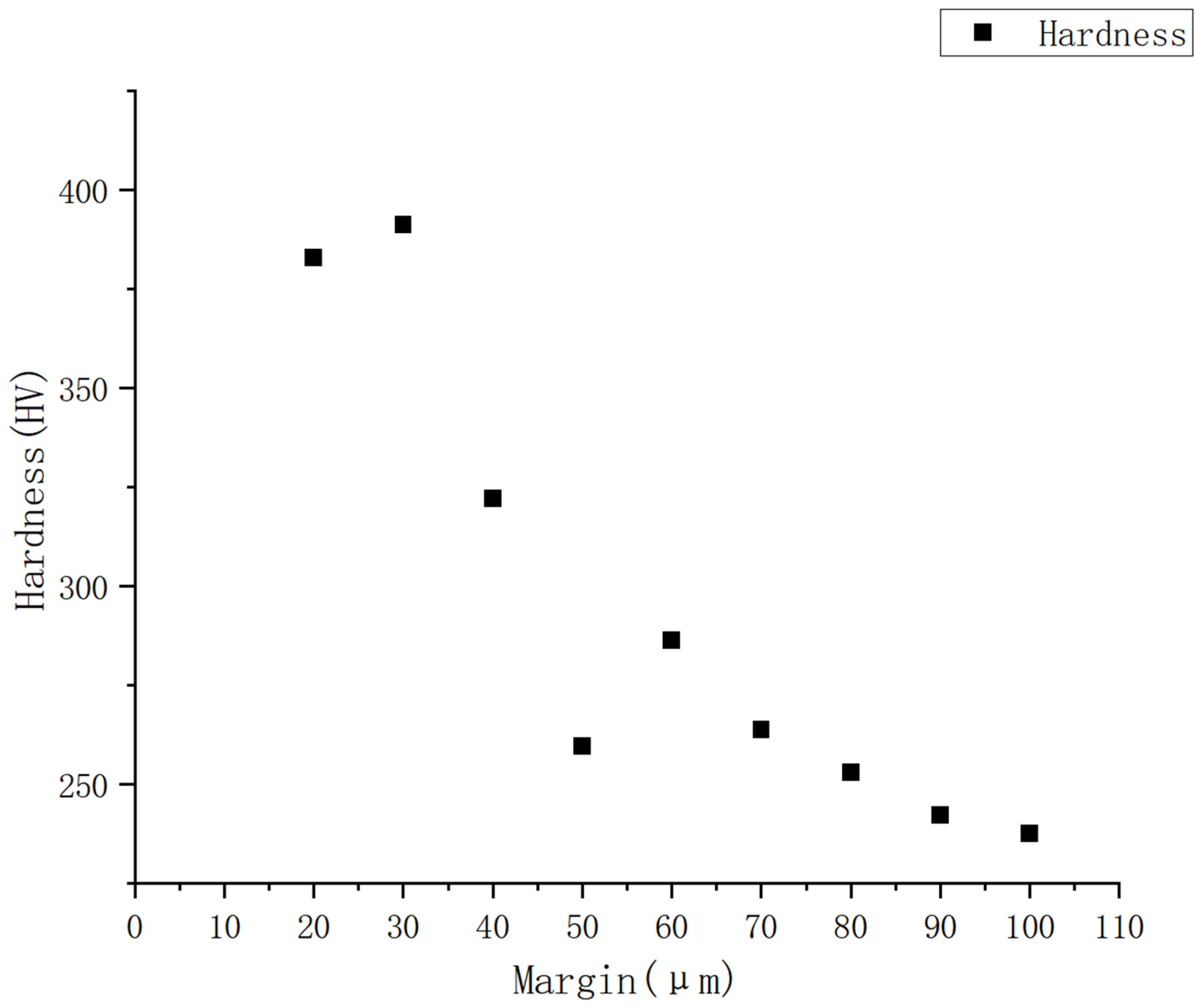
5.4. Mechanical Property Testing

Currently, the standard for zirconium alloy castings in China is Zirconium and Zirconium Alloy Castings (Standard No.: YS/T 853-2012), and the international standard is ASTM B752. Performance requirements are shown in Table 2.
Through the sampling and analysis of the riser part of the casting system, as shown in Figure 30, the results meet the requirements of the relevant standards.

6. Key Points of Welding Quality Control

Welding is an important step in the production process of zirconium alloy valve body castings. Based on extensive production experience, zirconium alloy valve bodies are prone to surface cracking after welding [29,30]. Combined with sampling observations and preliminary experimental research, cracks mainly concentrate near the residual contamination layer on the valve body surface. As shown in Figure 31, the valve body casting needs to undergo a series of surface treatments before welding, and most of the contamination layers were removed, but a small portion of the contamination layer remains, significantly increasing the probability of cracks occurring in these areas.
Through the above experiments, it can be concluded that in order to obtain a qualified welding quality of zirconium alloy valve bodies, in addition to controlling the temperature, acidity, and quality of the welding joint during welding, the preparation, processing, surface treatment, and cleaning steps before welding are also very important. The following points should be specifically noted [31,32]:
(1)
The actual castings should be slightly thicker than the required castings to allow for later surface finishing and defect removal.
(2)
The cutting and gouging of zirconium alloy castings are carried out using oxygen, plasma, or water jet or laser equipment, and it is not recommended to use carbon electrodes for arc cutting, which can easily cause more pollution.
(3)
During the thermal cutting process, an oxidation and contamination layer will form near the cutting surface, which should be removed before welding, with a thickness of at least 0.8 mm, 1.6 mm after oxygen, 1.6 mm after plasma, and 0.8 mm after laser.
(4)
Sandblasting, shot blasting, and steam sandblasting are used to remove high-temperature oxide layers and lubricants from surfaces. Mechanical descaling media can include alumina, silicon carbide, silica sand, zircon sand, and steel shot, and methods such as ultrasonic cleaning, steam degreasing, or the use of electrolytic alkaline cleaning systems are used to remove grease and lubricants.
(5)
Pickling, as the final cleaning step for castings, requires attention: maintaining a ratio of nitric acid to hydrofluoric acid of 10:1 can minimize the casting’s absorption of hydrogen. All oxides and scale should be removed to prevent the finished product from being preferentially etched. After pickling, the product should be immediately rinsed with cold water to avoid the contamination of the surface by residual fluorides or chlorides.
The welding repair process of castings, as an important means of salvaging castings, is closely related to the final use of the castings, so the control of the welding process for zirconium alloys is very important. Moreover, zirconium alloys are highly chemically reactive and can easily react with gases such as O, N, and H in the air, so strict control is needed in the production process considering the following aspects [33,34,35]:
(1)
Protective gas: High-purity argon gas (purity > 99.999%) should be used.
(2)
Welding wire material and cleanliness: The welding wire should be made of wire with lower levels of N, H, and O, and it must be ensured to be clean before use.
(3)
Base material cleaning: It must be ensured that the base material is clean and tidy.

7. Conclusions

(1)
Process Optimization: The numerical simulation-guided redesign of the casting system and riser configuration (YH-2 process) effectively addressed shrinkage porosity in thick-walled regions, achieving stable mold filling and meeting stringent quality requirements for high-pressure Zr705C valve bodies. This approach offers a replicable methodology for large-scale zirconium alloy casting production.
(2)
Microstructural Insights: The microstructure of Zr705C castings exhibits three distinct zones: a surface fine-grained layer, a transition columnar grain region, and an internal equiaxed grain structure. The metallurgical composition comprises a lamellar α-phase and granular β-phase, with crystallographic orientation relationships between phases confirmed via EBSD analysis.
(3)
Surface Contamination Control: A diffusion reaction layer (20–30 μm thick) formed due to melt–shell interactions during casting. This layer, rich in oxygen, necessitates rigorous surface machining and pre-welding treatments to eliminate contamination-induced defects.
(4)
Welding Quality Assurance: Comprehensive surface preparation, including mechanical descaling, pickling, and contamination layer removal, is critical to prevent welding cracks. Process parameters such as argon purity (>99.999%) and welding wire cleanliness were identified as key factors for defect-free welds.
(5)
Practical Implications: The integration of simulation, optimized casting parameters, and post-processing protocols provides a robust foundation for the domestic production of high-integrity zirconium alloy components, which can effectively reduce reliance on imported castings. Future work should explore advanced mold materials to further minimize contamination and enhance casting surface quality.

Author Contributions

Conceptualization, Y.Z. (Youwei Zhang) and Z.S.; methodology, Z.S.; software, Y.Z. (Youwei Zhang); validation, D.J., C.B. and X.L.; formal analysis, Y.Z. (Youwei Zhang) and Q.Y.; investigation, Y.Z. (Yong Zang); resources, Q.Y.; data curation, X.L. and Q.Y.; writing—original draft preparation, Y.Z. (Youwei Zhang); writing—review and editing, D.J.; visualization, C.B.; supervision, Q.Y.; project administration, C.B.; funding acquisition, Z.S. All authors have read and agreed to the published version of the manuscript.

Funding

The authors would like to acknowledge the support provided by International industrial technology research and development project (International, Hong Kong, Macao and Taiwan) (2024JH2/101900027) and Liaoning Provincial Science and Technology Plan Joint Plan project (2023020930-JH2/1017).

Data Availability Statement

The original contributions presented in this study are included in the article. Further inquiries can be directed to the corresponding authors.

Conflicts of Interest

Author Youwei Zhang was employed by China Academy of Machinery Science and Technology Group Co., Ltd and China Academy of Machinery Shenyang Research Institute of Foundry Co., Ltd. And author Dehua Jin, Chunling Bao and Qian Yao was employed by China Academy of Machinery Shenyang Research Institute of Foundry Co., Ltd. The remaining authors declare that the research was conducted in the absence of any commercial or financial relationships that could be construed as a potential conflict of interest.

References

  1. Li, X.J. Overview of zirconium and zirconium alloys. Titan. Ind. Prog. 2011, 28, 38. [Google Scholar]
  2. Zinkle, S.J.; Was, G.S. Materials Challenges in Nuclear Energy. Acta Mater. 2013, 61, 735–758. [Google Scholar]
  3. Odette, G.R.; Zinkle, S.J. Structural Alloys for Nuclear Energy Applications; Elsevier: Amsterdam, The Netherlands; Munich, Germany; Oxford, UK; Cambridge, MA, USA, 2019; ISBN 978-0-12-397046-6. [Google Scholar]
  4. Hu, J.; Li, G.; Zhang, T.G.; Wang, J.B. Research status of industrial grade zirconium and zirconium alloy properties. Met. World 2020, 3, 23–26. [Google Scholar]
  5. Zhang, X.Q. Major applications of zirconium in the chemical industry. Rare Met. Mater. Eng. 1983, 2, 84–85. [Google Scholar]
  6. Luo, X.W.; Luo, F.C. Properties, application, production technology and development prospect of zirconium and hafnium material. Jiangxi Metall. 2009, 29, 17–21. [Google Scholar]
  7. YS/T 853-2012; Zirconium and Zirconium Alloy Casting Parts. China Standards Press: Beijing, China, 2012.
  8. ASME 2633-2011; 2633 Cast ASTM B 752-06 Zirconium Alloy Grades 702C and 705C Section VIII, Division 1. American Society for Testing and Materials: West Conshohocken, PA, USA, 2011.
  9. Kautz, E.; Gwalani, B.; Yu, Z.; Geelhood, T.V.K.; Devaraj, A.; Senor, D. Investigating zirconium alloy corrosion with advanced experimental techniques: A review. J. Nucl. Mater. 2023, 585, 154586. [Google Scholar]
  10. Jia, Y.J.; Lin, X.H.; Zou, X.W.; Han, W.Z. History, current situation and development trend of zirconium alloy. Prog. Chin. Mater. 2022, 41, 354–370. [Google Scholar]
  11. Qin, W. Improvement and Application of Zirconium Alloys. Metals 2018, 8, 794. [Google Scholar] [CrossRef]
  12. Chen, J.H.; Xie, Y.Q.; Wang, Y.T.; Zhou, Z.Q.; Yuan, H.Z.; Wang, L.N. Application of the elastic modulus with zirconium. Sci. Technol. Innov. Appl. 2021, 11, 32–34. [Google Scholar]
  13. Zhou, Y. Application of zirconium and zirconium alloys in chemical equipment. Chem. Eng. Des. 2003, 13, 19–22. [Google Scholar]
  14. Chen, X.; Li, Z.K.; Zhou, J.; Tian, F. Overview of the effects of alloy elements on the corrosion resistance of zirconium alloys. Therm. Work. Process 2015, 44, 14–19. [Google Scholar]
  15. Ma, M.L.; Zhu, Z.B.; Wang, S.J.; Yang, X.D.; Liu, Y.Q. Research progress of domestic zirconium alloy and its casting process. Foundry Eng. 2020, 41, 986–989. [Google Scholar]
  16. Coleman, C.E. The Metallurgy of Zirconium; International Atomic Energy Agency. IAEA: Vienna, Austria, 2022; ISBN 978-92-0-109221-2. [Google Scholar]
  17. Wang, S.; Fan, H.Y.; Zhou, C.C.; Zhang, L.J.; Ying, S.H. Research on the melting technology of niobium-containing zirconium alloy. Therm. Process. Process 2008, 9, 15–18. [Google Scholar]
  18. Yao, Q.; Zhang, Y.W.; Bao, C.L.; You, T. Research on the casting process of zirconium alloy valve body casting. Foundry 2016, 65, 632–638. [Google Scholar]
  19. Li, B.T.; Chen, G.Y.; Kang, J.Y.; Ali, W.; Qin, Z.W.; Lu, X.G.; Li, C.H. Research status of refractory materials for precision casting and smelting of zirconium alloy. Titan. Ind. Prog. 2017, 34, 6–11. [Google Scholar]
  20. Klotz, U.E.; Legner, C.; Bulling, F.; Freitag, L.; Faßauer, C.; Schafföner, S.; Aneziris, C.G. Investment Casting of Titanium Alloys with Calcium Zirconate Moulds and Crucibles. Int. J. Adv. Manuf. Technol. 2019, 103, 343–353. [Google Scholar] [CrossRef]
  21. Tian, Y.W.; Zheng, S.Q.; Li, B.B.; Li, W.D.; Yang, X.D.; Liu, Y.Q. Study on the welding technology of 705C zirconium alloy thick plate GTAW. Therm. Process. Process 2023, 52, 99–101+117. [Google Scholar]
  22. Zhang, T.G.; Wang, J.B.; Li, G. Research status of welding method of industrial zirconium alloy. Chin. Foreign Entrep. 2020, 2, 154. [Google Scholar]
  23. Tong, L.; He, X.M.; Diao, L.F.; Sun, W.C.; Cui, S.P. Study on welding and forming of zirconium alloy square pipe. Weld. Tech. 2019, 48, 55–57. [Google Scholar]
  24. Zhou, Y. Recent research progress of welding technology of industrial grade zirconium and zirconium alloy. Chin. Foreign Entrep. 2019, 34, 87. [Google Scholar]
  25. Jiang, F. Study on the welding properties of the new zirconium alloy pipe and rod. Weld. Tech. 2019, 48, 40–43. [Google Scholar]
  26. Wu, J.C. Key points for welding quality control for zirconium pipes. Weld. Tech. 2020, 49, 100–104. [Google Scholar]
  27. Chen, X.; Chen, W.H.; Jolanta, Ś.; He, W.; Liu, Q. Quasi-in-situ EBSD quantification investigation of the {10-12} deformation twinning in a zirconium alloy. Mater. Charact. 2024, 217, 114443. [Google Scholar] [CrossRef]
  28. Li, J.H.; Liu, A.; Liu, X.; Ye, X.; Wang, J.; Zhang, Y.; Zhang, Z. An investigation of slip and twinning behavior of a zirconium alloy during plastic deformation based on in-situ SEM-EBSD. J. Alloys Compd. 2025, 1010, 177918. [Google Scholar] [CrossRef]
  29. Hai, M.N.; Wang, W.; Huang, F.; Xianjun, L.I.; Xiaogang, Y.U.N.; Yongqiang, Z.H.N.; Jixiong, L.I.; Fuchang, X.I.N.; Kuaishe, W.A.G. Research progress of industrial grade zirconium and zirconium alloy welding. Electr. Weld. Mach. 2018, 48, 87–91. [Google Scholar]
  30. Bi, Y.B.; Chen, B.B.; Sun, Z.Q.; Xu, Z.; Lu, L.; Zhang, X.; Luo, Z. Solid-state welding for dissimilar zirconium alloy under joule heating effect: Material flowing behavior, characteristics, evolution and formation of interface. J. Nucl. Mater. 2024, 600, 155296. [Google Scholar] [CrossRef]
  31. Wang, H.Z.; Fan, Q.R.; Li, Q.W.; Zhu, Q.M. Welding of zirconium tube. China Chem. Equip. 2011, 13, 44–48. [Google Scholar]
  32. Li, X.M. Welding of the zirconium pipes. Electr. Weld. Mach. 2006, 36, 57–59. [Google Scholar]
  33. Deng, J.; Luo, Y.; Yin, J.C. Study on welding technology and properties of zirconium alloy for spent fuel. Guangdong Chem. Ind. 2023, 50, 28–31. [Google Scholar]
  34. Zhao, Z.M.; Zhang, L.X. On the welding of the zirconium materials. Weld. Tech. 2003, 32, 20–21. [Google Scholar]
  35. Mikhail, S. Dissimilar welding and brazing of zirconium and its alloys: Methods, parameters, metallurgy and properties of joints. J. Manuf. Process. 2022, 75, 928–1002. [Google Scholar]
Figure 1. A flowchart of the casting production process for zirconium alloy castings.
Metals 15 00417 g001
Figure 2. Three-dimensional schematic diagram of zirconium alloy valve body and wall thickness analysis.
Metals 15 00417 g002
Figure 3. Schematic diagram of zirconium alloy valve body casting system.
Metals 15 00417 g003
Figure 4. Volume mesh of valve body.
Metals 15 00417 g004
Figure 5. Casting thermophysical parameters of Zr705C alloy. (a) Specific heat, (b) fraction solid, (c) density, (d) latent heat, (e) thermal conductivity, (f) liquid viscosity.
Metals 15 00417 g005
Figure 6. Velocity field at simulated time of 1.38 s (Before optimization).
Metals 15 00417 g006
Figure 7. Velocity field at simulated time of 2.64 s (Before optimization).
Metals 15 00417 g007
Figure 8. Velocity field at simulated time of 4.13 s (Before optimization).
Metals 15 00417 g008
Figure 9. Velocity field at simulated time of 4.88 s (Before optimization).
Metals 15 00417 g009
Figure 10. Solidification shrinkage porosity rate (Before optimization).
Metals 15 00417 g010
Figure 11. Two models after optimization.
Metals 15 00417 g011
Figure 12. Velocity field at simulated time of 1.38 s (After optimization).
Metals 15 00417 g012
Figure 13. Velocity field at simulated time of 2.64 s (After optimization).
Metals 15 00417 g013
Figure 14. Velocity field at simulated time of 4.13 s (After optimization).
Metals 15 00417 g014
Figure 15. Velocity field at simulated time of 4.88 s (After optimization).
Metals 15 00417 g015
Figure 16. Solidification shrinkage porosity rate (After optimization).
Metals 15 00417 g016
Figure 17. The position of the specimen sample relative to the casting.
Metals 15 00417 g017
Figure 18. Macrostructure organization: 100×.
Metals 15 00417 g018
Figure 19. Amplified surface contamination and diffusion layer: 500×.
Metals 15 00417 g019
Figure 20. Amplified surface contamination and diffusion layer: 1000×.
Metals 15 00417 g020
Figure 21. Matrix tissue structure: 200× and 500×.
Metals 15 00417 g021
Figure 22. EBSD image of Zr705C alloy base material (distribution of α and β phases).
Metals 15 00417 g022
Figure 23. Inverse pole figure of Zr705C alloy base material (IPF map).
Metals 15 00417 g023
Figure 24. Crystal Euler angle orientation map of Zr705C alloy base material.
Metals 15 00417 g024
Figure 25. Polar figure of α-Zr phase and β-Zr phase in Zr702C alloy base material: (a) α-Zr; (b) β-Zr.
Metals 15 00417 g025
Figure 26. α-Zr pole figure and inverse pole figure (The crystallographic orientation of the different grains is distinguished by color).
Metals 15 00417 g026
Figure 27. Microstructural characteristics of valve body casting surface: (a) magnified 100 times; (b) magnified 200 times.
Metals 15 00417 g027
Figure 28. EDS element detection results of valve body casting. Yellow line- it is the position selected by the EDS line scan.
Metals 15 00417 g028
Figure 29. Hardness gradient testing of valve body castings.
Metals 15 00417 g029
Figure 30. Casting system riser sampling site.
Metals 15 00417 g030
Figure 31. Location of casting cracks.
Metals 15 00417 g031
Table 1. Chemical composition of Zr705C.
MaterialZr + HfNbHfNCHFe + CrPO
Zr705C≥95.12.0~3.0≤4.5≤0.03≤0.1≤0.005≤0.3≤0.01≤0.3
95.4652.222.050.00130.0160.00370.160.0020.082
Table 2. Valve body mechanical property test results.
ProjectTensile Strength
Rm/MPa
Yield Strength Rp0.2/MPaElongation at Break
A/%
Brinell Hardness/HBW
Standard≥483≥345≥12≤235
Sample150939215169
Sample249938018.5171
Disclaimer/Publisher’s Note: The statements, opinions and data contained in all publications are solely those of the individual author(s) and contributor(s) and not of MDPI and/or the editor(s). MDPI and/or the editor(s) disclaim responsibility for any injury to people or property resulting from any ideas, methods, instructions or products referred to in the content.

