Article

Effect of Stress on High-Temperature Molten Salt Corrosion of T91 Steel

1
Technology Innovation Center of Boiler Clean, Low-Carbon, Efficient Combustion and Safety Evaluation, State Administration for Market Regulation, China Special Equipment Inspection & Research Institute, Beijing 100029, China
2
School of Energy Power and Mechanical Engineering, North China Electric Power University, Beijing 102206, China
*
Author to whom correspondence should be addressed.
Metals 2025, 15(4), 446; https://doi.org/10.3390/met15040446
Submission received: 28 February 2025 / Revised: 4 April 2025 / Accepted: 5 April 2025 / Published: 16 April 2025

Abstract

:
This paper reports the effects of different levels of tensile stress caused by quasi-static loading on the corrosion behavior of T91 steel in a molten salt environment. Corrosion tests were carried out in a molten salt environment with a NaCl:K2SO4:Na2SO4 ratio of 1:1:8 under different applied stresses. The corrosion behavior was investigated through measurements of the phase composition, oxide morphology, and elementary composition. The results indicated that a low tensile stress promotes the growth of chromium oxides near the substrate and enhances the corrosion resistance, but with an increase in stress, the chromium oxides that formed on the T91 steel are destroyed, accelerating the inward diffusion of sulfur into the substrate to increase corrosion. The mechanism underlying the effects of applied stress and temperature on the corrosion behavior of T91 steel is discussed.

1. Introduction

China’s energy structure is characterized by an abundance of coal, a scarcity of oil, and limited natural gas resources. This composition dictates that coal-fired power generation will remain the predominant method of electricity production for the foreseeable future. Consequently, China must continue to rely on coal-fired power as a long-term energy solution, particularly in light of global initiatives to enhance energy efficiency and reduce carbon emissions. However, given the increasingly stringent international regulations on carbon emissions, “high efficiency, energy conservation, and emission reduction” have emerged as the primary objectives for the development of modern power plant boiler technology. To align with global environmental protection and low-carbon standards, the technical upgrading of coal-fired power units has become imperative, especially the deployment of large-capacity, high-parameter units. The efficient operation of these advanced units not only enhances power generation efficiency and reduces coal consumption, but also significantly diminishes the emissions of carbon dioxide and other harmful pollutants. However, the elevation of boiler operating temperatures and pressures imposes stringent demands on the boiler materials. Power station boilers, characterized by high operation parameters (high temperature and pressure for the main steam), intricate structures, and demanding working conditions, are susceptible to many forms of damage to different components due to their diverse operational environments [1,2,3,4]. Notably, high-temperature corrosion on the flue gas side represents one of the most severe challenges, attracting significant attention from researchers around the world.
High-temperature corrosion on the flue gas side is primarily attributed to the interaction between sulfur-containing gases and the metal surface. At elevated temperatures, a protective oxide layer forms on the surfaces of the superheater and reheater tubes. However, this protective layer can be readily compromised by complex sulfates (for example, 3K2SO4+Fe2O3+3SO3→2K3Fe(SO4)3), thereby exposing the metal substrate to a corrosive environment. This corrosion mechanism not only results in tube wall thinning but may also lead to significant material losses. When corrosion escalates, the corrosion rate can reach up to 1 mm/year, posing a serious threat to the operational safety of the power station [5]. Currently, the majority of the research on high-temperature corrosion remains centered on laboratory conditions, typically employing non-stressed test specimens to simulate high-temperature corrosion environments. However, there are often substantial discrepancies between laboratory simulations and actual operating conditions, particularly concerning stress effects. In the real-world operating environment of a power station, the superheater and reheater tubes are subjected not only to high-temperature corrosion but also to stresses induced by high-pressure working media. This combination of stress and corrosion can significantly accelerate material degradation, especially at stress concentration sites where corrosion rates and damage severity can be exceptionally pronounced. Fu et al. [6] studied the corrosion behavior of HR3C in molten Na2SO4–K2SO4 salt under stress. The application of stress promoted a faster formation of protective Cr2O3, and thus decreased the corrosion rate. More protective oxides were also observed by other scholars using stress [7,8]. Khalid et al. [9] investigated the effect of the deformation substructure on the high-temperature oxidation of Inconel 625. A scattered oxide formed on the deformed specimens, which was attributed to the concurrent dynamic changes. Applying stress during high-temperature corrosion can result in the cracking and spalling of the oxide layer [10,11].
Given the inadequate strength and limited corrosion resistance of carbon steel, it is unsuitable as a material for superheaters and reheaters in supercritical boilers. A more suitable and efficient alternative is T91 steel. Due to the presence of high-temperature and high-pressure water within the boiler tube, the tube wall is subjected to significant stress. Through simulation analysis, it was determined that when the steam pressure in the superheater pipe is 26 MPa, the equivalent stress in the pipe wall is approximately 100 MPa. As the steam pressure decreases, the resultant equivalent stress acting on the pipe wall also diminishes accordingly. In this study, T91 steel, which is extensively utilized in superheater and reheater piping systems, was used to conduct high-temperature composite sulfate corrosion tests under varying tensile stresses of 25 MPa, 50 MPa, 75 MPa, and 100 MPa. Additionally, a control group without any applied stress was established for tensile testing under molten salt conditions at temperatures of 600 °C, 625 °C, and 650 °C. The tests were performed in a high-temperature creep testing machine with a molten salt chamber. The post-test analysis involved evaluating the morphology, corrosion layer thickness, and oxide composition using SEM, EDS, XRD, and other characterization techniques. The influence of temperature and stress on the high-temperature corrosion behavior was systematically analyzed, elucidating the role of tensile stress in such environments. This research provides a robust foundation for developing comprehensive safety and residual life assessment methods for power plant boilers.

2. Material and Methods

2.1. Experimental Material

The material selected for the experiment was a novel martensitic heat-resistant steel that was developed by the National Oak Ridge Laboratory. This steel has a lower carbon content compared to 9Cr1MoV steel, and the sulfur and phosphorus levels are strictly controlled; it also incorporates small amounts of vanadium and niobium for alloying purposes. T91-grade steel conforms to the American ASME SA-213 standard [12], with its domestic equivalent being 10Cr9Mo1VNbN. Its chemical composition is detailed in Table 1.

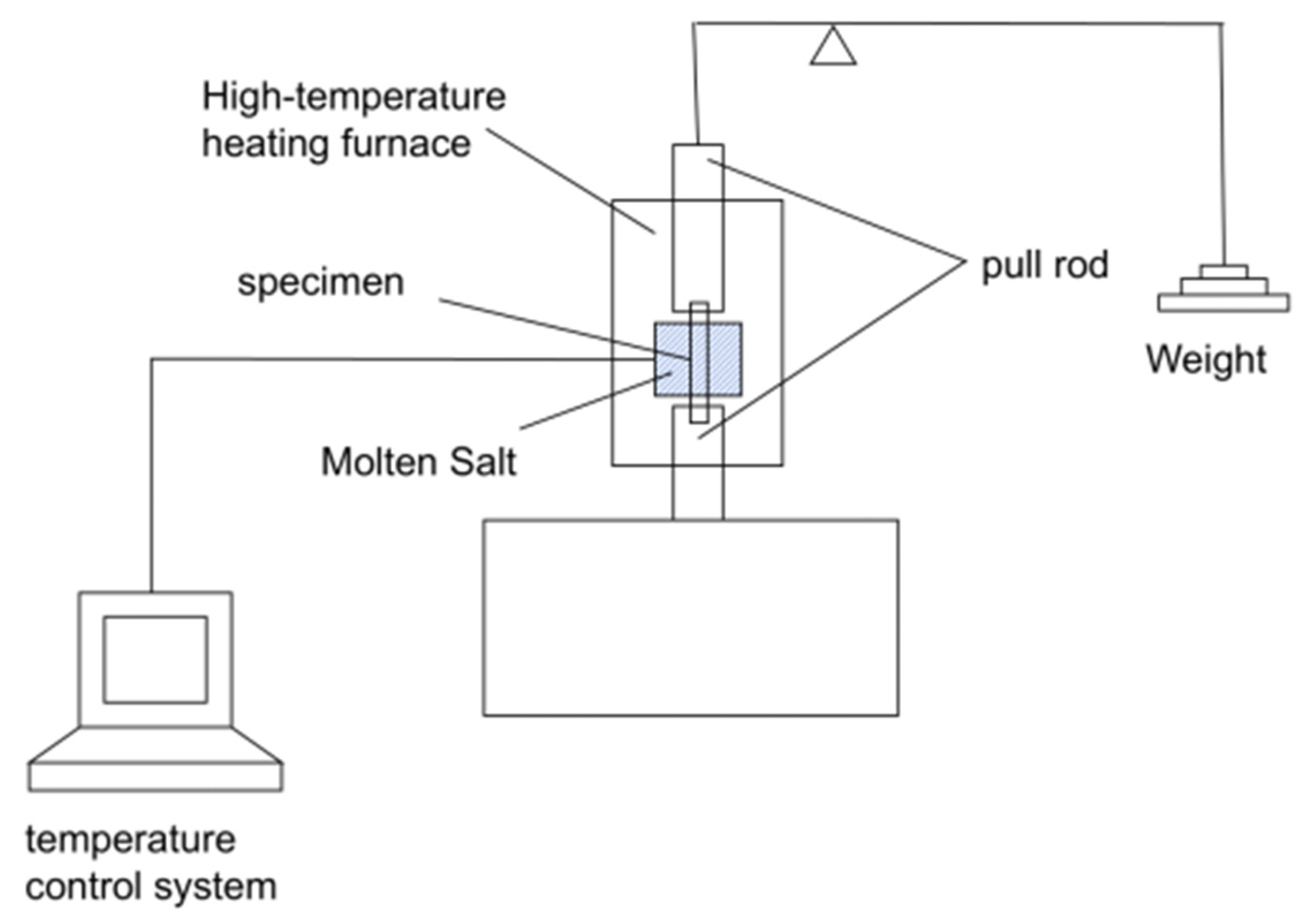
2.2. Experimental Method

A high-temperature creep testing machine was utilized in the experimental setup, and a custom fixture with internal threads compatible with the sample was designed. Figure 1 shows the high-temperature molten salt stress corrosion test system. A sleeve was developed to provide a molten salt environment and was connected to the rod specimen via the internal threads. The sleeve has a height of 51 mm (significantly larger than the standard gauge length) to ensure that the entire test was conducted within the molten salt environment. A rod specimen with a nominal diameter of 8 mm and a length of 122 mm was cut from the provided test tube; it featured a convex base for securing the sleeve, with a gauge length of 20 mm. All specimens were polished using 1.5 μm alumina powder and subsequently cleaned in an alcohol bath using an ultrasonic cleaner for 5 min.
The salts utilized in the experiment included analytically pure potassium chloride (KCl) with a purity of 99.5%, potassium sulfate (K2SO4) with a purity of 99%, and sodium sulfate (Na2SO4) with a purity of 99%. The mixed KCl:K2SO4:Na2SO4 salt was prepared at a mass ratio of 1:1:8, resulting in a eutectic temperature of 547 °C. During the experimental procedure, the three types of salts were weighed, ground, and thoroughly mixed.
Following the test, the sample was immersed in ultra-pure water to eliminate any residual salts and preserve the corrosion products. The surface characteristics of the sample were examined through scanning electron microscopy (SEM) using LEO 1530 field-emission at 10.00 kV coupled with energy dispersive X-ray spectroscopy (EDS), while the thickness of the corrosion layer was quantified via SEM analysis. Phase identification was conducted using X-ray diffraction (XRD) using copper radiation (λ= 1.542 A ˙ ), which also facilitated the determination of the composition of the corrosion products. For the cross-sectional analysis, the sample was first embedded in epoxy resin, subsequently ground using silicon carbide sandpaper with grit sizes of 200, 400, 600, 800, 1000, 1500, and 2000, and finally polished with a 1.5 μm diamond suspension. The microstructural features and elemental composition of the cross-section were then evaluated. Each experiment was conducted for a duration of 100 h.

3. Results and Discussion

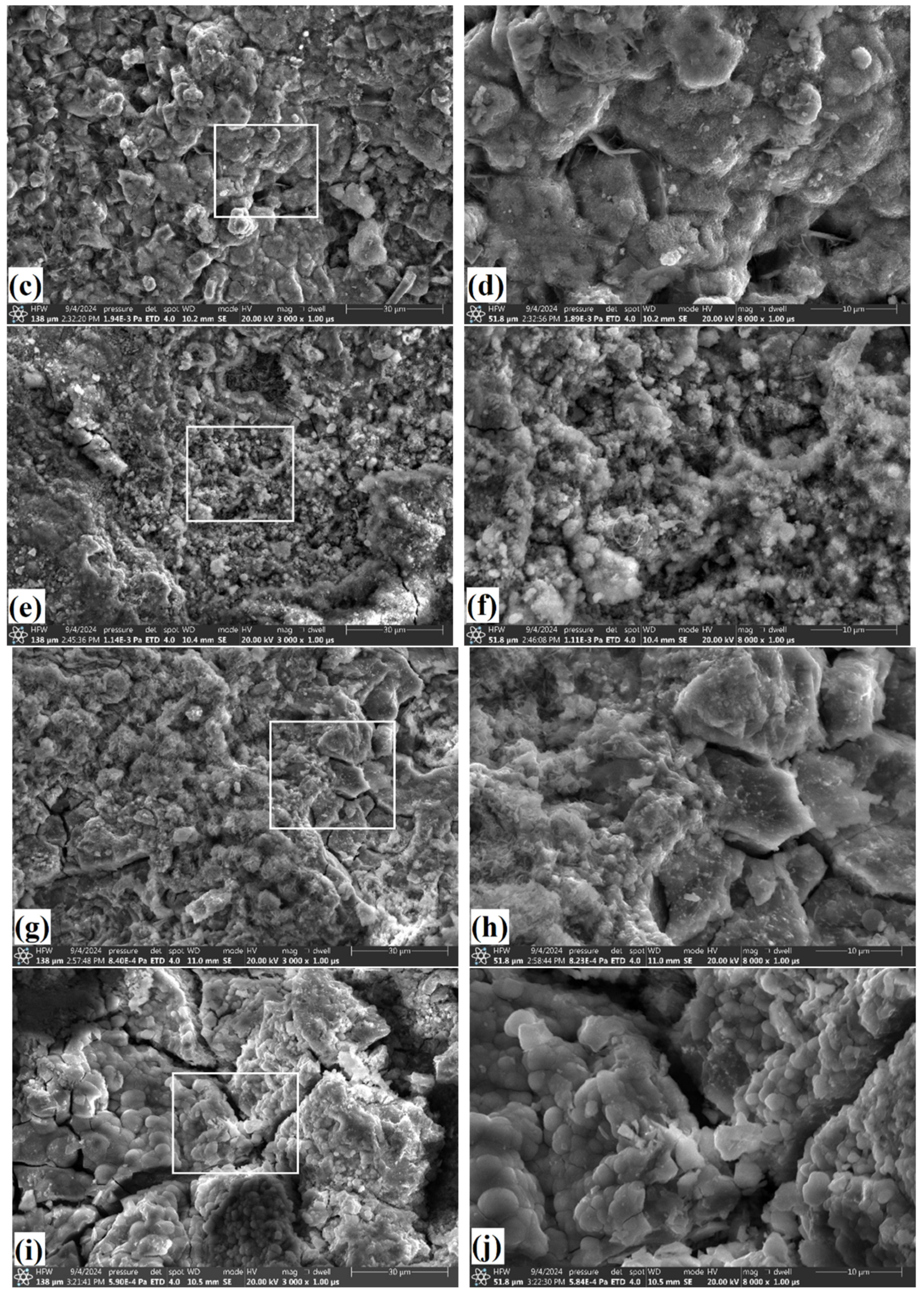
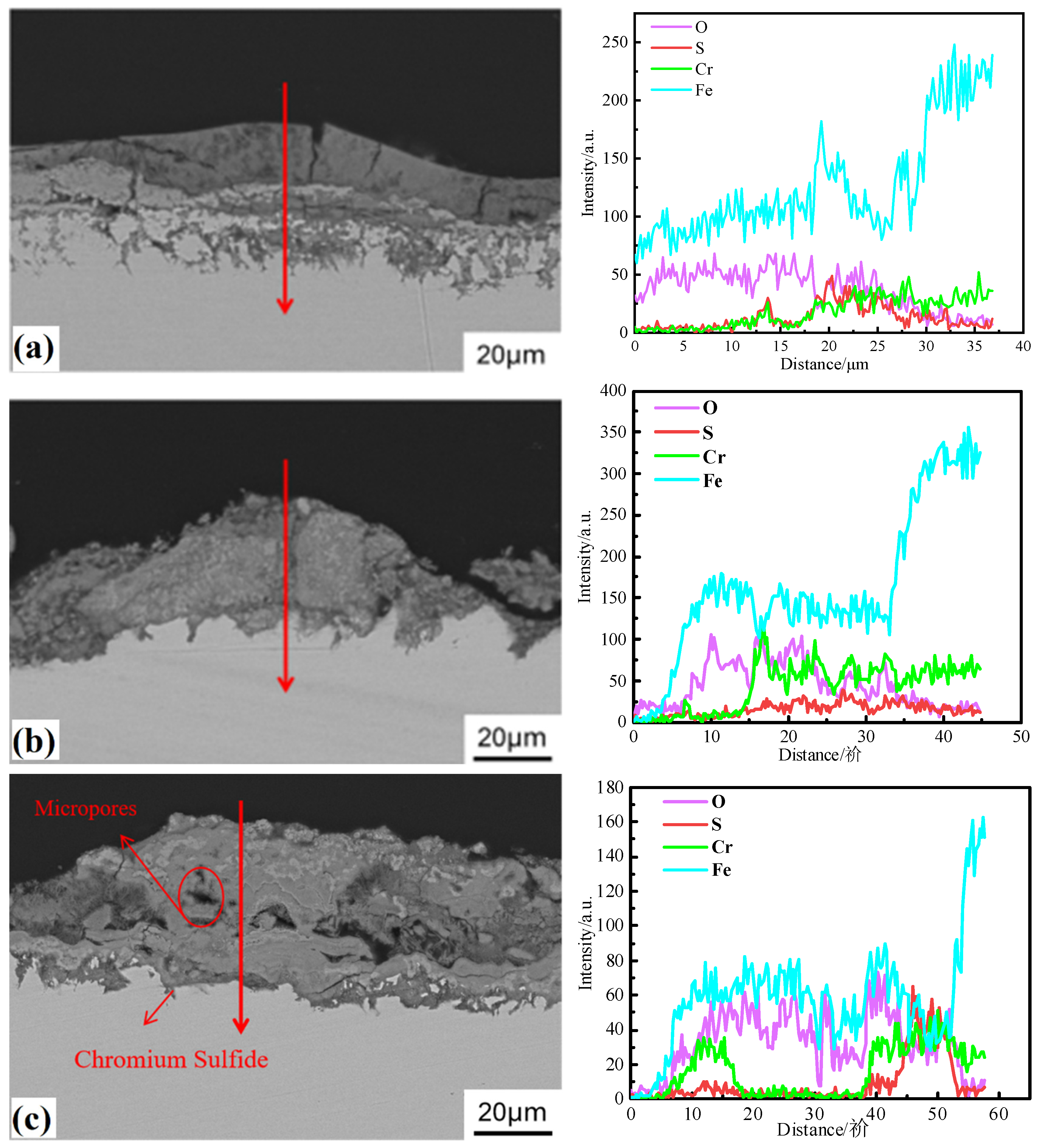
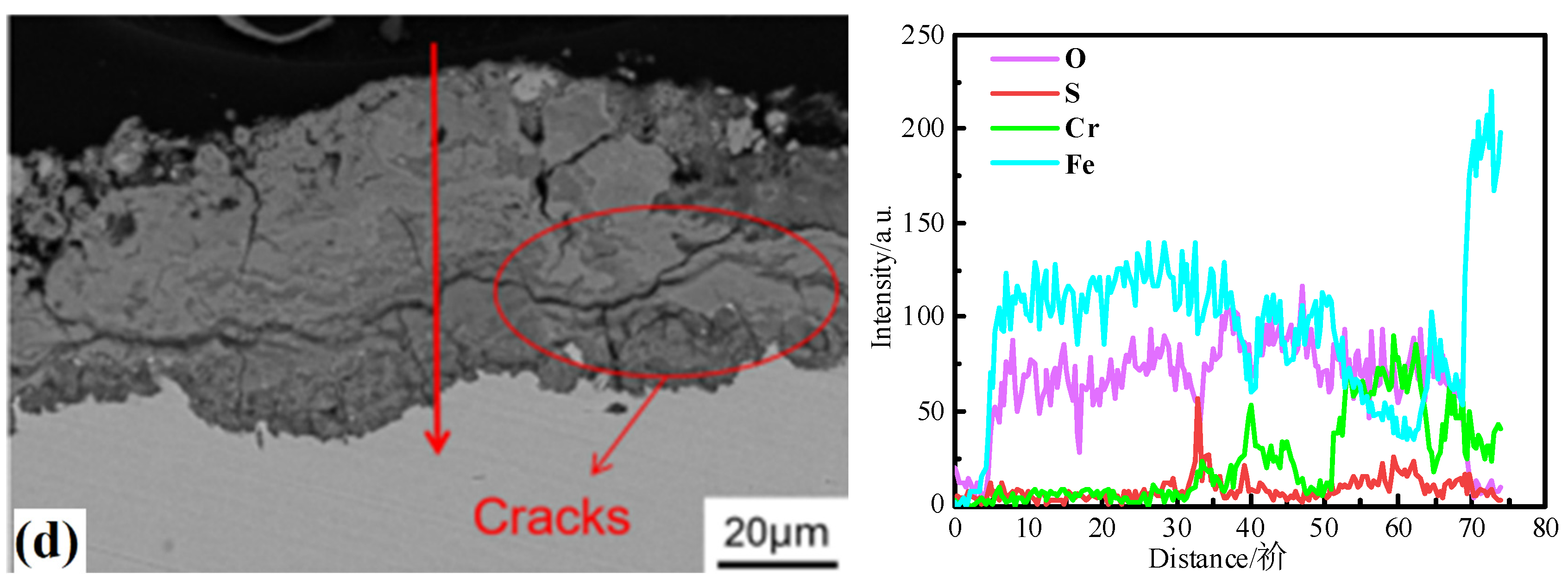
3.1. Surface Morphology

Figure 2 illustrates the topography and a high-magnification image of the corrosion surface under various stress conditions at 625 °C. In the absence of stress, the sample surface exhibited a knife-shaped porous structure. As the stress increased, this blade-like morphology disappeared, giving way to more mushroom-like corrosion features. At 50 MPa, fine granular corrosion products formed on the surface. When the stress reached 75 MPa, the crystalline corrosion surface developed multi-faceted granules. At 100 MPa, the corrosion products remained granular, but significant cracks appeared on the corrosion layer’s surface. It was evident that the stress significantly altered the surface morphology of the corrosion layer. With increasing stress, the particle size of the corrosion products initially decreased and then increased, peaking at 50 MPa. Beyond 75 MPa, surface cracks began to appear on the corrosion layer. Table 2 summarizes the composition and content of the major elements on the corrosion layer’s surface under the different stress levels at 625 °C. According to Table 2, the primary compositional elements of the surface corrosion layer were Fe, Cr, S, and O. The sulfur content in the corrosion layer initially increased and then decreased with increasing applied stress, reaching its maximum at approximately 50 MPa for 625 °C. Table 2 also shows the compositional elements at 600 °C and 650 °C for 0 and 25 MPa. The influence of temperature on element content is complicated. The sulfur and chromium content in the corrosion layer decreased with increasing applied stress at 600 and 650 °C. Figure 3 presents the surface morphology of the corrosion layer at temperatures of 600 °C and 650 °C. In Figure 3, it can be observed that these temperatures resulted in a change from a relatively regular structure to a coarser structure.

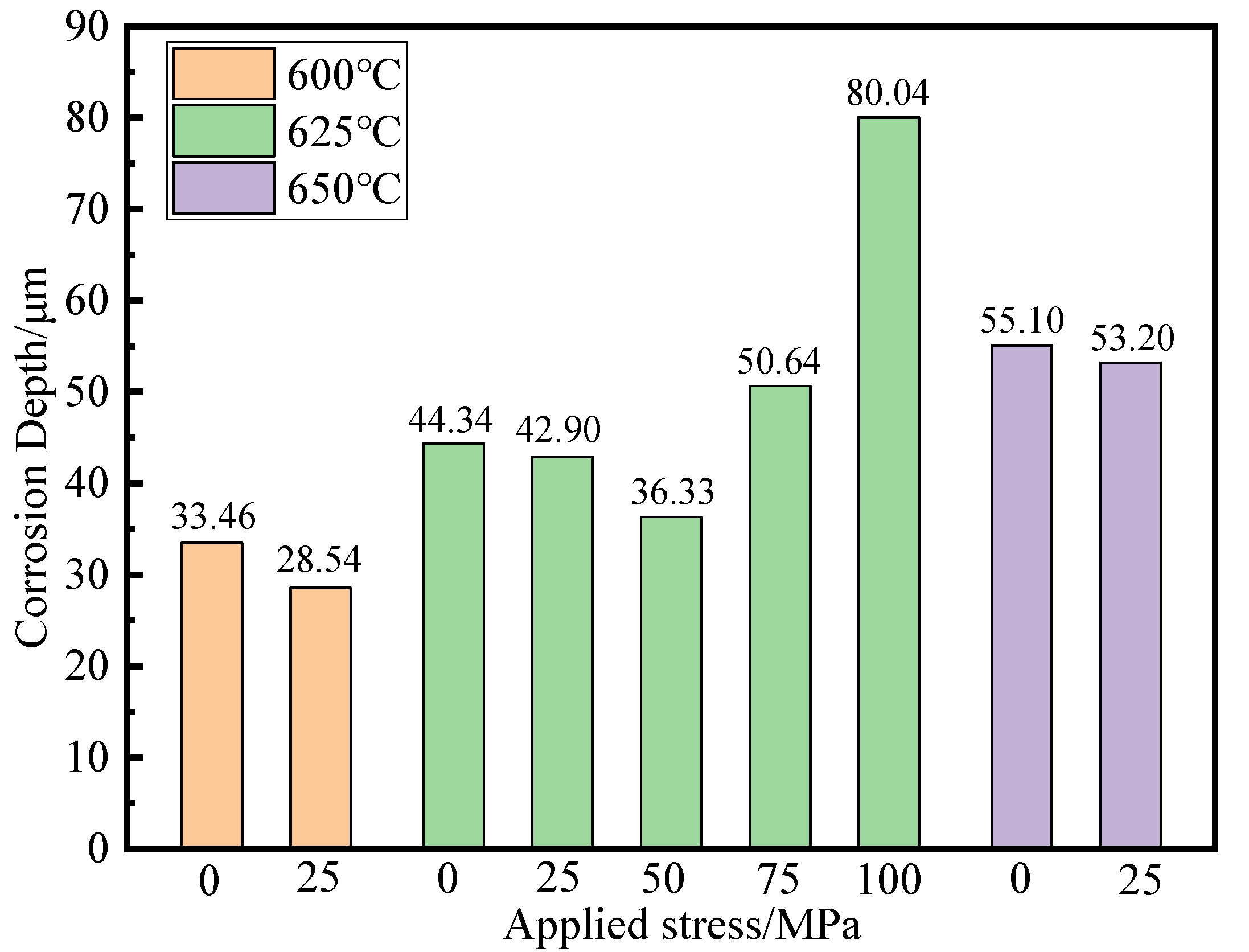
3.2. Thickness of Corrosion Layer

The thickness of the corrosion layer on the sample serves as a critical parameter for assessing the extent of material degradation due to corrosion [13,14]. These measurements on the T91 after corrosion in molten NaCl–K2SO4–Na2SO4 salt at temperatures of 600–650 °C are shown in Figure 4. A test segment measuring 1 cm in length was extracted from the standard distance section, and measurements were taken at intervals of 1 mm and averaged. As illustrated in Figure 4, at a temperature of 625 °C, the thickness of the corrosion layer exhibited an initial decrease, followed by an increase as the stress increased. Upon comparing the thickness of the corrosion layer at 600 °C and 625 °C, it was evident that an increase in temperature resulted in a corresponding increase in the thickness of the corrosion layer. This could be attributed to the faster diffusion of the ions involved in the corrosion reactions at higher temperatures. The corrosion layer thickness of the HR3C specimens decreased linearly with increasing applied stress from 0 to 60 MPa [6]. For stress levels below 50 MPa, the change in the corrosion layer thickness with respect to stress observed in this study aligns with that reported in the literature. The thickness at a pressure of 100 MPa was approximately 2.22 times greater than that observed at 50 MPa. It has been observed that the oxidation rate also exhibits a significant increase once the tensile stress exceeds a critical value [15]. A greater concentration of dislocations and defects occur in the specimens under applied stresses. These defects act as fast diffusion paths for the Cr atoms to diffuse to the surface, and thus, promote a faster formation of the protective Cr2O3 oxide layer. However, larger applied stress can also damage the integrity of the corrosion layer, resulting in an increase in the corrosion rate. A similar phenomenon was reported by Liu [16]. It has also been reported that there should be a “critical stress”, under which the specimens exhibit the best corrosion resistance.

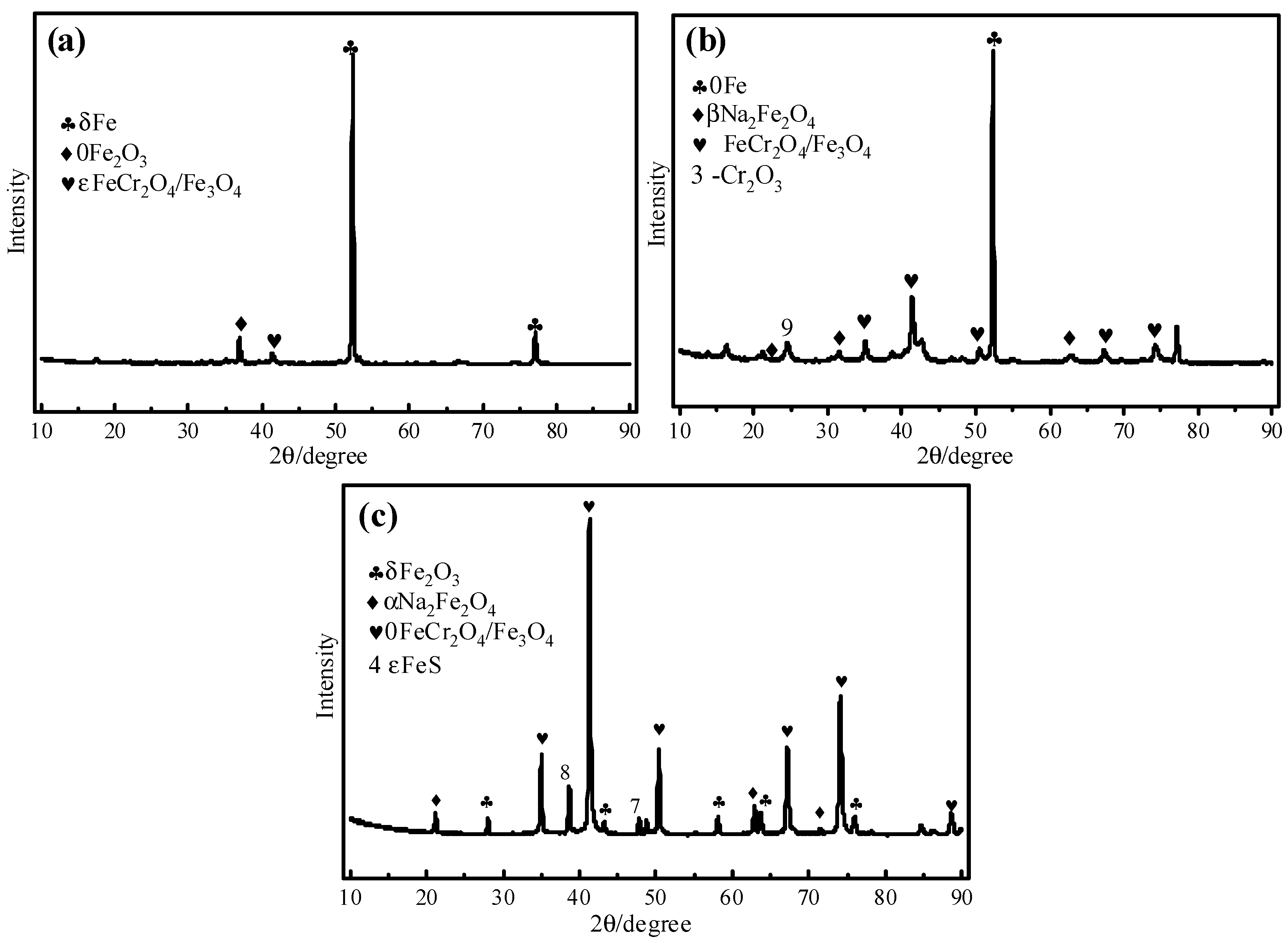
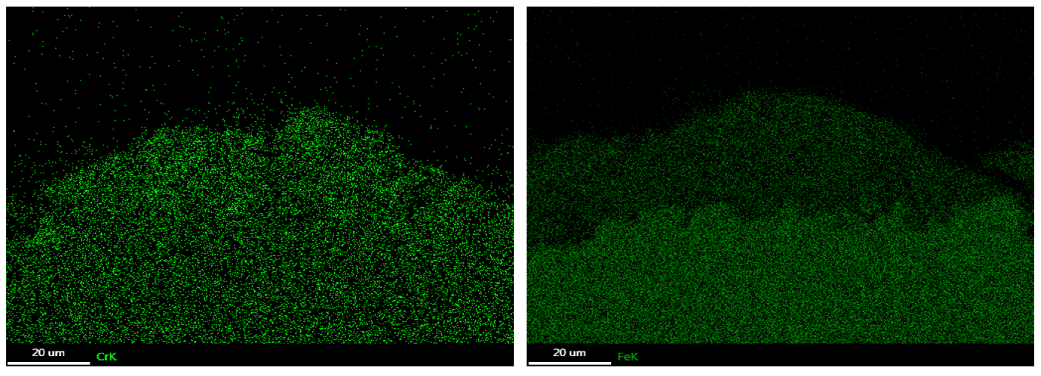
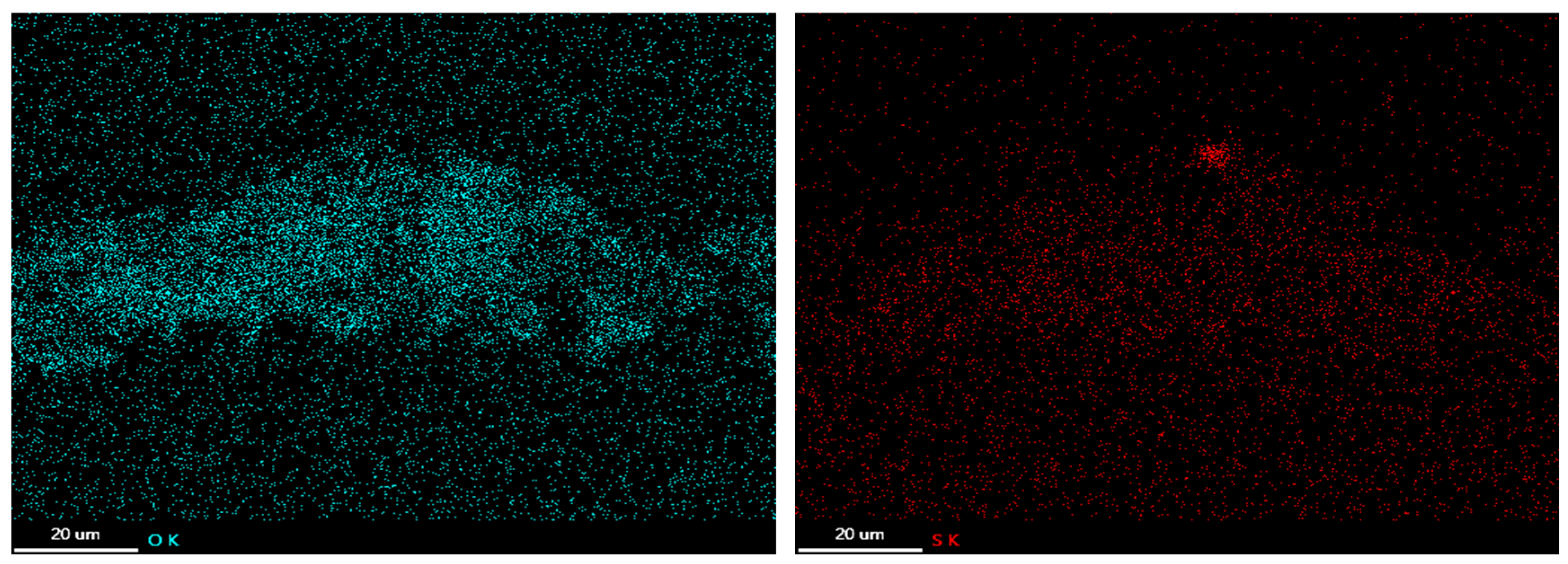
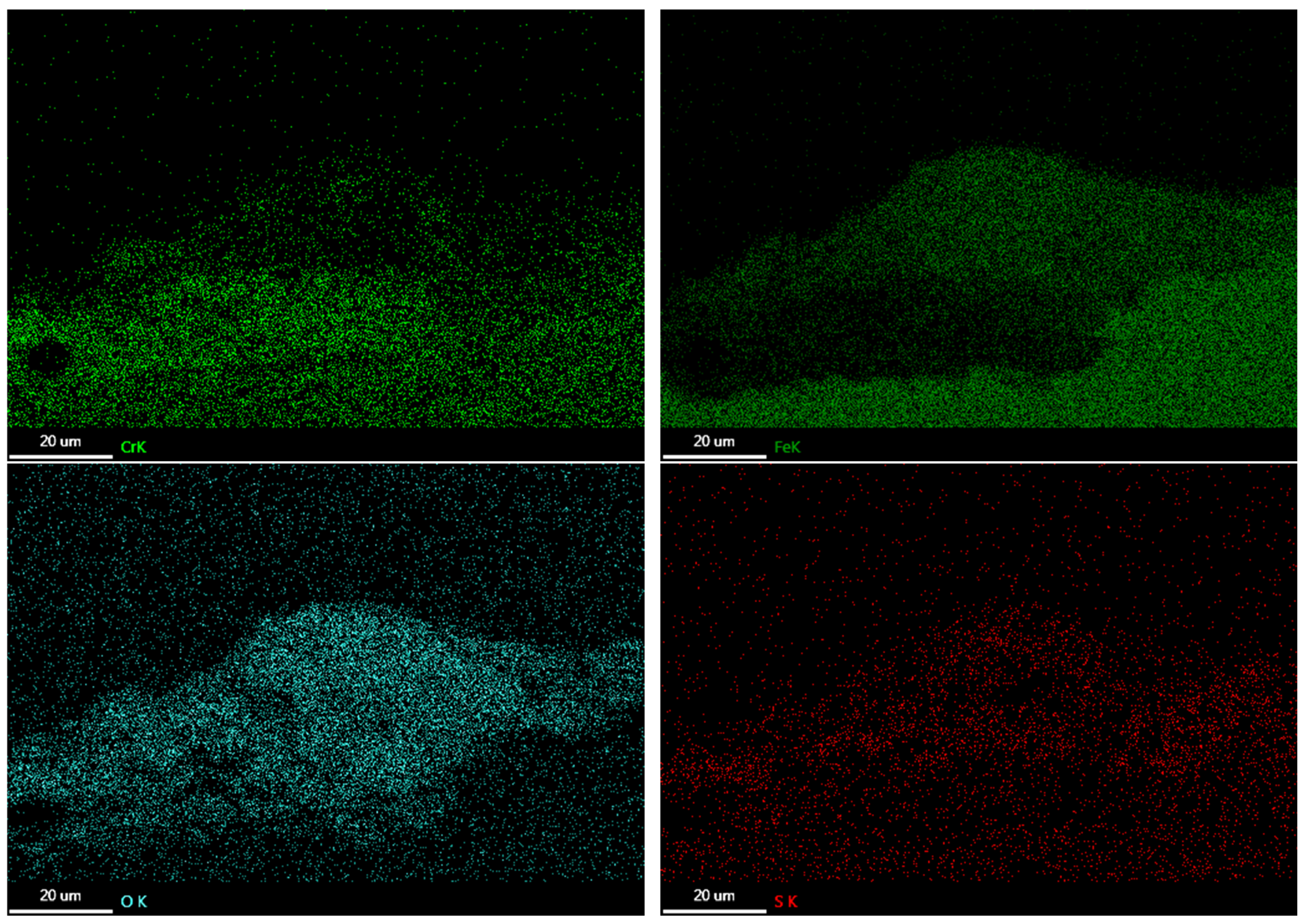
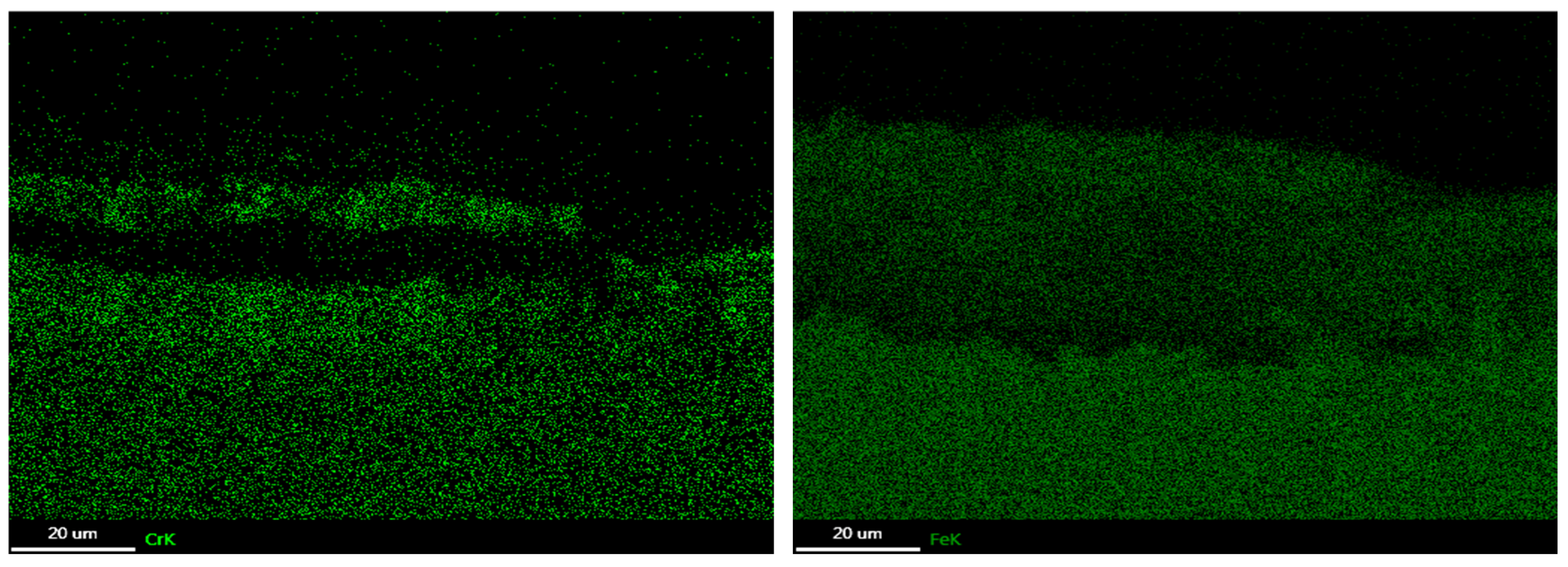
3.3. Corrosion Products

Figure 5 presents the XRD analysis results of the molten salt corrosion products at 625 °C under three different stress conditions: no stress, 50 MPa, and 100 MPa. The presence of FeCr2O4 was confirmed for all three stress conditions. The matrix phase was detected in both the no-stress and 50 MPa stress conditions. Additionally, Cr2O3, Fe3O4, and Na2Fe2O4 were identified under 50 MPa stress, while Fe2O3, Na2Fe2O4, Fe3O4, and FeS were observed under 100 MPa stress. As a protective oxide layer, Cr2O3 effectively reduces the diffusion rate of ions through the corrosion layer, thereby inhibiting the growth of the corrosion layer. Gonda [17] reported the corrosion behavior of T91 steel in a molten 75 wt% Na2SO4 + 25 wt% NaCl salt environment at 900 °C. Fe2O3, (Fe,Cr)2O3, and Cr2O3 were detected. Cr2O3 formed at 900 °C without any applied stress; this may be related to the diffusion rate of Cr3+, which is significantly influenced by temperature variations.

3.4. Oxide Morphology

Figure 6 illustrates the cross-sectional morphology of the corrosion layer and the distribution of elements under the various stress conditions at 625 °C. The microstructure of the cross-section revealed the microscopic characteristics of the corrosion layer along its thickness. The elemental distribution map displays the concentration profiles of Fe, Cr, O, and S across the thickness of the corrosion layer. When no stress was applied, the corrosion layer exhibited a relatively uniform structure. A typical duplex oxide structure was observed, which was primarily composed of an Fe-rich outer layer and an Fe/Cr-rich inner layer. The sulfur content within the corrosion layer was minimal and localized, possibly diffusing preferentially inward along grain boundaries, which increased the sulfur activity at these boundaries and led to sulfide formation [18]. The outer corrosion product was identified as Fe2O3, while the inner corrosion product was FeCr2O4. A small number of sulfides were also observed within the corrosion layer. As illustrated in Figure 6b, cracks were observed along the thickness direction within the outer layer of the corrosion layer. Sulfur was predominantly distributed in the outer layer, with minor concentrations near the interface between the corrosion layer and the matrix. Furthermore, a distinct chrome-depleted region was evident in the 20–30 μm zone.
After the stress value increased to 50 MPa, it promoted the formation of more defects in the grain boundaries, and the grains themselves enhanced the diffusion rate of Cr ions, facilitating the formation of a protective oxide layer made of Cr2O3. However, the presence of Cr2O3 subsequently inhibited the outward diffusion of iron ions, thereby reducing the growth rate of the corrosion layer [19]. Fu [20] also discovered that the application of stress induces numerous microcracks and defects, which facilitate a more rapid and efficient diffusion pathway for Cr atoms to reach the surface. This process consequently promotes the formation of a protective Cr2O3 oxide layer. Figure 6d,e show cross-sectional views of specimens subjected to stresses of 75 MPa and 100 MPa, respectively. It was evident that the corrosion layer was thicker compared to that under a stress of 50 MPa, with an increased presence of both longitudinal and transverse cracks. Notably, there was an accumulation of sulfur in the inner regions of the corrosion layer. Higher stress levels induced cracking within the corrosion layer, facilitating the ingress of sulfur through short-range pathways to form sulfides. The formation of these sulfides contributed to matrix embrittlement and crack propagation [21]. Figure 7, Figure 8 and Figure 9 present the elemental maps of T91 corroded at 600–625 °C. The Fe content of the outer corrosion layer was higher than that of the inner layer, while the distribution of chromium exhibited the opposite pattern. The gaps between the layers, which were deficient in chromium, can be observed in Figure 9. Figure 10 shows the cross-sectional microstructures and elemental maps of alloy T91 at 600 and 650 °C. It can be observed that the thickness of the corrosion layer increased with an increase in temperature. This was mostly attributed to the faster kinetics and diffusion rate at higher temperatures [22].

3.5. Corrosion Mechanism

From the element distribution of the corrosion products, it was evident that increased stress resulted in the formation of a thicker chromium-rich inner layer and an iron-rich outer layer. The underlying mechanism can be explained as follows: during the oxidation process, metal ions vacate their lattice positions, creating vacancies. The concentration of vacancies near the matrix/oxide interface differs from that at the oxide/gas interface, establishing a vacancy gradient. This gradient drives the diffusion of metal ions via the vacancy mechanism, where ions move by occupying adjacent vacancies, migrating from regions of higher concentration to lower concentration, i.e., from the matrix to the corrosion layer [23]. However, iron diffuses through the corrosion layer more rapidly than chromium, leading to the formation of iron oxides on the outer surface [24,25].
In the initial stage of corrosion, the presence of local micropores and cracks facilitates the inward diffusion of oxygen, leading to spatial variations in the oxygen concentration. The binding affinity between Cr and O is higher than that between Fe and O, so chromium oxide preferentially forms on the surface of T91. However, due to the significantly lower Cr content compared to Fe and the insufficient density of the Cr oxide layer to inhibit the outward diffusion of iron ions, a thicker iron oxide layer develops on the outer surface. As Fe/Cr oxides form, the partial pressure of O2 at the matrix/salt interface decreases, reducing local O2 partial pressures and promoting sulfate decomposition. Additionally, the deposited salt further lowers the O2 partial pressure at certain locations during the early stages of corrosion, facilitating salt decomposition [26].
Subsequently, Fe and Cr react with the decomposition products of Na2SO4 in a low O2 atmosphere to form the corresponding sulfides and oxides, as described in reactions (1) and (2). Na2O is dispersed within the sulfate layer adjacent to the sulfate/matrix interface. The sulfur released from the sulfate near the salt/matrix interface preferentially diffuses into the matrix along grain boundaries, leading to the formation of discrete sulfide particles (FeS and CrS) beneath the oxide layer via reactions (1) and (2). A low O2 partial pressure is critical for this process. Moreover, because of the existence of NaCl, reaction (3) also occurs, eliminating the protective oxides, and then the corrosive gas, Cl2, mixes with SO2 and O2 and diffuses inward to participate in the next stage of corrosion.
4Fe + Na2SO4 → 3FeO + FeS + Na2O
3Cr + Na2SO4 → Cr2O3 + CrS + Na2O
2NaCl + Fe2O3 + 1/2O2 → Na2Fe2O4 + Cl2
The applied stress significantly influences the corrosion rate by promoting the formation of a dense chromium oxide layer. Specifically, external stress induces microscopic defects in the matrix material, such as dislocations, grain boundaries, and voids. These defects alter the microstructure of the material and provide faster diffusion pathways for Cr atoms [27]. Under stress, the diffusion rate of Cr atoms increases substantially, accelerating the formation of a chromium oxide film, which effectively hinders contact between the base metal and corrosive media, thereby enhancing the material’s corrosion resistance [28,29,30]. However, as stress levels increase further, more cracks and defects develop in the metal, serving as rapid diffusion channels for chromium. While sufficient Cr can lead to quicker formation of a protective oxide layer, the limited Cr content in the alloy means that excessive grain boundaries can accelerate S diffusion. Moreover, excessive stress can compromise the integrity of the Cr protective layer, leading to increased corrosion. In the cross-sectional images, some cracks were observed in the inner corrosion layer, which was probably related to excessive deformation. Overall, it was found that tensile stress has an impact on the morphological characteristics and phase composition of corrosion products, but whether these effects are beneficial or not is dependent on the magnitude of the stress applied. Furthermore, it can be seen in Figure 4 that the thickness of the corrosion layer increased with increasing temperature under the same stress condition. Temperature had a large impact on the diffusion rate of ions along the corrosion layer. It is well known that diffusion in materials is a thermally activated process with an exponential dependence on the inverse of temperature [31]. The higher the temperature, the faster is the diffusion of ions.

4. Conclusions

The applied stresses appeared to have a large impact on the corrosion behavior of T91, and the positive and negative effects changed as the stress changed. The structure of the corrosion scale formed on T91 consisted of an outer layer of iron oxide, an inner layer of chromium oxide, and a sulfidation zone near the substrate. The thick and dense chromium oxide layer exhibited excellent corrosion resistance due to its chemical stability. A protective chromium-enriched oxide layer formed under high stress, which may be due to the faster diffusion of the chromium to the surface. However, once the stress exceeded the critical value (50 MPa), it was found to accelerate the corrosion rate.

Author Contributions

Conceptualization, K.Y. and B.S.; Methodology, K.Y.; Software, B.S.; Validation, S.M. and P.L.; Formal analysis, S.M.; Investigation, P.L.; Data curation, Z.Z.; Writing—original draft, K.Y. and S.M.; Writing—review and editing, S.M.; Visualization, Z.Z.; Supervision, S.M.; Project administration, Z.Z.; Funding acquisition, K.Y. All authors have read and agreed to the published version of the manuscript.

Funding

This work is financially supported by the Science and Technology Program of CSEI (2018youth15).

Data Availability Statement

The original contributions presented in this study are included in the article. Further inquiries can be directed to the corresponding author.

Conflicts of Interest

The authors declare no conflicts of interest.

References

  1. Viswanathan, R.; Henry, J.F.; Tanzosh, J.; Stanko, G.; Shingledecker, J. US program on materials technology for ultra-supercritical coal power plants. J. Mater. Eng. Perform. 2005, 14, 281–292. [Google Scholar] [CrossRef]
  2. Natesan, K.; Park, J. Fireside and steamside corrosion of alloys for USC plants. Int. J. Hydrog. Energy 2007, 32, 3689–3697. [Google Scholar] [CrossRef]
  3. Viswanathan, R.; Bakker, W. Materials for ultrasupercritical coal power plants-Turbine materials: Part II. J. Mater. Eng. Perform. 2001, 10, 96–101. [Google Scholar] [CrossRef]
  4. Shim, H.S.; Valentine, J.R.; Davis, K.; Seo, S.-I.; Kim, T.-H. Development of fireside waterwall corrosion correlations using pilot-scale test furnace. Fuel 2008, 87, 3353–3361. [Google Scholar] [CrossRef]
  5. Lutz, B.S.; Holcomb, G.; Meier, G. Determination of the initiation and propagation mechanism of fireside corrosion. Oxid. Met. 2015, 84, 353–381. [Google Scholar] [CrossRef]
  6. Fu, J.; Li, N.; Zhou, Q.; Guo, P. Impacts of Applied Stresses on High Temperature Corrosion Behavior of HR3C in Molten Salt. Oxid. Met. 2015, 83, 317–333. [Google Scholar] [CrossRef]
  7. Douglass, D.L.; Kofstad, P.; Rahmel, A.; Wood, G.C. International Workshop on High-Temperature Corrosion. Oxid. Met. 1996, 45, 529–620. [Google Scholar] [CrossRef]
  8. Schmitt, J.F.; Pacia, N.; Pigeat, P.; Weber, B. Study of the initial oxidation of a Ni-20Cr alloy in the temperature range 550–830 ℃: Influence of mechanical deformation. Oxid. Met. 1995, 44, 429–452. [Google Scholar] [CrossRef]
  9. Khalid, F.A.; Benjamin, S.E. The Effect of Deformation Substructure on the High-Temperature Oxidation of Inconel 625. Oxid. Met. 2000, 54, 63–71. [Google Scholar] [CrossRef]
  10. Mathieu, C.; Toesca, S. Effects of mode-I stresses on the oxidation and failure mechanisms of Ni-20Cr and Ni-15Cr-8Fe alloys in sulfur dioxide. Oxid. Met. 1993, 39, 155–165. [Google Scholar] [CrossRef]
  11. Bell, S.; Stoker, D.; Will, G.; Steinberg, T. Effects of Mechanical Stress on High Temperature Corrosion in Molten Salt. In Proceedings of the International Conference on Concentrating Solar Power and Chemical Energy Systems, Daegu, Republic of Korea, 1–4 October 2019. [Google Scholar]
  12. ASTM A213/A213M-23; Standard Specification for Seamless Ferritic and Austenitic Alloy-Steel Boiler, Superheater, and Heat-Exchanger Tubes. ASTM: West Conshohocken, PA, USA, 2015.
  13. Bai, H.; Su, C.; Xie, Y.; Zhang, B.Y.; Wang, Z.T.; Peng, X. High temperature corrosion of laser additively manufactured CoNiCrAlY. Corros. Commun. 2022, 7, 35–42. [Google Scholar] [CrossRef]
  14. Wang, J.L.; Chen, M.H.; Yang, L.L.; Sun, W.Y.; Zhu, S.L.; Wang, F.H. Nanocrystalline coatings on superalloys against high temperature oxidation: A review. Corros. Commun. 2021, 1, 58–69. [Google Scholar] [CrossRef]
  15. Calvarin-Amiri, G.; Huntz, A.M.; Molins, R. Effect of an applied stress on the growth kinetics of oxide scales formed on Ni-20Cr alloys. Mater. High. Temp. 2001, 18, 91–99. [Google Scholar]
  16. Liu, Z.H.; Ning, Z.Y.; Zhou, Q.L.; Li, N.; Liu, T.S. Effects of External Stress on High-Temperature Corrosion Behavior of T92 Ferrite Steel with Na2SO4-K2SO4 Molten Salts. Oxid. Met. 2022, 97, 141–155. [Google Scholar] [CrossRef]
  17. Gonda, D.; Chawla, V.; Puri, D.; Prakash, S. High Temperature Corrosion Behaviour of T-91 and T-22 Bare Steel in 75wt.%Na2SO4+25wt.%NaCl Molten Salt Environment at 900 °C. J. Miner. Mater. Charact. Eng. 2010, 9, 593–606. [Google Scholar]
  18. Rizhang, Z.; Manjiou, G.; Yu, Z. A study of the mechanism of internal sulfidation-internal oxidation during hot corrosion of Ni-base alloys. Oxid. Met. 1987, 27, 253–265. [Google Scholar] [CrossRef]
  19. Shang, C.G.; Xin, L.; Xu, Q.L.; Lu, Y.H. Fireside Corrosion of P92 Steel with Mixed Sulfate Deposit at 650 °C. Oxid. Met. 2020, 94, 323–341. [Google Scholar] [CrossRef]
  20. Fu, J.P.; Zhou, Q.L.; Li, N.; Liu, Z.H.; Liu, T.S. Effects of external stresses on hot corrosion behavior of stainless steel TP347HFG. Corros. Sci. 2016, 104, 103–111. [Google Scholar] [CrossRef]
  21. Young, B.D.J. High Temperature Oxidation and Corrosion of Metals; Corrosion Series; Elsevier: Amsterdam, The Netherlands, 2008; Volume 1. [Google Scholar]
  22. Hussain, N.; Shahid, K.A.; Khan, I.H.; Rahman, S. Oxidation of high-temperature alloys (superalloys) at elevated temperatures in air. II. Oxid. Met. 1995, 43, 363–378. [Google Scholar] [CrossRef]
  23. Nazarov, A.; Vivier, V.; Thierry, D.; Vucko, F.; Tribollet, B. Effect of Mechanical Stress on the Properties of Steel Surfaces: Scanning Kelvin Probe and Local Electrochemical Impedance Study. J. Electrochem. Soc. 2017, 164, 66–74. [Google Scholar] [CrossRef]
  24. Töpfer, J.; Aggarwal, S.; Dieckmann, R. Point defects and cation tracer diffusion in (CrxFe1-x)3-δO4 spinels. Solid State Ionics 1995, 81, 25–266. [Google Scholar] [CrossRef]
  25. Chen, Y.; Sridharan, K.; Allen, T.R. Corrosion behavior of ferritic-martensitic steel T91 in supercritical water. Corros. Sci. 2006, 48, 2843–2854. [Google Scholar] [CrossRef]
  26. Spiegel, M.; Schroer, C.; Grabke, H.J. Corrosion of high alloy steels and Fe-Cr-alloys beneath deposits from waste incinerator plants. Mater. Sci. Forum 1997, 251–254, 527–534. [Google Scholar] [CrossRef]
  27. Ning, Z.Y.; Zhou, Q.L.; Liu, Z.H.; Li, N.; Luo, Q.L.; Wen, D. Effects of imposed stresses on high temperature corrosion behaviour of T91. Corros. Sci. 2021, 189, 109595. [Google Scholar] [CrossRef]
  28. Calvarin-Amiri, G.; Molins, R.; Huntz, A. Effect of the application of a mechanical load on the oxide-layer microstructure and on the oxidation mechanism of Ni-20Cr foils. Oxid. Met. 2000, 53, 399–426. [Google Scholar] [CrossRef]
  29. Rahmel, A.; Wood, G.; Kofstad, P.; Douglass, D. International Workshop on “Critical Issues Concerning the Mechanisms of High-Temperature Corrosion”. Oxid. Met. 1985, 23, 253–337. [Google Scholar] [CrossRef]
  30. Barnard, B.; Liaw, P.; Buchanan, R.; Klarstrom, D. Affects of applied stresses on the isothermal and cyclic high-temperature oxidation behavior of superalloys. Mater. Sci. Eng. A 2010, 527, 3813–3821. [Google Scholar] [CrossRef]
  31. Sánchez, L.; Bolívar, F.J.; Hierro, M.P.; Pérez, F.J. Temperature dependence of the oxide growth on aluminized 9–12%Cr ferritic-martensitic steels exposed to water vapour oxidation. Thin Solid Films 2009, 517, 3292–3298. [Google Scholar] [CrossRef]
Figure 1. Schematic diagram of high-temperature molten salt test system.
Metals 15 00446 g001
Figure 2. Surface SEM images of T91 specimens under the conditions of (a) 625 °C/0 MPa, (c) 625 °C/25 MPa, (e) 625 °C/50 MPa, (g) 625 °C/75 MPa, and (i) 625 °C/100 MPa. Higher magnification views (b,d,f,h,j) of the region in the white box in (a,c,e,g,i), respectively.
Metals 15 00446 g002aMetals 15 00446 g002b
Figure 3. Surface SEM images of T91 specimens under the conditions of (a) 600 °C/0 MPa, (c) 600 °C/25 MPa, (e) 650 °C/0 MPa, and (g) 650 °C/25 MPa. Higher magnification views (b,d,f,h) of the region in the white box in (a,c,e,g), respectively.
Metals 15 00446 g003
Figure 4. Corrosion layer thickness on T91 specimens corroded under different applied stresses at 600–650 °C.
Metals 15 00446 g004
Figure 5. XRD results for different stress conditions at 625 °C: (a) 0 MPa, (b) 50 MPa, and (c) 100 MPa.
Metals 15 00446 g005
Figure 6. Cross-sectional microstructures and corresponding elemental depth profiles of T91 at 625 °C under stresses of (a) 0 MPa, (b) 25 MPa, (c) 50 MPa, (d) 75 MPa, and (e) 100 MPa.
Metals 15 00446 g006aMetals 15 00446 g006b
Figure 7. The elemental map of T91 corroded under 0 MPa at 600 °C.
Metals 15 00446 g007aMetals 15 00446 g007b
Figure 8. The elemental map of T91 corroded under 0 MPa at 625 °C.
Metals 15 00446 g008
Figure 9. The elemental map of T91 corroded under 25 MPa at 625 °C.
Metals 15 00446 g009aMetals 15 00446 g009b
Figure 10. Cross-sectional microstructures and corresponding elemental depth profiles of T91 under corrosion conditions of (a) 0 MPa at 600 °C, (b) 25 MPa at 600 °C, (c) 0 MPa at 650 °C, and (d) 25 MPa at 650 °C.
Metals 15 00446 g010aMetals 15 00446 g010b
Table 1. Chemical composition of alloy T91 (wt%).
CSiMnPSNiCrMoVNbFe
0.10.30.410.11≤0.010.078.510.920.190.07Bal.
Table 2. The elemental composition of the corrosion layer formed at 600, 625, and 650 °C under different stresses.
Element600 °C
0 MPa
600 °C
25 MPa
650 °C
0 MPa
650 °C
25 MPa
625 °C
0 MPa
625 °C
25 MPa
625 °C
50 MPa
625 °C
75 MPa
625 °C
100 MPa
O29.633.321.656.523.33330.535.39.4
S7.91.63.31.10.97.110.83.11.6
Cr1.41.13.10.82.10.81032.344.3
Fe61.1647241.673.75948.729.344.7
Disclaimer/Publisher’s Note: The statements, opinions and data contained in all publications are solely those of the individual author(s) and contributor(s) and not of MDPI and/or the editor(s). MDPI and/or the editor(s) disclaim responsibility for any injury to people or property resulting from any ideas, methods, instructions or products referred to in the content.

