Article

Thermomechanical Behavior and Experimental Study of Additive Manufactured Superalloy/Titanium Alloy Horizontal Multi-Material Structures

by
Yanlu Huang
1,*,
Tianyu Wang
1,
Linqing Liu
1,
Yang Li
1,
Changjun Han
1,
Hua Tan
2,
Wei Zhou
3,
Yongqiang Yang
1 and
Di Wang
1,*
1
School of Mechanical and Automotive Engineering, South China University of Technology, Guangzhou 510641, China
2
State Key Laboratory of Solidification Processing, Northwestern Polytechnical University, Xi’an 710072, China
3
Department of Mechanical & Electrical Engineering, Xiamen University, Xiamen 361101, China
*
Authors to whom correspondence should be addressed.
Metals 2025, 15(4), 454; https://doi.org/10.3390/met15040454
Submission received: 16 March 2025 / Revised: 15 April 2025 / Accepted: 16 April 2025 / Published: 17 April 2025

Abstract

:
In laser powder bed fusion (LPBF) forming multi-material structures, the thermal stress mismatch caused by the different thermophysical properties of different materials can cause interface cracking and delamination defects. An in-depth investigation of the complex interfacial thermomechanical behavior caused by it is of great significance for reducing stress concentration, suppressing defects, and enhancing interfacial bond strength. In this study, the effects of scanning strategy and interface shape on the temperature distribution, thermal cycling, and thermal stress distribution at the interface are analyzed by the IN718-Ti6Al4V horizontal multi-material thermally coupled finite element model. The results show that the 45° scanning strategy is helpful for the uniform distribution of energy and the reduction of overheating and residual stress concentration. The maximum residual stress at the interface in the Ti6Al4V/IN718 structure is more than 700 MPa, which is higher than that in the IN718/Ti6Al4V structure. The first formation of Ti6Al4V will likely lead to higher residual stresses at the interface, which are difficult to release in subsequent printing. The analysis of different interface shapes shows that different interface shapes change the crack formation and extension paths. This study contributes to an in-depth understanding of improving the strength of horizontal multi-material interfacial bonding at the LPBF forming. It provides a reference for optimizing LPBF forming of difficult-to-bond materials.

1. Introduction

A multi-material structure is a material that varies in three dimensions and consists of two or more materials with varying compositions [1,2]. Compared with single-material structures, multi-material structures can use specific materials at specific locations to meet the physical and chemical performance requirements and are widely used in aerospace, automotive, and other fields [3,4]. IN718 is a nickel-based high-temperature alloy that is resistant to high temperatures and corrosion, and has excellent tensile strength, creep resistance, and antioxidant properties at elevated temperatures [5], and is widely used in aerospace and aeronautics in high-temperature component manufacturing. Ti6Al4V has a low density and high specific strength [6,7] and is commonly used in lightweight aerospace components. Integrating these two materials into a single part can combine their advantages. For example, IN718 is used for internal high-temperature resistance for engine gas generator piping, while Ti6Al4V is used for external low temperature, which reduces component mass and ensures sufficient strength. However, aerospace components (such as turbine blades, gas generator pipes, etc.) have complex structures and traditional manufacturing processes such as welding, powder metallurgy, etc., and it is not easy to directly manufacture a variety of material layouts and structural complexity of multi-material parts. Additive manufacturing (AM) technology can directly form multi-material metal components with complex geometries and multiple material layouts [8,9,10]. Directed energy deposition (DED) and laser powder bed fusion (LPBF) technologies are typical for the additive forming of metallic multi-material structures.
When forming multi-material structures, the difference in thermophysical properties between two materials at the interface is a key factor leading to interfacial defects. During the additive manufacturing process of multi-material structures, the significant differences in thermophysical properties (e.g., thermal conductivity, melting point, thermal expansion coefficient) between different materials make the complex thermomechanical behavior at the interface prone to stress concentration and interfacial defects [11]. Repeated fast heating and cooling during forming produces significant residual stresses, leading to interface cracking and deformation [12]. The literature studies the additive manufacturing process, microstructure, and mechanical properties of multi-material structures of nickel-based high-temperature alloy/titanium alloy. Shah [13] et al. used the DED process to deposit a nickel alloy on Ti6Al4V, which resulted in high interfacial stresses and cracking due to the generation of TiNi brittle-phase compounds at the interface as well as the difference in the coefficients of thermal expansion of the two materials and other properties. However, the existing literature focuses on the interface microstructure and properties of Ni-based high-temperature alloy/titanium alloy multi-material structures formed by DED or welding, and there are few reports on such structures formed by LPBF, especially for horizontal multi-material studies. It should be noted that the smaller melt pool and higher cooling rate during LPBF forming can exacerbate the elemental diffusion inhomogeneity and the formation of defects (e.g., cracks). In addition, the current literature on multi-material LPBF is mainly concerned with the microstructure and bonding properties of the interfaces. In contrast, the thermomechanical behavior at the interfaces of different materials during the LPBF process is understudied.
An in-depth investigation of the interfacial thermomechanical behavior is crucial for revealing the interfacial bonding mechanism and controlling the interfacial deformation or stress concentration. In the process of laser powder bed fusion (LPBF) forming of multi-material structures, the existence time of the melt pool is extremely short [14], during which complex physicochemical reactions occur rapidly, which makes it extremely difficult to obtain key information such as temperature, stress, and strain during the forming process by traditional experimental means. Moreover, experimental methods are often time-consuming and costly. In contrast, numerical simulation using finite elements has become an efficient way to study the interfacial thermomechanical behavior during LPBF forming of multi-material structures. Numerical simulation can more efficiently study and analyze the interface temperature distribution and stress evolution law than experiments. Chen [15] et al. constructed a thermomechanical coupling model of TiB2/Ti6Al4V multi-material and analyzed the temperature of the Ti6Al4V layer, the temperature gradient, and other parameters in the LPBF process in depth. The simulation results show that the temperature of the molten pool and the liquid lifetime significantly affect the melt wetting, which in turn further plays a role in the wetting of the molten pool. This further acts on the metallurgical bonding effect at the interface, and good interfacial bonding between TiB2 and Ti6Al4V has been successfully achieved. Huang [16] et al., on the other hand, established a thermomechanical coupling model of Ti6Al4V/AlMgScZr. Through numerical simulations, it was found that the elemental diffusion was alleviated with the improvement of the scanning speed of AlMgScZr. Thus, the formation of metal compounds and stress concentration phenomena were reduced, effectively avoiding cracks. Mao [17] et al. constructed a thermomechanical coupling model for CuCrZr/316L. She thoroughly investigated the influence of process parameters on the thermal distribution and residual stress at the interface of multi-materials. The results showed that the faster the scanning speed, the greater the residual stress, and the maximum residual stress appeared at the interface of CuCrZr/316L, resulting in many cracks at the interface. However, the current numerical simulation studies of multi-materials mainly focus on the thermomechanical behavior of vertical multi-material interfaces, and the influence of the thermomechanical behavior of horizontal interfaces has not been reported.
This paper establishes a finite element model for thermomechanical coupling of horizontally oriented non-homogeneous materials. The effects of scanning strategy and interface shape on the temperature distribution, temperature gradient, and residual stress evolution at the interface during the process of LPBF forming of Ti6Al4V/IN718 heterogeneous materials are studied through numerical simulation to deeply explore the effects of different scanning strategies and interface shapes on the thermo-physical and mechanical behavior mechanisms of the interface of multi-material. The aim is to profoundly investigate the effects of different scanning strategies and interface shapes on the thermophysical and mechanical behavior of multi-material interfaces and to reveal the thermomechanical behavior of heterogeneous material interfaces to provide a theoretical basis for the formation of well-bonded and high-performance IN718/Ti6Al4V horizontal multi-material.

2. Finite Element Model

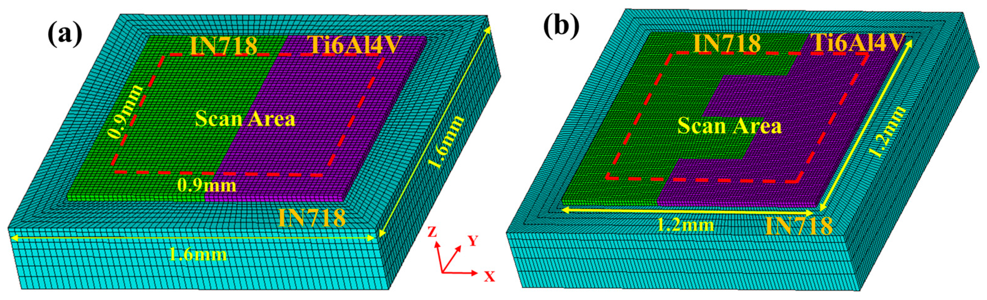
2.1. Establishment of Finite Element Model and Assumptions

In this paper, the finite element simulation model is built using the ANSYS Parameter Design Language (APDL) with the ANSYS software (2022R1, ANSYS, Pittsburgh, PA, USA). The geometric model is divided into two parts from bottom to top: the substrate and the powder layer. The dimensions of the substrate are 1.6 × 1.6 × 0.3 mm3 and those of the powder layer are 1.2 × 1.2 × 0.03 mm3. The scanning area is 0.9 × 0.9 mm2, and the thickness of each powder bed layer is 0.03 mm thick. In previous laboratory studies, IN718 formed on Ti6Al4V was more prone to cracking, so the substrate in this study was made of IN718. To improve the calculation efficiency, the mesh size of the powder layer is 0.015 × 0.015 × 0.015 mm3. In our study, the substrate’s grid division adopts the mapping grid division method, and the mesh size increases from top to bottom, with an increase coefficient of 1.5. This method can improve computation efficiency and ensure computation accuracy. The model mesh is shown in Figure 1. The multi-material structures in this work mainly include two types: (i) IN718/Ti6Al4V multi-material structure with direct bonding of IN718 and Ti6Al4V, as shown in Figure 1a; (ii) Multi-material structure of IN718/Ti6Al4V with different interface structures, as shown in Figure 1b. Different materials are connected in joint element mode, and the continuity of displacement and strain is ensured by sharing nodes, thus improving the calculation accuracy and efficiency of the model. In the numerical simulation, the layer-by-layer build-up process during LBPF is simulated using the life-death element technique [18]. The powder layers that are not included in the calculation are in a ‘dead’ state and do not affect the calculation results during the calculation. In the simulation laser scanning, each calculation step will load the corresponding heat flow according to the material type of different units to ensure the accuracy of heat source loading. The following assumptions are made for the model to simplify the calculation while ensuring calculation accuracy appropriately.
The entire powder bed is assumed to be a continuous homogeneous medium. However, this simplification may underestimate changes in heat transfer because the actual powder bed is composed of discrete powder particles, whose heat conduction properties may vary depending on the contacts and voids between the particles. We minimize the impact by separately defining material parameters for powder and solid states.
Materials’ thermal and mechanical properties change with temperature, while the convective heat transfer and thermal radiation coefficients are considered fixed values [19] and do not change with temperature.
The laser beam’s energy input to the powder bed assumes a Gaussian heat flow distribution, with intensity decreasing with depth.
Evaporation during the powder melting process and melt pool flow are neglected, and the change in thermal conductivity and enthalpy represents the change in the material’s phase state.

2.2. Temperature Field Control Equations

The LPBF forming process is typically a nonlinear transient heat transfer process, where the laser energy is applied instantaneously to the surface of the powder bed to form a high-temperature melt pool. The heat in the molten pool is transferred to the cured area and the underlying powder mainly through heat conduction. At the same time, some of the heat is also dissipated to the surrounding environment through thermal radiation. The nonlinear transient heat transfer equation can describe this process [20]:
ρ c P T t = x k T x + y k T y + z k T z + Q
where ρ is the density of the material (kg/m3); Cp is the specific heat capacity of the material (J/kg·K); T is the temperature of the material (K); t is the time (s); Q is the strength of the heat source in the unit; k is the thermal conductivity of the material (W/(m·K)).
The initial condition is the initial temperature in the computational domain at t = 0. The initial temperature T0 = 293 K in this calculation:
T ( x , y , z , t ) t = 0 = T 0
The thermal boundary conditions are as follows:
The heat input to the powder bed is loaded in the form of a heat flux density:
k T n = q s ( x , y , z )
where n is the direction of the normal outside the boundary. Boundary conditions for convective heat transfer and heat radiation between the model and the outside:
k T n + q c = 0
where qc is thermal convection:
q c = H c T T 0
where Hc is the composite heat transfer coefficient, which considers both heat radiation and heat convection to simplify the model and reduce the amount of calculation:
H c = h c   + σ S B ε T 2 + T 0 2 T + T 0
where σSB is the Stefan-Boltzman constant, which has a value of 5.67 × 10⁻⁸ W/(m2∙k4); and ε is the emissivity of the powder. In numerical simulations, convective heat transfer is loaded on all nodes of the entire surface of the model (except the bottom surface).
In the LPBF process, the latent heat of the material’s phase change cannot be neglected, and its influence on the temperature field is significant. In ANSYS, the latent heat of phase change is handled by defining the enthalpy of the material, the enthalpy [21]:
H = ρ C v d T

2.3. Heat Source Modelling

The laser acts on the powder bed, and its laser intensity distribution is approximated as a Gaussian distribution. The Gaussian body heat source model is used in this paper to describe this process. The model takes into account the reflection of the laser inside the powder bed and assumes that the laser intensity decreases with increasing depth, which is more in line with the laser energy distribution in the actual forming process [22]. The heat source model is expressed as:
q s = 2 A P π r 2 η exp 2 x x 0 V s c a n t 2 + y y 0 2 r 2 exp | z | η
where qs is the laser energy density; A is the absorption rate of the material to the laser; P is the laser power (W); r is the spot radius of the laser (mm); η is the action depth of the laser (mm), in this paper, we take the thickness of the single-layer powder bed; x0, y0 are the coordinates of the center point of the laser in the moving heat source at time t, and the heat flux of the point with coordinates (x, y) is calculated by the distance from it; Vscan is the laser scanning speed.

2.4. Stress Field Governing Equations

In the finite element model, we used the thermal-mechanical indirect coupling method. Specifically, we first calculate the temperature field through thermal analysis and then input the temperature field into the stress field as a load for stress calculation, and all nodes on the bottom surface of the substrate are fixed with six degrees of freedom as constraints. The stresses are following Equation (9) [23]:
{ σ } = [ D ] ε e
where {σ} is the stress tensors; [D] is the elastic matrix; and {εe} is the elastic strain tensors, which can be expressed as:
ε e = { ε } ε t h
where {ε} is the total strain; {εth} is the thermal strain, which can be expressed as:
ε t h = α e Δ T = T r e f T α ( T ) d T
where αe is the coefficient of thermal expansion; Tref is the reference temperature, the temperature in the initial conditions. It can be obtained from Equations (9) and (10):
{ ε } = [ D ] 1 { σ } × ε th
For isotropic materials, the stress-strain relationship is:
ε x x = 1 E σ x x × μ σ y y + σ z z + α e Δ T ε y y = 1 E σ y y × μ σ x x + σ z z + α e Δ T ε z z = 1 E σ z z × μ σ x x + σ y y + α e Δ T ε x y = 1 + μ E σ x y , ε x z = 1 + μ E ε x z , ε y z = 1 + μ E ε y z
where E is the modulus of elasticity of the material; μ is the Poisson’s ratio of the material; and ΔT denotes the temperature rise at a point (x, y, z) at time t concerning time t = 0.
During the LPBF process, the material receives the heat source to expand and shrink sharply when it cools down. The materials are internally constrained to each other, thus generating thermal stresses, and plastic deformation usually occurs at high temperatures. Specifically, when a material is stressed at high temperatures, its yield strength is significantly reduced, making it more prone to plastic deformation. This plastic deformation is critical to understanding how the material behaves during the LPBF process, as it can affect the final part’s mechanical properties and dimensional stability. In the finite element simulation, the plastic deformation of the material follows three main criteria: yield criterion, flow criterion, and reinforcement criterion [24].
Where the yield criterion is used as a criterion for determining whether a material has reached its yield limit and thus entered plasticity, in the stress field calculations, the Von Mises yield criterion, i.e., the equivalent stress yield criterion, is used, and its expression is:
σ e q ν = 1 2 σ 1 σ 2 2 + σ 2 σ 3 2 + σ 3 σ 1 2
where σ1, σ2, σ3 are the first, second, and third principal stresses. This paper’s material yield deformation process obeys the Von Mises yield criterion.
The flow criterion describes the direction of strain when the material yields and can be expressed as:
{ d ε } p = { d λ } σ e q ν { σ }
where {}p is the plasticity increment; {} is the plasticity factor; σ e q ν { σ } is the bias of σeqv on {σ}.
The strengthening criterion describes how the yield surface changes with plastic deformation and is divided into isotropic hardening and kinematic hardening. Isotropic hardening means that the center of the yield surface remains unchanged when the material yields but expands uniformly in all directions, while kinematic hardening implies that the size and shape of the yield surface remain unchanged, but its center is displaced. In this paper, a bilinear kinematic hardening model is used to simulate the yielding behavior of the material more accurately.

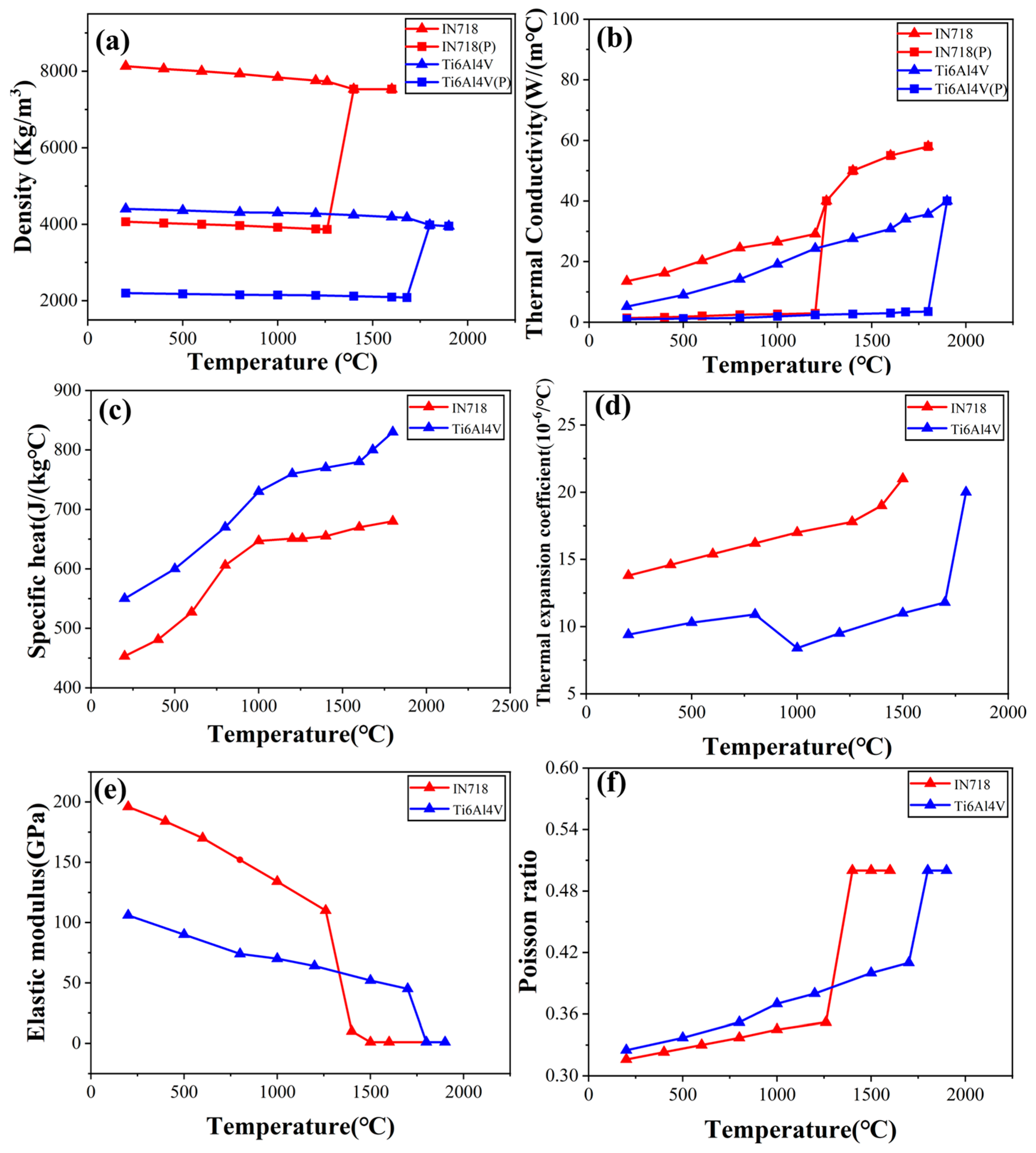
2.5. Material Properties
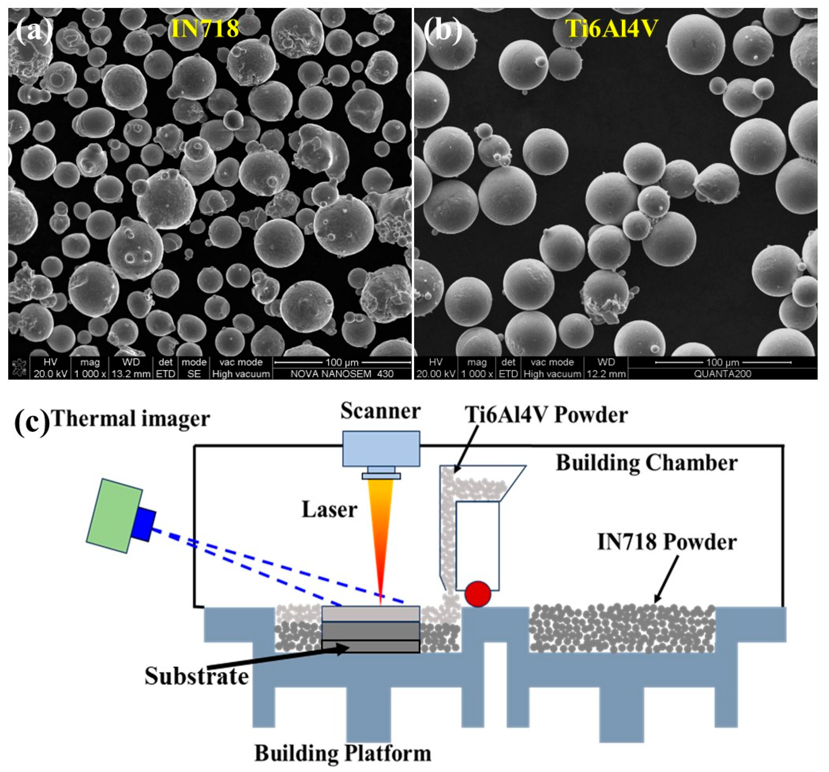
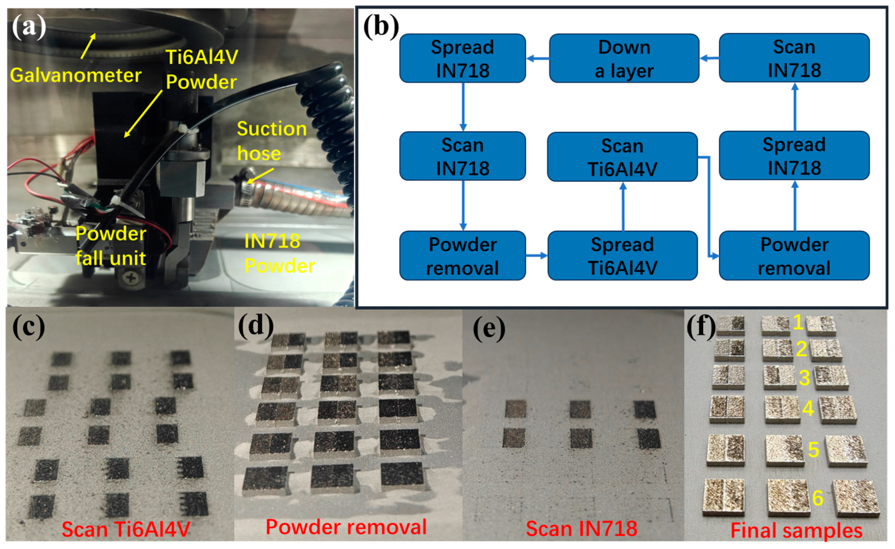
The thermophysical parameters of powders are very different from those of solids, especially the thermal conductivity, which significantly affects the numerical simulation results. During the simulation process, the material is in the powder state when the temperature of the element is below the melting point. At the same time, it transforms into a solid when the temperature is above the melting point and remains solid thereafter. The thermal conductivity of the powder material is closely related to the porosity of the powder bed [25]:
k p o w d e r = k s o l i d ( 1 ϕ )
where kpowder, ksolid are the thermal conductivity in powder and solid state, respectively, and ϕ is the porosity of the powder bed, which is calculated by Equation (17):
ϕ = ρ s o l i d ρ p o w d e r ρ s o l i d
where ρsolid and ρpowder are the densities of the material in powder and solid state, respectively, in this paper. The material properties in the numerical simulation were calculated using JMatPro software (Version 7.0, Sente Software, Guildford, UK) and corresponding references. The material parameters of IN718 [26] and Ti6Al4V [27] are shown in Figure 2, where Figure 2a–d shows the thermophysical parameters of the material, and Figure 2e,f shows the mechanical parameters of the material, and other parameters in the numerical simulation in this paper are shown in Table 1.

3. Experimental

The materials used in this experiment include gas atomized spherical IN718 (Avimetal powder metallurgy technology Co., Ltd., Beijing, China), Ti6Al4V (APC Powder Metallurgy, Montreal, Quebec, Canada) alloy powders. In Figure 3a,b, the SEM images of the two powders are shown, respectively, and the particle sizes distribution of the powders are all 15–53 μm. The tests in this paper were conducted using a DiMetal-100H model LPBF forming machine (laseradd, Zhuhai, China) with a modified powder laying cart to form horizontal multi-material, which was equipped with a powder cylinder and a drop hopper, respectively, for supplying different kinds of powders (Figure 3c). The building platform can be raised and lowered. We need to fix the substrate (IN718) on it by bolts and then shape it. For supplying different kinds of powders, IN718 powder is stored in the powder cylinder, and Ti6Al4V powder is stored in the powder drop hopper on the powder laying car (the powder drop can be controlled by controlling the switch of the powder drop hopper). By alternating the powder laying of the two kinds of materials, a multi-material structure in which the material varies in a horizontal direction can be formed by the direct LPBF. In the process of LPBF forming, argon is used as a protective gas in the forming chamber. In addition, the surface morphology was observed using a VHX-5000 super depth-of-field microscope (keyence, Guangzhou, China) after the forming process was completed. Then, the parts were separated from the substrate using a wire-cutting machine, embedded and polished, and the interfaces of the formed parts were observed using a LEICA DMIRM metallurgical microscope (Leica, Guangzhou, China) to analyze the interfacial defects and features.

4. Results and Discussion

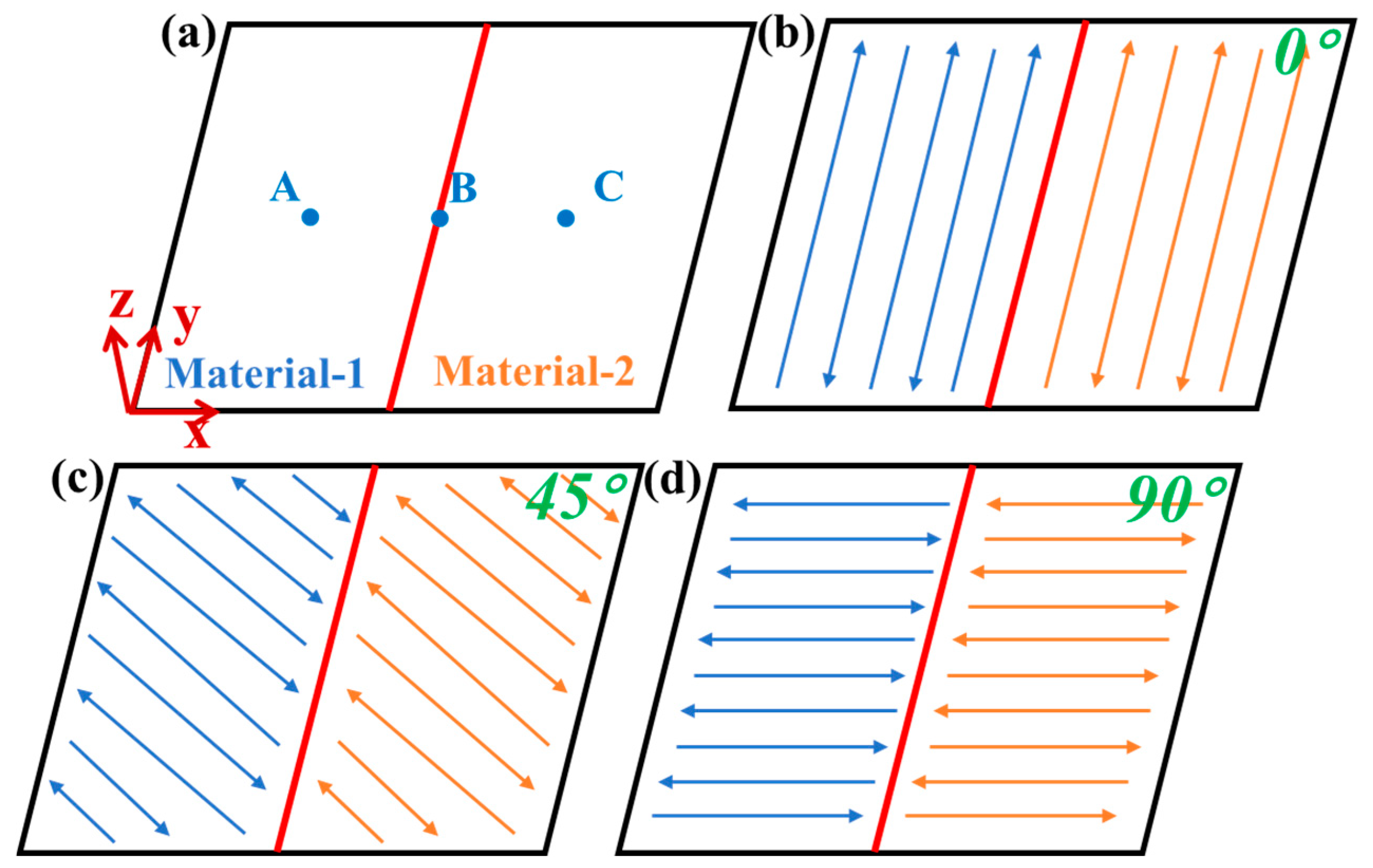
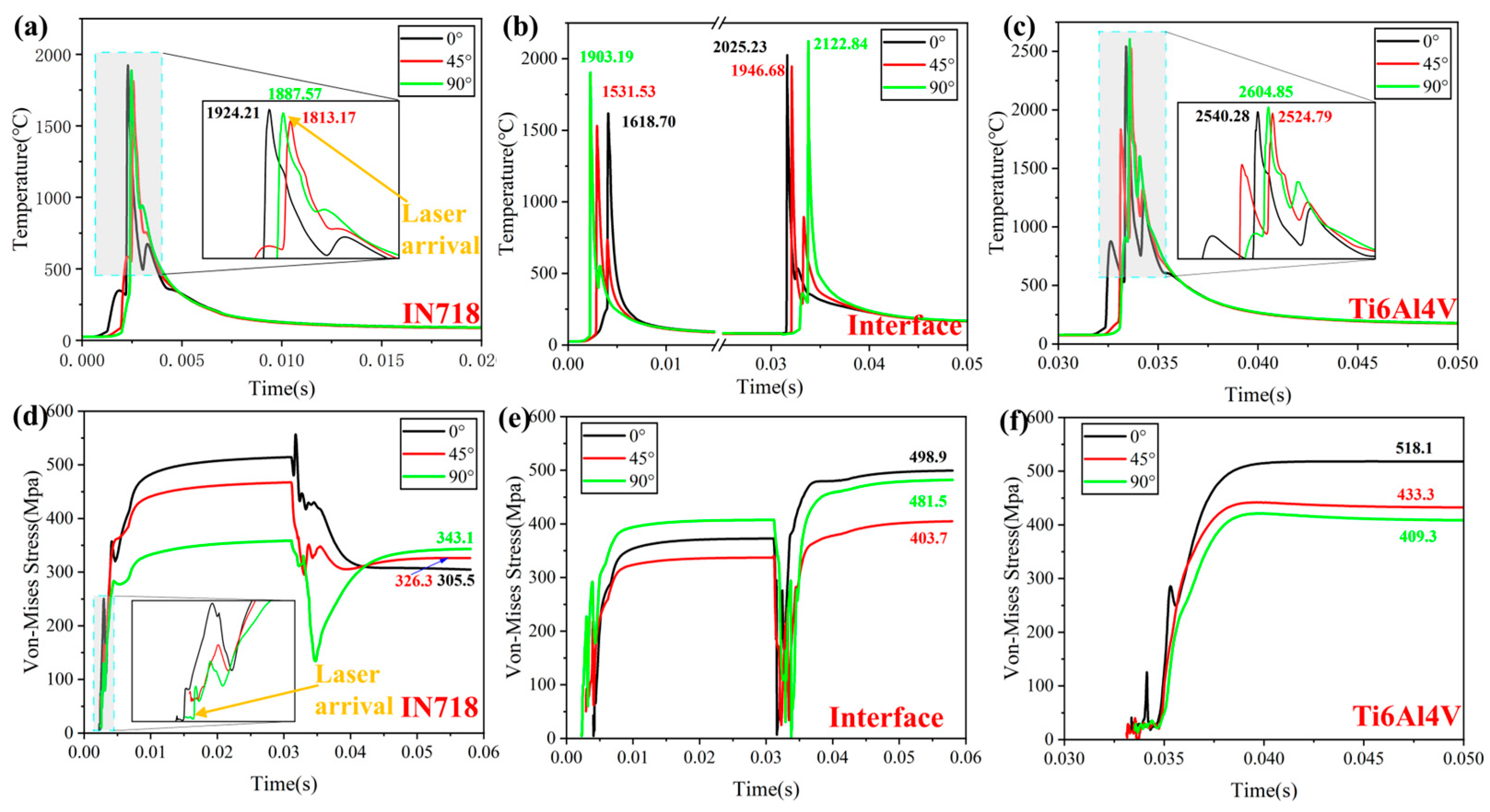
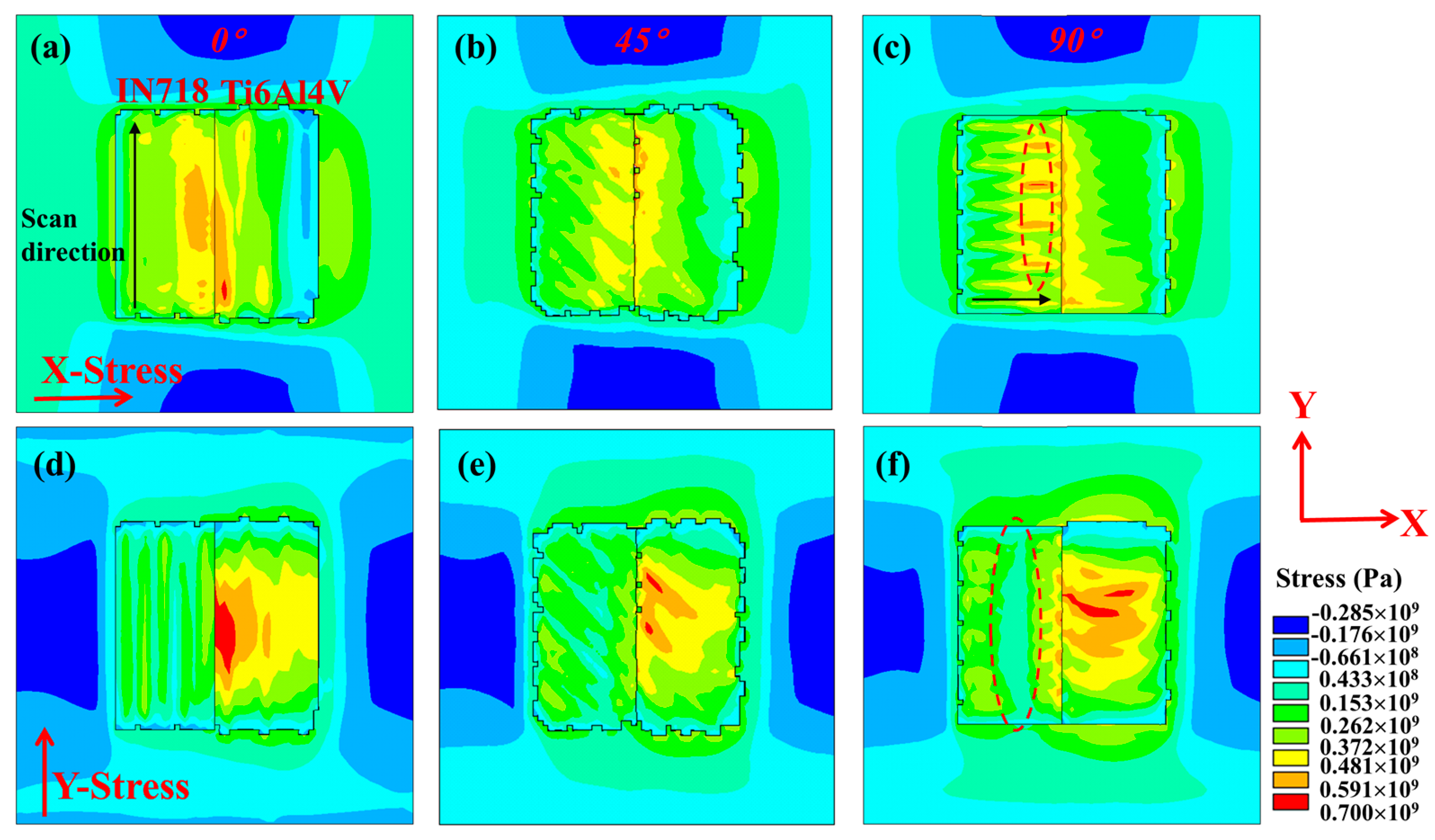
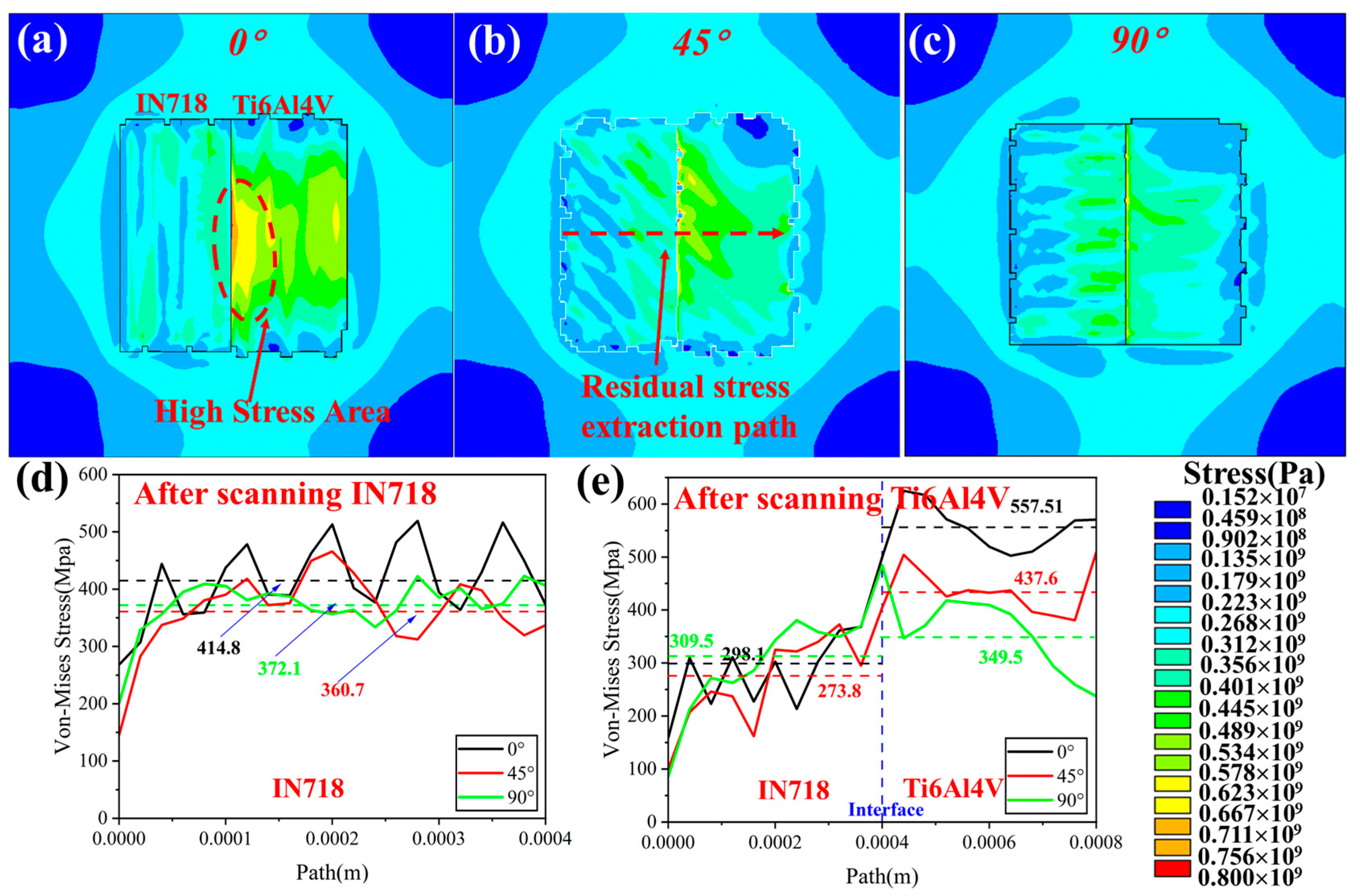
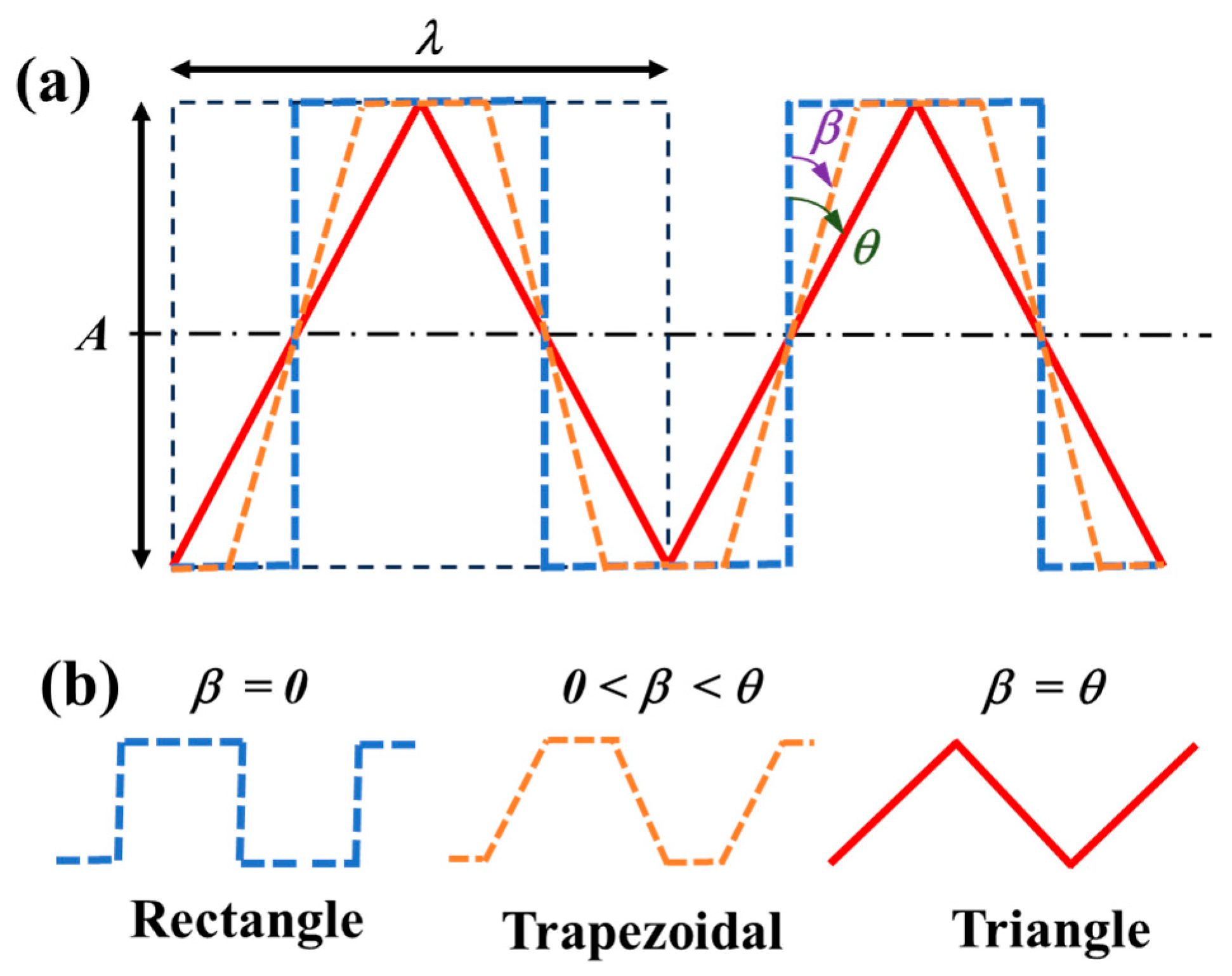
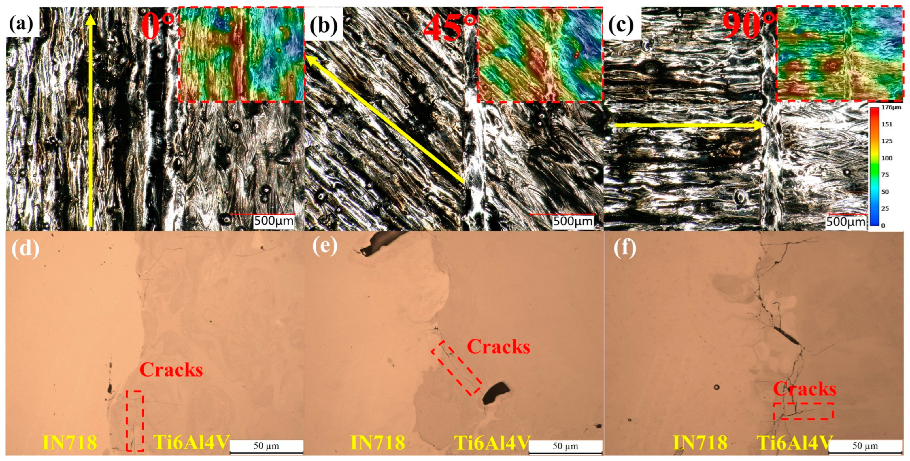
4.1. Effect of Scanning Strategy on Thermomechanical Behavior

In horizontal multi-material structures, a suitable scanning path can optimize the cooling rate and reduce the temperature gradient at the interface, thus improving the bond strength of the interface. This paper investigates the effects of three different scanning strategies on the thermomechanical behavior near the interface, according to the angles of 0°, 45°, and 90° between the scan line and the horizontal interface, as shown schematically in Figure 4b–d. In order to better investigate the thermomechanical behavior, three characteristic point A, B, and C, are extracted for different materials and near the interface, respectively, as shown in Figure 4a. The coordinates are (0.3 mm, 0.6 mm), (0.6, 0.6), (0.9, 0.6), respectively, and the coordinates of the scanning starting points of different scanning strategies are (0.15 mm, 0.19 mm), (0.2, 0.15), (0.19, 0.15), respectively. They are all located above the powder bed, i.e., the z coordinate is 0.03 mm. The three feature points are located on one side of the IN718 material, the interface, and the symmetric position on the Ti6Al4V material. The study of the thermal stress cycle by extracting nodes near feature points is to capture the key behavior of materials under cyclic load more comprehensively. In addition, the feature points can help us better understand the residual stress distribution and stress concentration of materials under cyclic load.
Numerical simulations of horizontal IN718/Ti6Al4V multi-material under different scanning strategies are carried out. The resultant data for extracting the characteristic points in the temperature and stress fields are shown in Figure 5. Figure 5a–c shows the temperature cycling diagrams of the characteristic points, the peak temperature occurs when the laser reaches the change point. At this time, the peak temperature is higher than the material’s melting point, which is due to the simplified treatment of evaporation and molten pool flow during the powder melting process in the numerical simulation. These processes take away heat in practice, but due to the simplification of the model, the heat dissipation is not timely, resulting in simulated temperatures higher than the melting point. It can be found that the peak temperature is the lowest at 45° angle when scanning IN718, and the highest at 90°, which is caused by the shorter scanning line at this time, and the more significant thermal cumulative effect. A similar pattern can also be found in the scanning process of Ti6Al4V. However, the peak temperature is about 35% higher than that of other materials, mainly due to the different material properties and process parameters of Ti6Al4V. Ti6Al4V has lower thermal conductivity and higher specific heat capacity, and the energy density of the laser is higher, which makes the temperature rise of Ti6Al4V more significant. The low thermal conductivity limits the rapid diffusion of heat, so the temperature is greatly affected by adjacent scanning channels [28]. At the interface, the temperature cycle shows that the second peak temperature is higher than the first peak temperature. This is due to the low thermal conductivity of Ti6Al4V, which limits the rapid diffusion of heat, and the high energy density of the laser. This point is more affected by thermal accumulation, so the peak temperature has increased. It should be noted that in the laser melting process, the cumulative effect of heat is indeed a key factor. When the deposition thickness increases, the heat diffusion path becomes longer, and the heat is more easily distributed evenly inside the material, thus making the heat accumulation effect stable. In our study, because the model is small and the heat diffusion path is limited, the heat accumulation effect is obvious. This phenomenon is particularly significant in Ti6Al4V. The peak temperatures at the interface are above the melting points of the two materials, where remelting of the materials occurs, which facilitates interfacial bonding.
In LPBF, local areas of the material heat up rapidly due to the absorption of laser energy, resulting in thermal expansion. As the laser moves, the melting area cools rapidly, and the material contracts, resulting in thermal stress, and temperature gradient is one of the key factors in the generation of thermal stress. The temperature difference between the center of the molten pool and the surrounding area can cause uneven thermal expansion and contraction, resulting in thermal stress [29]. When a temperature gradient is inside the object, the high-temperature part expands more, and the low-temperature part expands less. This difference leads to the formation of stress inside the material. If the temperature gradient is large and the stress exceeds the yield strength of the material, cracks may occur [30]. For example, in Ti6Al4V, the heat accumulation effect is more obvious. Although the heat accumulation will lead to an increase in the average temperature, the rapid accumulation of heat in the local area may lead to the formation of local high-temperature areas, thus aggravating the temperature gradient. This results in higher thermal stress. Residual stress is the specific state that remains inside the material after the action of these stresses. Therefore, the study of residual stress contributes to the in-depth understanding of the long-term effects of thermal behavior and provides an important reference for optimizing material properties in practical engineering applications.
Figure 5d–f shows the stress cycle diagrams of the characteristic points when scanning IN718 and Ti6Al4V, respectively; when the laser does not reach the change point, the material state is a powder state, so there is no thermal stress; the beginning of the curve is when the laser reaches the change point. The smaller the angle of the scanning strategy, the greater the residual stress. Long scan lines cause heat to be input for a longer time in a local area, which exacerbates the heat accumulation effect. This cumulative effect causes the material to experience greater temperature changes and temperature gradients during the laser scanning process, which in turn generates greater residual stress. The largest residual stress exceeds 500 MPa, then the stress decreases under the thermal influence of Ti6Al4V, and finally, the residual stress decreases with the increase in angle. Combined with the temperature cycle, analysis can be found at 90°, the peak temperature is higher, and the stress drop is the most obvious; however, the Ti6Al4V layer subsequently cools. The scanning strategy is perpendicular to the interface, and the thermal expansion and contraction along the scanning line and the high residual stress at the interface cause the change point stress to increase, reaching a maximum of 343.1 MPa. The Ti6Al4V layer maximum residual stress at 0° reached 518.1 MPa, much higher than the 45° and 90°, and the residual stress is also slightly higher than when the IN718 layer is cooled due to the influence of the mechanical properties of the material. It is true that in the LPBF process, due to the material’s anisotropy effect, columnar grains may be formed, and the orientation of these grains will affect the material’s elastic modulus and stress state. The residual stress at point B, i.e., the interface, is slightly lower than at point A. The maximum stress at point B, i.e., the interface, reaches about 400 MPa at 90° during the scanning of the IN718 layer because the other side is a powder, less constrained by the molded material. In addition, point B is now at the tail of the scan line, so the residual stress is slightly higher than with the other strategies. In the subsequent Ti6Al4V scan, the residual stress at the interface increased, reaching a maximum of 498.9 MPa between IN718 and Ti6Al4V. When the scanning strategy is 45°, the lowest residual stress at the interface is 403.7 MPa. By comparing the different scanning strategies, in the 45° scanning strategy, the peak temperature is lower, effectively reducing the accumulation of local heat, resulting in a lower temperature gradient and less thermal stress experienced by the material during the cooling process, thereby reducing residual stress [30,31], which is conducive to the bonding of the interface of the material.
Figure 6 shows residual stress distribution in X and Y directions under different scanning strategies. It can be seen from the figure that the residual stress along the scanning direction is mainly tensile stress, and through the analysis of scan lines, the residual tensile stress in the transition area of adjacent scan lines is higher, which may be due to the longer residence time of the laser in the transition area and the concentration of heat, resulting in a higher temperature gradient. The heat input distribution is uneven in the non-scanning direction, and the residual stress has no obvious rule. However, under the 90° strategy, the residual stress in the y direction shows a trend of smaller in the middle and larger in the two sides. Since the scanning direction is perpendicular to the interface at this time, the scanning of Ti6Al4V material will compress IN718 material, so the tensile stress in the middle region will decrease. At the same time, under different scanning strategies, there is a high tensile stress near the interface. Under the 45° scanning strategy, the stress is more uniform, and the peak stress is lower. We investigate the stress distribution in the x and y directions, and these analyses provide an important basis for our understanding of the mechanical behavior of materials in different directions. However, we further employed Von Mises’s equivalent stress analysis to assess the material’s stress state more comprehensively, particularly to identify possible failure area.
The final residual cloud maps under different scanning strategies are extracted in the stress field numerical simulation results, as shown in Figure 7a–c. It can be found that the residual stresses are distributed along the scanning line direction, which are mainly tensile stresses. The residual stresses tend to be larger the closer they are to the interface and smaller in the region away from the interface. This is because the material is less constrained in areas away from the interface, which allows the material to adjust more freely as it expands or contracts, thus reducing the accumulation of residual stress. In contrast, materials at the interface are more constrained by neighboring materials, resulting in stress concentration. As shown in the previous stress cycle, during the Ti6Al4V scan, where the thermal influence partially stresses the IN718 material, the mismatch between the two material properties in the subsequent cooling contraction leads to an increase again near the interface, resulting in such a trend in the residual stresses. In the 0° scanning strategy, the extended scanning line causes the Ti6Al4V residual stress to exceed 600 MPa, which generates a residual stress of more than 700 MPa at the interface, which is not favorable for the bonding of the material interface. In the 45° and 90° scanning strategies, the residual stresses in Ti6Al4V are significantly reduced, and the residual stresses near the interface are only around 400 MPa, so the shorter scanning line is beneficial to reduce the residual stresses and stress concentration at the interface.
In order to further understand the residual stress distribution on the surface, the residual stress distribution of the finished scanning of the IN718 layer and the overall residual stress distribution of the finished scanning of Ti6Al4V were extracted, which are shown in Figure 7d,e, respectively. After scanning IN718, the peak residual stress under the 0° scanning strategy exceeds 500 MPa, and the average residual stress reaches 414.8 MPa, which is about 15% higher compared to that under 45°, and the path of the extracted residual stress is perpendicular to the scan line, so the curve shows large fluctuations, that is, regular peaks and troughs. After Ti6Al4V scanning, as shown in Figure 7e, some residual stresses in the IN718 material were released at this time, which decreased by about 25%, and the lowest average residual stress was only 273.8 MPa. At the same time, there was an increase in the vicinity of the interface, which exceeded the previous one. Under the 45° scanning strategy, the lowest residual stress at the interface is around 400 MPa. The highest residual stress is found at the surface of Ti6Al4V, with a peak residual stress of more than 600 MPa at 0°. It can be observed from the study of the thermomechanical behavior under different scanning strategies that the longer the scanning line is, the higher the residual stress is, which is not conducive to the bonding between the materials. At 45° and 90°, the residual stress on the surface of the formed material is lower, and there is no apparent stress concentration, especially in the 45° scanning strategy; the temperature distribution is more uniform, and the residual stress at the interface is lower, whereas, at 90°, the directional path of the scanning line is the same on both sides. The interface is subjected to more considerable tensile stress on both sides of the material during the cooling contraction. Therefore, the 45° scanning strategy was used in the subsequent multi-material study in the horizontal direction.

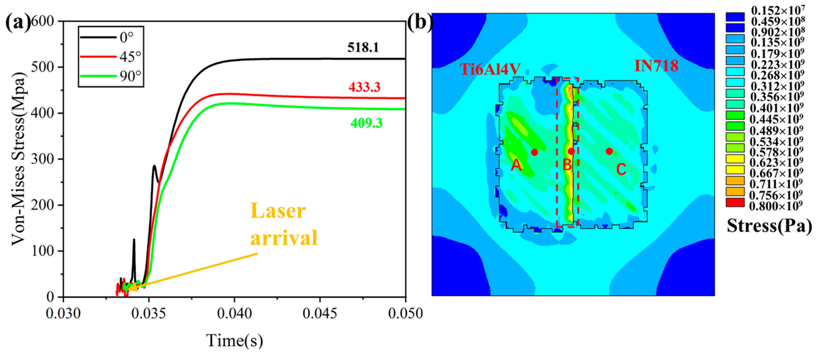
4.2. Effect of Forming Sequence on Thermomechanical Behavior

The forming sequence of different materials also affects the horizontal multi-material structure, so the thermomechanical behavior of Ti6Al4V/IN718 horizontal multi-material is investigated by numerical simulation. In the numerical simulation, Ti6Al4V is formed prior to IN718, in which the scanning strategy is 45° and other process parameters are consistent with the previous ones. The stress cycles at the characteristic points A, B, and C were extracted, as shown in Figure 8a, compared to the IN718/Ti6Al4V structure; at point A, the residual stress of Ti6Al4V is higher, and the stresses only decreased by 11% to as high as 409.5 MPa after the subsequent IN718 scanning. The residual stresses near the interface, i.e., at point B, were 446.8 MPa, compared to the IN718/Ti6Al4V structure, which is about 10% higher. It can be found that under this forming sequence, the high residual stresses are difficult to release due to the high thermal stresses generated by scanning the Ti6Al4V material first and then further increased in the subsequent cooling [32]. The characteristic points exceeded 400 MPa, i.e., high residual stresses on the material surface and near the interface. The residual stress maps of the surface after forming were extracted, as shown in Figure 8b. It can be found that there is a stress concentration along the interface of the material, and the peak residual stress exceeds 700 MPa, which may lead to cracks or even cracks at the interface, which is not conducive to the bonding between the two materials. Moreover, the high residual stresses on the material surface (dark-colored area) are more widely distributed, and the stresses along the scanning line direction on the surface of the IN718 material are also higher than those of the IN718/Ti6Al4V structure. Therefore, the horizontal multi-material structure using IN718/Ti6Al4V forming sequence is more favorable.

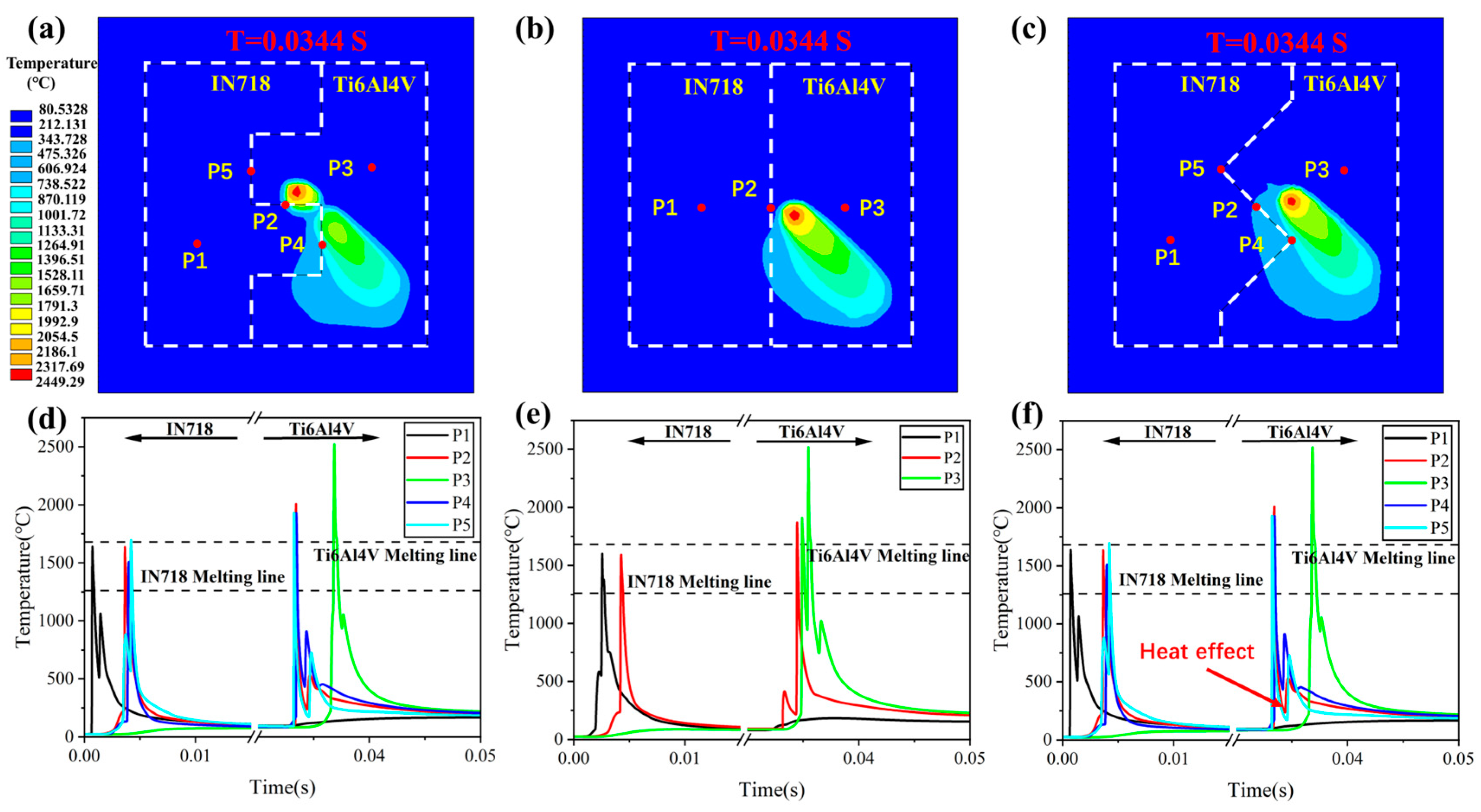
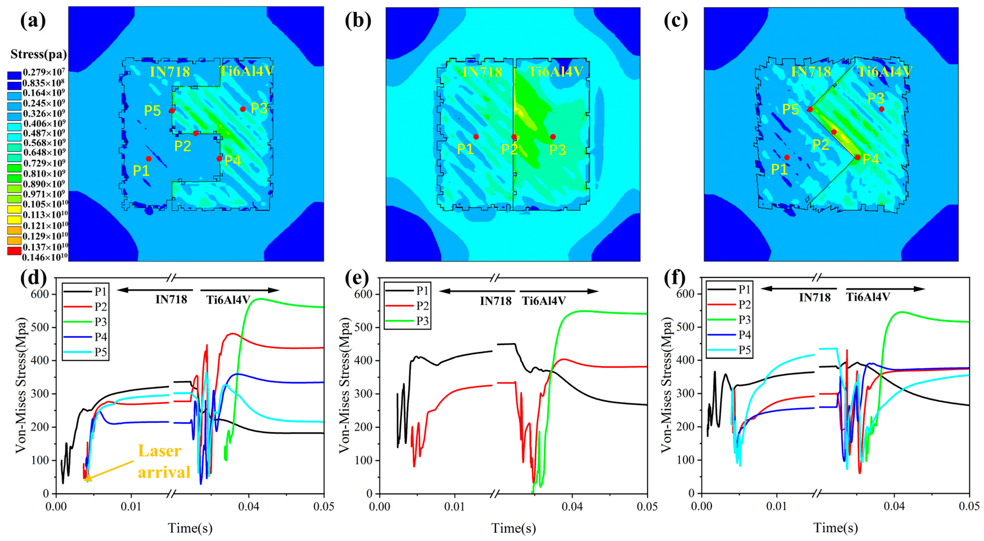
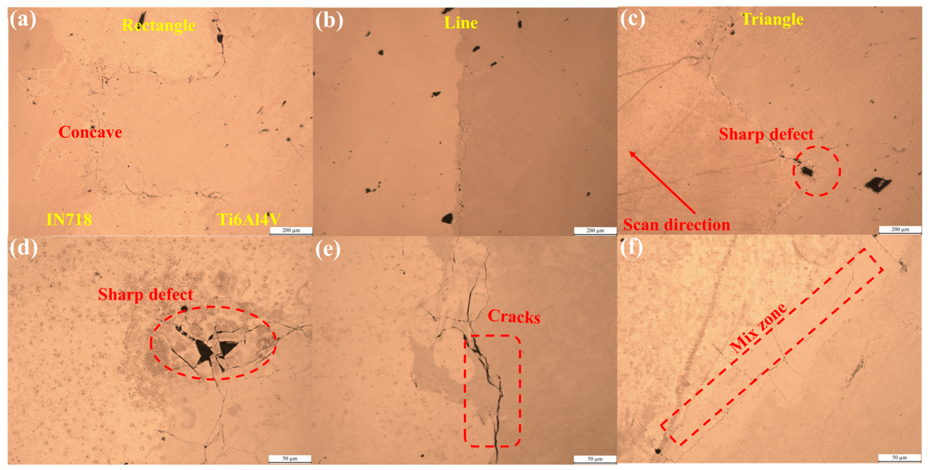
4.3. Effect of Interfacial Structure on Thermomechanical Behavior

Horizontal multi-material structures can define different interfacial shapes compared to a single multi-material interfacial shape in the vertical direction. For example, a wavy or serrated interface may increase the contact area between different materials, thereby increasing the bond strength of the interface and forming a stronger metallurgical bond. Different interface shapes may affect heat flow distribution during the forming process, which in turn affects the thermal stress distribution. Triangular waveform suture interfaces, commonly found in nature, exhibit specific mechanical behavior. Their geometric parameters, such as amplitude, frequency, and hierarchy, can be utilized for non-linear tailoring to enhance mechanical properties [33]. In order to investigate the effect of different interface shapes on the thermomechanical behavior during the forming process, a periodic single wave with a general trapezoidal shape [34] is used in this paper as the interface shape of a horizontal multi-material. As shown in Figure 9a, the single-wave trapezoidal interface can be described by the wavelength λ, the amplitude A, and the interface length g, where the cusp angle of the waveform is θ and β is the shape factor, and the relationship between them satisfies the following equation:
tan θ = λ 2 A
Therefore, it can be found that the general trapezoidal single wave is determined by the above-mentioned parameters, which in turn determines the cusp angle θ, and finally the shape of the general trapezoid is determined according to different shape factors β. As shown in Figure 9b, the single-wave trapezoidal shape is rectangular at β = 0, trapezoidal at 0< β < θ, and triangular at β = θ. In this study, considering the resolution of the finite element model, i.e., the mesh size, the difference between rectangle and trapezoid is not significant, so the rectangle and triangle are used as the shapes of the horizontal multi-material interface for the study.
Numerical simulations of temperature and stress fields are performed for the finite element model with different interface shapes (rectangular, linear, and triangular). For the convenience of the study, the characteristic points of IN718, Ti6Al4V, and the vicinity of the interface in the model are extracted, as shown in Figure 10a–c, and the temperature cycles of the characteristic points under different interface shapes are shown in Figure 10d–f. When scanning the IN718 material, the peak temperature of 1 is mainly affected by the length of the scanning line, which is the highest in the straight-line shape, due to the longer scanning line and more molded area, which makes the temperature accumulate higher. While scanning the Ti6Al4V material. As in the previous study, the higher laser energy and the effect of material properties resulted in the highest peak near Ti6Al4V (P3) at 2500 °C, which would lead to higher residual stresses. By analyzing the temperature cycling of the characteristic points near the interface, it can be found that the points near the interface (P2, P4, and P5) exceed the melting point of the material under two heating cycles, and their peak temperatures reach about 2000 °C when scanning the Ti6Al4V. The two cycles of heating, as well as the higher peak temperatures, lead to higher residual stresses near the interface. In addition, under different interface shapes, the scanning vector’s length and the scanning line’s distance from the interface also affect the temperature cycling. It can be found in Figure 10c,f that the points near the interface are at lower temperatures because they are farther away from the scanning line at this time and are less affected by the thermal influence of the subsequent scanning line. In Figure 10b,e, on the other hand, the points near the interface have higher peak temperatures due to the longer scan lines at this point. They are closer to the feature points near the interface and are more thermally influenced by the other scan lanes, resulting in more significant temperature fluctuations. In the rectangular interface, shown in Figure 10a,d, the remelting temperature near the interface is the highest and longest. The higher peak temperature near the interface and the more considerable thermal influence will result in a higher temperature gradient and cooling rate, which will be unfavorable for the bonding between the two materials.
The numerical simulation results of the extracted stress field are shown in Figure 11a–c for the multi-material residual stress distribution at the IN718/Ti6Al4V under different interface shapes and Figure 11d–f for the stress cycling at the characteristic points. It can be found in both plots that the residual stress (P1) of the IN718 material is affected by the scanning vector length, which is the highest under the linear interface, with the residual stress exceeding 300 MPa. Comparatively speaking, the residual stress is higher in Ti6Al4V material portion, and the high-temperature gradient in the temperature field leads to the peak residual stress at the point 3 close to 550 MPa. For both IN718 and Ti6Al4V materials, the high stress at the interface results in higher residual stress in the region near the interface, as in the previous study. The analysis of the characteristic points near the interface (P2, P4, and P5) shows that the stresses at P2 are elevated during the Ti6Al4V scanning for different interface shapes, with the highest elevation of about 60% in the rectangular shape, which may be due to the direction of the interface shape and the scanning line at this point, and the lowest elevation of about 18% in the triangular interface, where the direction of scanning is parallel to the direction of the interface shape. In the rectangular and triangular interface, the residual stress at P4 is also elevated in the subsequent scans, and the residual stress is also more significant, close to 400 MPa. However, P5 is the opposite, and the residual stress decreases. Moreover, a comparison of the two-point locations reveals that for the two materials, IN718, Ti6Al4V, and, as in our previous study of IN718/CuCrZr [35], located at the tooth valley (P5) is lower than that at the tip (p4), because IN718 better accommodates the stress at the tip of the Ti6Al4V material. In addition, since P4 and P5 are located at the tip under the triangular interface, their residual stresses are higher than those of the rectangular ones. By analyzing the stress field under different interface shapes, it can be obtained that compared with the straight-line interface, the rectangular and triangular interfaces reduce the residual stress near the interface in a particular area, but the stress concentration occurs at certain sharp corners. The residual stresses in the straight line interface are concentrated near the interface, and if the force perpendicular to the interface is applied, the material separation at the interface may quickly occur, which makes the multi-material performance decrease, and by changing the shape of the interface, the distribution of the residual stresses at the interface can be changed, which is conducive to the reduction of the concentration of the stresses near the interface.

5. Experimental Results

5.1. Experimental Process

The IN718/Ti6Al4V and Ti6Al4V/IN718 horizontal multi-materials with different scanning strategies as described above, as well as the IN718/Ti6Al4V horizontal multi-material with different interfacial shapes in the 45° scanning strategy, are experimentally shaped accordingly. The laser scanning parameters in the experiments are kept consistent with those in the numerical simulations. The size of the sample model is 8 × 8 × 0.5 mm3. In order to facilitate the separation of the sample from the substrate, a base of 8 × 8 × 2 mm3 is first formed on the substrate, on which the horizontal multi-material is subsequently formed. Using a laboratory DiMetal-100H machine (laseradd, Zhuhai, China), the powder lay-up carriage was fed into the improvement for horizontal multi-material forming, as shown in Figure 12a. The specific forming steps are shown in Figure 12b. With the powder drop device and the powder suction tube, three powder spreading and two powder suction are required to form one layer of horizontal multi-material. The cycle of multi-layer printing is carried out so that all the horizontal multi-material prototypes can be printed in one experiment. Figure 12c–e shows the photographs of the upper surface of the forming cylinder during the forming process, and Figure 12f shows the final printed samples, in which rows 1 and 2 show the IN718/Ti6Al4V horizontal multi-material samples, rows 3 and 4 show the Ti6Al4V/IN718 horizontal multi-material samples, and rows 5 and 6 show the IN718/Ti6Al4V horizontal multi-material samples with different interface shapes.

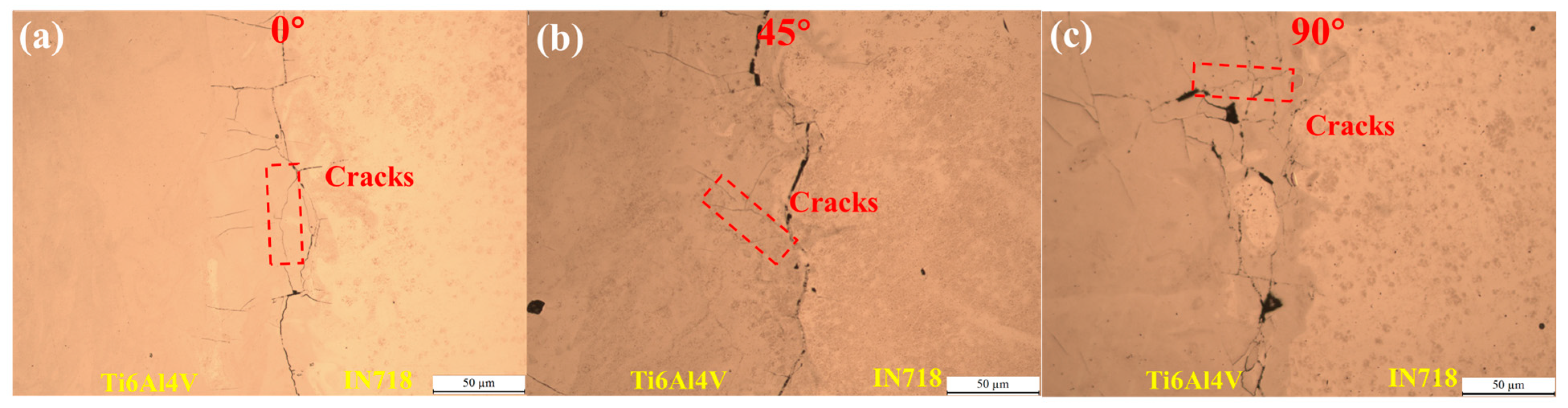
5.2. Analysis of Experimental Results

Experimental printing of the IN718/Ti6Al4V horizontal multi-material structure under different scanning strategies, super depth of field observation near the interface of the sample as well as metallographic observation after polishing, resulted in the pictures shown in Figure 13. Figure 13a–c shows the ultra-depth-of-field pictures of the sample surface, and macroscopically, no cracking occurs between the two materials. It can be found that the interface bulge is most profound under the 0° scanning strategy. The scanning line is parallel to the interface, and then the interface material undergoes thermal expansion along the scanning line to both sides, which squeezes the interface. In addition, from the temperature field, it can be found that the longer scanning line at 0° results in a higher peak temperature of the molten pool, and the concentration of heat input causes the material at the interface to undergo a more significant thermal expansion, which also leads to spheroidization of the surface of the samples. Since the peak temperature of the molten pool is higher, the tension on the surface of the material will increase significantly. This surface tension causes the surface of the material to become spherical in order to minimize the surface energy. Thus, the quality of the surfaces is poorer with this scanning strategy. The interfacial bulge is reduced in the 45° and 90° strategies and the surface quality is improved. Figure 13d–f shows the metallographs of the samples near the interface, where strong convection occurs inside the melt pool, and the mixing of materials occurs during the scanning process due to the combination of the Marangoni effect [36] and surface tension. Compared to the vertical multi-material structure, the material mixing zone is not apparent at this point, especially in the 0° sweep strategy; the material interface segmentation is pronounced, while it can be observed partially in the 45° and the 90° strategy. It indicates that the scanning strategy also affects the material mixing near the interface, and mixing the materials when they are parallel to the interface is challenging. In order to evaluate defects more systematically, we define the classification of crack length for ≤50 μm as a short crack, >50 μm and <100 μm as a medium crack, for ≥100 μm as a long crack. Some cracks are present at both interfaces, and the cracks are also towards the Ti6Al4V material side, similar to those in the numerical simulations of the stress field, where the cracks extend in the direction of the high residual stresses. In the 90° strategy, the longest cracks were observed to exceed 50 μm, at which time the main cracks were medium, and the cracks spread, resulting in apparent cracks at the interface. Since the melt pool is orientated perpendicular to the interface, the contraction force pulls on the interface after the melt pool cools down, causing the cracks to extend along the interface. Under the 45° strategy, due to the appearance of some unfused holes, small cracks spread from the interface to the hole, reaching 100 μm, but the overall interface was well combined with no apparent defects. In the 0° scanning strategy, the crack length of the Ti6Al4V side along the scanning direction exceeded 100 μm, and a small degree of cracking occurred at the interface. There are mainly small cracks and a few long cracks. In summary, the horizontal multi-material samples analyzed under different scanning strategies show that different scanning strategies have an effect on the surface quality, interface bonding, and defects of the samples, and the results correspond to those in the numerical simulation, where the scanning strategy directly influences the action of the laser on the material.
The metallographs near the interface of the Ti6Al4V/IN718 structure under different scanning strategies are shown in Figure 14. Compared with the IN718/Ti6Al4V structure, the interfaces are cracked to different degrees at this time, and the cracks occur near the Ti6Al4V material side, which is the same as the stress concentration area in the numerical simulation. Moreover, the strategy is most severe at 90° scanning with the most profound crack extension. Similar to the vertical multi-materials, it can be found from the numerical simulation that forming Ti6Al4V first leads to the generation of higher residual stress (460 MPa), which makes it challenging to release the residual stress (409.5 MPa) during the subsequent forming of IN718. Moreover, the two materials are directly prone to brittle phases, which leads to crack formation and further expansion under residual stress. In addition, it can be found that the crack length near the interface is more than the IN718/Ti6Al4V structure, and the crack is more than 100 μm, that is, all are long cracks. Therefore, forming the Ti6Al4V material first is not favorable to the direct combination of the two materials, resulting in lower overall properties of the formed parts.
Experimental forming of IN718/Ti6Al4V horizontal multi-material with different interfacial shapes, in which a 45° scanning strategy was used, is shown in Figure 15, along with the surface super depth-of-field morphology and the 3D images. It can be noticed in the figure that the interfaces of all three shapes have a certain amount of bumps, which are in the range of 100–200 μm in height. With the significance of the previous study, when the scanning line is parallel to the interface, the bulge of the interface will be more serious; for example, as shown in Figure 15c,f, the bulge of the interface in the triangular interface which is parallel to the scanning line is higher. From the temperature field in the numerical simulation, it can be found that when scanning Ti6Al4V, the melt pool’s peak temperature is high, making some spheroidization on the Ti6Al4V material side. Moreover, the bumps are also higher inside the rectangular and triangular shapes of the interface shape due to the more severe heat accumulation during laser scanning at the sharp corners. In the figure, it can be found that the height of the lower left part of the sample is also higher, which may be due to the influence of the wind field when the scanning line is scanning from the lower left to the upper right, which makes part of the spatter blowing downward to stay on the sample. Different interfaces lead to different convex behavior on the interface.
The IN718/Ti6Al4V multi-material under different interface shapes are subjected to metallographic observation near the interface, as shown in Figure 16, where the material on the left is IN718 and the right is Ti6Al4V. A more precise outline can be seen in the figure, and it is found that cracks are generated near the interface under different interface shapes and extended along the interface, mainly medium cracks. The defects are most prevalent in rectangular-shaped structures. In the rectangular shape, the laser scans back and forth at right angles, which tends to produce a large temperature gradient; as in the previous temperature numerical simulation, the temperature fluctuation at the characteristic points near the interface is more significant, and thus, more cracks are produced. In the stress field, the residual stress is lower in the rectangular concave surface, yielding fewer defects and no cracking at that location. In the rectilinear shape, the cracks started from the mixing zone of the material until they extended along the interface, leading to cracking on the Ti6Al4V material side. In the triangular shapes, there are fewer interfacial cracks in the direction parallel to the scanning direction. In contrast, the shape perpendicular to the scanning direction has vertical cracks, as shown in Figure 16f. It significantly influences the Marangoni effect of the molten pool and the surface tension in this direction, which produces a broader material mixing zone, which is in line with the pattern seen in the previous samples of the scanning strategy. In addition, near the rectangular and triangular sharp corners, the cracking is more severe, and hole defects are present. From the numerical simulations, it can also be found that the abrupt change in geometry at the sharp corners of the interface leads to stress concentration, which becomes a preferred location for crack initiation and extension. At the sharp corners, the formation and flow of the melt pool may be affected, resulting in hole defects. In summary, the different shapes of the interface make different printing characteristics in the forming process, which makes the different effects of laser scanning, and the laser scanning will change the local energy input and heat distribution, resulting in the shape of the interface affecting the defect formation and distribution.

6. Conclusions

In this study, the thermomechanical behavior of the IN718/Ti6Al4V horizontal multi-material structure under scanning strategy is simulated and analyzed by establishing a horizontal multi-material finite element model. Numerical simulations of the Ti6Al4V/IN718 structure were also carried out to investigate the effects of the scanning strategy and the forming sequence on the temperature distribution, thermal cycling behavior, and stress field at the interface between the materials. Then, based on the above simulation results and relevant theoretical analyses, different interface shapes were designed to investigate further the influence of interface shape on the thermomechanical behavior of IN718/Ti6Al4V horizontal multi-material. Finally, the IN718/Ti6Al4V horizontal multi-material structure was shaped experimentally, and the metallurgical bonding and defects at the interface were analyzed by super depth-of-field microscope and metallurgical microscope to observe the surface morphology of the samples, as well as the microscopic morphology and the distribution of defects at the interface. The main conclusions are as follows:
The scanning strategy has a significant impact on the thermomechanical behavior near the horizontal IN718/Ti6Al4V interface, and the scanning strategy at 45° helps to distribute the energy more uniformly and reduces the local overheating and residual stress concentration, thus reducing the risk of crack and defect formation.
The horizontal multi-material forming order also affects the interface bonding by numerically simulating IN718/Ti6Al4V horizontal multi-material under different forming orders. The results show that forming Ti6Al4V first leads to higher residual stresses at the interface and is difficult to release in subsequent printing, which is not favorable for direct material bonding. Therefore, the IN718/Ti6Al4V structure is more favorable.
The influence of the interface shape on the thermal behavior near the interface of IN718/Ti6Al4V horizontal multi-material was explored. Numerical simulations and experimental samples were analyzed to show that the interface shape not only affects the crack formation and extension paths leading to cracking at the interface, but additionally, in rectangular and triangular shapes, the vicinity of the sharp corners leads to severe cracking and pore defects.
In LPBF forming horizontal heterogeneous materials, we can avoid a too-large angle between scan line and interface by selecting a suitable scanning strategy. In addition, sharp corners and mutations are avoided through good interface shape design. For example, using rounded corners or streamlined designs can reduce stress concentration and improve the bonding strength of the interface.

Author Contributions

Conceptualization, Y.H. and L.L.; methodology, T.W. and L.L.; software, Y.L. and Y.H.; validation, T.W. and Y.L.; formal analysis, T.W. and C.H.; investigation, C.H. and H.T.; resources, D.W. and Y.Y.; data curation, Y.H. and W.Z.; writing—original draft preparation, T.W. and D.W.; writing—review and editing, H.T., Y.Y. and W.Z.; visualization, C.H., Y.L. and L.L.; supervision, Y.Y. and H.T.; project administration, W.Z. and D.W.; funding acquisition, D.W. and H.T. All authors have read and agreed to the published version of the manuscript.

Funding

This article is supported by the following projects: National Key Research and Development Program of China (No. 2022YFB4600303), National Natural Science Foundation of China (No. 52073105), Guangdong Basic and Applied Basic Research Foundation (Nos. 2022B1515020064, 2022B1515120025).

Data Availability Statement

The raw data supporting the conclusions of this article will be made available by the authors on request.

Conflicts of Interest

The authors declare no conflict of interest.

References

  1. Sam, M.; Jojith, R.; Radhika, N. Progression in Manufacturing of Functionally Graded Materials and Impact of Thermal Treatment—A Critical Review. J. Manuf. Process. 2021, 68, 1339–1377. [Google Scholar] [CrossRef]
  2. Wang, D.; Liu, L.; Deng, G.; Deng, C.; Bai, Y.; Yang, Y.; Wu, W.; Chen, J.; Liu, Y.; Wang, Y.; et al. Recent Progress on Additive Manufacturing of Multi-Material Structures with Laser Powder Bed Fusion. Virtual Phys. Prototyp. 2022, 17, 329–365. [Google Scholar] [CrossRef]
  3. Wei, C.; Li, L. Recent Progress and Scientific Challenges in Multi-Material Additive Manufacturing via Laser-Based Powder Bed Fusion. Virtual Phys. Prototyp. 2021, 16, 347–371. [Google Scholar] [CrossRef]
  4. Ansari, M.; Jabari, E.; Toyserkani, E. Opportunities and Challenges in Additive Manufacturing of Functionally Graded Metallic Materials via Powder-Fed Laser Directed Energy Deposition: A Review. J. Mater. Process. Technol. 2021, 294, 117117. [Google Scholar] [CrossRef]
  5. Hosseini, E.; Popovich, V.A. A Review of Mechanical Properties of Additively Manufactured Inconel 718. Addit. Manuf. 2019, 30, 100877. [Google Scholar] [CrossRef]
  6. Karim, A.N.M.; Ikram, M.; Emrul Kays, H.M.; Abdesselam, M.; Ginta, T.L. Assessment of Machining Cost for End-Milling of Ti-6Al-4V Titanium Alloy through RSM-Based Parametric Model. Adv. Mater. Res. 2014, 903, 83–89. [Google Scholar] [CrossRef]
  7. Jin, B.; Wang, Q.; Zhao, L.; Pan, A.; Ding, X.; Gao, W.; Song, Y.; Zhang, X. A Review of Additive Manufacturing Techniques and Post-Processing for High-Temperature Titanium Alloys. Metals 2023, 13, 1327. [Google Scholar] [CrossRef]
  8. Soni, N.; Renna, G.; Leo, P. Advancements in Metal Processing Additive Technologies: Selective Laser Melting (SLM). Metals 2024, 14, 1081. [Google Scholar] [CrossRef]
  9. Razavykia, A.; Brusa, E.; Delprete, C.; Yavari, R. An Overview of Additive Manufacturing Technologies—A Review to Technical Synthesis in Numerical Study of Selective Laser Melting. Materials 2020, 13, 3895. [Google Scholar] [CrossRef]
  10. Yang, Y.; Jiang, R.; Han, C.; Chen, J.; Li, H.; Wang, Y.; Tang, J.; Zhou, H.; Hu, W.; Zheng, B.; et al. Frontiers in Laser Additive Manufacturing Technology. Addit. Manuf. Front. 2024, 3, 200160. [Google Scholar] [CrossRef]
  11. Zhang, C.; Chen, F.; Huang, Z.; Jia, M.; Chen, G.; Ye, Y.; Lin, Y.; Liu, W.; Chen, B.; Shen, Q.; et al. Additive Manufacturing of Functionally Graded Materials: A Review. Mater. Sci. Eng. A 2019, 764, 138209. [Google Scholar] [CrossRef]
  12. Xie, D.; Lv, F.; Yang, Y.; Shen, L.; Tian, Z.; Shuai, C.; Chen, B.; Zhao, J. A Review on Distortion and Residual Stress in Additive Manufacturing. Chin. J. Mech. Eng. Addit. Manuf. Front. 2022, 1, 100039. [Google Scholar] [CrossRef]
  13. Shah, K.; Haq, I.U.; Shah, S.A.; Khan, F.U.; Khan, M.T.; Khan, S. Experimental Study of Direct Laser Deposition of Ti-6Al-4V and Inconel 718 by Using Pulsed Parameters. Sci. World J. 2014, 2014, 841549. [Google Scholar] [CrossRef]
  14. Willy, H.J.; Li, X.; Tan, Y.H.; Chen, Z.; Cagirici, M.; Borayek, R.; Herng, T.S.; Ong, C.Y.A.; Li, C.; Ding, J. Overview of Finite Elements Simulation of Temperature Profile to Estimate Properties of Materials 3D-Printed by Laser Powder-Bed Fusion. Chin. Phys. B 2020, 29, 48101. [Google Scholar] [CrossRef]
  15. Chen, C.; Gu, D.; Dai, D.; Du, L.; Wang, R.; Ma, C.; Xia, M. Laser Additive Manufacturing of Layered TiB2/Ti6Al4V Multi-Material Parts: Understanding Thermal Behavior Evolution. Opt. Laser Technol. 2019, 119, 105666. [Google Scholar] [CrossRef]
  16. Huang, G.; Lin, K.; Gu, D.; Wang, R.; Liu, H.; Shi, K. The Influence of Building Parameters on Residual Stress, Interfacial Structure, and Cracking Control of Laser Powder Bed Fusion Processed Ti6Al4V/AlMgScZr Multi-Material Parts. J. Mater. Process. Technol. 2024, 330, 118479. [Google Scholar] [CrossRef]
  17. Mao, S.; Yang, B.; Liu, G.; Liu, G.; Zhang, Z. Temperature Distribution and Residual Stress Evolution at the Interface of CuCrZr/316 L Multi-Material by Laser Powder Bed Fusion. Opt. Laser Technol. 2023, 163, 109355. [Google Scholar] [CrossRef]
  18. Roberts, I.A.; Wang, C.J.; Esterlein, R.; Stanford, M.; Mynors, D.J. A Three-Dimensional Finite Element Analysis of the Temperature Field during Laser Melting of Metal Powders in Additive Layer Manufacturing. Int. J. Mach. Tools Manuf. 2009, 49, 916–923. [Google Scholar] [CrossRef]
  19. Wang, X.; Liu, M.; Li, Z.; Yao, B.; Wang, B.; Wang, N. Finite Element Simulation and Experimental Study of Selective Laser Melted 40Cr Steel Forming Process. Opt. Laser Technol. 2024, 169, 110080. [Google Scholar] [CrossRef]
  20. Roy, S.; Juha, M.; Shephard, M.S.; Maniatty, A.M. Heat Transfer Model and Finite Element Formulation for Simulation of Selective Laser Melting. Comput. Mech. 2018, 62, 273–284. [Google Scholar] [CrossRef]
  21. Luo, C.; Qiu, J.; Yan, Y.; Yang, J.; Uher, C.; Tang, X. Finite Element Analysis of Temperature and Stress Fields during the Selective Laser Melting Process of Thermoelectric SnTe. J. Mater. Process. Technol. 2018, 261, 74–85. [Google Scholar] [CrossRef]
  22. Mishra, A.K.; Aggarwal, A.; Kumar, A.; Sinha, N. Identification of a Suitable Volumetric Heat Source for Modelling of Selective Laser Melting of Ti6Al4V Powder Using Numerical and Experimental Validation Approach. Int. J. Adv. Manuf. Technol. 2018, 99, 2257–2270. [Google Scholar] [CrossRef]
  23. Hussein, A.; Hao, L.; Yan, C.; Everson, R. Finite Element Simulation of the Temperature and Stress Fields in Single Layers Built Without-Support in Selective Laser Melting. Mater. Des. 2013, 52, 638–647. [Google Scholar] [CrossRef]
  24. Zhang, H.; Xu, W.; Xu, Y.; Lu, Z.; Li, D. The Thermal-Mechanical Behavior of WTaMoNb High-Entropy Alloy via Selective Laser Melting (SLM): Experiment and Simulation. Int. J. Adv. Manuf. Technol. 2018, 96, 461–474. [Google Scholar] [CrossRef]
  25. Zhang, Y.; Guillemot, G.; Bernacki, M.; Bellet, M. Macroscopic Thermal Finite Element Modeling of Additive Metal Manufacturing by Selective Laser Melting Process. Comput. Methods Appl. Mech. Eng. 2018, 331, 514–535. [Google Scholar] [CrossRef]
  26. Zhang, D.; Zhang, P.; Liu, Z.; Feng, Z.; Wang, C.; Guo, Y. Thermofluid Field of Molten Pool and Its Effects during Selective Laser Melting (SLM) of Inconel 718 Alloy. Addit. Manuf. 2018, 21, 567–578. [Google Scholar] [CrossRef]
  27. Gao, S.; Tan, Z.; Lan, L.; Lu, G.; He, B. Experimental Investigation and Numerical Simulation of Residual Stress and Distortion of Ti6Al4V Components Manufactured Using Selective Laser Melting. J. Mater. Eng. Perform. 2022, 31, 8113–8123. [Google Scholar] [CrossRef]
  28. Kubra Karayagiz Alaa Elwany, G.T.B.F.L.J.J.M.I.K.; Arróyave, R. Numerical and Experimental Analysis of Heat Distribution in the Laser Powder Bed Fusion of Ti-6Al-4V. IISE Trans. 2019, 51, 136–152. [Google Scholar] [CrossRef]
  29. Nigito, E.; Diemer, F.; Husson, S.; Ou, S.F.; Tsai, M.H.; Rézaï-Aria, F. Microstructure of NiTi superelastic alloy manufactured by selective laser melting. Mater. Lett. 2022, 324, 132665. [Google Scholar] [CrossRef]
  30. Liu, Y.; Yang, Y.; Wang, D. A Study on the Residual Stress during Selective Laser Melting (SLM) of Metallic Powder. Int. J. Adv. Manuf. Technol. 2016, 87, 647–656. [Google Scholar] [CrossRef]
  31. Yadroitsava, I.; Grewar, S.; Hattingh, D.; Yadroitsev, I. Residual Stress in SLM Ti6Al4V Alloy Specimens. In Proceedings of the Materials Science Forum, Graz, Austria, 10–14 May 2015; Volume 828, pp. 305–310. [Google Scholar]
  32. Liu, B.; Li, B.-Q.; Li, Z.; Bai, P.; Wang, Y.; Kuai, Z. Numerical Investigation on Heat Transfer of Multi-Laser Processing during Selective Laser Melting of AlSi10Mg. Results Phys. 2019, 12, 454–459. [Google Scholar] [CrossRef]
  33. Dunlop, J.W.C.; Weinkamer, R.; Fratzl, P. Artful Interfaces within Biological Materials. Mater. Today 2011, 14, 70–78. [Google Scholar] [CrossRef]
  34. Li, Y.; Ortiz, C.; Boyce, M.C. A Generalized Mechanical Model for Suture Interfaces of Arbitrary Geometry. J. Mech. Phys. Solids 2013, 61, 1144–1167. [Google Scholar] [CrossRef]
  35. Liu, L.; Wang, D.; Wang, T.; Han, C.; Li, Y.; Tan, H.; Zhou, W.; Yan, X.; Lei, L.; Yang, Y. Laser Additive Manufacturing of Multimaterials with Hierarchical Interlocking Interface via a Flexible Scraper-Based Method. Int. J. Mach. Tools Manuf. 2025, 205, 104236. [Google Scholar] [CrossRef]
  36. Zou, F.; Yao, S.; Dong, Y.; Zheng, X.; Xie, M.; Yang, L.; Wang, D. Research on Multiscale Numerical Simulation Method for SLM Melting Process. Metals 2024, 14, 825. [Google Scholar] [CrossRef]
Figure 1. (a) IN718/Ti6Al4V structure finite element model; (b) Rectangular interface IN718/Ti6Al4V structure finite element model.
Metals 15 00454 g001
Figure 2. Thermophysical and mechanical properties of materials: (a) density; (b) thermal conductivity; (c) specific heat capacity; (d) modulus of elasticity; (e) coefficient of thermal expansion; (f) Poisson’s ratio.
Metals 15 00454 g002
Figure 3. SEM morphology of different powders: (a) IN718 powder; (b) Ti6Al4V powder; (c) Schematic diagram of multi-material LPBF forming principle.
Metals 15 00454 g003
Figure 4. (a) Schematic of feature points; (b) 0° scanning strategy; (c) 45° scanning strategy; (d) 90° scanning strategy.
Metals 15 00454 g004
Figure 5. Temperature cycling diagram: (a) Characteristic point; (b) Characteristic point B; (c) Characteristic point C; Stress cycling diagram: (d) Characteristic point A; (e) Characteristic point B; (f) Characteristic point C.
Metals 15 00454 g005
Figure 6. X-direction stress: (a) 0° scan strategy; (b) 45° scan strategy; (c) 90° scan strategy; Y-direction stress: (d) 0° scan strategy; (e) 45° scan strategy; (f) 90° scan strategy.
Metals 15 00454 g006
Figure 7. (a) Residual stress cloud for 0° scanning strategy; (b) Residual stress cloud for 45° scanning strategy; (c) Residual stress cloud for 90° scanning strategy; (d) IN718 residual stress distribution; (e) Surface residual stress distribution.
Metals 15 00454 g007
Figure 8. (a) Stress cycle at characteristic points of Ti6Al4V/IN718 structure; (b) Residual stress cloud of Ti6Al4V/IN718 structure.
Metals 15 00454 g008
Figure 9. (a) Schematic of the general trapezoidal interface geometry with the same parameters; (b) Schematic of the interface shape with different shape factors β.
Metals 15 00454 g009
Figure 10. Schematic diagram of feature points of the finite element model: (a) rectangular interface; (b) linear interface; (c) triangular interface; Temperature cycle diagram of feature points: (d) rectangular interface; (e) linear interface; (f) triangular interface.
Metals 15 00454 g010
Figure 11. Residual stress distribution diagrams: (a) rectangular interface; (b) linear interface; (c) triangular interface; Characteristic point stress cycle diagrams: (d) rectangular interface; (e) linear interface; (f) triangular interface.
Metals 15 00454 g011
Figure 12. (a) Improved powder spreading car; (b) Flow chart of forming experiment; Experimental process diagram: (c) Scanned Ti6Al4V material; (d) Powder suction completed; (e) Scanned IN718 material; (f) Final samples.
Metals 15 00454 g012
Figure 13. (ac) Superfields near the IN718/Ti6Al4V structural interface under different scanning strategies; (df) metallographs near the IN718/Ti6Al4V structural interface under different scanning strategies.
Metals 15 00454 g013
Figure 14. Metallographic images near the interface of Ti6Al4V/IN718 structure under different scanning strategies: (a) 0°; (b) 45°; (c) 90°.
Metals 15 00454 g014
Figure 15. (ac) Surface topography with different interface shapes; (df) 3D view of the surface topography.
Metals 15 00454 g015
Figure 16. Metallography near the IN718/Ti6Al4V multi-material interface with different interface shapes: (a,d) Rectangle; (b,e) Line; (c,f) Triangle.
Metals 15 00454 g016
Table 1. Numerical simulation of LPBF powder property parameters and laser parameters.
ParametricIN718Ti6Al4V
Absorption rate0.3 [26]0.4 [27]
Porosity0.50.5
Thermal conductivity (W/m·°C)100100
Melting point (°C)12601680
Scanning speed (mm/s)900900
Laser power (W)160190
Layer thickness (μm)30
Scanning pitch (μm)80
Spot diameter (μm)80
Disclaimer/Publisher’s Note: The statements, opinions and data contained in all publications are solely those of the individual author(s) and contributor(s) and not of MDPI and/or the editor(s). MDPI and/or the editor(s) disclaim responsibility for any injury to people or property resulting from any ideas, methods, instructions or products referred to in the content.

