Article

Effects of Annealing on Carbide Size Distribution and Mechanical Properties of 1.0C-1.5Cr Bearing Steel Prepared by Continuous Casting with 510 mm × 390 mm × 250 mm Dimensions

1
College of Materials Science and Technology, Nanjing University of Aeronautics and Astronautics, Nanjing 210016, China
2
Key Laboratory of Materials Preparation and Protection for Harsh Environment, Ministry of Industry and Information Technology, Nanjing 210016, China
*
Author to whom correspondence should be addressed.
Metals 2025, 15(4), 467; https://doi.org/10.3390/met15040467
Submission received: 5 December 2024 / Revised: 14 February 2025 / Accepted: 18 February 2025 / Published: 21 April 2025

Abstract

:
As the cross-sectional size of bearing steel increases, maintaining a uniform microstructure becomes more difficult. To address this issue in large-section 1.0C-1.5Cr bearing steel, the behavior of carbides during isothermal spheroidization annealing at different positions within the steel was investigated. Quantitative metallography was used to measure the mean diameter of carbides (D), the number of carbides per area (n), and the carbide particle size distribution at both the 1/2 position and the center position of the steel. The results of the study showed good spheroidization of carbides in all the specimens except for the presence of lamellar pearlite organization in the specimens with austenitizing temperatures of 760 °C and 880 °C. As the austenitizing and second annealing temperatures and times increased, the mean diameter of carbides (D) became larger, while the number of carbides per area (n) decreased. It is worth noting that the carbides in the center position are smaller than in the 1/2 position, although the center position had a higher density of carbides. Based on the measured values of D and n, a model was developed to describe the relationship between them. In addition, the mechanical properties were influenced by this uneven carbide distribution: as the carbide size increased, tensile strength decreased, while elongation followed a similar trend. Additionally, tensile strength was higher at the center position than at the 1/2 position, whereas elongation was greater at the 1/2 position.

1. Introduction

In recent years, the demand for large-section bearing steel has increased significantly, driven by advancements in the manufacturing industry and the growing requirements of high-end equipment such as wind power systems and rail transportation. This trend emphasizes the need for high-quality materials capable of meeting large-scale production demands [1,2]. However, as the size of the bearing sections increases, issues often arise, including uneven distribution of carbides [3], suboptimal carbides morphology [4] and uneven tissue distribution [5]. These challenges, influenced by the genetic characteristics of the material, can severely affect the performance and fatigue life of large-section bearing steel [6].
For eutectic and hypereutectic steels, spheroidization annealing is a crucial heat treatment process that improves the morphology and distribution of carbides. It plays a key role in softening the microstructure prior to cold deformation [7,8,9]. During spheroidization, lamellar carbides transform into spheroidal carbides, which become uniformly distributed within the ferrite matrix. This structural change reduces the material’s strength and hardness while significantly improving its plasticity and toughness compared to the original lamellar structure [10]. Therefore, understanding the effects of spheroidization annealing on the microstructure and mechanical properties of these steels is essential.
The isothermal spheroidization annealing process aims to achieve homogeneous and stable spheroidal carbides based on the principle of critical annealing. Initially, the steel is heated to the austenitizing temperature and held for an extended period to ensure a sufficient amount of undissolved carbides, which act as a core for non-uniform nucleation. Following this, the steel is cooled below the eutectic temperature and maintained at that lower temperature for an extended duration before being slowly cooled to even lower temperatures and then air-cooled. Research by Ankit [11] and Verhoeven [12] identifies two transformation modes of supercooled austenite below the A1 line: the pearlite transformation, where cementite and ferrite form lamellar pearlite, and the divorced eutectoid transformation (DET), where excess carbon precipitates from the matrix, nucleates, and grows on undissolved carbides, leading to coarse spheroidal carbides. To achieve desirable mechanical properties that meet machinability standards, it is crucial to avoid the pearlite transformation, ensuring the formation of carbides that enhance the material’s overall performance.
Large-section bearing steel often experiences issues such as tissue and chemical composition inhomogeneity across different regions of the cross-section, stemming from variations in solidification rates and the redistribution of solute elements during production. The spheroidization process of pearlite steel is intricately linked to its initial microstructure and chemical makeup [13]. For instance, Hwang et al. [8] investigated how the initial microstructure of SAE 52100 steel affects spheroidization, revealing that martensitic and bainitic structures spheroidize more rapidly than the pearlite structures. Similarly, Li et al. [14] examined the impact of pearlite lamella spacing and cluster size on the spheroidization and annealing processes, demonstrating that finer spacing and smaller clusters significantly enhance spheroidization. Additionally, Zhang et al. [15] found that the addition of manganese or chromium slows down the spheroidization and dissolution of lamellar cementite, while the effect of silicon is less pronounced. Conversely, Kim et al. [16] reported that increasing silicon content can impede cementite spheroidization in high-carbon chromium steels. Lee et al. [17] further explored the influence of carbide distribution on fracture toughness in SA 508 steel, emphasizing the importance of avoiding large carbides and favoring fine, evenly distributed carbides to enhance toughness. Those findings underscore that both microstructural and compositional heterogeneities critically influence the spheroidization annealing process, ultimately determining the material’s performance and longevity.
Existing research on the spheroidization annealing process of eutectic steel primarily focuses on small-sized specimens, leaving a gap in the understanding of microstructure evolution in large-section bearing steel across various regions during this process. Consequently, investigating the carbide evolution at different areas of large-section bearing steel during spheroidization annealing is crucial for optimizing heat treatment procedures and enhancing end-use properties. In this work, the influence of spheroidal annealing parameters on the spheroidizing effect at different regions of 1.0C-1.5Cr large-section bearing steel was systematically investigated with the aim of elucidating the carbide evolution behavior in these regions. The mean diameter of carbides (D), the number of carbides per area (n), and the carbide particle size distribution were measured, and the relationship between D and n was further discussed, and a model describing the relationship between them was developed. In addition, the effect of carbide size on tensile strength and elongation is discussed, providing the necessary insights for obtaining optimal mechanical properties that meet machining standards.

2. Materials and Methods

2.1. Materials Preparation

The steel sample utilized in this study is a large-section continuous casting billet composed of 1.0C-1.5Cr, measuring 510 mm in length, 390 mm in width, and 250 mm in height as shown in Figure 1a. The region between 3/4 and 1/2 from the heart is referred to as the 1/2 position and noted as region A. The region within 1/4 from the heart is referred to as the center position and noted as region B, as shown in Figure 1b. Following the sampling process, the specimens underwent a high-temperature homogenization treatment at 1200 °C for 3 h. After treatment, the specimens were processed using a two-roll mill, where they were subjected to multi-pass rolling, achieving a total deformation of 70% with a final rolling temperature of 820 °C. This process resulted in a pearlite microstructure, as illustrated in Figure 1e,f. The chemical compositions of regions A and B were analyzed using an ICP spectrometer (ICP, Optima 8X00, Waltham, MA, USA), with results summarized in Table 1. The reason for the compositional differences is mainly due to the fact that there is a significant thermal gradient from the surface to the center as the section size increases, resulting in a non-uniform solidification process. The 1/2 position solidifies earlier than the center position, resulting in segregation of alloying elements. In addition, the carbon content in the center position (1.02 wt.% C) tends to be higher than in the 1/2 position (0.99 wt.% C) due to the enrichment of solute elements in the final stages of solidification. The spacing of the pearlite lamellae in regions A and B was determined to be 0.12 μm and 0.10 μm, respectively, using the circular truncation method [18], as outlined in Equation (1).
σ = π d M x ,
where d is the diameter of the circle drawn, M is the magnification of the micrograph, and x is the number of intersections of the lamellae carbide with the measured circle. The reason for this is mainly due to the fact that the center position contains more C elements than the 1/2 position; the higher the carbon content, the more lamellar cementite is formed during supercooling austenite decomposition, and the smaller the lamellae spacing is.
For hypereutectoid steels, isothermal spheroidization annealing is essential for achieving a uniform and stable spheroidized microstructure [19,20]. In this study, spheroidization annealing was performed in a tube furnace (TL1700, Telstra, Tianjin, China) under a protective atmosphere of 99.99% high-purity argon. The spheroidization process is illustrated in Figure 1d, and the specific parameters for the annealing are detailed in Table 2. We have systematically investigated the effects of various factors, including austenitizing temperature, austenitizing time, secondary annealing temperature, and secondary annealing time, on the mean diameter of carbides (D), the number of carbides per area (n), and carbide particle size distribution at different locations within the large-section bearing steel. Notably, after completing the secondary annealing stage, the material was cooled to 650 °C at a controlled rate of 30 °C/h before being subjected to air cooling.

2.2. Microstructural Characterization

After the completion of spheroidization annealing, the specimens were sectioned into samples measuring 10 mm × 10 mm × 5 mm. These samples were then ground and polished according to established standards and etched with a 4% nitric acid-alcohol solution to reveal the microstructure. A scanning electron microscope (SEM, Hitachi S-4800, Tokyo, Japan) was utilized to examine the microstructure and fracture morphology. Additionally, the distribution of iron (Fe), chromium (Cr), carbon (C), and manganese (Mn) within the materials was analyzed using an electron probe microanalyzer (EPMA, SHIMADZU 8050 G, Kyoto, Japan) at a voltage of 15 kV. To ensure measurement accuracy, the carbides and the matrix were distinctly differentiated using Labelme (5.0.1) [21], allowing for the precise determination of the mean diameter of the carbides (D), the number of carbides per unit area (n), and carbide particle size distribution, which were measured using ImageJ (1.8.0). For enhanced accuracy, five different fields of view were selected from the same specimen to extract information on carbide organization.

2.3. Mechanical Properties Test

The tensile strength and elongation of steel serve as indicators of its mechanical characterization [22]. According to the standard, tensile tests were performed on room temperature specimens using a SUNS-UTM4000 tensile testing machine (SUNS-UTM4000, SUNS, Shenzhen, China) equipped with a 20 mm extensometer at a testing speed of 1 mm/min. Each specimen had a thickness of 2.6 mm, a length of 20 mm, and a width of 5 mm, as illustrated in Figure 1c. To ensure accuracy, three tests were conducted for each specimen, and the average values were recorded for both tensile strength and elongation. This systematic approach enables a reliable assessment of the mechanical properties of the steel under investigation.

3. Results and Discussion

3.1. Effect of Annealing on Carbide Distribution

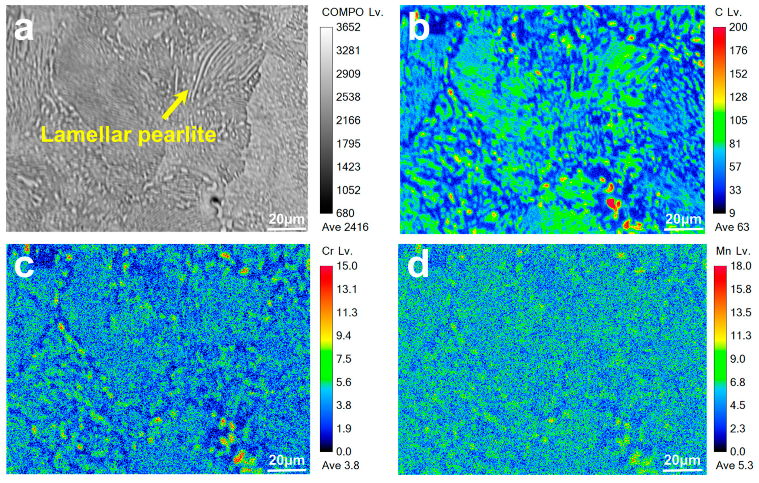
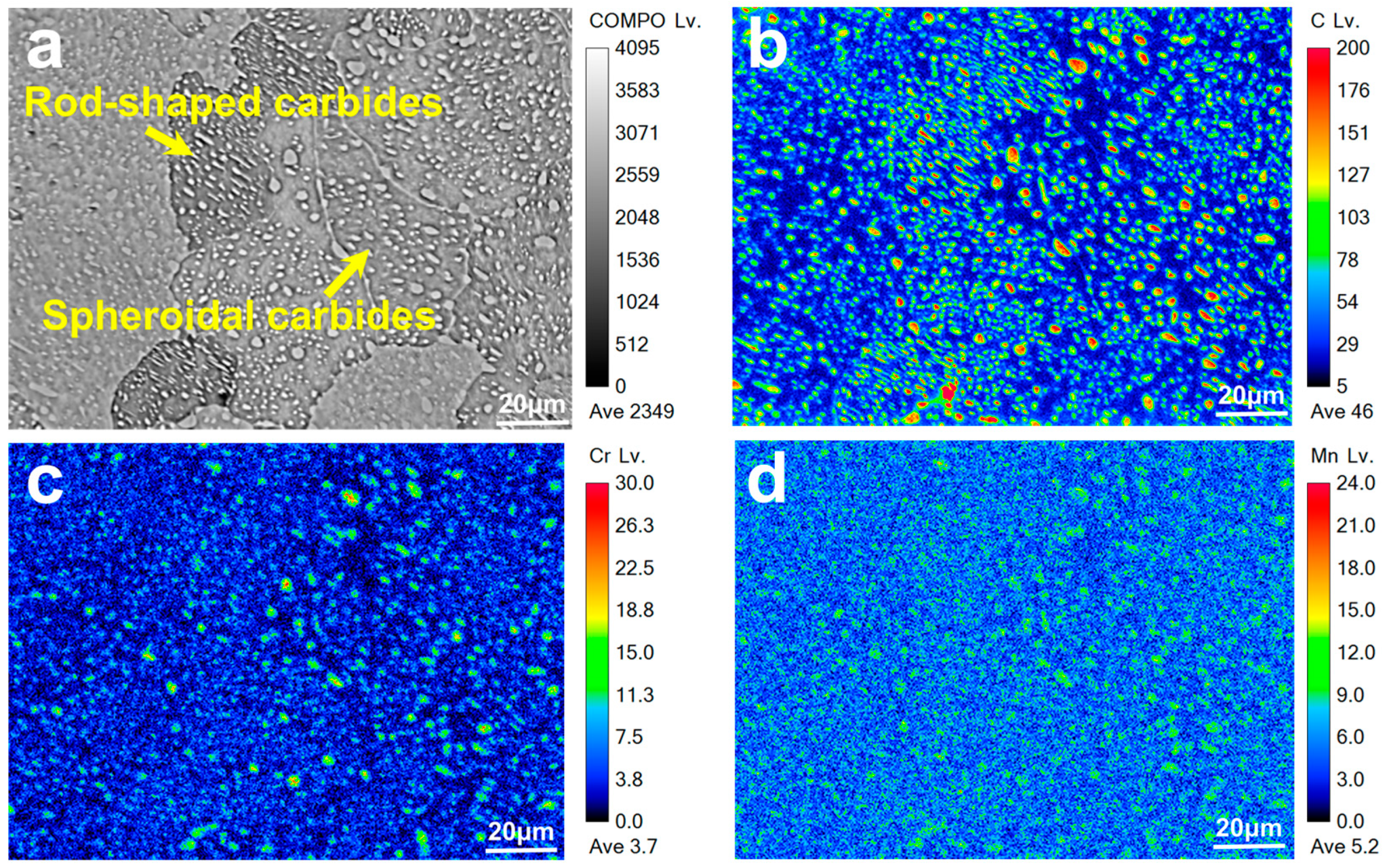
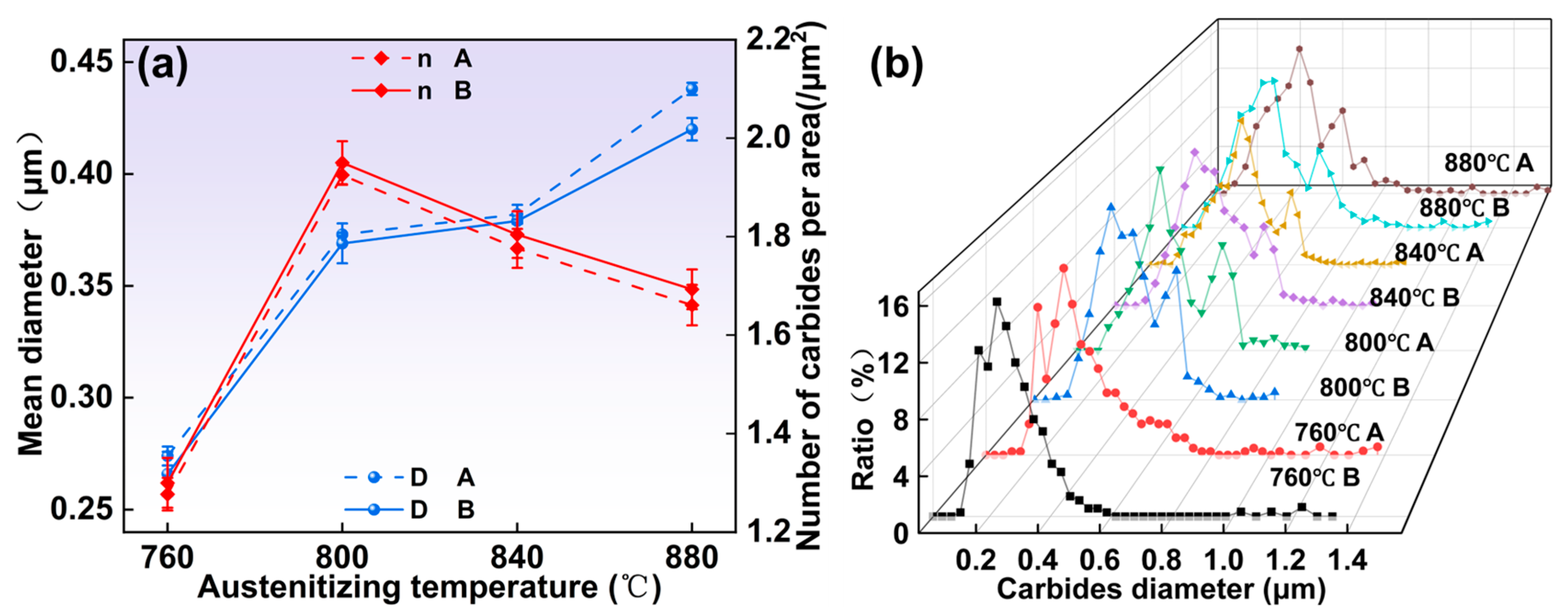
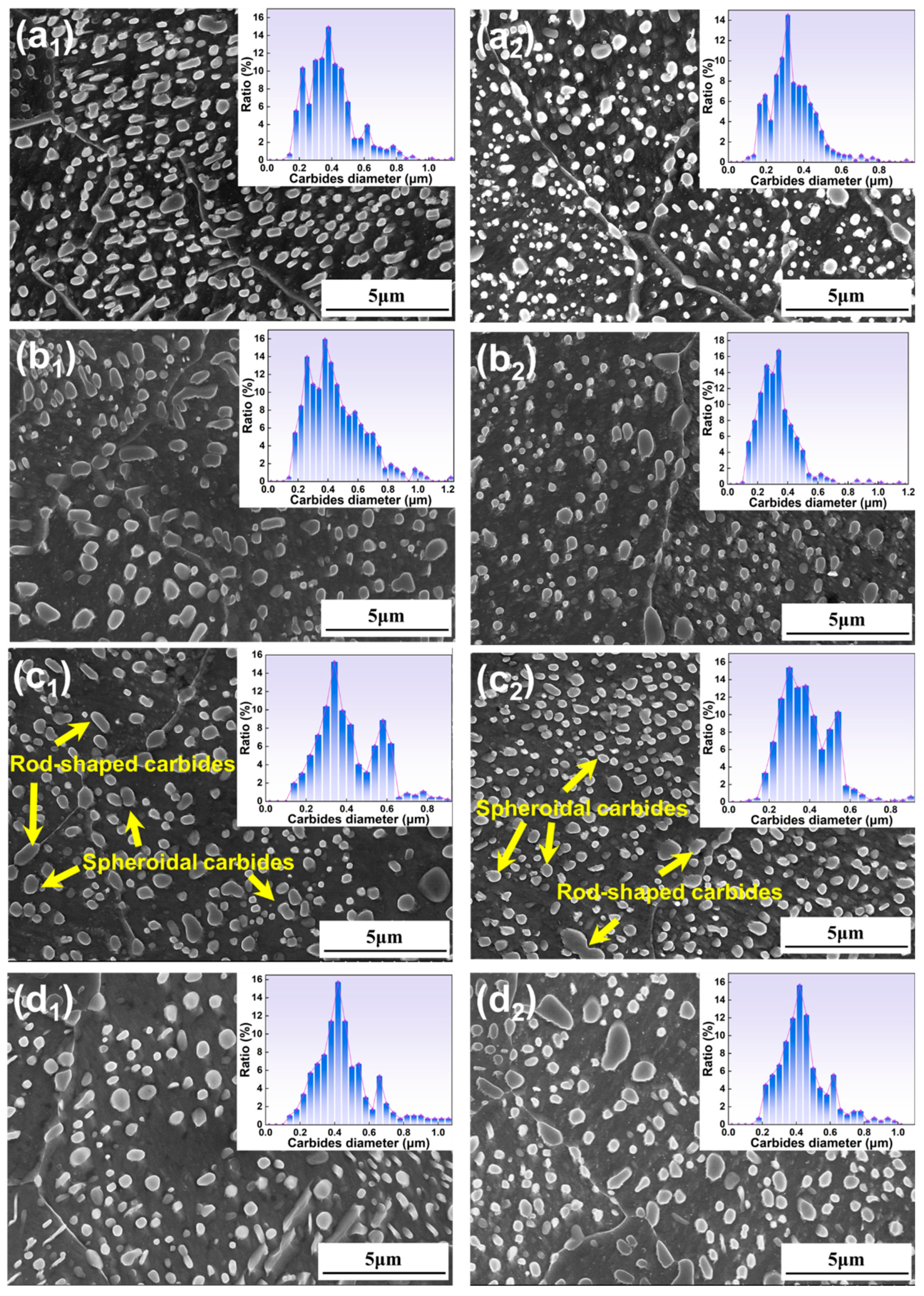
3.1.1. Microstructure Under Different Austenitizing Temperatures

The microstructure of large-section bearing steel specimens at various austenitizing temperatures is presented in Figure 2. It can be seen that at austenitizing temperatures of 760 °C and 880 °C, the spheroidization effect in regions A and B is limited. Three types of carbides are present in the specimen: flake, rod-shaped, and spheroidal. In contrast, at austenitizing temperatures of 800 °C and 840 °C, the spheroidization effect improves significantly, with the majority of carbides becoming spheroidal and only a small number remaining as rod-shaped. This variation highlights the influence of austenitizing temperature on the carbide morphology within the steel.
During the austenitizing stage, the austenitizing temperature plays a crucial role in the dissolution and reprecipitation behavior of carbides [23]. As the austenitizing temperature rises, the solubility of carbon in austenite increases, which in turn accelerates the rate of elemental diffusion. This heightened temperature facilitates a more complete dissolution of the carbides, leading to significant changes in the microstructure of the steel. Understanding these relationships is essential for optimizing the heat treatment process and enhancing the material properties of the bearing steel.
The spheroidization effect is notably poor at austenitizing temperatures of 760 °C and 880 °C, primarily due to the solubility and dissolution rates of the carbides [24]. At 760 °C, the lower temperature results in reduced carbon solubility in austenite and slower diffusion rates, leading to insufficient dissolution of the initial lamellar carbide structure. Conversely, at 880 °C, although most carbides dissolve into the austenite matrix, this limits the nucleation points for the subsequent divorced eutectoid transformation. As the temperature drops below the A1 line, the dominant mechanism shifts to pearlitic transformation, causing the supercooled austenite to convert into lamellar pearlite. In contrast, when the austenitizing temperatures are set at 800 °C and 840 °C, the spheroidization effect improves significantly, indicating that optimal austenitizing temperatures should be maintained within a specific range, with approximately 800 °C being the most suitable. As illustrated in Figure 2a1,a2,d1,d2, the spheroidization effect in region B is superior to that in region A.
To examine the impact of various elements on the spheroidization behavior of carbides, we conducted EPMA tests, with results illustrated in Figure 3 and Figure 4. It can be seen from Figure 3 that at an austenitizing temperature of 760 °C, a lamellar pearlite structure is present in the specimen. At this temperature, carbon is primarily found concentrated in the lamellar pearlitic structure and in a few spherical carbides, while chromium and manganese are predominantly associated with the spherical and rod-like carbides. In Figure 4, at an increased austenitizing temperature of 800 °C, carbon, chromium, and manganese are predominantly located within the carbides, with minimal distribution in the matrix. Notably, chromium is primarily concentrated in the larger spherical carbides. This observation underscores the role of chromium and manganese as carbide-forming elements [25], as they significantly facilitate the spheroidization process of the carbides.
The mean diameter, the number of carbides per area, and carbide particle size distribution were measured, with results illustrated in Figure 5. As shown in Figure 5a, the mean diameter of the carbides (D) increases with rising austenitizing temperatures, while the number of carbides per unit area (n) initially increases before declining. This trend in D differs slightly from the findings of Li et al. [26], primarily due to the less effective spheroidization at 760 °C and 880 °C. Notably, the average size of the carbides in region B is smaller than that in region A, and the density of carbides per unit area is greater in region B compared to region A. This difference can be attributed to the variation in the spacing of the pearlite lamellae between the initial structures of the two regions, as the hot-rolled pearlite lamellar spacing in region A is larger than in region B. The smaller the lamellar spacing, the more potential locations can be provided for the dissolution break of cementite, thereby increasing the number of carbide spheroidal cores available for the decomposition transformation [27]. Additionally, this smaller spacing reduces the diffusion distance for carbon atoms.
The particle size distribution of the carbides is illustrated in Figure 5b, the knot, and the carbide size distribution of individual specimens in Figure 2. The data indicate that the carbides exhibit an approximately bimodal distribution. Most carbides are centered around 0.3 μm, with some larger carbides appearing around 0.6 μm. However, the distribution at 760 °C is somewhat unique; here, the majority of carbides cluster around 0.3 μm, while another portion is found at approximately 0.18 μm. This bimodal distribution arises from differing growth rates of carbides located at the austenite grain boundaries compared to those found within the austenite grains, with intragranular carbides exhibiting a slower growth rate than those formed at the grain boundaries. In addition, the percentage of carbide area with an average carbide size greater than 0.3 μm was calculated as shown in Table 3, and it can be seen from the results that the percentage of large-sized carbides continues to increase as the austenitizing temperature increases.

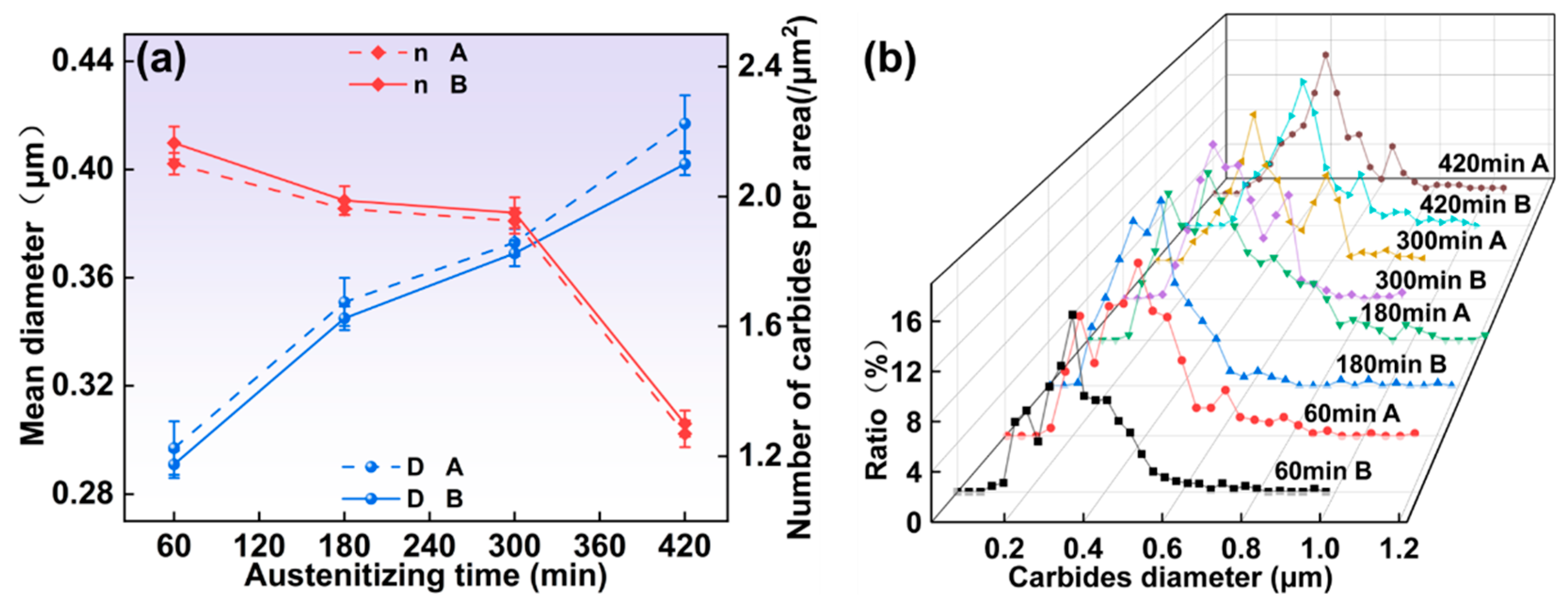
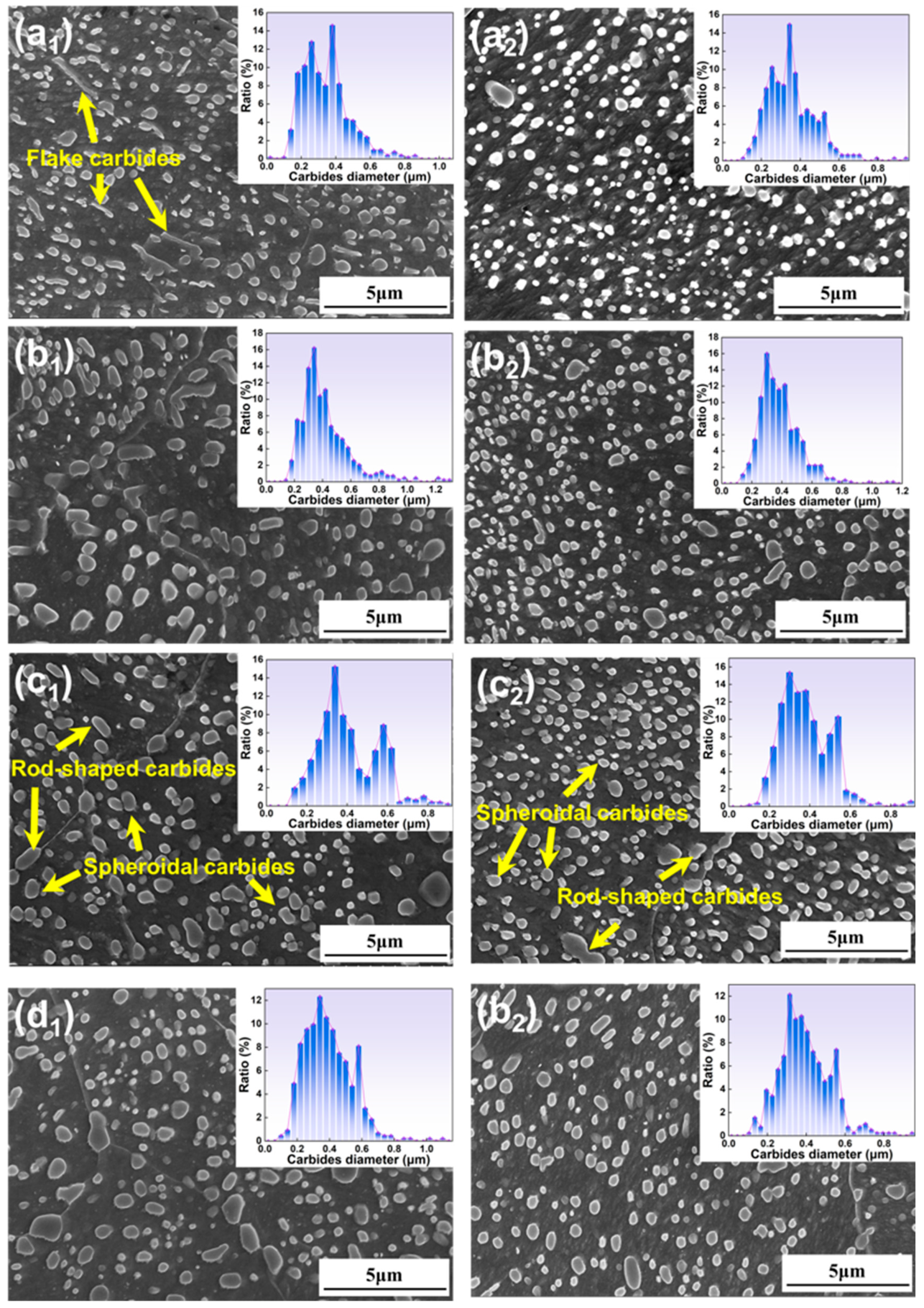
3.1.2. Microstructure Under Different Austenitizing Times

The microstructures of the specimens at various austenitizing times are presented in Figure 6. At an austenitizing time of 60 min, the number of rod-shaped carbides in the specimen is high. As the austenitizing time increases, particularly at 420 min, larger carbides begin to form locally within the specimen. This change is attributed to the extended holding time, during which interfacial energy facilitates the dissolution of smaller carbides, allowing the larger carbides to grow [28].
It is worth noting that when the austenitizing time is 60 min, the rod-shaped carbides in region A are more than in region B. When the time is extended to 420 min, a small amount of large-sized carbides were localized in the specimen in region B, which was not found in region A. This is mainly related to the dissolution of the lamellar cementite. The study of Kamyabi-Gol [29] has shown that with the pearlite lamellar spacing increasing, it is necessary to appropriately extend the austenitizing time. When the austenitizing time is 60 min, the holding time is shorter, the lamellar cementite is not sufficiently fused, and the austenitizing time needs to be extended accordingly, so the A region of the large-sized carbides is more than the B region. When the time is extended to 420 min, the spacing between the lamellar pearlite sheets in the initial organization of region B is relatively small; the end of the austenitizing stage produces undissolved carbide size that is smaller, and small-sized carbides are more likely to precipitate on the surface of the large-sized carbide [30], resulting in the growth of large-sized carbide. The actual production should avoid the emergence of large-sized carbides and therefore needs to control the holding time; it can be greater than 120 min but should not exceed 300 min.
The mean diameter of carbides, the number of carbides per area, and carbide particle size distribution are shown in Figure 7. As shown in Figure 7a, with the extension of austenitizing time, the number of carbides dissolved into the austenite increases, and the carbides can have enough time to grow up [31], so the carbide size gradually increases and the number of carbides per area gradually decreases. It is worth noting that the carbide size of the region A is larger than the B region, the number of carbides per area is smaller than in the B region. This is mainly caused by the difference in initial organization.
As illustrated in Figure 7b, the carbide sizes exhibit a bimodal distribution across various austenitizing durations. At an austenitizing time of 60 min, most carbides distribute around 0.3 μm, with a smaller group of carbides around 0.18 μm. The presence of these smaller carbides likely indicates the formation of new carbide particles. As the austenitizing time increases, the sizes of the carbides gradually enlarge due to the Ostwald ripening mechanism, resulting in a higher population of carbides around 0.6 μm. By the time the austenitizing duration reaches 420 min, the quantity of carbides smaller than 0.2 μm significantly decreases. This reduction is primarily attributed to diminished carbon segregation with extended austenitizing time, which inhibits the formation of new carbides [32]. Additionally, the coarsening of existing carbides further contributes to the decline in the number of small-sized carbides; the quantitative results in Table 4 also demonstrate that this is the case.

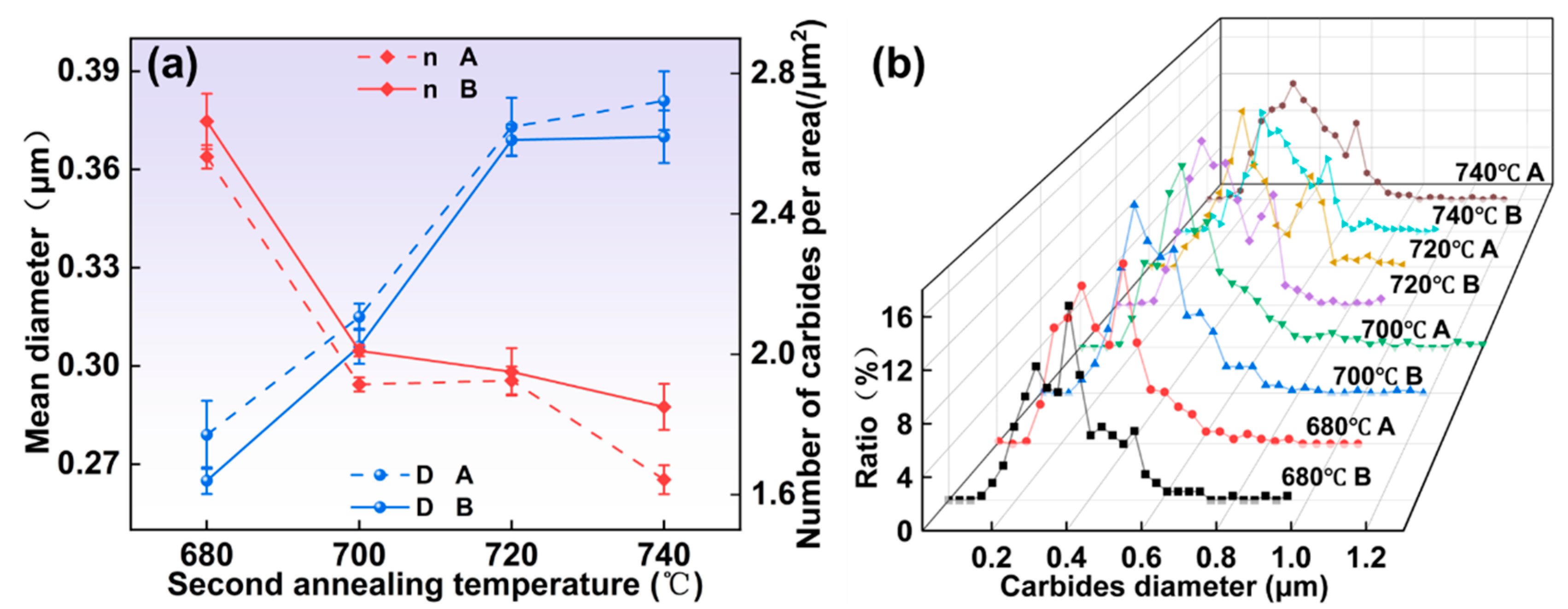
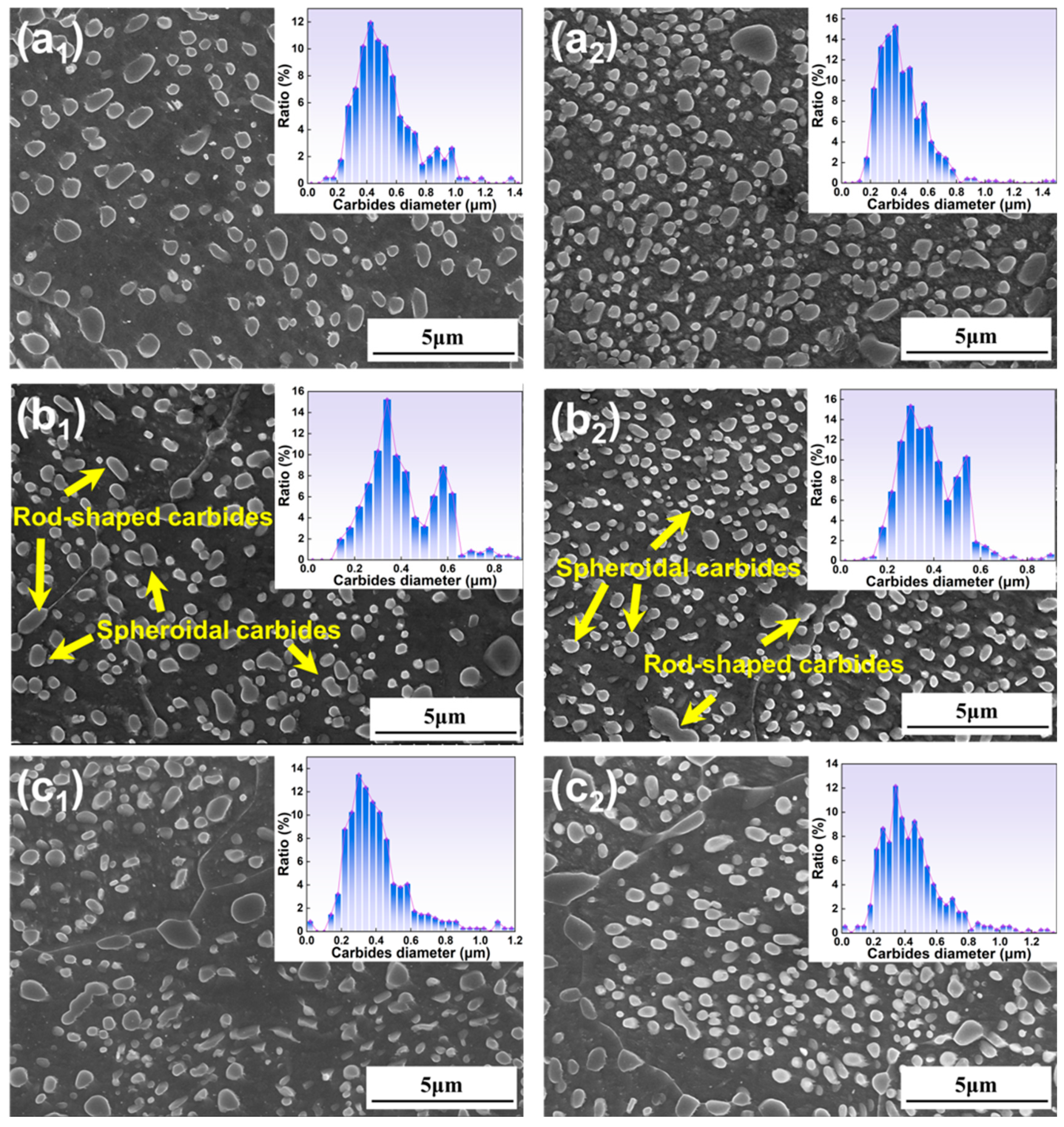
3.1.3. Microstructure Under Different Second Annealing Temperatures

The microstructures of the specimens at different second annealing temperatures are shown in Figure 8. It can be seen that when the second annealing temperature is lower, a small amount of carbides similar to lamellar carbides appeared locally in the specimen, as shown in Figure 8a1, but not like the austenitizing temperature of 760 °C, a large number of lamellar carbides appeared. This difference is primarily attributed to the mechanisms of pearlite transformation and divorced eutectic transformation. The temperature for the divorced eutectoid transformation is higher than that for the pearlite transformation, which explains the presence of limited lamellar carbides at 680 °C. When the secondary annealing temperature is increased to 700 °C, larger rod-shaped carbides are still evident, suggesting that further increases in the secondary annealing temperature are necessary. Experimental treatments were conducted above the A1 temperature line, as shown in Figure 8d1,d2. These results indicate a reduction in the number of carbides per unit area compared to lower temperatures. This reduction can be attributed to the fact that at 740 °C, the material remains in the austenitizing phase, during which a considerable amount of carbides remains dissolved in the austenite, leading to a lower density of carbides in comparison to other annealing temperatures.
A comparison of Figure 8a1,a2 shows that despite the second annealing temperature of 680 °C, no obvious flake carbides appeared in the specimens in region B, which is mainly due to the fact that the pearlitic lamellae in region B are more easily dissolved.
The mean diameter of carbides, the number of carbides per area and carbides particle size distribution are shown in Figure 9. As shown in Figure 9a, increasing the secondary annealing temperature leads to a gradual increase in carbide size and a corresponding decrease in the number of carbides per area. This trend can be attributed to the enhanced diffusion rate of carbides at higher temperatures [33]. Notably, at 700 °C, there is a significant change in the number of carbides within the unit area; however, no abnormal growth of carbides is observed. This behavior underscores the influence of temperature on carbide evolution during the spheroidization annealing process.
It can be clearly seen that the carbide size in the specimen in region B is smaller than that in region A, and the number of carbides per unit area is higher than that in region A. This is mainly because the number of undissolved carbide cores formed by lamellar cementite dissolution fracture is larger per unit area, which can provide more carbide nucleation points [34].
As illustrated in Figure 9b, the peak of the carbide size distribution shifts toward larger sizes as the secondary annealing temperature increases. In addition, the area percentage of carbides with an average size larger than 0.3 μm at different secondary annealing temperatures was quantified, and the results are shown in Table 5. It can be seen that with the increase in secondary annealing temperature, the percentage of large-sized carbides is increasing, which is consistent with the conclusion of carbide size distribution. At a temperature of 680 °C, carbides smaller than 0.2 μm begin to appear in the microstructure. This phenomenon occurs primarily due to the lower temperature and significant degree of subcooling, which together create a strong driving force for carbide precipitation. Consequently, these conditions promote the formation and growth of new carbides, highlighting the critical role of annealing temperature in carbide evolution during the spheroidization process.
While lowering the second annealing temperature can effectively reduce carbide size, it can also lead to the formation of some flaker carbides. Additionally, the temperature necessary for the divorced eutectoid transformation exceeds that required for pearlite transformation. Therefore, it is essential to increase the second annealing temperature to prevent the lamellar pearlite phase from forming. Based on experimental findings, it is recommended that the secondary annealing temperature be maintained around 720 °C to achieve optimal carbide characteristics without promoting unwanted transformations.

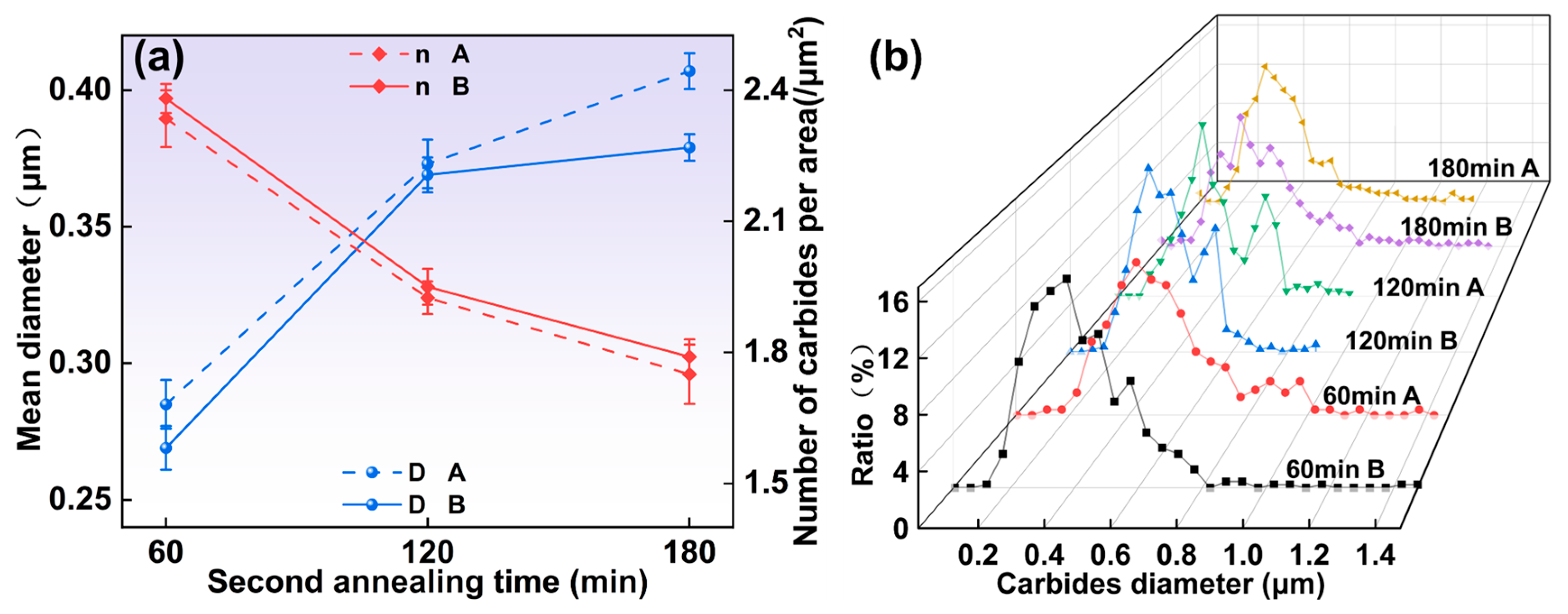
3.1.4. Microstructure Under Different Second Annealing Times

The microstructures of the specimens under different secondary annealing times are shown in Figure 10. It can be found that all the specimens have good spheroidization. However, when the secondary annealing time is 180 min, large-size spherical carbides appear in the specimens, as shown in Figure 10a1,a2. These larger carbides can lead to stress concentration, which is undesirable. Therefore, to optimize microstructural characteristics, it is recommended to limit the secondary annealing time to approximately 120 min.
The mean diameter of carbides, the number of carbides per area, and carbide particle size distribution of the specimens under different secondary annealing times were statistically analyzed by means of quantitative metallography, and the test results are shown in Figure 11. The results, illustrated in Figure 11a, reveal that the average size of the carbides increases with a prolonged second annealing time, while the number of carbides per area decreases. This trend can be attributed to the enhanced diffusion of carbides as the annealing duration extends [35]. Notably, in region A, the carbide size continues to grow with secondary annealing times up to 180 min, exhibiting a larger size compared to region B. Furthermore, Figure 11b illustrates the carbide size distribution, which maintains a bimodal pattern. This bimodal distribution arises from the differing growth rates of the carbides at this stage [36]. In addition, the area percentage of carbides with an average carbide size larger than 0.3 μm was measured for different secondary annealing times, and the results are shown in Table 6. It can be seen that with the increase in secondary annealing time, the percentage of large-size carbides gradually increases.
In this study, we investigated the carbide evolution and mechanical properties of large-section 1.0C-1.5Cr bearing steel during spheroidization annealing, focusing on specific temperature and time parameters. The experiments revealed that an austenitizing temperature of 800 °C, combined with a duration of 300 min, followed by a second annealing at 720 °C for 120 min, yields optimal spheroidization results for the large-section bearing steel. As shown in Figure 12 for the isothermal spheroidizing annealing process microstructure evolution law. The microstructure of the specimen before spheroidization annealing is lamellar pearlite and a few reticulated carbides, as shown in Figure 12(1). With the increase in temperature, when the temperature reaches the A1 line, the lamellar cementite will undergo dissolution fracture, producing several small lamellar carbides, as shown in Figure 12(2). From the energy point of view, the transformation of lamellar cementite into spherical carbides can significantly reduce the surface energy [37], so these broken carbides will spontaneously spheroidize when held during the austenitizing stage, as shown in Figure 12(3). If the austenitizing time is sufficiently adequate, the carbides will appear coarsened as shown in Figure 12(4). These spheroidized carbides retained in the austenitizing stage, undissolved carbides, are at the core of the realization of the dissociated eutectic transformation and will become the nucleation point of subsequent carbides during subsequent cooling and holding. When the austenitizing stage is over, the temperature will be lowered until the secondary annealing temperature is reached. When the temperature is decreased below the A1 line, the austenite in the carbon-poor zone will be transformed into ferrite, and when the α-γ interface passes through these carbides, the carbides will be coarsened, as shown in Figure 12(5). It is worth noting that in the austenite there are localized carbon-rich zones; as the temperature decreases, there will be new carbides localized in carbon-rich zones precipitation, as shown in Figure 12(6). In the secondary annealing stage, as the secondary annealing time increases, the spherical carbides will be dissolved in the small-sized carbides and the large-sized carbides will grow up under the action of the Ostwald ripening mechanism, as shown in Figure 12(7).

3.2. Model Building

Based on the analysis of the above results, it can be clearly observed that the trend of D shows an opposite direction to n. However, on the whole, the volume fraction of carbide (V) tends to maintain a stable value, which is visually demonstrated in Figure 13a. Specifically, the average volume fraction of carbides was maintained at around 24.2%. After undergoing the spheroidal annealing treatment, the carbides are mainly present in spherical form, which occupies the majority. Therefore, (V) can be approximated by the following equation:
V = π 6 D 3 N ,
where N represents the number of carbides per unit volume. Although it is difficult to directly measure the value of N, we can make an approximate estimate of it from the n value. Given that volume is a measure of three-dimensional space and area is a measure of two-dimensional space, there is a linear relationship between N and n 3 2 . Furthermore, in order to more accurately reflect the inhomogeneity of the carbide distribution in the material, a correction factor needs to be introduced when using the n value for N. This correction factor is integrated into the following equation to more accurately describe the relationship:
N = a 1 n 3 2 + a 2 ,
where a1 and a2 are correction factors. It should be noted that the introduction of the correction factor also offsets the error caused by Equation (2). Substituting Equation (3) into Equation (2) yields (4).
D - 3 = π a 1 6 V n 3 2 + π a 2 6 V .
Therefore, there should be a linear relationship between D−3 and n3/2. This is shown in Figure 13b, where the dots represent the experimental data and the solid line represents the fitted curve.
Based on the slope and intercept of Figure 13b, Equation (4) can be written as follows:
D = ( 8.85 n 3 2 1.697 ) 1 3 .
The values of a1 and a2 can be determined from the slope versus intercept of the fitted curves. Specifically, under the condition that the carbide volume fraction reaches 24.2%, the value of a1 is 4.09, while the value of a2 is −0.785. It is worth noting that even though the set value of n is zero, the value of N calculated according to Equation (3) is not zero. This phenomenon is mainly attributed to the fact that the distribution of carbides in the actual material is not completely homogeneous, and the shape of some carbides deviates from the ideal spherical shape. In addition, the volume fraction of carbides is always maintained in a non-zero state in practical situations, implying that the n value cannot be zero in reality. Therefore, despite this computational bias, its overall effect on the final results is relatively small.
As shown in Figure 13c, good agreement is presented between the measured values of D and the values calculated through Equation (5). The validity and accuracy of the model are strongly demonstrated by this result. It should be noted in particular that obtaining the measured value of D tends to be time-consuming compared to the measured value of n. Therefore, utilizing this model to quantify D becomes an efficient and convenient method.

3.3. Effect of Carbide Size and Primary Cast Billet Position on Mechanical Properties

Figure 14 illustrates how the tensile strength and elongation vary with the mean diameter of carbides, alongside the stress–strain curves for various conditions. As shown in Figure 14a,b, both tensile strength and elongation decrease as the size of the carbides increases. This reduction can be attributed to two main factors. First, larger carbides act as sites for stress concentration during the cold deformation, making the material more susceptible to cracking and crazing under stress. Second, the presence of larger carbides creates a strain mismatch between the carbides and the surrounding ferrite matrix, resulting in the formation of micro-voids at their interface [38]. Consequently, specimens containing larger carbide particles exhibit an increased likelihood of fracture.
As shown in Figure 14a, in the elliptical region, the tensile strength is much higher than the other parameters when the austenitizing temperature is 760 °C and 880 °C. This is due to the poor spheroidization and the presence of lamellar pearlite organization in the specimen. It is worth noting that the tensile strength of region B is higher than that of region A, but the elongation is lower than that of region A. The high tensile strength is due to the second phase strengthening of carbides, which can be estimated by the Orowan equation [39] as follows:
σ p r e p = 0.8 M μ b L p r e p ,
where M is the average Taylor factor, μ is the shear modulus, b is the burgers vector, and Lprep is the average particle spacing, which is approximated as Lprep = 4r/3f, where r and f denote the particle radius and volume fraction, respectively. For the same steel with equal values of M, μ, b, and f, the carbides at the center position are small in size, uniformly and densely distributed, and the low elongation is due to the fact that the smaller and more numerous the carbides are, the stronger the impediment to dislocation slip.
The stress–strain curves of selected specimens are shown in Figure 14c,d, and it can be clearly seen that the three groups of selected specimens show two kinds of yielding behaviors. From continuous yielding at austenitizing temperatures of 760 °C and 880 °C to discontinuous yielding at an austenitizing temperature of 800 °C, the specimens with other parameters also showed the same yielding behavior as at an austenitizing temperature of 800 °C. At 760 °C and 880 °C, most carbon remains dissolved within the matrix, which accounts for the continuous yielding observed. Conversely, at 800 °C, the carbon appears as dispersed carbides on the matrix surface, influencing the mechanical response of the material. This transition highlights the impact of spheroidization annealing treatment on the microstructure and the resulting mechanical properties of the bearing steel.

3.4. Fracture Behavior

The tensile specimens of all samples were examined using a scanning electron microscope to analyze their fracture morphology. Most specimens exhibited fine dimple patterns, while some displayed a combination of extensive facet-like cleavage areas and limited fine dimple features. Figure 15a,b clearly illustrate the lamellar pearlite structure, along with fine carbide precipitates visible in the ligamentous fossa pits in the magnified images as shown in Figure 15d,e. Notably, for the specimen subjected to secondary annealing for 420 min, large spherical carbides measuring approximately 0.76 μm were identified within the dimples, as shown in Figure 15f. During the plastic deformation, the large-size carbide particles are prone to interfacial mismatch with the matrix, and micropores are more likely to form under low stress. These pores grow and interconnect during plastic deformation, eventually triggering macroscopic fracture. This process shortens the stage at which the material reaches its maximum tensile strength, leading to a reduction in overall strength. As shown in Figure 15g,h for the fracture morphology of the specimen in region B, at the secondary annealing temperature of 700 °C, the fracture morphology of the specimen is characterized by uniformly distributed tiny tough nests, which exhibit ductile fracture, which is similar to that shown in Figure 15a–f. However, as shown in Figure 15i, while the fracture surface primarily comprises disintegrated areas and ridges, there are still localized tough dimples, illustrating a mixed mode of brittle and ductile fracture behavior.

4. Conclusions

In this work, the effects of various factors such as austenitizing temperature, austenitizing time, secondary annealing temperature, and secondary annealing time on the size and distribution of carbides in the 1/2 position and the center position of 1.0C-1.5Cr large cross-section bearing steel were comprehensively investigated. The relationship between the mean diameter of carbides and the resulting tensile strength and elongation was analyzed. In addition, the fracture behavior was evaluated to provide insight into the material properties. The findings from this research lead to the following conclusions:
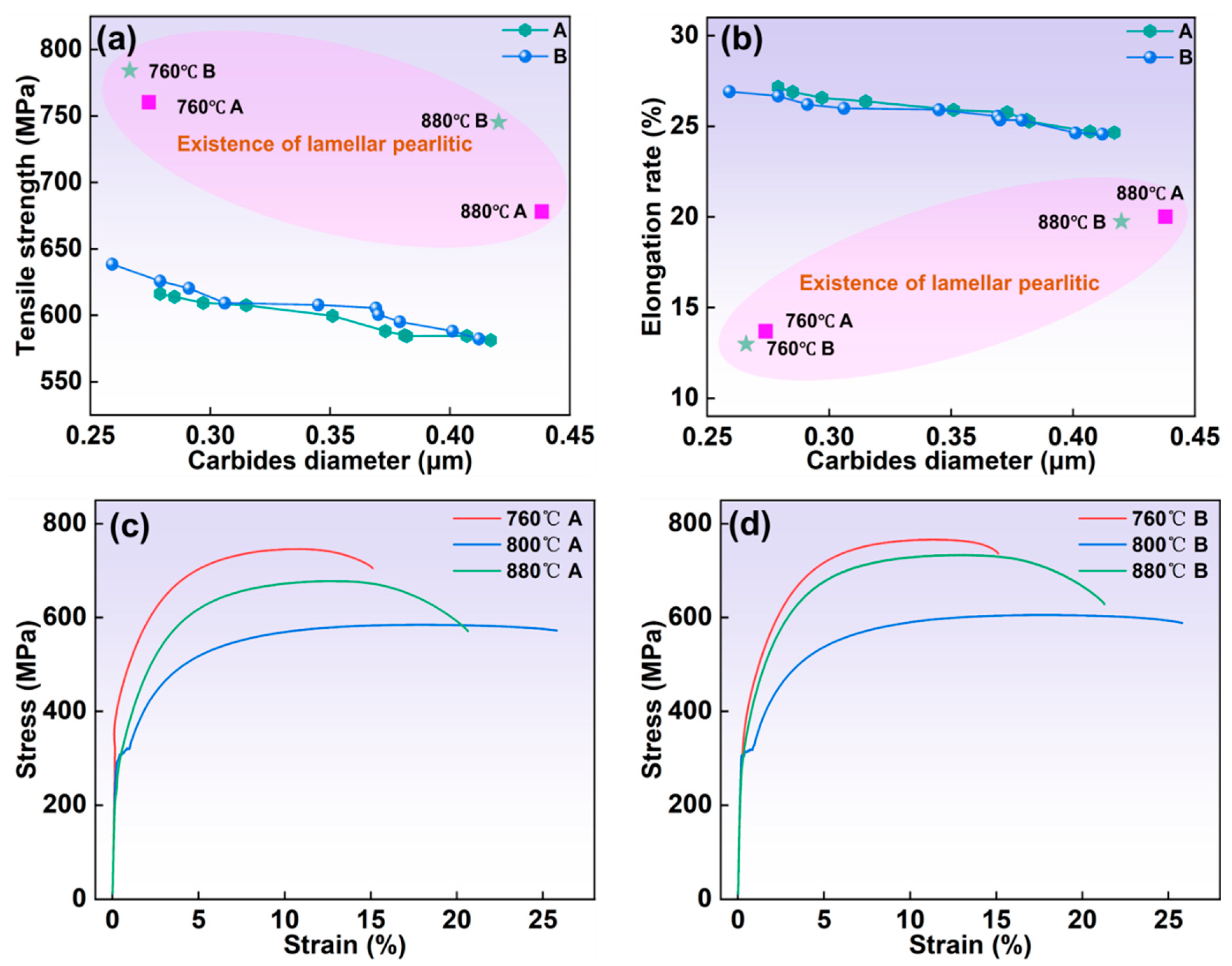
  • As the austenitizing and second annealing stages progress, with increased temperatures and extended holding times, the average carbide size in both the 1/2 and center positions gradually increase, while the number of carbides per area decreases. Carbides in the center position are smaller in size but denser compared to those in the 1/2 region. At austenitizing temperatures of 760 °C and 880 °C, the persistence of lamellar pearlite structures can impede further mechanical processing. Hence, maintaining the austenitizing temperature within an optimal range, ideally around 800 °C, is critical. The austenitizing time should be between 120 and 300 min, while the second annealing temperature should be approximately 720 °C with a duration of around 120 min for optimal results.
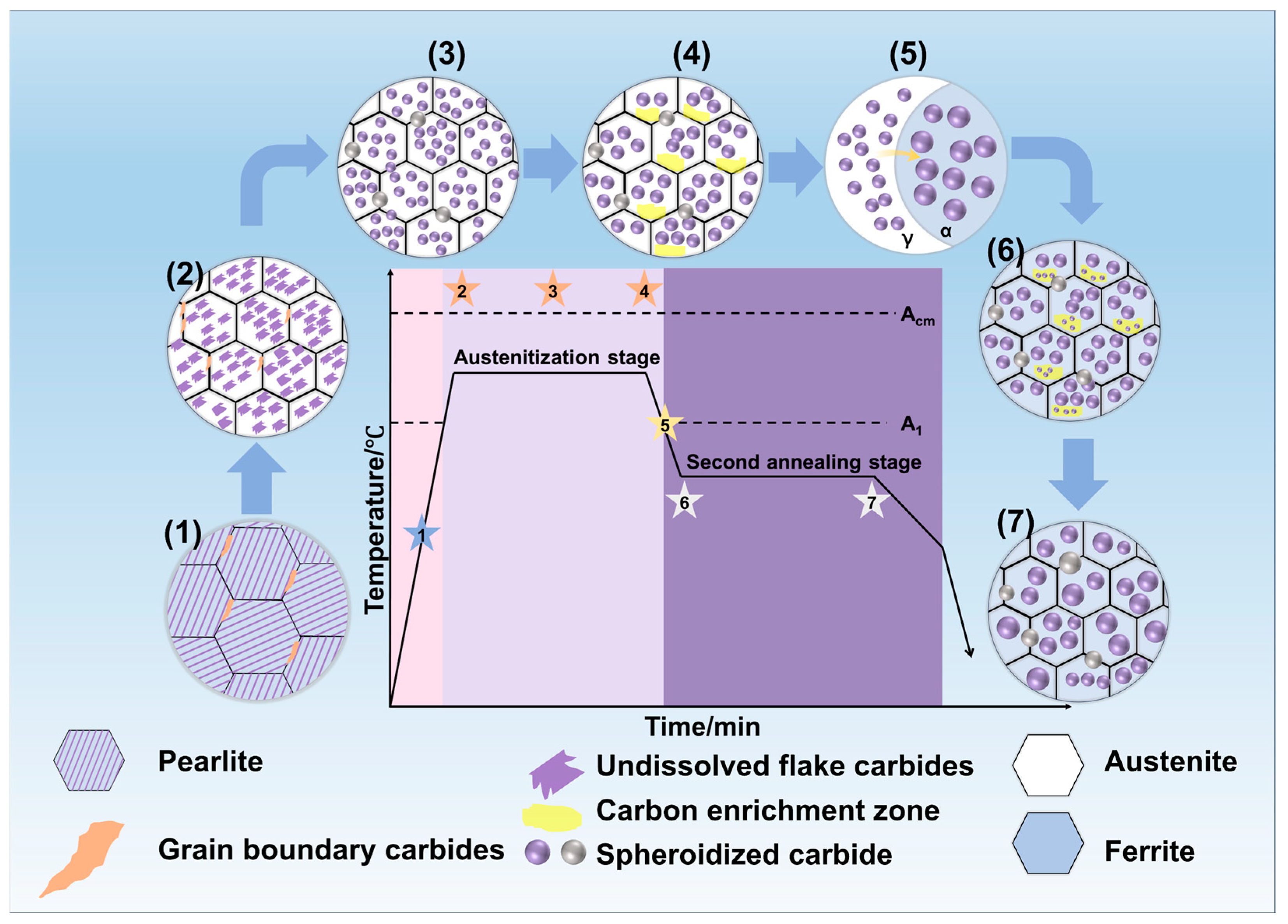
  • All specimens exhibit a bimodal distribution of carbides, which shifts toward larger sizes as temperature and time increase. This bimodal pattern is primarily due to the cooling process, wherein the new carbides nucleate and grow in localized carbon-rich regions, combined with varying carbide growth rates.
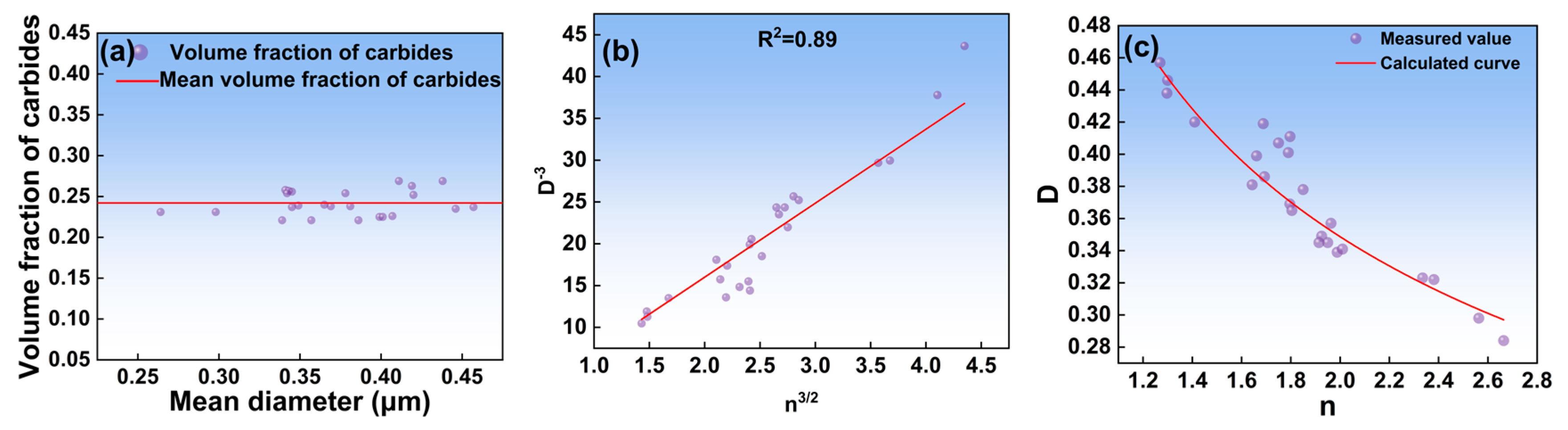
  • The mean diameter of carbides and the number of carbides per area were modeled. The relationship between them can be expressed as D = ( 8 . 85 n 3 2     1 . 697 ) 1 3 .
  • As the mean diameter of carbides increases, both the tensile strength and elongation decrease. Specimens austenitized at 760 °C and 880 °C, whether from the 1/2 or center positions, exhibit continuous yielding behavior, which results in higher strength that can be detrimental to machining. In contrast, other specimens show discontinuous yielding, indicating a more favorable distribution of carbon along the ferrite surface and better carbide formation, ultimately improving machinability.
  • Fracture analysis of the tensile specimens showed that the fracture of most specimens showed uniform small toughness dimples, reflecting the typical toughness fracture characteristics. However, some specimens showed large carbides of about 0.76 μm in the fracture, which would lead to early nucleation of micropores due to interfacial mismatch, resulting in low-stress fracture and strength reduction. In addition, the fracture morphology of some specimens is characterized by a mixture of fracture surface and tough dimples, which indicates that both brittle and ductile fractures exist in the fracture process.

Author Contributions

Conceptualization, P.D., Z.Y. and J.Z.; methodology, P.D., C.S. and J.Z.; software, P.D. and S.Y.; validation, P.D. and J.Z.; formal analysis, P.D. and J.Z.; investigation, P.D. and S.Y.; resources, Z.Y.; data curation, P.D.; writing—original draft preparation, P.D.; writing—review and editing, P.D. and C.S.; visualization, P.D.; supervision, C.S.; project administration, C.S. and Z.Y.; funding acquisition, Z.Y. All authors have read and agreed to the published version of the manuscript.

Funding

This research was financially supported by the National Key Research and Development Program of China (Grand No. 2023YFB3710103) and the Science and Technology Program of Jiangsu Provincial Administration for Market Regulation (Grand Nos. KJ2024004, KJ2024034, KJ2025004). Thanks to Xiaolin Zhu and Qian Chen for their help in our scientific research.

Data Availability Statement

The original contributions presented in this study are included in the article. Further inquiries can be directed to the corresponding author.

Conflicts of Interest

The authors declare no conflict of interest.

References

  1. de Azevedo, H.D.M.; Araújo, A.M.; Bouchonneau, N. A review of wind turbine bearing condition monitoring: State of the art and challenges. Renew. Sust. Energ. Rev. 2016, 56, 368–379. [Google Scholar] [CrossRef]
  2. Ding, H.H.; Mermertas, U.; Hagemann, T.; Schwarze, H. Calculation and validation of planet gear sliding bearings for a three-stage wind turbine gearbox. Lubricants 2024, 12, 95. [Google Scholar] [CrossRef]
  3. Yang, B.; Liu, B.X.; Fan, K.Y.; Zhang, B.Y.; Ji, P.G.; Feng, J.H.; Tong, H.C.; Yin, F.X. Obvious different formability and mechanical properties of warm caliber rolling Q345 steel with normalized and tempered states. Mater. Sci. Eng. A-Struct. Mater. Prop. Microstruct. Process. 2023, 887, 12. [Google Scholar] [CrossRef]
  4. Yan-kun, S.; Di, W. Effect of Ultra-Fast Cooling on Microstructure of Large Section Bars of Bearing Steel %J Journal of Iron and Steel Research (International). J. Iron Steel Res. (Int.) 2009, 16, 61–65,80. [Google Scholar]
  5. Härtel, S.; Awiszus, B.; Graf, M.; Nitsche, A.; Böhme, M.; Wagner, M.F.X.; Jirkova, H.; Masek, B. Influence of austenite grain size on mechanical properties after quench and partitioning treatment of a 42SiCr steel. Metals 2019, 9, 577. [Google Scholar] [CrossRef]
  6. Yuan, Q.Q.; Yin, H.Q.; Qiao, Z.Q.; Zhang, C.; Wang, Y.W.; Zhang, R.J.; Jiang, X.; Khan, D.F.; Li, D.; Liang, J.B.; et al. Homogenization Treatment and Plastic Deformation Improve the Carbide Homogeneity of M42 High-Speed Steel. Steel Res. Int. 2024, 95, 12. [Google Scholar] [CrossRef]
  7. Teng, H.; Qian, S.S.; Xie, J.H.; Zhao, H.S.; Wei, X.C.; Dong, H. Effect of Spheroidizing Annealing Process on Microstructure and Properties of Quenching and Tempering 60Cr16MoMA Martensitic Stainless Steel. Steel Res. Int. 2024, 95, 2300781. [Google Scholar] [CrossRef]
  8. Huang, H.; De Cooman, B.C. Influence of the Initial Microstructure on the Spheroidization of SAE 52100 Bearing Steel. Steel Res. Int. 2016, 87, 112–125. [Google Scholar] [CrossRef]
  9. Zhang, C.C.; Yi, X.L.; Yuan, Q.Q.; Wang, L. Microstructure and mechanism of three spheroidizing treatment for the carbide of GCr15 steel. In Proceedings of the 3rd International Conference on Manufacturing Science and Engineering (ICMSE 2012), Xiamen, China, 27–29 March 2012; p. 351. [Google Scholar]
  10. Huang, Z.Y.; Du, L.X.; Li, M.Z.; Fu, S.Y.; Lu, J.N. Study on rolling and hot delivery spheroidizing annealing of GCr15 bearing steel. J. Mater. Eng. Perform. 2023, 32, 7779–7784. [Google Scholar] [CrossRef]
  11. Ankit, K.; Mukherjee, R.; Nestler, B. Deviations from cooperative growth mode during eutectoid transformation: Mechanisms of polycrystalline eutectoid evolution in Fe–C steels. Acta Mater. 2015, 97, 316–324. [Google Scholar] [CrossRef]
  12. Verhoeven, J.D. The role of the divorced eutectoid transformation in the spheroidization of 52100 steel. Metall. Mater. Trans. A-Phys. Metall. Mater. Sci. 2000, 31, 2431–2438. [Google Scholar] [CrossRef]
  13. Liu, K.Q.; Zhang, X.J.; Song, X.Y.; Zhao, L.; Zhu, L. Evaluation and improvement of pearlite microstructure and mechanical properties in 45Cr4NiMoV and 50Cr5NiMoV steels. J. Iron Steel Res. Int. 2022, 29, 1995–2005. [Google Scholar] [CrossRef]
  14. Li, Z.X.; Li, C.S.; Kim, S.H.; Suh, D.W. Influence of initial pearlite morphology on the microstructure evolution during heat treatment of 1.0C-1.5Cr steel. Met. Mater. Int. 2019, 25, 9–17. [Google Scholar] [CrossRef]
  15. Zhang, G.H.; Chae, J.Y.; Kim, K.H.; Suh, D.W. Effects of Mn, Si and Cr addition on the dissolution and coarsening of pearlitic cementite during intercritical austenitization in Fe-1mass%C alloy. Mater. Charact. 2013, 81, 56–67. [Google Scholar] [CrossRef]
  16. Kim, K.H.; Lee, J.S.; Lee, D.L. Effect of silicon on the spheroidization of cementite in hypereutectoid high carbon chromium bearing steels. Met. Mater. Int. 2010, 16, 871–876. [Google Scholar] [CrossRef]
  17. Lee, S.; Kim, S.; Hwang, B.; Lee, B.S.; Lee, C.G. Effect of carbide distribution on the fracture toughness in the transition temperature region of an SA 508 steel. Acta Mater. 2002, 50, 4755–4762. [Google Scholar] [CrossRef]
  18. Caballero, F.; de Andrés, C.G.; Capdevila, C. Characterization and morphological analysis of pearlite in a eutectoid steel. Mater. Charact. 2000, 45, 111–116. [Google Scholar] [CrossRef]
  19. Pang, J.; Wang, G.; Yi, H. Effect of isothermal annealing on microstructure and hardness of low-density bearing steel. J. Iron Steel Res. 2020, 32, 1077–1083. [Google Scholar]
  20. Chen, M.; Zhang, C.; Zhang, G.H.; Zhou, J.; Hu, F.; Wu, K.M. Acceleration of Spheroidization in Low-Density Ultrafine Pearlitic Steel by κ-Carbide. Steel Res. Int. 2024, 95, 2300564. [Google Scholar] [CrossRef]
  21. Hong, L.X.; Jin, Q.Y.; Li, X.S.; Huang, Y.Z. Image and medical annotations using non-homogeneous 2D ruler learning models. Comput. Electr. Eng. 2016, 50, 102–110. [Google Scholar] [CrossRef]
  22. Wu, D.; Li, Z. A New Pb-Free Machinable Austenitic Stainless Steel. J. Iron Steel Res. Int. 2010, 17, 59–63. [Google Scholar] [CrossRef]
  23. Ning, A.G.; Liu, Y.; Gao, R.; Yue, S.; Wang, M.B.; Guo, H.J. Effect of austenitizing condition on mechanical properties, microstructure and precipitation behavior of AISI H13 steel. J. Iron Steel Res. Int. 2024, 31, 143–156. [Google Scholar] [CrossRef]
  24. Qian, M. In-situ observations of the dissolution of carbides in an Fe-Cr-C alloy. Scr. Mater. 1999, 41, 1301–1303. [Google Scholar] [CrossRef]
  25. Hou, Z.Y.; Babu, R.P.; Hedström, P.; Odqvist, J. Early stages of cementite precipitation during tempering of 1C-1Cr martensitic steel. J. Mater. Sci. 2019, 54, 9222–9234. [Google Scholar] [CrossRef]
  26. Li, Z.X.; Li, C.S.; Zhang, J.; Qiao, B.; Li, Z.Z. Effects of annealing on carbides size and distribution and cold formability of 1.0C-1.5Cr bearing steel. Metall. Mater. Trans. A-Phys. Metall. Mater. Sci. 2015, 46A, 3220–3231. [Google Scholar] [CrossRef]
  27. Michal, G.M.; Novak, M.D. The divorced eutectoid transformation and spheroidization of steels. Symp. Thermodyn. Kinet. Charact. Model. Austenite Form. Decompos. 2003, 397–413. [Google Scholar]
  28. Zhang, Z.Q.; Jing, H.Y.; Xu, L.Y.; Han, Y.D.; Zhao, L.; Lv, X.Q.; Zhang, J.Y. The impact of annealing temperature on improving microstructure and toughness of electron beam welded duplex stainless steel. J. Manuf. Process. 2018, 31, 568–582. [Google Scholar] [CrossRef]
  29. Kamyabi-Gol, A.; Sheikh-Amiri, M. Spheroidizing kinetics and optimization of heat treatment parameters in ck60 steel using taguchi robust design. J. Iron Steel Res. Int. 2010, 17, 45–52. [Google Scholar] [CrossRef]
  30. Yang, H.B.; Wang, Y.M.; Luo, L.; Zhang, P.P. Ostwald Growth of Carbides in Cyclic Annealing Process of GCr15 Bearing Steel. In Proceedings of the 4th International Conference on Technology of Architecture and Structure (ICTAS 2011), Xi’an University of Architecture and Technology, Xi’an, China, 22–24 September 2021; pp. 1805–1808. [Google Scholar]
  31. Lu, X.; Fang, F.; Zhang, Y.X.; Wang, Y.; Yuan, G.; Xu, Y.B.; Misra, R.D.K.; Zhang, W.N.; Wang, G.D. Microstructure and magnetic properties of strip-cast grain-oriented 4.5%Si steel under isochronal and isothermal secondary annealing. J. Mater. Sci. 2018, 53, 2928–2941. [Google Scholar] [CrossRef]
  32. Erdogan, M.; Kilicli, V.; Demir, B. The influence of the austenite dispersion on phase transformation during the austempering of ductile cast iron having a dual matrix structure. Int. J. Mater. Res. 2008, 99, 751–760. [Google Scholar] [CrossRef]
  33. Di, H.; Zhang, X.; Wang, G.; Liu, X. Spheroidizing kinetics of eutectic carbide in the twin roll-casting of M2 high-speed steel. J. Mater. Process. Technol. 2005, 166, 359–363. [Google Scholar] [CrossRef]
  34. Oyama, T.; Sherby, O.D.; Wadsworth, J.; Walser, B. Application of the divorced eutectoid transformation to the development of fine-grained, spheroidized structures in ultrahigh carbon steels. Scr. Metall. 1984, 18, 799–804. [Google Scholar] [CrossRef]
  35. Doppler, T.; Pfeiler, W. Isothermal annealing at various temperatures—Effect of temperature-change on the process kinetics observed. J. Mater. Sci. 1991, 26, 2533–2542. [Google Scholar] [CrossRef]
  36. Caruso, M.; Verboomen, H.; Godet, S. Direct spheroidization of high carbon steels: Effect of thermomechanical processing. In Proceedings of the International Conference on Solid-Solid Phase Transformations in Inorganic Materials (PTM 2010), Avignon, France, 6–11 June 2010; pp. 922–927. [Google Scholar]
  37. Qian, D.S.; Chen, B.; Wang, F.; Wu, L.Y. Rapid Spheroidizing Annealing via Combining Warm Deformation with Divorced Eutectoid Transformation in M50 Steel. Metals 2022, 12, 359. [Google Scholar] [CrossRef]
  38. Taleff, E.M.; Lewandowski, J.J.; Pourladian, B. Microstructure-property relationships in pearlitic eutectoid and hypereutectoid carbon steels. JOM-J. Miner. Met. Mater. Soc. 2002, 54, 25–30. [Google Scholar] [CrossRef]
  39. Li, Y.; Zhao, S.; He, S.; Huang, C.; Huang, M. Enhancing yield stress and uniform elongation in an ultrathin packaging steel via controlling dislocation density. Int. J. Plast. 2022, 155, 18. [Google Scholar] [CrossRef]
Figure 1. (a) 1.0C-1.5Cr continuous casting billet raw material, (b) sampling location, (c) dimensions of tensile specimen, (d) isothermal spheroidization annealing process, (e) microstructure of the 1/2 position (region A), (f) microstructure of the center position (region B).
Metals 15 00467 g001
Figure 2. Microstructure of large section bearing steel specimens with different austenitizing temperatures: (a1) 760 °C A, (a2) 760 °C B, (b1) 800 °C A, (b2) 800 °C B, (c1) 840 °C A, (c2) 840 °C B, (d1) 880 °C A, (d2) 880 °C B.
Metals 15 00467 g002
Figure 3. EPMA analysis results of ‘austenitizing temperature 760 °C A’ sample: (a) BSE image of the analysis area. Distribution of (b) C, (c) Cr, and (d) Mn elements.
Metals 15 00467 g003
Figure 4. EPMA analysis results of ‘austenitizing temperature 800 °C A’ sample: (a) BSE image of the analysis area. Distribution of (b) C, (c) Cr, and (d) Mn elements.
Metals 15 00467 g004
Figure 5. (a) The mean diameter of carbides and the number of carbides per area, (b) carbide particle size distribution in the specimens with different austenitizing temperatures.
Metals 15 00467 g005
Figure 6. Microstructure of large section bearing steel specimens with different austenitizing times: (a1) 60 min A, (a2) 60 min B, (b1) 180 min A, (b2) 180 min B, (c1) 300 min A, (c2) 300 min B, (d1) 420 min A, (d2) 420 min B.
Metals 15 00467 g006
Figure 7. (a) The mean diameter of carbides and the number of carbides per area, (b) carbide particle size distribution in the specimens with different austenitizing times.
Metals 15 00467 g007
Figure 8. Microstructure of large section bearing steel specimens with different second annealing temperatures: (a1) 680 °C A, (a2) 680 °C B, (b1) 700 °C A, (b2) 700 °C B, (c1) 720 °C A, (c2) 720 °C B, (d1) 740 °C A, (d2) 740 °C B.
Metals 15 00467 g008
Figure 9. (a) The mean diameter of carbides and the number of carbides per area, (b) carbide particle size distribution in the specimens with different second annealing temperatures.
Metals 15 00467 g009
Figure 10. Microstructure of large section bearing steel specimens with different second annealing times: (a1) 60 min A, (a2) 60 min B, (b1) 120 min A, (b2) 120 min B, (c1) 180 min A, (c2) 180 min B.
Metals 15 00467 g010
Figure 11. (a) The mean diameter of carbides and the number of carbides per area, (b) carbide particle size distribution in the specimens with different second annealing times.
Metals 15 00467 g011
Figure 12. Schematic diagram of tissue evolution during isothermal spheroidization.
Metals 15 00467 g012
Figure 13. (a) Volume fraction of carbides in 1.0C-1.5Cr large section bearing steels, (b) the linear relationship between D−3 and n3/2, (c) the relationship between D and n.
Metals 15 00467 g013
Figure 14. Relationship between carbide size and (a) tensile strength and (b) elongation. Uniaxial tensile stress–strain curves for (c) region A and (d) region B.
Metals 15 00467 g014
Figure 15. Fracture morphology of the tensile specimen: (a,d) austenitizing temperature 760 °C A, (b,e) austenitizing temperature 760 °C B, (c,f) second annealing time 420 min A, (g,h) second annealing temperature 700 °C B, (i) austenitizing temperature 880 °C B.
Metals 15 00467 g015
Table 1. Chemical composition of different regions (in wt.%).
PositionCCrSiMnNiPSFe
A
(1/2 position)
0.991.400.250.290.0310.0080.00496.8
B
(center position)
1.021.370.250.300.0310.0190.00796.8
Table 2. Isothermal spheroidization annealing parameters.
Austenitizing
Temperature (°C)
Austenitizing
Time (min)
Second
Annealing
Temperature (°C)
Second
Annealing
Time (min)
760300720120
800300720120
840300720120
880300720120
80060720120
800180720120
800420720120
800300680120
800300700120
800300740120
80030072060
800300720180
Table 3. Area percentage of large carbides at different austenitizing temperatures (%).
Position760 (°C)800 (°C)840 (°C)880 (°C)
A
(1/2 position)
84.788.493.595.3
B
(center position)
85.886.992.293.1
Table 4. Area percentage of large carbides at different austenitizing times (%).
Position60 (min)180 (min)300 (min)420 (min)
A
(1/2 position)
80.784.588.496.5
B
(center position)
81.983.386.994.7
Table 5. Area percentage of large carbides at different second annealing temperatures (%).
Position680 (°C)700 (°C)720 (°C)740 (°C)
A
(1/2 position)
85.287.188.490.5
B
(center position)
83.184.986.989.1
Table 6. Area percentage of large carbides at different second annealing times (%).
Position60 (min)120 (min)180 (min)
A
(1/2 position)
85.788.492.5
B
(center position)
84.386.988.9
Disclaimer/Publisher’s Note: The statements, opinions and data contained in all publications are solely those of the individual author(s) and contributor(s) and not of MDPI and/or the editor(s). MDPI and/or the editor(s) disclaim responsibility for any injury to people or property resulting from any ideas, methods, instructions or products referred to in the content.

