Review

Ultrasonic Vibration-Assisted Machining Particle-Reinforced Al-Based Metal Matrix Composites—A Review

1
Shaanxi Engineering Research Center for Mineral Resources Clean & Efficient Conversion and New Materials, College of Chemical Engineering and Modern Materials, Shangluo University, Shangluo 726000, China
2
Key Laboratory of High Performance Manufacturing for Aero Engine, Ministry of Industry and Information Technology, School of Mechanical Engineering, Northwestern Polytechnical University, Xi’an 710072, China
3
Engineering Research Center of Advanced Manufacturing Technology for Aero Engine, Ministry of Education, School of Mechanical Engineering, Northwestern Polytechnical University, Xi’an 710072, China
*
Author to whom correspondence should be addressed.
Metals 2025, 15(5), 470; https://doi.org/10.3390/met15050470
Submission received: 6 March 2025 / Revised: 11 April 2025 / Accepted: 17 April 2025 / Published: 22 April 2025

Abstract

:
Particle-reinforced Al-based matrix composites have great potential for application in aerospace, automotive manufacturing, and defense due to their high strength, hardness, and excellent wear and corrosion resistance. However, the presence of particles increases the processing difficulty, making it a typical difficult-to-machine material. In recent years, ultrasonic vibration-assisted machining has been quite popular in manufacturing this kind of material. This paper reviews the research advancements in ultrasonic vibration-assisted machining of particle-reinforced Al-based matrix composites, providing a comprehensive analysis of the effects of introducing an ultrasonic energy field on tool wear, chip morphology, cutting force, cutting temperature, and surface integrity. Ultrasonic vibration periodically alters the contact state between the tool and the workpiece, effectively reducing the tool wear rate and extending the tool life. Meanwhile, ultrasonic vibration facilitates the fracture and ejection of chips, enhancing chip morphology and reducing energy consumption during the cutting process. Additionally, ultrasonic vibration significantly decreases cutting force and cutting temperature, contributing to the stability of the cutting process and improving processing efficiency. Regarding surface integrity, ultrasonic vibration-assisted machining refines the machined surface’s microstructure, reducing surface defects and residual stress, thereby significantly enhancing the machining quality. In the future, we will conduct in-depth research on the effects of ultrasonic energy on material properties in terms of softening effect, thermal effect, and stress superposition, further revealing the mechanism of ultrasonic vibration-assisted processing of particle-reinforced aluminum-based composite materials.

1. Introduction

Particle-reinforced Al-based metal matrix composites have attracted growing attention in the fields of aeronautics, astronautics, transportation, automotive, medical, and electrical industries because of their outstanding properties, such as low density, a low coefficient of thermal expansion, enhanced strength, higher specific strength, as well as good corrosion and wear resistance [1,2,3]. They constitute a type of metal matrix composite in which low-density aluminum functions as the matrix, while high-strength and high-modulus ceramic particles like SiC, Al2O3, TiB2, etc., act as the reinforcing phase [4,5]. Based on the particle formation, they can be classified into ex situ and in situ types. The particles in the ex situ type are mainly introduced into the aluminum matrix material through methods such as spray deposition, pressure casting, powder metallurgy, and stir casting [6,7,8,9,10]. The particle size is usually large, ranging from several to several tens of microns, featuring uneven distribution and a high-volume content ranging from 20% to 60%. A typical representative is the SiC particle-reinforced Al-based metal matrix composite (SiCp/Al), as shown in Figure 1. Many researchers have already conducted in-depth, extensive, and systematic research on it. At present, it has been widely applied in fields such as aerospace optics, precision instruments, and automobiles. The reinforced phase in in situ particle-reinforced Al-based composites is formed within the matrix via a chemical reaction between elements or compounds. The particle size is small, ranging from 50 to 200 nm, and the distribution is uniform [11]. Additionally, the interface between the particles and the matrix material is well bonded, showing good compatibility [12]. The material easily undergoes plastic deformation and has excellent mechanical processing properties. Its typical representative is the TiB2 particle-reinforced Al-based metal matrix composite (TiB2/Al), as shown in Figure 2.
Figure 1. SiC particle-reinforced Al-based MMC. Reprinted with permission from Ref. [13]. 2025 MDPI.
Metals 15 00470 g001
Figure 2. TiB2 particle-reinforced Al-based MMC. Reprinted with permission from Ref. [12]. 2025 Springer.
Metals 15 00470 g002
However, owing to the existence of reinforced particles, Al-based composite materials encounter severe tool wear during the cutting process [14,15,16,17,18], resulting in increased cutting forces [19,20,21,22,23], poor machining quality [24,25,26,27,28], and more machining defects [29,30,31,32]. These problems conspicuously impede the practical implementation of metal matrix composites in engineering applications. Machining Al-based composite materials remains a significant challenge. Recently, ultrasonic vibration-assisted machining technology has been an advanced approach to solve the machining problems of difficult-to-cut materials [33,34]. Ultrasonic vibration-assisted machining (UVAM) is a nontraditional processing method that uses a transducer (piezoelectric ceramics/magneto-strictive) for converting high-frequency electrical energy into high-frequency mechanical vibration energy, applies it to the machining process, and realizes material removal by mechanical effect and cavitation [35,36]. At present, ultrasonic vibration-assisted machining has combined with various traditional processes such as turning, milling, grinding, and drilling [37]. Due to the introduction of high-frequency and low-amplitude vibrations, the periodic separation and contact generated between the cutting tool and workpiece has remarkable advantages, such as lowering cutting force [38,39,40], minimizing tool wear, extending tool life [41,42,43], and enhancing the machined quality [39,44,45]. It has been extensively employed for the machining of composite materials and other hard-to-machine materials [46,47,48,49,50]. Consequently, this study intends to review the machinability of Al-based composite materials during ultrasonic vibration-assisted machining. Contrasting with conventional machining, it mainly focuses on tool wear, tool life, chip formation, cutting force, cutting temperature, and surface integrity.

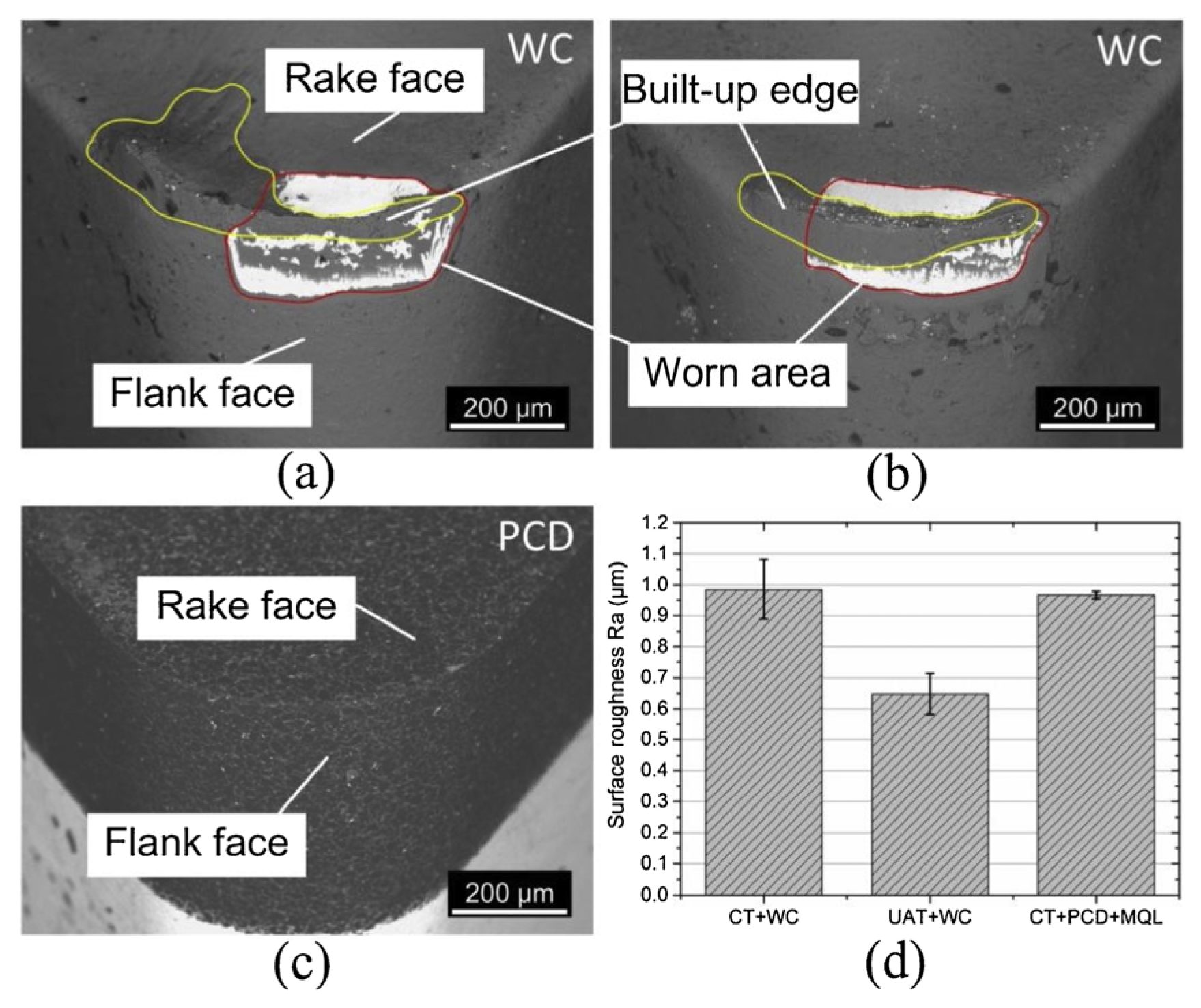
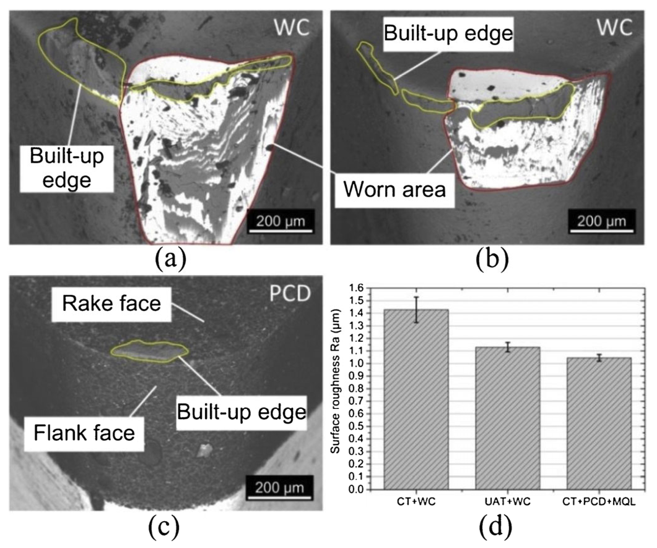
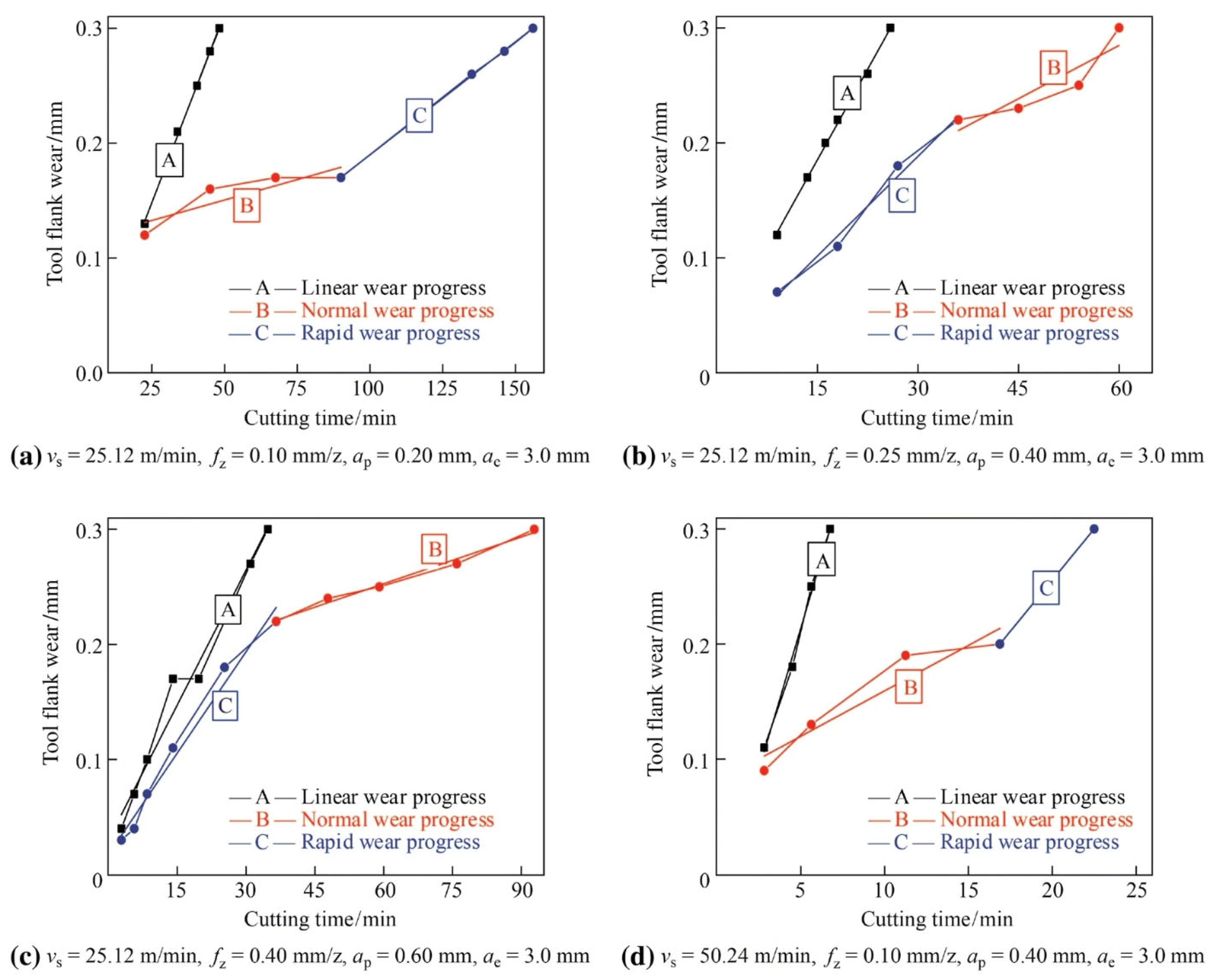
2. Tool Wear and Tool Life
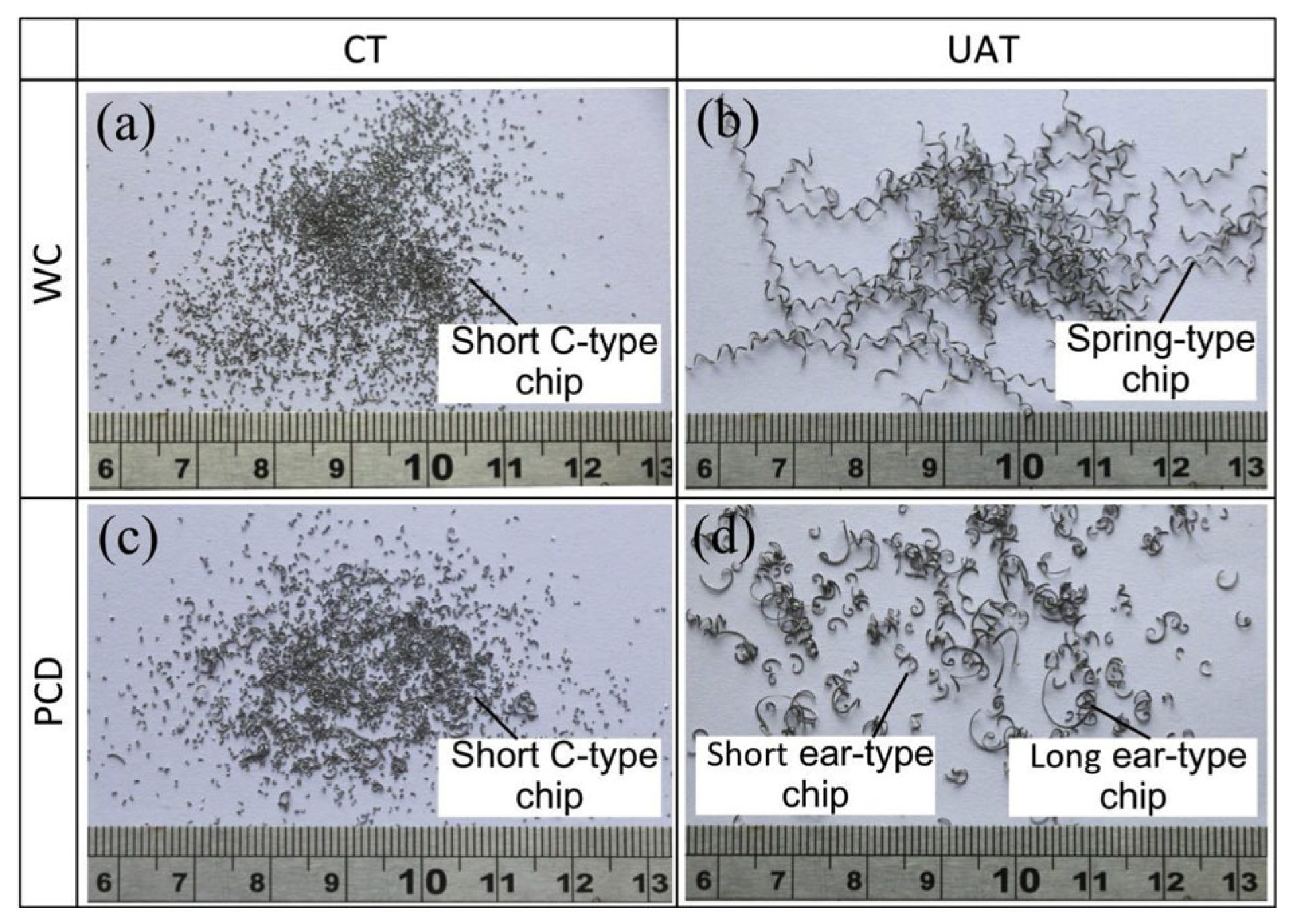
Al-based composite materials, characterized by a heterogeneous structure due to hard particles within a more ductile matrix, induce varying thermal and mechanical loads as the cutting edge traverses the different composite constituents. Additionally, ultrasonic vibration-assisted machining was applied, altering the contact between the cutting tool and the workpiece. These changes significantly influence tool wear. Generally speaking, a cutting tool is identified by the flank wear width of the cutting tool and the tool life. When the flank wear width of the cutting tool reaches 0.3 mm, the tool fails. The tool life refers to the time it takes for the flank wear width of the cutting tool to reach 0.3 mm [11,51]. When machining metal matrix composites, a variety of tools are deployed, depending on the volume fraction of the composites, such as PCD, PCBN, CVD diamond coating, CBN coating, and uncoated WC [52,53,54]. For machining Al-based metal matrix composites, several types of tools are commonly used, including a carbide insert, PCD, and TiAlN coating [55,56,57,58,59]. The research has found that severe tool wear occurs during the machining of aluminum-based metal matrix composites. However, the introduction of an ultrasonic energy field is beneficial for reducing tool wear and extending tool life. Bertolini et al. [60] investigated the effect of cutting parameters on tool wear by conducting both conventional turning and ultrasonic vibration-assisted turning. They found that tool wear was reduced by up to 51% compared to conventional turning. Additionally, as the feed rate increased, the tool wear decreased. And they observed that the tool wear increased by increasing the volume of the removed material for all the conventional turning cases, while in the ultrasonic vibration-assisted turning, the higher the cutting speed was, the more severe the tool wear was. The wear mechanism was mainly adhesion rather than abrasion, as shown in Figure 3. Dong et al. [61] discovered that the flank face wear was significantly reduced. The rake face wear was free from the crater during the ultrasonic vibration-assisted turning of SiCp/Al composites with PCD tools. This was because the ultrasonic vibration could cause intermittent contact between the PCD tool and the workpiece. Similarly, less damage and shorter cracks were observed on the flank face during the ultrasonic vibration-assisted cutting of SiCp/Al composites. In contrast, numerous damages, such as pits, micro-grooving, porosity, micro-chipping, and material adhesion, emerged on the tool flank during conventional cutting [62], as seen in Figure 4.
Bai et al. [63] carried out ultrasonic-assisted turning and conventional turning with the use of a cemented carbide (WC) and a polycrystalline diamond (PCD) tool. Abrasive and adhesive wear occurred on the WC tool in both methods. However, the machined surface obtained in the former with the WC tool was comparable and sometimes even superior to that achieved with the PCD tool, as shown in Figure 5 and Figure 6.
Pan et al. [64] discovered that the increase in drilling temperature could soften the SiCp/Al composites, reducing tool wear on the front face but increasing the material adhesion on the back face during the ultrasonic-assisted drilling of SiCp/Al composites. To elucidate the mechanism of tool wear, Hao et al. [65] developed a mathematical model of tool wear, taking into account the influence of cutting force and cutting yield strength on cutting temperature during the ultrasonic elliptical vibration-assisted cutting of SiCp/Al composites using a PCD tool. The optimal cutting temperature range for ultrasonic elliptical vibration in the low-speed cutting of aluminum silicon carbide is between 0 and 150 °C, and the temperature range for high-speed cutting is between 350 and 400 °C, resulting in minimal tool wear.
It is widely acknowledged that the TiB2/Al composite exhibits distinct differences from SiCp/Al composites, particularly in terms of preparation methods and properties. Despite the significantly smaller volume and size of the particles in the TiB2/Al composite, severe tool wear [66], elevated cutting forces and temperatures [67,68], surface damage, and large surface roughness [18,69] were observed during conventional machining processes. Consequently, ultrasonic vibration was employed to enhance machinability. Liu et al. [70] conducted an experimental study on tool wear during the ultrasonic vibration-assisted milling of in situ TiB2/7050Al composites, and the results are illustrated in Figure 7.
They found that in conventional cutting, the flank wear progressed rapidly and linearly. In contrast, ultrasonic vibration-assisted cutting exhibited both a normal wear stage and a rapid wear stage. Tool wear was significantly reduced, and tool life was extended by approximately two to five times.

3. Chip Formation

Bai et al. [63] found that short-segmented C-type chips were produced during conventional turning (CT), likely due to the reduction in ductility of the MMC material caused by the addition of SiC particles. Additionally, saw-tooth features on the free surface were observed, suggesting that an adiabatic shear process dominated chip formation. Fractures along the short C-type chip were observed on the back surface of the chip, as shown in Figure 8. In ultrasonic-assisted turning (UAT), continuous and semi-continuous chips with improved surface topography and lamellar structures were observed on the free surface, as illustrated in Figure 9. This may be attributed to the increased ductility of the workpiece material due to the high-frequency vibration. The periodic nature of tool–chip contact favored intermittent chip formation. Furthermore, it was discovered that the chip morphology was significantly influenced by the cutting parameters [60]. Obviously, under the two processing methods, with the increase in the feed rate, the length and ductility of the chips increase. Typically, short chips are highly preferred during machining operations because their formation not only averts chips from entangling around the workpiece and cutting tool but also safeguards the newly machined surface from potential damage. Short C-type chips were more readily produced with minimal feed rates during ultrasonic vibration-assisted turning than conventional turning, as illustrated in Figure 10.
Du et al. [71] investigated the chip formation of SiCp/Al during ultrasonic elliptical vibration cutting compared to conventional cutting. They found that the chips produced in conventional cutting were prone to breakage and exhibited a serrated morphology, with voids and microcracks observed. In contrast, ultrasonic elliptical vibration cutting resulted in continuous serrated chips with deeper serrations, and the cuts were more continuous, as shown in Figure 11.
Zhao et al. [72] found that the chip deformation of SiCp/Al was markedly different between conventional cutting (CC) and ultrasonic cutting (UC). The material experienced severe extrusion and deformation in CC, resulting in short chips with a smaller curl radius. Conversely, the high-frequency vibration in UC led to less deformation, producing small and loose chips with a larger curl radius, as shown in Figure 12.
Zhou et al. [62] found that the chips produced during conventional cutting were fragmented, with SiC particles broken and the Al matrix torn apart at the chip fracture. Numerous SiC particle crushings and microcracks were observed on the chip’s free surface. In contrast, after ultrasonic vibration-assisted cutting (UVAC), the free- surface ductility of the chips was enhanced, resulting in continuous chips with a layered structure, as shown in Figure 13.
Niu [73] investigated the influence of vibration amplitude on the cutting performance of 20% SiCp/Al composites during ultrasonic vibration-assisted milling. The results showed that as the amplitude increased, the chips transitioned from crimped to flake shaped, as illustrated in Figure 14. Defects on the non-free surfaces of chips shifted from fracture zones and material bonding to microcracks and particle bulges. In contrast, the plastic deformation of the chip was reduced, as illustrated in Figure 15. An amplitude below 5 μm did not enhance machinability. In contrast, when the amplitude increased to 3 μm, it significantly affected the cutting force, surface roughness, surface morphology, and chip formation.

4. Cutting Force and Temperature

Many studies have indicated that ultrasonic vibration can significantly reduce cutting force [74]. It was found that the cutting force was reduced by 26% and 23% at different cutting depths [71] and by approximately 40% [62]. Liu et al. [75] investigated the cutting force characteristics in the ultrasonic vibration-assisted turning (UVAT) of SiCp/Al composites with a vibration amplitude of 15 μm and a vibration frequency of 20 kHz, as shown in Figure 16. They discovered that ultrasonic vibration-assisted turning notably decreased the average cutting force Fc. However, when considering the influence of rotational speed (n), the variation trend of the average cutting force differed between conventional and ultrasonic vibration-assisted turning. In conventional turning, the average cutting force Fc remained relatively constant. In contrast, during ultrasonic vibration-assisted turning, Fc increased steadily as the rotational speed rose. There could be two possible reasons for this phenomenon. First, built-up edge formation in conventional cutting might reduce the cutting force. Second, as the rotating speed rises, the ultrasonic vibration’s effectiveness may be compromised, causing the cutting process to approximate conventional cutting, thus leading to a divergence in the cutting force trends of the two methods.
Dong et al. [76] verified that the ultrasonic vibration-assisted grinding (UVAG) of SiCp/Al composites led to a significant reduction in grinding force, with reductions ranging from 35% to 50%, as shown in Figure 17. Furthermore, Bie et al. [77] developed theoretical models for both normal and tangential cutting forces, considering the ductile region, ductile-to-brittle transition region, and brittle region to elucidate the material removal mechanisms during the longitudinal–torsional vibration end surface grinding of SiCf/SiC composites.
Bai et al. [63] found that ultrasonic vibration significantly reduced cutting force. The experimental results indicated that the force reductions were 68%, 66%, and 25% for cutting, thrust, and feed forces, respectively, for the WC tool under dry machining conditions, as shown in Figure 18. Moreover, the cutting temperature in ultrasonic vibration turning (UVT) was higher than in conventional turning (CT), which may be attributed to the additional energy introduced by the vibrating tool, as shown in Figure 19. However, it was noted that the temperature during ultrasonic milling was significantly lower than that of traditional milling, and the milling temperature decreased with an increase in amplitude [78], as illustrated in Figure 20. This phenomenon can be ascribed to a decreased likelihood of clogging as the ultrasonic amplitude increased, facilitating chip removal and reducing temperature accumulation.
Niu et al. [79] noted that longitudinal–torsional ultrasonic vibration-assisted milling (LTUVAM) could effectively reduce the cutting force and cutting heat and improve the surface quality of the workpiece compared to conventional milling, as shown in Figure 21 and Figure 22. However, it was necessary to match the appropriate ultrasonic amplitude and cutting speed. Shi et al. [80] found that ultrasonic vibration was conducive to softening SiCp/Al composites and maintaining the integrity of carbide particles, thereby reducing milling force and surface roughness. Peng et al. [81] investigated the material removal characteristics during the axial ultrasonic vibration grinding of SiCp/Al composites using a single diamond grain. They found that ultrasonic vibration significantly decreased the grinding force, as shown in Figure 23. They concluded that ultrasonic vibration could effectively separate the abrasive grain from the workpiece, facilitate the timely cutting and discharge of plastic Al metal abrasive chips, and induce the micro-fragmentation of SiC particles.
To elucidate the sources and variations in the cutting force during the ultrasonic vibration-assisted machining of SiCp/Al, Liu [82] developed a comprehensive ultrasonic vibration-assisted scratching force model that incorporates the forces associated with chip formation, SiC particle fracture, tool–Al matrix friction, and rolling friction. Experimental validation confirmed a consistent overall trend between theoretical predictions and empirical results, thereby substantiating the feasibility of the scratching force model. Lin et al. [83] developed a predictive model for the cutting force in the ultrasonic vibration-assisted turning of SiCp/Al, incorporating the instantaneous depth of cut and the shear angle. The predicted main cutting force was validated against experimental results, demonstrating an error margin of less than 13%. Yang et al. [84] developed a force model to predict the drilling force for the ultrasonic vibration drilling of micro-holes in high-volume fraction SiCp/Al composites, accounting for the effects of ultrasonic vibration and undeformed cutting thickness. The model was validated through simulation and experimentation, demonstrating high accuracy. Li et al. [85] developed a mechanical cutting force model for the ultrasonic vibration-assisted helical grinding of SiCp/Al. The model comprised three components: frictional force, plastic deformation force, and fracture force. The model accounted for the effects of the undeformed chip thickness and cross-sectional area while incorporating an ultrasonic softening coefficient to quantify the reduction in deformation stress due to ultrasonic vibration. The theoretical model was validated by experimental results, demonstrating a deviation of only 5.07%.
Regarding the TiB2/Al composite, Liu et al. [86] developed an instantaneous cutting force model for ultrasonic vibration-assisted milling, incorporating the influence of ultrasonic vibration. It was revealed that the chip could achieve acceleration induced by ultrasonic vibration, altering the composition of cutting forces, as shown in Figure 24. Additionally, the analytical results were validated by experiments, demonstrating a relative error of less than 10%. Meanwhile, they found that the cutting force could be reduced in ultrasonic vibration-assisted milling, but the extent of reduction is subject to the impact of cutting parameters; within the experimental framework he established, the maximum reduction in cutting force reached 31.8%.
It can be seen from the above that the introduction of ultrasonic energy would have a significant impact on the cutting force, which in turn would cause changes in the cutting temperature. Especially in machining, the temperature of the workpiece would have an important influence on the cutting residual stress and the integrity of the cutting surface. At present, the research on the cutting temperature of particle-reinforced aluminum matrix composites mainly focuses on cutting experiments, finite element simulation, and theoretical modeling analysis [87].
Jayakumar et al. [88] conducted milling experiments on SiCp/Al composites with different particle volume fractions. An infrared thermal imager was used to measure the cutting temperature, and the variation law of the cutting temperature at the tool–workpiece contact surface was studied. The results showed that the content of the SiC particles and the cutting speed had the greatest influence on the cutting temperature. In order to have an in-depth study, Liu and Chou [89,90] carried out a comparative experimental and simulation study on the cutting temperature of SiCp/Al composites. The results showed that the cutting speed was the main factor affecting the cutting temperature, and the established cutting temperature simulation model could predict the cutting temperature relatively accurately. Moreover, to reveal the mechanism of the generation of cutting heat, Zhu and Kishawy [91] conducted a simulation study on the cutting temperature of SiCp/Al composites based on the Abaqus finite element software, version 6.2. It was found that, similar to traditional metal cutting, there were mainly three heat sources in the second deformation zone during the cutting of SiCp/Al composites, namely the heat source from the plastic deformation of the chip, the heat source from the tool–chip friction, and the heat source from the chip sliding. Among them, the tool–chip friction was the main factor contributing to the generation of cutting heat, while the plastic deformation was the main factor for the generation of heat in the first deformation zone. Furthermore, Xiong et al. [67] established an analytical cutting–temperature model for in situ TiB2/7050Al metal matrix composites during end milling. The model was proven by the experimental value measured with a semi-artificial thermocouple, as shown in Figure 25, and the relative error of the model was less than 18%. Similarly, Liu et al. [92] established an analytical workpiece temperature model for the ultrasonic vibration-assisted milling of in situ TiB2/Al metal matrix composites. The model was validated through milling experiments with and without ultrasonic vibration with relative errors of less than 17%. It was found that the subsurface temperature field of the workpiece was distributed behind the cutting edge, and by increasing the depth below the machined surface, the high-temperature region moved far away from the cutting tool nose, as shown in Figure 26. Peng et al. [93] established a cutting temperature prediction model that comprehensively takes into account the influences of material heterogeneity, the thermal effect of the laser, and ultrasonic elliptical vibration. The research shows that the highest temperature in the cutting layer is located in the contact area between the tool tip and the chip. The maximum deviation between the model prediction and the experimental results is 17.1%. The laser heat source increases the cutting temperature, as shown in Figure 27. Moreover, selecting an appropriate vibration amplitude can effectively reduce the temperature and processing damage.
In conclusion, in-depth studies on cutting force and cutting temperature are of great significance for the research on surface integrity, such as cutting residual stress, machining surface quality, machining hardness, and surface defects.

5. Surface Integrity

In the study [71], surface damages such as voids and grooves were observed in the conventional cutting of SiCp/Al, whereas the machined surface was smooth in ultrasonic elliptical vibration cutting. The surface roughness was reduced; the values of Ra, Sq, and Rz were reduced by 19% and 28%, 40% and 43%, and 50% and 64% at the cutting depths of 25 mm and 50 mm, respectively. At a cutting depth of 50 mm, the TC caused more particles to be pulled out and form cavities clustered together, resulting in poor surface integrity and affecting surface roughness. According to Zhou et al. [62], the surface damage in ultrasonic vibration-assisted cutting (UVAC) primarily consisted of small holes, minimal particle debonding, fractures, and detachment. In contrast, the conventional cutting (CC) surface exhibited numerous holes, significant particle debonding, and fractures, as shown in Figure 28. The surface roughness Sa was reduced by 34%, and the depth of subsurface damage was decreased by 86% with ultrasonic vibration. The improvement in the machined surface may be attributed to the fact that ultrasonic vibration facilitates the secondary processing of unbroken particles on the machined surface [94]. It is possible that the volume and size of the particles differed from those in the SiCp/Al composites. During the ultrasonic vibration-assisted milling of the TiB2/Al composite [95], no particle debonding or cracks were observed; instead, regularly distributed micro-dimples were present on the machined surface, as shown in Figure 29. Liu et al. [96] conducted an experimental investigation into the surface integrity of the in situ TiB2/Al composite through both conventional cutting and ultrasonic vibration-assisted cutting. The results demonstrated that lower surface roughness and higher surface compressive stress could be achieved by optimizing the cutting and ultrasonic vibration parameters.
Zhao et al. [72] discovered that surface defects, such as burrs and built-up edges, etc., were fewer in the UVAT process, and the cutting process was more stable. Moreover, the tangential residual compression stress of UC was greater than that of CC, which is shown in Figure 30. However, Chen and Zhang [94] found that the residual stress on the machined surface of ultrasonic elliptical vibration cutting (UEVC) was significantly lower than that of orthogonal cutting (OC), decreasing to between one-quarter and one-seventh of the stress observed in OC through simulation. Unlike the continuous contact of chips in orthogonal cutting (OC), during most of a single cycle, the tool and the chip were separated in ultrasonic elliptical vibration cutting (UEVC), preventing any extrusion between them. To reveal the mechanism behind the increase in residual compressive stress, Liu et al. [97] developed a theoretical model to predict the residual stress, taking into account the cutting force and cutting temperature. The predicted results were validated by experimental data, with the relative error remaining below 20%. It was found that cutting parameters played a critical role in the mechanical–thermal coupling effect, influencing the residual stress.
Xiang et al. [98] investigated the formation mechanism of edge defects in the longitudinal–torsional ultrasonic vibration-assisted milling (LTUAM) of SiCp/Al composites using both simulation and experimental methods. The particles were fragmented into smaller sizes and more easily removed, leading to reduced particle accumulation and improved surface quality in ultrasonic vibration-assisted machining. Furthermore, the results indicated that the application of ultrasonic vibration could enhance the surface and edge quality of SiCp/Al composites. A similar conclusion was drawn in [99]. Additionally, Peng et al. [100] explained that ultrasonic vibration could enhance material plastic flow and reduce the length of burrs and cracks, as shown in Figure 31.
The superior performance of ultrasonic-assisted machining has prompted researchers to investigate the fundamental mechanisms involved in this process. The scratch test using a single diamond grit is one of the most common methods for studying material removal mechanisms. To analyze the material deformation and removal mechanisms of SiCp/Al composites, Feng et al. [101] elaborated that ultrasonic vibration-assisted scratch tests improved the surface quality of SiCp/Al. Under high-frequency ultrasonic vibration, large particles were broken into smaller chips, and the material removal underwent plastic deformation. In contrast, severe surface damage and uneven grooves were observed on the conventionally machined surface, as shown in Figure 32. Similar conclusions were also reported in [102].
Li et al. [103] conducted rotary ultrasonic vibration-assisted scratch (RUVAS) tests and conventional scratch (CS) tests to investigate the machining mechanism. The results are shown in Figure 33 and Figure 34. With the assistance of ultrasonic vibration, plastic deformation occurred in SiCp/Al. The hard SiC particles were fractured and embedded into the plastic matrix, effectively suppressing the initiation and propagation of cracks, reducing the stress influence zone, decreasing surface defects, and enhancing surface integrity. Subsurface damage, including particle cracking, matrix tearing, and interface failure, occurred in both conventional scratch (CS) and rotary ultrasonic vibration-assisted scratch (RUVAS). However, the depth and extent of subsurface damage were smaller in RUVAS. Furthermore, it was indicated that the state of the particles significantly influenced surface integrity.
Zheng et al. [104] pointed out that the relative positions of the cutting tool and SiC particles could lead to different removal modes, including rolling or penetration within the Al matrix, partial or complete fracturing, and pull out. Significant damage occurred to the SiC particles and their surrounding interfaces in both the complete fracturing and pull-out modes. Moreover, Wang et al. [105] discovered that groove and pit defects were more prevalent in the continuous contact mode between the tool and the workpiece. At the same time, voids and particle fractures typically arose in the intermittent contact mode, as indicated by the simulation results. Consequently, a smaller cutting depth was recommended to ensure better structural integrity of SiCp/Al composites during the actual machining process [104].
Yan et al. [106] investigated the influence of ultrasonic vibration on the multiscale deformation of SiCp/Al composites through molecular dynamics simulations (MD) and ultrasonic vibration indentation tests. The findings indicated that ultrasonic high-frequency energy could accelerate interfacial failure and the fragmentation of SiC particles, contribute to grain refinement, as shown in Figure 35, and promote the brittle-to-plastic transition during the deformation of SiCp/Al composites, thereby significantly enhancing the surface processing quality of the material. Gao et al. [107] investigated the ductile–brittle transition mechanism of SiC particles by conducting tests comparing ultrasonic vibration-assisted grinding and conventional grinding with single grains. The findings demonstrated that ultrasonic vibration increased the critical depth of the ductile–brittle transition in SiC particles, thereby facilitating micro-brittle fracture and significantly reducing both surface and subsurface damage in SiCp/Al composites, as shown in Figure 36. Peng et al. [81] also reached similar conclusions.

6. Conclusions

This paper comprehensively reviews ultrasonic vibration-assisted machining technology applied to particle-reinforced Al-based matrix composites, focusing on two representative materials: TiB2/Al and SiCp/Al. This study highlights key research findings on tool wear, chip morphology, cutting forces, cutting temperatures, and surface integrity during ultrasonic vibration-assisted machining. Based on these findings, the following principal conclusions are drawn:
(1)
Ultrasonic vibration-assisted machining effectively mitigates frictional forces and contact stresses during the cutting process by periodically altering the contact state between the tool and the workpiece, thereby significantly reducing tool wear rates and extending tool life. Additionally, ultrasonic vibrations facilitate chip fracture and ejection, resulting in finer and more uniform chip morphology, which reduces the formation of long or spiral chips and minimizes the risk of chip entanglement and blockage, thus enhancing the continuity and stability of the machining process.
(2)
The periodic separation and elastic recovery of the material induced by ultrasonic vibrations lead to a reduction in both the average and peak cutting forces, decreasing the load on the machine tool and improving machining precision and efficiency. The reduction in cutting forces, coupled with efficient chip removal, facilitates faster heat dissipation, preventing localized overheating in the cutting zone and maintaining the quality of the machined workpiece.
(3)
Ultrasonic vibration-assisted machining significantly diminishes residual stresses, microcracks, and surface roughness on the machined surface, thereby enhancing surface quality. This is particularly important for particle-reinforced Al-based matrix composites, which are highly sensitive to surface defects, as ultrasonic vibration technology represents a critical approach for achieving high-quality machining.
However, limited research has been conducted on the impact of ultrasonic vibration energy on the material properties, necessitating further in-depth exploration. Currently, we are conducting both experimental and theoretical studies on the softening effect, thermal effect, and stress superposition in particle-reinforced Al-based matrix composites.

Author Contributions

Conceptualization, X.L.; Funding acquisition, X.L. and Q.Y.; Investigation, X.L.; Methodology, X.L. and Y.X.; Writing—original draft, X.L.; Writing—review & editing, X.L., Y.X. and Q.Y. All authors have read and agreed to the published version of the manuscript.

Funding

This work is sponsored by the Natural Science Basic Research Program of Shaanxi (Grant No. 2023-JC-QN-0527), the College Students’ Innovative Entrepreneurial Training Plan Program (Grant No. 202411396006), the Research Fund of Key Laboratory of High Performance Manufacturing for Aero Engine (Northwestern Polytechnical University), Ministry of Industry and Information Technology (Grant No. HPM-2022-02), Natural Science Basic Research Program of ShangLuo University (Grant No. 22SKY105), the Youth Innovation Team of Shaanxi Universities.

Data Availability Statement

All authors confirm that the data supporting the findings of this study are available within the article.

Acknowledgments

Many thanks to the support of the ultrasonic vibration equipment from Xi’an Chao Ke Neng Ultrasonic Technology Research Institute Co., Ltd.

Conflicts of Interest

The authors declare that they have no conflicts of interest.

References

  1. Ma, L.; Zhou, C.Z.; Wen, Q.; Li, M.S.; Zhong, H.; Ji, S.D. Ultrasonic-promoted rapid transient liquid phase bonding of high volume fraction SiC particle reinforced aluminum-based metal matrix composite in low temperature. Ultrasonics 2020, 106, 106159. [Google Scholar] [CrossRef] [PubMed]
  2. Beffort, O.; Long, S.Y.; Cayron, C.; Kuebler, J.; Buffat, P.A. Alloying effects on microstructure and mechanical properties of high volume fraction SiC-particle reinforced Al-MMCs made by squeeze casting infiltration. Compos. Sci. Technol. 2007, 67, 737–745. [Google Scholar] [CrossRef]
  3. Liang, Y.N.; Ma, Z.Y.; Li, S.Z.; Li, S.; Bi, J. Effect of particle-size on wear behavior of SiC particulate-reinforced aluminum-alloy composites. J. Mater. Sci. Lett. 1995, 14, 114–116. [Google Scholar] [CrossRef]
  4. Shen, X.Y.; Ren, S.; He, X.B.; Qin, M.L.; Qu, X.H. Study on methods to strengthen SiC performs for SiCp/Al composites by pressureless infiltration. J. Alloys Compd. 2009, 468, 158–163. [Google Scholar] [CrossRef]
  5. Liu, Z.Y.; Wang, Q.Z.; Xiao, B.L.; Ma, Z.Y.; Liu, Y. Experimental and modeling investigation on SiCp distribution in powder metallurgy processed SiCp/2024 Al composites. Mater. Sci. Eng. A 2010, 527, 5582–5591. [Google Scholar] [CrossRef]
  6. Ahmad, Z. Mechanical behavior and fabrication characteristics of aluminum metal matrix composite alloys. J. Reinf. Plast. Compos. 2001, 20, 921–944. [Google Scholar] [CrossRef]
  7. Ghasali, E.; Pakseresht, A.H.; Alizadeh, M.; Shirvanimoghaddam, K.; Ebadzadeh, T. Vanadium carbide reinforced aluminum matrix composite prepared by conventional, microwave and spark plasma sintering. J. Alloys Compd. 2016, 688, 527–533. [Google Scholar] [CrossRef]
  8. Xiong, F.; Wang, W.H.; Shi, Y.Y.; Jiang, R.S.; Lin, K.Y.; Song, G.D.; Shao, M.; Liu, X.F.; Li, J.C.; Shan, C.W. Machining performance of in-situ TiB2 particle reinforced Al-based metal matrix composites: A literature review. J. Adv. Manuf. Sci. Technol. 2021, 1, 2021003. [Google Scholar]
  9. Liu, Q.; Wang, F.; Qiu, X.; An, D.; He, Z.Y.; Zhang, Q.F.; Xie, Z.P. Effects of La and Ce on microstructure and properties of SiC/Al composites. Ceram. Int. 2019, 46, 1232–1235. [Google Scholar] [CrossRef]
  10. Liu, Q.Y.; Wang, F.; Shen, W.; Qiu, X.P.; He, Z.Y.; Zhang, Q.F.; Xie, Z.P. Influence of interface thermal resistance on thermal conductivity of SiC/Al composites. Ceram. Int. 2019, 45, 23815–23819. [Google Scholar] [CrossRef]
  11. Xiong, Y.F.; Wang, W.H.; Jiang, R.S.; Lin, K.Y.; Song, G.D. Tool wear mechanisms for milling in situ TiB2 particle-reinforced Al matrix composites. Int. J. Adv. Manuf. Technol. 2016, 86, 3517–3526. [Google Scholar] [CrossRef]
  12. Lin, K.Y.; Wang, W.H.; Jiang, R.S.; Xiong, Y.F. Effect of tool nose radius and tool wear on residual stresses distribution while turning in situ TiB2/7050 Al metal matrix composites. Int. J. Adv. Manuf. Technol. 2019, 100, 143–151. [Google Scholar] [CrossRef]
  13. Shin, S.; Cho, S.; Lee, D.; Kim, Y.; Lee, S.B.; Lee, S.K.; Jo, I. Microstructural Evolution and Strengthening Mechanism of SiC/Al Composites Fabricated by a Liquid-Pressing Process and Heat Treatment. Materials 2019, 12, 3374. [Google Scholar] [CrossRef] [PubMed]
  14. Li, X.P.; Seah, W.K.H. Tool wear acceleration in relation to workpiece reinforcement percentage in cutting of metal matrix composites. Wear 2001, 247, 161–171. [Google Scholar] [CrossRef]
  15. Ozben, T.; Kilickap, E.; Cakir, O. Investigation of mechanical and machinability properties of SiC particle reinforced Al-MMC. J. Mater. Process. Technol. 2008, 198, 220–225. [Google Scholar] [CrossRef]
  16. Ciftci, I.; Turker, M.; Seker, U. Evaluation of tool wear when machining SiCp-reinforced Al-2014 alloy matrix composites. Mater. Des. 2004, 25, 251–255. [Google Scholar] [CrossRef]
  17. Pugazhenthi, A.; Kanagaraj, G.; Dinaharan, I.; Selvam, J.D.R. Turning characteristics of in situ formed TiB2 ceramic particulate reinforced AA7075 aluminum matrix composites using polycrystalline diamond cutting tool. Measurement 2018, 121, 39–46. [Google Scholar] [CrossRef]
  18. Jiang, R.S.; Wang, W.H.; Song, G.D.; Wang, Z.Q. Experimental investigation on machinability of in situ formed TiB2 particles reinforced Al MMCs. J. Manuf. Process. 2016, 23, 249–257. [Google Scholar]
  19. Manna, A.; Bhattacharayya, B. Influence of machining parameters on the machinability of particulate reinforced Al/SiC-MMC. Int. J. Adv. Manuf. Technol. 2005, 25, 850–856. [Google Scholar] [CrossRef]
  20. Nikouei, S.M.; Kouchakzadeh, M.A.; Yousefi, R.; Kadivar, M.A. Investigation of cutting model in machining of Al/SiCp metal matrix composite. Appl. Mech. Mater. 2012, 117, 1465–1470. [Google Scholar]
  21. Pramanik, A.; Zhang, L.C.; Arsecularatne, J.A. Prediction of cutting forces in machining of metal matrix composites. Int. J. Mach. Tools Manuf. 2006, 46, 1795–1803. [Google Scholar] [CrossRef]
  22. Xiong, Y.F.; Wang, W.H.; Jiang, R.S.; Lin, K.Y. A study on cutting force of machining in situ TiB2 particle-reinforced 7050Al alloy matrix composites. Metals 2017, 7, 197. [Google Scholar] [CrossRef]
  23. Chen, J.P.; Gu, L.; He, G.J. A review on conventional and nonconventional machining of SiC particle-reinforced aluminium matrix composites. Adv. Manuf. 2020, 8, 279–315. [Google Scholar] [CrossRef]
  24. Pugazhenthi, A.; Dinaharan, I.; Kanagaraj, G.; Selvam, J.D.R. Predicting the effect of machining parameters on turning characteristics of AA7075/TiB2 in situ aluminum matrix composites using empirical relationships. J. Braz. Soc. Mech. Sci. Eng. 2018, 40, 555. [Google Scholar] [CrossRef]
  25. Anandakrishnan, V.; Mahamani, A. Investigations of flank wear, cutting force, and surface roughness in the machining of Al-6061-TiB2 in situ metal matrix composites produced by flux-assisted synthesis. Int. J. Adv. Manuf. Technol. 2011, 55, 65–73. [Google Scholar] [CrossRef]
  26. Mahamani, A. Influence of process parameters on cutting force and surface roughness during turning of AA2219-TiB2/ZrB2 in-situ metal matrix composites. Procedia Mater. Sci. 2014, 6, 1178–1186. [Google Scholar] [CrossRef]
  27. Ghinattia, E.; Bertolini, R.; Sorgato, M.; Ghiotti, A.; Bruschi, S. Tool wear and surface finish analysis after drilling Al-SiC metal matrix composite with DLC-coated tools at varying feed. In Proceedings of the 7th CIRP Conference on Surface Integrity, Procedia CIRP, Bremen, Germany, 15–17 May 2024; Volume 123, pp. 53–58. [Google Scholar]
  28. Jin, P.; Gao, Q.; Wang, Q.; Wang, Q.Z.; Guo, G.Y. Study on the surface quality of 60vol% SiCp/Al2024 composites with large-grained. Proc. Inst. Mech. Eng. Part C-J. Mech. Eng. Sci. 2022, 236, 5391–5411. [Google Scholar] [CrossRef]
  29. Gallab, M.E.; Sklad, M. Machining of Al/SiC particulate metal matrix composites part II Workpiece surface integrity. J. Mater. Process. Technol. 1998, 83, 277–285. [Google Scholar] [CrossRef]
  30. Zhao, X.; Gong, Y.D.; Liang, G.Q.; Cai, M.; Han, B. Face Grinding Surface Quality of High Volume Fraction SiCp/Al Composite Materials. Chin. J. Mech. Eng. 2021, 34, 3. [Google Scholar] [CrossRef]
  31. Xiong, Y.F.; Wang, W.H.; Jiang, R.S.; Lin, K.Y.; Song, G.D. Surface integrity of milling in-situ TiB2 particle reinforced Al matrix composites. Int. J. Refract. Met. Hard Mater. 2016, 54, 407–416. [Google Scholar] [CrossRef]
  32. Bao, Y.J.; Zhu, X.C.; Lu, S.X.; Zhang, H.Z. Research Progress of Low Damage Machining Technology for SiCp/Al Composites. Rare Met. Mater. Eng. 2021, 50, 1084–1095. [Google Scholar]
  33. Azarhoushang, B.; Tawakoli, T. Development of a novel ultrasonic unit for grinding of ceramic matrix composites. Int. J. Adv. Manuf. Technol. 2011, 57, 945–955. [Google Scholar] [CrossRef]
  34. Brehl, D.E.; Dow, T.A. Review of vibration-assisted machining. Precis. Eng. 2008, 32, 153–172. [Google Scholar] [CrossRef]
  35. Yang, Z.C.; Zhu, L.D.; Zhang, G.X.; Zhang, G.X.; Ni, C.B.; Lin, B. Review of ultrasonic vibration-assisted machining in advanced materials. Int. J. Mach. Tools Manuf. 2020, 156, 103594. [Google Scholar] [CrossRef]
  36. Zhang, C.M. Study on the cutting force in elliptical ultrasonic vibration cutting. Adv. Intell. Syst. Comput. 2019, 885, 1137–1142. [Google Scholar]
  37. Ramón, J.-M. Microtexturing of industrial surfaces via radial ultrasonic vibration-assisted machining: An analytical model and experimental validation. Surf. Coat. Technol. 2024, 482, 130718. [Google Scholar]
  38. Jiang, X.D.; Xiao, D.H.; Teng, X.Y. Influence of vibration parameters on ultrasonic vibration cutting micro-particles reinforced SiC/Al metal matrix composites. Int. J. Adv. Manuf. Technol. 2022, 119, 6057–6071. [Google Scholar] [CrossRef]
  39. Zhou, M.; Wang, M.; Dong, G.J. Experimental investigation on rotary ultrasonic face grinding of SiC/Al composites. Mater. Manuf. Process. 2016, 31, 673–678. [Google Scholar] [CrossRef]
  40. Duan, J.W.; Zou, P.; Wang, A.Q.; Wei, S.Y.; Fang, R. Research on three-dimensional ultrasonic vibration-assisted turning cutting force. J. Manuf. Process. 2023, 91, 167–187. [Google Scholar] [CrossRef]
  41. Zhou, M.; Eow, Y.T.; Ngoi, B.K.A.; Lim, E.N. Vibration assisted precision machining of steel with PCD tools. Mater. Manuf. Process. 2003, 18, 825–834. [Google Scholar] [CrossRef]
  42. Nath, C.; Rahman, M. Effect of machining parameters in ultrasonic vibration cutting. Int. J. Mach. Tools Manuf. 2008, 48, 965–974. [Google Scholar] [CrossRef]
  43. Nath, C.; Rahman, M.; Neo, K.S. Machinability study of tungsten carbide using PCD tools under ultrasonic elliptical vibration cutting. Int. J. Mach. Tools Manuf. 2009, 49, 1089–1095. [Google Scholar] [CrossRef]
  44. Zhong, Z.W.; Lin, G. Ultrasonic vibration turning of an aluminium-based metal matrix composite reinforced with SiC particles. Int. J. Adv. Manuf. Technol. 2006, 27, 1077–1081. [Google Scholar] [CrossRef]
  45. Zhang, Z.W.; Lin, G. Diamond turning of a metal matrix composite with ultrasonic vibrations. Mater. Manuf. Process. 2005, 20, 727–735. [Google Scholar] [CrossRef]
  46. Wang, D.P.; Fan, H.J.; Xu, D.; Zhang, Y.L. Research on Grinding Force of Ultrasonic Vibration-Assisted Grinding of C/SiC Composite Materials. Appl. Sci. 2022, 12, 10352. [Google Scholar] [CrossRef]
  47. Zhang, Y.Q.; Hu, Z.W.; Chen, Y.; Yu, Y.Q.; Jin, J.F.; Peng, Q.; Xu, X.P. Insights into scratching force in axial ultrasonic vibration-assisted single grain scratching. J. Manuf. Process. 2024, 112, 150–160. [Google Scholar] [CrossRef]
  48. Zhou, W.H.; Tang, J.Y.; Chen, H.F.; Shao, W. A comprehensive investigation of surface generation and material removal characteristics in ultrasonic vibration assisted grinding. Int. J. Mech. Sci. 2019, 156, 14–30. [Google Scholar] [CrossRef]
  49. Wang, Y.; Guangheng, D.Y.; Zhao, J.N.; Dong, Y.H.; Zhang, X.F.; Jiang, X.M.; Lin, B. Study on key factors influencing the surface generation in rotary ultrasonic grinding for hard and brittle materials. J. Manuf. Process. 2019, 38, 549–555. [Google Scholar] [CrossRef]
  50. Shen, J.Y.; Wang, J.Q.; Jiang, B.; Xu, X.P. Study on wear of diamond wheel in ultrasonic vibration-assisted grinding ceramic. Wear 2015, 332, 788–793. [Google Scholar] [CrossRef]
  51. Rathod, B.S.; Pandey, B. Effect of turning parameters on aluminium metal matrix composites-a review. IOP Conf. Ser. Mater. Sci. Eng. 2017, 225, 012276. [Google Scholar] [CrossRef]
  52. Muguthu, J.N.; Dong, G.; Ikua, B.W. Optimization of machining parameters influencing machinability of Al2124SiCp (45%wt) metal matrix composite. J. Compos. Mater. 2015, 49, 217–229. [Google Scholar] [CrossRef]
  53. Njuguna, M.J.; Gao, D.; Hao, Z. Tool wear, surface integrity and dimensional accuracy in turning Al2124SiCp (45%wt) metal matrix composite using CBN and PCD tools. Res. J. Appl. Sci. Eng. Technol. 2013, 6, 4138–4144. [Google Scholar] [CrossRef]
  54. Laghari, R.A.; Jamil, M.; Laghari, A.A.; Khan, A.M.; Akhtar, S.S.; Mekid, S. A critical review on tool wear mechanism and surface integrity aspects of SiCp/Al MMCs during turning Prospects and challenges. Int. J. Adv. Manuf. Technol. 2023, 126, 2825–2862. [Google Scholar] [CrossRef]
  55. Laghari, R.A.; Li, J.; Xie, Z.; Wang, S.Q. Modeling and optimization of tool wear and surface roughness in turning of Al/SiCp using response surface methodology. 3D Res. 2018, 9, 46. [Google Scholar] [CrossRef]
  56. Laghari, R.A.; Li, J.; Wu, Y. Study of machining process of SiCp/Al particle reinforced metal matrix composite using finite element analysis and experimental verification. Materials 2020, 13, 5524. [Google Scholar] [CrossRef]
  57. Laghari, R.A.; Li, J.G.; Mia, M. Effects of turning parameters and parametric optimization of the cutting forces in machining SiCp/Al 45 wt% composite. Metals 2020, 10, 840. [Google Scholar] [CrossRef]
  58. Laghari, R.A.; Gupta, M.K.; Li, J.G. Evolutionary algorithm for the prediction and optimization of SiCp/Al metal matrix composite machining. J. Prod. Syst. Manuf. Sci. 2020, 2, 59–69. [Google Scholar]
  59. Laghari, R.A.; Li, J. Modeling and optimization of cutting forces and effect of turning parameters on SiCp/Al 45% vs SiCp/ Al 50% metal matrix composites A comparative study. SN Appl. Sci. 2021, 3, 706. [Google Scholar] [CrossRef]
  60. Bertolini, R.; Andrea, G.; Alagan, N.T.; Bruschi, S. Tool wear reduction in ultrasonic vibration-assisted turning of SiC-reinforced metal-matrix composite. Wear 2023, 523, 204785. [Google Scholar] [CrossRef]
  61. Dong, G.J.; Zhang, H.J.; Zhou, M.; Zhang, Y.J. Experimental investigation on ultrasonic vibration-assisted turning of SiCp/Al composites. Mater. Manuf. Process. 2013, 28, 999–1002. [Google Scholar] [CrossRef]
  62. Zhou, Y.; Gu, Y.; Lin, J.Q.; Zhao, H.B.; Liu, S.Y.; Xu, Z.S.; Yu, H.; Fu, X.B. Finite element analysis and experimental study on the cutting mechanism of SiCp/Al composites by ultrasonic vibration-assisted cutting. Ceram. Int. 2022, 48, 35406–35421. [Google Scholar] [CrossRef]
  63. Bai, W.; Roy, A.; Sun, R.L.; Silberschmidt, V.V. Enhanced machinability of SiC-reinforced metal-matrix composite with hybrid turning. J. Mater. Process. Technol. 2019, 268, 149–161. [Google Scholar] [CrossRef]
  64. Pan, X.; Chen, T.; Liu, F.; Zhang, C. Investigation of ultrasonic-assisted drilling temperature of SiCp/Al composites. Mater. Manuf. Process. 2024, 39, 1910–1918. [Google Scholar] [CrossRef]
  65. Hao, Z.P.; Zhang, H.H.; Fan, Y.H. Tool wear mathematical model of PCD during ultrasonic elliptic vibration cutting SiCp/Al composite. Int. J. Refract. Met. Hard Mater. 2025, 126, 106967. [Google Scholar] [CrossRef]
  66. Xiong, Y.F.; Wang, W.H.; Jiang, R.S.; Lin, K.Y. Machinability of in situ TiB2 particle reinforced 7050Al matrix composites with TiAlN coating tool. Int. J. Adv. Manuf. Technol. 2018, 97, 3813–3825. [Google Scholar] [CrossRef]
  67. Xiong, Y.F.; Wang, W.H.; Jiang, R.S.; Lin, K.Y. Analytical model of workpiece temperature in end milling in-situ TiB2/7050Al metal matrix composites. Int. J. Mech. Sci. 2018, 149, 285–297. [Google Scholar] [CrossRef]
  68. Jiang, R.S.; Chen, X.F.; GE, R.; Wang, W.H.; Song, G.D. Influence of TiB2 particles on machinability and machining parameter optimization of TiB2/Al MMCs. Chin. J. Aeronaut. 2018, 31, 187–196. [Google Scholar] [CrossRef]
  69. Xiong, Y.F.; Wang, W.H.; Shi, Y.Y.; Jiang, R.S.; Shan, C.W.; Liu, X.F.; Lin, K.Y. Investigation on surface roughness, residual stress and fatigue property of milling in-situ TiB2/7050Al metal matrix composites. Chin. J. Aeronaut. 2021, 34, 451–464. [Google Scholar] [CrossRef]
  70. Liu, X.F.; Wang, W.H.; Jiang, R.S.; Xiong, Y.F.; Lin, K.Y. Tool wear mechanisms in axial ultrasonic vibration assisted milling in-situ TiB2/7050Al metal matrix composites. Adv. Manuf. 2020, 8, 252–264. [Google Scholar] [CrossRef]
  71. Du, Y.S.; Lu, M.M.; Lin, J.Q.; Yang, Y.K. Experimental and simulation study of ultrasonic elliptical vibration cutting SiCp/Al composites Chip formation and surface integrity study. J. Mater. Res. Technol. 2023, 22, 1595–1609. [Google Scholar] [CrossRef]
  72. Zhao, B.; Liu, C.S.; Zhu, X.S.; Xu, K.W. Research on the vibration cutting performance of particle reinforced metallic matrix composites SiCp/Al. J. Mater. Process. Technol. 2002, 129, 380–384. [Google Scholar] [CrossRef]
  73. Niu, Q.L.; Jing, L.; Wang, C.H.; Li, S.J.; Qiu, X.Y.; Li, C.P.; Xiang, D.H. Study on effect of vibration amplitude on cutting performance of SiCp/Al composites during ultrasonic vibration-assisted milling. Int. J. Adv. Manuf. Technol. 2020, 106, 2219–2225. [Google Scholar] [CrossRef]
  74. Kim, J.; Zani, L.; Abdul-Kadir, A.; Roy, A.; Baxevanakis, K.P.; Jones, L.C.R.; Silberschmidt, V.V. Hybrid-hybrid turning of micro-SiCp/AA2124 composites: A comparative study of laser-and-ultrasonic vibration-assisted machining. J. Manuf. Process. 2023, 86, 109–125. [Google Scholar] [CrossRef]
  75. Liu, C.S.; Zhao, B.; Gao, G.F.; Jiao, F. Research on the characteristics of the cutting force in the vibration cutting of a particle-reinforced metal matrix composites SiCp/Al. J. Mater. Process. Technol. 2002, 129, 196–199. [Google Scholar] [CrossRef]
  76. Dong, Z.G.; Zheng, F.F.; Zhu, X.L.; Kang, R.K.; Zhang, B.; Liu, Z.Q. Characterization of material removal in ultrasonically assisted grinding of SiCp/Al with high volume fraction. Int. J. Adv. Manuf. Technol. 2017, 93, 2827–2839. [Google Scholar] [CrossRef]
  77. Bie, W.B.; Chen, F.; Wang, X.B.; Chen, S.P.; Fu, Z.X.; Zhao, B. Longitudinal-torsional coupled rotary ultrasonic machining end surface grinding of SiCf/SiC composites A mechanical model of cutting force. Int. J. Adv. Manuf. Technol. 2023, 129, 1227–1248. [Google Scholar] [CrossRef]
  78. Xiang, D.H.; Shi, Z.L.; Feng, H.R.; Wu, B.F.; Zhang, Z.M.; Chen, Y.B.; Niu, X.X.; Zhao, B. Finite element analysis of ultrasonic assisted milling of SiCp/Al composites. Int. J. Adv. Manuf. Technol. 2019, 105, 3477–3488. [Google Scholar] [CrossRef]
  79. Niu, Q.L.; Dai, F.P.; Jing, L.; Wang, X.H.; Liu, L.P. Study on the processing performance of 60% SiCp/Al composite materials assisted by longitudinal and torsional ultrasonic vibration milling. Int. J. Adv. Manuf. Technol. 2024, 135, 247–266. [Google Scholar] [CrossRef]
  80. Shi, Z.L.; Xiang, D.H.; Feng, H.R.; Wu, B.F.; Zhang, Z.M.; Gao, G.F.; Zhao, B. Finite Element and Experimental Analysis of Ultrasonic Vibration Milling of High-Volume Fraction SiCp/Al Composites. Int. J. Precis. Eng. Manuf. 2021, 22, 1777–1789. [Google Scholar] [CrossRef]
  81. Peng, J.H.; Yao, Y.; Xu, Z.P.; Yao, X.B.; Zhao, B.; Ding, W.F. Material removal characterization during axial ultrasonic vibration grinding SiCp/Al composites with a single diamond grain. Int. J. Adv. Manuf. Technol. 2024, 134, 5267–5280. [Google Scholar] [CrossRef]
  82. Liu, G.F.; Xiang, D.H.; Peng, P.C.; Li, Y.Q.; Yuan, Z.J.; Zhang, Z.M.; Gao, G.F.; Zhao, B. Establishment of scratching force model for micro-removal of SiCp/Al composites by ultrasonic vibration. J. Mater. Process. Technol. 2022, 307, 117677. [Google Scholar] [CrossRef]
  83. Lin, J.Q.; Wang, C.; Lu, M.M.; Zhou, J.K.; Zhao, S.X.; Liu, Y.Y. Modeling and investigation of cutting force for SiCp/Al composites during ultrasonic vibration-assisted turning. Proc. Inst. Mech. Eng. Part E J. Process. Mech. Eng. 2022, 236, 1013–1022. [Google Scholar] [CrossRef]
  84. Yang, S.K.; Tong, J.L.; Zhang, Z.P.; Ye, Y.Q.; Zhai, H.J.; Tao, H.Q. Modeling and experimental analysis of ultrasonic vibration drilling force prediction model for tiny small holes in high body fraction aluminum-based silicon carbide composites. Int. J. Adv. Manuf. Technol. 2024, 131, 3885–3903. [Google Scholar] [CrossRef]
  85. Li, Q.L.; Yuan, S.M.; Batako, A.; Chen, B.C.; Gao, X.X.; Li, Z.; Amin, M. Modeling for ultrasonic vibration-assisted helical grinding of SiC particle-reinforced Al-MMCs. Int. J. Adv. Manuf. Technol. 2024, 131, 5223–5242. [Google Scholar] [CrossRef]
  86. Liu, X.F.; Wang, W.H.; Jiang, R.S.; Xiong, Y.F.; Lin, K.Y.; Li, J.C.; Shan, C.W. Analytical model of cutting force in axial ultrasonic vibration-assisted milling in-situ TiB2/7050Al PRMMCs. Chin. J. Aeronaut. 2021, 34, 160–173. [Google Scholar] [CrossRef]
  87. Pereira Guimarães, B.M.; da Silva Fernandes, C.M.; Amaral de Figueiredo, D.; Correia Pereira da Silva, F.S.; Macedo Miranda, M.G. Cutting temperature measurement and prediction in machining processes: Comprehensive review and future perspectives. Int. J. Adv. Manuf. Technol. 2022, 120, 2849–2878. [Google Scholar] [CrossRef]
  88. Jayakumar, K.; Mathew, J.; Joseph, M.A. An investigation of cutting force and tool–work interface temperature in milling of Al-SiCp metal matrix composite. Proc. Inst. Mech. Eng. Part B J. Eng. Manuf. 2013, 227, 362–374. [Google Scholar] [CrossRef]
  89. Liu, J.; Chou, Y.K. Cutting tool temperature analysis in heat-pipe assisted composite machining. J. Manuf. Sci. Eng. 2007, 129, 902–910. [Google Scholar] [CrossRef]
  90. Chou, Y.K.; Liu, J. CVD diamond tool performance in metal matrix composite machining. Surf. Coat. Technol. 2005, 200, 1872–1878. [Google Scholar] [CrossRef]
  91. Zhu, Y.; Kishawy, H.A. Influence of alumina particles on the mechanics of machining metal matrix composites. Int. J. Mach. Tools Manuf. 2005, 45, 389–398. [Google Scholar] [CrossRef]
  92. Liu, X.F.; Wang, W.H.; Jiang, R.S.; Xiong, Y.F.; Lin, K.Y.; Li, J.C.; Shan, C.W. Analytical model of workpiece temperature in axial ultrasonic vibration-assisted milling in situ TiB2/7050Al MMCs. Int. J. Adv. Manuf. Technol. 2022, 119, 1659–1672. [Google Scholar] [CrossRef]
  93. Peng, P.C.; Tian, T.; Xiang, D.H.; Yu, H.H.; Niu, K.; Gao, W.; Yuan, Z.J.; Gao, G.F. Research on cutting temperature of laser-ultrasonic composite turning of high volume fraction SiCp/Al composite materials. Therm. Sci. Eng. Prog. 2025, 57, 103100. [Google Scholar] [CrossRef]
  94. Chen, W.X.; Zhang, X. Investigation on the cutting mechanism of SiCp/Al composites in ultrasonic elliptical vibration machining. Int. J. Adv. Manuf. Technol. 2022, 120, 4707–4722. [Google Scholar] [CrossRef]
  95. Liu, X.F.; Wang, W.H.; Jiang, R.S.; Xiong, Y.F.; Lin, K.Y.; Li, J.C. Investigation on surface roughness in axial ultrasonic vibration-assisted milling of in situ TiB2/7050Al MMCs. Int. J. Adv. Manuf. Technol. 2020, 111, 63–75. [Google Scholar] [CrossRef]
  96. Liu, X.F.; Wang, W.H.; Jiang, R.S.; Xiong, Y.F.; Shan, C.W. Comparative investigation on surface integrity for conventional and ultrasonic vibration-assisted cutting of in situ TiB2/7050Al MMCs. Int. J. Adv. Manuf. Technol. 2022, 120, 1949–1965. [Google Scholar] [CrossRef]
  97. Liu, X.F.; Wang, W.H.; Jiang, R.S.; Xiong, Y.F.; Shan, C.W. Residual stress prediction in axial ultrasonic vibration-assisted milling in situ TiB2/7050Al MMCs. Int. J. Adv. Manuf. Technol. 2022, 121, 7591–7606. [Google Scholar] [CrossRef]
  98. Xiang, D.H.; Li, B.; Peng, P.C.; Shi, Z.L.; Li, Y.Q.; Gao, G.F.; Zhao, B. Study on formation mechanism of edge defects of high-volume fraction SiCp/Al composites by longitudinal-torsional ultrasonic vibration-assisted milling. Proc. Inst. Mech. Eng. Part C J Mech. Eng. Sci. 2022, 236, 6219–6231. [Google Scholar] [CrossRef]
  99. Zha, H.T.; Feng, P.F.; Zhang, J.F.; Yu, D.W.; Wu, Z.J. Material removal mechanism in rotary ultrasonic machining of high-volume fraction SiCp/Al composites. Int. J. Adv. Manuf. Technol. 2018, 97, 2099–2109. [Google Scholar] [CrossRef]
  100. Peng, P.C.; Xiang, D.H.; Lei, X.F.; Shi, Z.L.; Li, B.; Liu, G.F.; Zhao, B.; Gao, G.F. Study on the edge defects of high volume fraction 70% SiCp/Al composites in ultrasonic-assisted milling. Int. J. Adv. Manuf. Technol. 2022, 122, 485–498. [Google Scholar] [CrossRef]
  101. Feng, P.F.; Liang, G.Q.; Zhang, J.F. Ultrasonic vibration-assisted scratch characteristics of silicon carbide-reinforced aluminum matrix composites. Ceram. Int. 2014, 40, 10817–10823. [Google Scholar] [CrossRef]
  102. Zheng, W.; Wang, Y.J.; Zhou, M.; Wang, Q.; Ling, L. Material deformation and removal mechanism of SiCp/Al composites in ultrasonic vibration assisted scratch test. Ceram. Int. 2018, 15133–15144. [Google Scholar] [CrossRef]
  103. Li, Q.L.; Yuan, S.M.; Gao, X.X.; Zhang, Z.K.; Chen, B.C.; Li, Z.; Batako, A.D.L. Surface and subsurface formation mechanism of SiCp/Al composites under ultrasonic scratching. Ceram. Int. 2023, 49, 817–833. [Google Scholar] [CrossRef]
  104. Zheng, W.; Qu, D.; Qiao, G.C. Multi-phase modeling of SiC particle removal mechanism in ultrasonic vibration–assisted scratching of SiCp/Al composites. Int. J. Adv. Manuf. Technol. 2021, 113, 535–551. [Google Scholar] [CrossRef]
  105. Wang, H.T.; Zhang, H.J.; Zhou, M. Study on surface defect formation mechanism in ultrasonic vibration-assisted grinding of SiCp/Al composites. Int. J. Adv. Manuf. Technol. 2023, 129, 375–397. [Google Scholar] [CrossRef]
  106. Yuan, Z.J.; Xiang, D.H.; Peng, P.C.; Li, Y.Q.; Zhang, Z.Q.; Li, B.H.; Su, B.; Gao, G.F.; Zhao, B. Analysis of microscopic deformation mechanism of SiCp/Al composites induced by ultrasonic vibration nanoindentation. J. Clean. Prod. 2024, 434, 140073. [Google Scholar] [CrossRef]
  107. Gao, X.X.; Yuan, S.M.; Li, Q.L.; Chen, B.C.; An, W.Z.; Wang, L.Y. Ductile-brittle transition mechanism of SiC particle-reinforced Al-MMCs under ultrasonic assisted grinding with single grain. J. Mater. Res. Technol. 2024, 28, 3655–3669. [Google Scholar] [CrossRef]
Figure 3. SEM images of tool wear. (a) The flank faces at v = 60 m/min and vol = 660 mm3. (b) The tool rake face and EDS spectra of the zones are marked. Reprinted with permission from Ref. [60]. 2025 Elsevier.
Metals 15 00470 g003
Figure 4. SEM micrograph of the tool flank wear patterns in (a) tool topography under conventional cutting (b) tool topography under ultrasonic vibration-assisted cutting. Reprinted with permission from Ref. [62]. 2025 Elsevier.
Metals 15 00470 g004
Figure 5. Initial wear state of cutting tools after machining axial distance of 20 mm: (a) CT with WC tool; (b) UA with WC tool; (c) CT with PCD tool and MQL. (d) Surface roughness of machined surface. Reprinted with permission from Ref. [63]. 2025 Elsevier.
Metals 15 00470 g005
Figure 6. Final wear stage of cutting tools: (a) CT with WC tool; (b) UAT with WC tool; (c) CT with PCD tool and MQL. (d) Final surface roughness of machined surface. Reprinted with permission from Ref. [63]. 2025 Elsevier.
Metals 15 00470 g006
Figure 7. Tool flank wear in the CM and UVM under different cutting parameters. Reprinted with permission from Ref. [70]. 2025 Springer.
Metals 15 00470 g007
Figure 8. Chip morphology in CT and UAT with different tools: (a) short C-type chip; (b) spring-type chip; (c) short C-type chip; (d) short and long ear-type chips. Reprinted with permission from Ref. [63]. 2025 Elsevier.
Metals 15 00470 g008
Figure 9. Chip morphology for WC studied with SEM tool: (a) CT; (b) UAT. Reprinted with permission from Ref. [63]. 2025 Elsevier.
Metals 15 00470 g009
Figure 10. Chip morphology at varying cutting conditions. Reprinted with permission from Ref. [60]. 2025 Elsevier.
Metals 15 00470 g010
Figure 11. Microscopic chip morphology by SEM. (a) TC (25 mm). (b) UEVC (25 mm). Reprinted with permission from Ref. [71]. 2025 Elsevier.
Metals 15 00470 g011
Figure 12. The chips of cutting MMCs. Reprinted with permission from Ref. [72]. 2025 Elsevier.
Metals 15 00470 g012
Figure 13. Chip morphology analysis: (a) simulation of chip morphology in UVAC; (b) chip morphology in UVAC experiment; (c) partial enlargement of UVAC chip; (d) simulation of chip morphology in CC; (e) chip morphology in CC experiment; (f) partial enlargement of CC chip. Reprinted with permission from Ref. [62]. 2025 Elsevier.
Metals 15 00470 g013
Figure 14. Micromorphology of chips. Reprinted with permission from Ref. [73]. 2025 Springer.
Metals 15 00470 g014
Figure 15. Micromorphology of chips by SEM. Reprinted with permission from Ref. [73]. 2025 Springer.
Metals 15 00470 g015
Figure 16. Influence of cutting parameters on cutting force: (a) spindle speed; (b) feed rate; (c) cutting depth. Reprinted with permission from Ref. [75]. 2025 Elsevier.
Metals 15 00470 g016
Figure 17. Effects of feed rate on (a) Fa and (b) Fr obtained under the conditions of spindle speed of 3000 r/min and cutting depth of 0.2 mm. Reprinted with permission from Ref. [76]. 2025 Springer.
Metals 15 00470 g017
Figure 18. Cutting force in CT and UVT: (a) typical force evolution with PCD tool without lubrication; (b) cutting forces with different tools (WC and PCD) and use of lubrication (with and without MQL). Reprinted with permission from Ref. [63]. 2025 Elsevier.
Metals 15 00470 g018
Figure 19. Cutting temperature measured with thermal imaging camera: (a) in CT with WC; (b) in UVT with WC; (c) in CT with PCD; (d) in UVT with PCD; (e) in CT with WC and MQL; (f) in UVT with WC and MQL; (g) in CT with PCD and MQL; (h) in UVT with PCD and MQL. Reprinted with permission from Ref. [63]. 2025 Elsevier.
Metals 15 00470 g019
Figure 20. Comparison of milling temperatures in ultrasonic milling and traditional milling. Reprinted with permission from Ref. [78]. 2025 Springer.
Metals 15 00470 g020
Figure 21. Changes in cutting force under different experimental parameters: (a) ultrasonic amplitude; (b) cutting speed; (c) feed per tooth; (d) cutting depth. Reprinted with permission from Ref. [79]. 2025 Springer.
Metals 15 00470 g021
Figure 22. Changes in cutting temperature under different experimental parameters: (a) ultrasonic amplitude; (b) cutting speed; (c) feed per tooth; (d) cutting depth. Reprinted with permission from Ref. [79]. 2025 Springer.
Metals 15 00470 g022
Figure 23. Simulation grinding force curve and Mises stress distribution: (a) the variation curve of grinding force with cutting length under CG condition; (b) the variation curve of grinding force with cutting length under UVAG condition; (c) stress nephogram of marked points p1-p8 in (a); (d) curve of the cutting force variation and the stress nephogram of marked points G1-G6 in (b). Reprinted with permission from Ref. [81]. 2025 Springer.
Metals 15 00470 g023
Figure 24. Comparison of cutting force in ultrasonic vibration-assisted milling and conventional milling. Reprinted with permission from Ref. [86]. 2025 Elsevier.
Metals 15 00470 g024
Figure 25. Cutting temperature measurement: (a) K-type thermocouple for measuring temperature under machined surface; (b) semi-artificial thermocouple for measuring machined surface temperature. Reprinted with permission from Ref. [67]. 2025 Elsevier.
Metals 15 00470 g025
Figure 26. Temperature contours at different depths below the machined surface: (a) test #1; (b) test #2; (c) test #3; (d) test #4. Reprinted with permission from Ref. [92]. 2025 Springer.
Metals 15 00470 g026
Figure 27. Influence of different processing parameters. Reprinted with permission from Ref. [93]. 2025 Elsevier.
Metals 15 00470 g027
Figure 28. Surface/subsurface morphologies of SiCp/Al composites after CC and UVAC by the FE method and processing experiment: (a) simulation results of CC workpiece topography; (b) simulation results of UVAC workpiece topography; (c) SEM image of CC workpiece surface; (d) SEM image of UVAC workpiece surface; (e) SEM image of CC workpiece subsurface; (f) SEM image of UVAC workpiece subsurface; (spindle speed is 300 r/min, DOC is 8 μm, and feed rate is 10 μm/r). Reprinted with permission from Ref. [62]. 2025 Elsevier.
Metals 15 00470 g028
Figure 29. Regularly distributed micro-dimples on the machined surface during UVAM of TiB2/Al composite. Reprinted with permission from Ref. [95]. 2025 Springer.
Metals 15 00470 g029
Figure 30. Residual stress σ of cutting MMCs. Reprinted with permission from Ref. [72]. 2025 Elsevier.
Metals 15 00470 g030
Figure 31. Microstructure at the outlet: (a) LTUAM; (b) large amplification for (a); (c) TM; (d) large amplification for (c). Reprinted with permission from Ref. [100]. 2025 Springer.
Metals 15 00470 g031
Figure 32. Comparison of the surface topography between the UVAS process and the traditional scratch process: (a) surface topography for traditional scratch; (b) surface topography for ultrasonic scratch. Reprinted with permission from Ref. [101]. 2025 Elsevier.
Metals 15 00470 g032
Figure 33. Scratch morphology of CS and RUVS at set depths: (a,b) 5 μm; (c,d) 10 μm; (e,f) 20 μm. Reprinted with permission from Ref. [103]. 2025 Elsevier.
Metals 15 00470 g033
Figure 34. Subsurface damage of CS and RUVS: (a,b) practical scratch depth of 30 μm; (c,d) practical scratch depth of 40 μm; (e,f) formation mechanism. Reprinted with permission from Ref. [103]. 2025 Elsevier.
Metals 15 00470 g034
Figure 35. Indentation test subsurface morphology under different ultrasonic amplitude A: (a) A0 = 0 μm; (b) A1 = 0.6 μm; (c) A2 = 0.9 μm; (d) A3 = 1.2 μm; (e) A4 = 1.5 μm. Reprinted with permission from Ref. [106]. 2025 Elsevier.
Metals 15 00470 g035
Figure 36. Subsurface morphology of CG and UAG when vs = 15.71 m/s at set hmax: (a,b) 0.013 μm; (c,d) 0.05 μm; (e,f) 0.2 μm. Reprinted with permission from Ref. [107]. 2025 Elsevier.
Metals 15 00470 g036
Disclaimer/Publisher’s Note: The statements, opinions and data contained in all publications are solely those of the individual author(s) and contributor(s) and not of MDPI and/or the editor(s). MDPI and/or the editor(s) disclaim responsibility for any injury to people or property resulting from any ideas, methods, instructions or products referred to in the content.

