Article

Microstructure and Mechanical Properties of Brass-Clad Copper Stranded Wires in High-Speed Solid/Liquid Continuous Composite Casting and Drawing

1
Key Laboratory for Advanced Materials Processing (MOE), Institute for Advanced Materials and Technology, University of Science and Technology Beijing, Beijing 100083, China
2
Beijing Laboratory of Metallic Materials and Processing for Modern Transportation, Institute for Advanced Materials and Technology, University of Science and Technology Beijing, Beijing 100083, China
3
School of Materials Science and Engineering, Central South University, Changsha 410083, China
4
Institute of Materials Intelligent Technology, Liaoning Academy of Materials, Shenyang 110167, China
5
Institute of Materials Genome Engineering, Henan Academy of Sciences, Zhengzhou 450046, China
*
Author to whom correspondence should be addressed.
Metals 2025, 15(5), 482; https://doi.org/10.3390/met15050482
Submission received: 26 March 2025 / Revised: 17 April 2025 / Accepted: 22 April 2025 / Published: 24 April 2025

Abstract

:
A solid/liquid continuous composite casting technology was developed to produce brass-clad copper stranded wire billets efficiently with continuous casting speeds ranging from 200 mm/min to 1000 mm/min. As the casting speed increased, the microstructure of the brass cladding transformed at an angle to the radial direction. The wire billet prepared at a casting speed of 600 mm/min was then subjected to drawing. As the percentage reduction in area of the billet increased from 11.9 to 81.5% during the drawing process, the tensile strength improved from 336 MPa to 534 MPa, while the elongation after fracture decreased from 30.1 to 4.7%. Meanwhile, dislocation, dislocation cells, and microbands successively formed in the pure copper strand wires, while twins, shear bands, dislocation pile-ups, and secondary twins gradually formed in the brass cladding. During the drawing process, the interface between copper and brass remained metallurgically bonded, exhibiting coordinated deformation behavior. This paper clarified the evolution of microstructure and mechanical properties of brass-clad copper stranded wires in high-speed solid/liquid continuous composite casting and drawing, which could provide important reference for industrial production.

1. Introduction

Brass-clad copper stranded wire composites combine the excellent electrical and thermal conductivity of pure copper with the higher strength and good corrosion resistance of brass. It is widely used in the grounding systems of high-speed railway electrical equipment to ensure railway safety, enabling high-speed and heavy-load trains, and supporting communication intelligence. Currently, the domestic “continuous coating welding–drawing–annealing–pickling” process used to produce grounding wires faces issues such as long process flow, high energy consumption, heavy environmental load, high production costs, poor product quality, and short service life [1,2,3]. To address the above-mentioned issues, relevant scholars have carried out research on the new preparation technology. Li et al. [4] successfully fabricated 10 mm diameter brass-clad pure copper stranded wires using a pouring process. Compared to the traditional welding method, this process features a shorter production cycle. However, the resulting material is small in size and cannot meet the requirements for large-scale through-ground conductors. Moreover, the casting speed is limited to 40–120 mm/min; when the speed is increased to 100 mm/min, defects such as cracks, scratches, and even copper leakage occur, severely impacting production efficiency.
The authors’ laboratory has successfully prepared brass-clad copper stranded wire composites using the solid/liquid continuous composite casting technology [5]. The prepared materials feature a metallurgically bonded interface, dense microstructure, and fewer casting defects. However, the aforementioned research is primarily limited to laboratory studies and has several issues. First, the maximum continuous casting speed is only 90 mm/min, resulting in low production efficiency. Second, the prepared brass-clad copper stranded wire composite billets have a diameter of only 8.5 mm, which is mainly suitable for grounding wires in low-speed railway conditions. Third, the prepared material has a cast microstructure, resulting in lower strength, weaker corrosion resistance, and a short service life. With the ongoing development of high-speed railways, there is an urgent need for larger specifications, higher strength, stronger corrosion resistance, and higher current-carrying capacity brass-clad copper stranded wire composites.
To address the above-mentioned issue, the authors of this paper independently developed a large-scale industrialized continuous composite casting equipment in combination with the heating–cooling combined mold (HCCM) technology [5,6]. This equipment can prepare large-specification brass-clad copper stranded wire composites at higher speeds, and the microstructure and properties of the materials can be adjusted in the following drawing process. The continuous casting speed has a significant impact on the temperature field and solidification behavior of the brass coating layer, which in turn affects the microstructure and interface bonding of the coating layer [5]. Additionally, the brass has high deformation resistance while the pure copper core wire has low deformation resistance. This results in a large difference in the plastic deformation behavior of the brass cladding and the copper stranded wires during the drawing process, which has a significant impact on the microstructure and mechanical properties of the composite wire. Therefore, this paper investigates the effects of continuous casting speeds (ranging from 200 mm/min to 1000 mm/min) on the microstructure and mechanical properties of the composite billet under industrial conditions, as well as the evolution of microstructure and mechanical properties during the drawing process. The study aims to provide guidance for the development of high-performance brass-clad copper stranded wire composites produced by the “solid/liquid continuous composite casting-drawing” process.

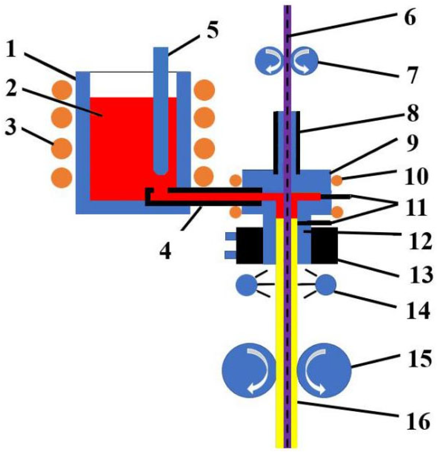
2. Experimental Procedure

This paper adopts the solid/liquid continuous composite casting technology, using 25 pure copper stranded wires as the core material, with brass (CuZn35) as the cladding, to produce a brass-clad copper stranded wire composite billet with a diameter of 16.5 mm. Figure 1 shows the process schematic for continuous casting of brass-clad copper stranded wire composite billets. The principle of the solid/liquid continuous composite casting process can be found in the literature. The preparation parameters used are as follows: the brass melt temperature in the composite chamber is 1035 °C, the continuous casting speed is 200–1000 mm/min, the cooling water flow rate of the crystallizer is 1000 L/h, and the continuous casting stop frequency is 90 times/min.
The prepared brass-clad copper stranded wire composites are shown in Figure 2(a1,a2). The composite material consists of pure copper strand wire (comprising 24 outer copper wires and 1 central copper wire) and an external brass cladding layer. The interface between the outer pure copper strand wire and the brass cladding layer is firmly bonded through metallurgical bonding, while the pure copper strand wires are connected to each other through mechanical bonding. The material exhibits excellent surface quality and can be directly subjected to cold drawing processing without the need for acid pickling, polishing, or other treatments. In order to investigate the evolution of the microstructure and properties of the composite material during the drawing process, the drawing process parameters are established as shown in Table 1. The composite material after drawing is shown in Figure 2(b1–d2).
Optical microscopy (OM, Zeiss Axio, Zeiss, Oberkochen, Germany), scanning electron microscopy (SEM, Regulus8100, Hitachi, Tokyo, Japan), electron backscatter diffraction (EBSD, JSM-7900F, JEOL Ltd., Tokyo, Japan), and transmission electron microscopy (TEM, Talos F200x, Thermo Fisher Scientific, Waltham, MA, USA) were used to observe the microstructure of brass-clad copper stranded wire composites prepared using different processes. The mechanical properties of the composite material were tested using an MTS universal testing machine (MTS Systems Corporation, Eden Praire, MA, USA). Three samples were tested for each state, and the average values of their performance were taken as the test results. The Vickers hardness of the brass-clad copper stranded wire composites was measured using an HXD-1000T hardness tester (Shandong Shancai Testing Instrument Co., Ltd., Yantai, China). Five points were measured for each sample, and the average value was taken as the test result.

3. Experimental Results

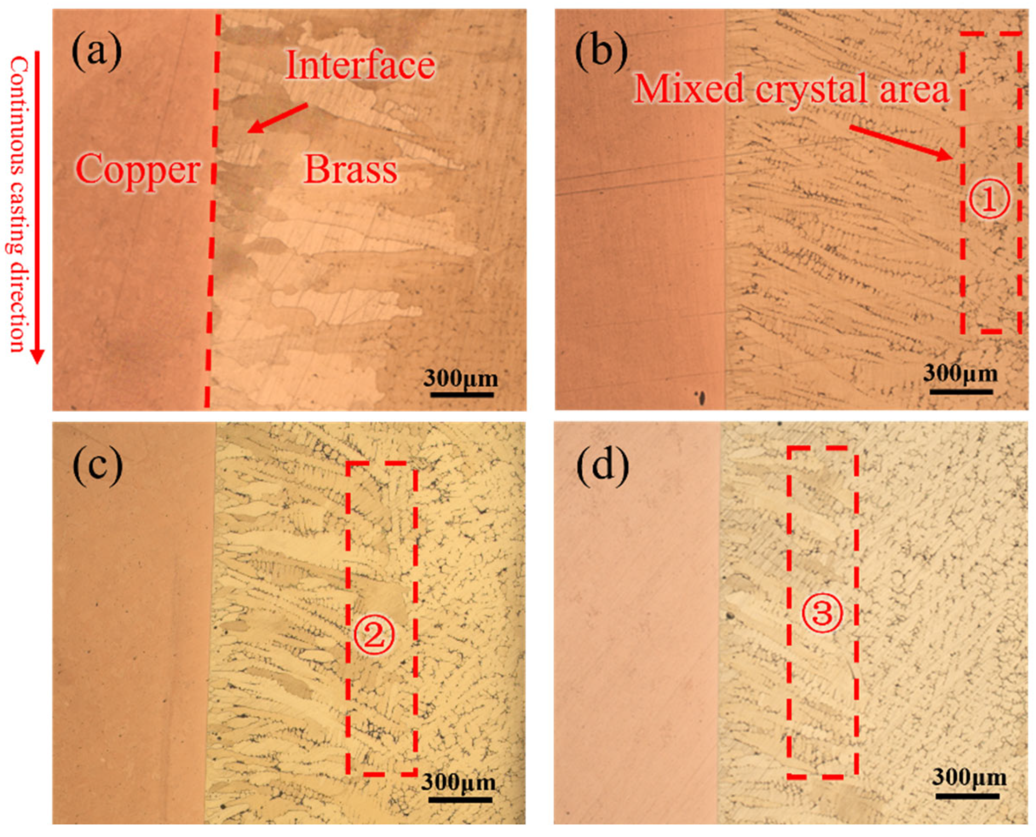
3.1. As-Cast Brass-Clad Copper Stranded Wire Composite Billet

Figure 3 illustrates the metallographic features of the longitudinal section of brass-clad copper strand wire composite billets at different continuous casting speeds (200–1000 mm/min). It can be seen that the interface between the brass and the copper achieves excellent metallurgical bonding. At a casting speed of 200 mm/min, the longitudinal section of the brass cladding layer primarily consists of columnar grains that are radially distributed. At 400 mm/min, the growth direction of the columnar grains forms an angle of approximately 15° with the radial direction, and the grain width of the columnar structure is significantly reduced. Additionally, a mixed grain region appears near the outer wall of the casting, as shown in Area ① of Figure 3b. At 800 mm/min, the angle between the columnar grains and the radial direction increases further to about 20°. The region of mixed grains with interlocking growth near the crystallizer side of the brass cladding layer begins to move inward. Fine equiaxed grains are also formed on the outer wall of the cladding layer due to the chilling effect of the crystallizer, as shown in Area ② of Figure 3c. At 1000 mm/min, the angle between the columnar grains and the radial direction increases to approximately 30°. The region of interlocking dendritic grains near the crystallizer side of the brass cladding layer extends further inward, as shown in Area ③ of Figure 3d.
Figure 4 presents the statistical results of grain size in the brass cladding layer at different continuous casting speeds. With the increase in casting speed, the length of columnar grains first increases and then decreases, while the width of columnar grains gradually decreases. At a casting speed of 200 mm/min, the width of the columnar grains is approximately 130 μm. When the casting speed increases from 300 mm/min to 700 mm/min, the width of the columnar grains decreases to around 80 μm. As the casting speed further increases to between 800 mm/min and 1000 mm/min, the width of the columnar grains is further reduced to approximately 70 μm. During the continuous casting and solidification process, at a low speed of 200 mm/min, the heat input is relatively high and the residence time is long, allowing grains to grow sufficiently. However, repeated melting and local remelting at the solidification front can disrupt the continuous growth of grains, thereby limiting their length. At speeds of 300–400 mm/min, the stability of the molten pool front is optimal. The solidification front advances steadily, providing a stable environment for grain growth, which allows the grains to reach their maximum length. With the casting speed increasing further, the solid–liquid interface advances more rapidly, leaving insufficient time for the grains to fully grow, resulting in the reduction in grain length. When the casting speed is relatively high (800–1000 mm/min), the solidification speed is fast, and the heat transfer direction is mainly along the grain length direction, while the heat transfer in the grain width direction is stable. This results in almost constant grain width.
Figure 5a,b show the SEM images of the interface of the brass-clad copper strand wire composite billet at a continuous casting speed of 300 mm/min, along with the corresponding EDS composition analysis results. From the images, it is evident that the interface between the brass and pure copper is well bonded, with a significant atomic diffusion of copper and zinc occurring on both sides of the interface, forming an interface diffusion layer approximately 26 μm thick. Figure 5c demonstrates that as the continuous casting speed increases, the thickness of the copper–zinc diffusion layer gradually decreases. The change in the diffusion layer thickness is closely related to the temperature field and solidification behavior during the continuous casting process. By examining the scanning images, it can be observed that regardless of whether the casting speed is low or high, a metallurgically well-bonded interface is formed in the brass-clad copper strand wire composite billet. This indicates that the continuous casting process can successfully produce a composite material with excellent metallurgical bonding at both low and high speeds.
Figure 6 illustrates the surface roughness of the brass-clad copper strand wire composite billet at different continuous casting speeds. From the figure, it can be observed that the radial roughness ranges from 4 to 7 μm across different casting speeds. The transverse roughness ranges from 30 to 40 μm. The overall surface quality is good across all conditions. Additionally, the shear strength of the brass-clad copper strand wire composite billet at different casting speeds is found to be between 130 and 170 MPa, indicating a relatively high shear strength. This is advantageous for reducing the likelihood of crack formation at the brass and copper interface during the drawing process. This combination of excellent surface quality and high shear strength ensures that the brass-clad copper strand wire composite billet can undergo subsequent cold processing without the need for additional polishing, acid washing, or other treatment steps. This not only improves the cold-working performance and yield of the composite wire but also reduces environmental contamination.

3.2. Evolution of Microstructure and Properties in Drawing Process

3.2.1. Mechanical Properties Evolution

During the drawing process, the strength, hardness, and work hardening rate of brass and pure copper are closely related to their deformation amount [7,8,9,10]. Figure 7 shows the variation in hardness and work hardening rate during the drawing process of the brass-coated copper wire. As shown in Figure 7a, with the increase in the drawing strain, the hardness of both the brass coating and the copper wire increases. The hardness and work hardening rate of the brass coating are significantly higher than those of the copper wire, and the hardness contrast between the layers increases. Moreover, the hardness of both the brass coating and the copper wire follows a similar trend with the increase in the total strain, which can be divided into the following three stages: (1) Total strain of 0–12.6%: The hardness of the brass coating and both the inner and outer copper wires increases significantly, and the work hardening rate is high. The hardnesses of the three materials increase from the initial values of 80 HV, 63 HV, and 59 HV for the composite wire, to 154 HV, 101 HV, and 87 HV, respectively. (2) Total strain of 12.6–78.8%: As the total strain increases, the rate of hardness increase slows down, and the work hardening rate tends to level off. At this point, the hardnesses of the brass coating, inner copper wire, and outer copper wire reach 236 HV, 118 HV, and 107 HV, respectively. (3) Total strain of 78.8–81.5%: As the strain increases further, the hardnesses of both the brass coating and the copper wires increase significantly, and the work hardening rate increases again. When the total strain reaches 81.5%, the hardnesses of the brass coating, inner copper wire, and outer copper wire reach 262 HV, 135 HV, and 143 HV, respectively. In Figure 7b, it can be seen that when the strain reaches 50%, the work hardening rates of the brass coating and copper wire become nearly identical, and they begin to exhibit good synergistic deformation characteristics. Even after large amounts of deformation, the interface still maintains good metallurgical bonding quality.
Figure 8 shows the variation trends of tensile strength, yield strength, and elongation after fracture of the brass-clad copper strand wire composites after drawing, as a function of total deformation. The tensile strength of the as-cast composite billet is 243 MPa, with an elongation after fracture of 49.1%. For a total deformation of 0–28.3%, the tensile strength of the composite wire increases almost linearly with increasing deformation, while the elongation after fracture decreases. At 11.9% total deformation, the tensile strength rises to 336 MPa, and the elongation decreases to 30.1%. At 28.3% total deformation, the tensile strength further increases to 404 MPa, and the elongation decreases to 13.1%. For a total deformation of 40.2–68.1%, the increase in tensile strength slows down, and the rate of decrease in elongation after fracture also reduces. At 68.1% total deformation, the tensile strength reaches 504 MPa, and the elongation decreases to 6.7%. For a total deformation of 73.4–81.5%, the tensile strength and elongation after fracture show little variation. At 81.5% total deformation, the tensile strength is 534 MPa, and the elongation after fracture is 4.7%. During the deformation process of the composite wire, both the pure copper stranded core and the brass cladding undergo significant work hardening. This work hardening leads to a linear increase in dislocation density, resulting in a nearly linear increase in the tensile strength of the composite wire with increasing deformation [11,12,13]. Moreover, the constitutive model for the composite is a potential direction for further research.
The brass-clad copper strand wire composites material is a bimetallic composite wire. Due to the significant difference in deformation behavior between the brass cladding layer and the pure copper strand wires, their synergistic deformation has a critical impact on the fracture behavior during the deformation process. Therefore, the fracture morphology of the composite wire during room temperature tensile testing was observed, and the results are shown in Figure 9. The tensile fracture of the as-cast wire exhibits a clear interface, the interface is indicated by the white dashed line in Figure 9a, with no interface cracks observed, indicating good bonding between the brass cladding layer and the pure copper strand wires and a relatively high bonding strength. In the pure copper strand wires, a large number of small and shallow dimples are present, while the dimples in the brass cladding layer are slightly larger. Both exhibit characteristics of typical ductile fracture. After drawing with different deformation amounts, no interface cracks were observed at the tensile fracture between the brass and copper. With increasing deformation, a large number of small and shallow dimples are observed at the fracture of the pure copper, characteristic of typical ductile fracture. On the other hand, the fracture of the brass cladding layer shows slightly larger dimples, along with an increased number of cleavage planes, indicating cleavage fracture behavior.

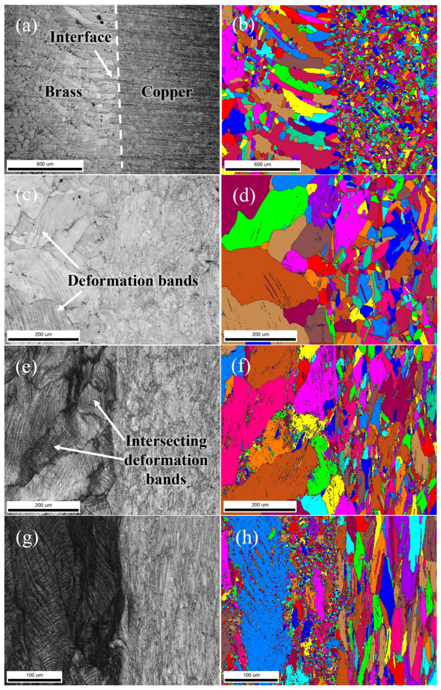
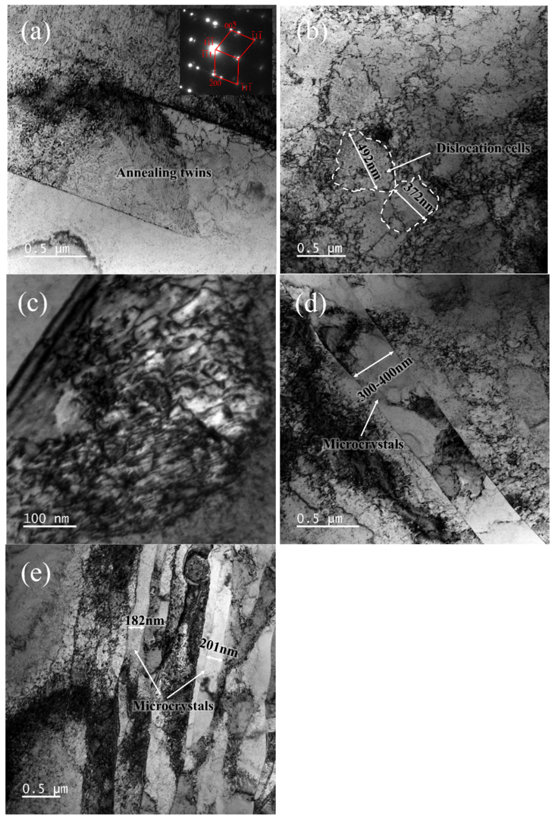
3.2.2. Microstructure Evolution

Figure 10 presents the EBSD contrast images and orientation imaging maps of the brass cladding layer and the pure copper strand wires in the longitudinal section of the brass-clad copper strand wire composite material. During the continuous casting and drawing processes, the microstructure of pure copper and brass undergoes significant changes [14,15,16,17]. Figure 10a shows that the brass cladding layer in the composite billet exhibits a columnar grain structure growing along the radial direction, while the pure copper strand wires display equiaxed grains with annealing twins inside some grains. Additionally, the interface between the brass cladding and the pure copper strand wires achieves excellent metallurgical bonding. During the continuous casting composite process, when the high-temperature brass melt comes into contact with the lower-temperature pure copper strand wires, the cooling effect of the pure copper strand wires creates a significant radial temperature gradient. This leads to the rapid solidification of the brass melt on the surface of the copper strand wires and promotes the growth of columnar grains along the radial direction, forming the characteristic radial columnar grain structure in the brass cladding layer. Meanwhile, the intense heating effect of the high-temperature brass melt causes the pure copper strand wires to heat up rapidly. This results in recrystallization and grain growth within the copper strand wires, forming the equiaxed grain structure. Due to the coarse grains and the elevated heating temperature, annealing twins are observed within some grains. During the deformation process, the brass has higher strength and tends to resist more deformation and thus bear higher stress, while the copper experiences relatively lower stress. Thus, stress concentration tends to occur near the interface between the two phases. In terms of strain, the copper undergoes larger plastic deformation, whereas the brass shows less plastic deformation. As a result, micro-displacements may occur at the phase boundaries. The above views need to be further verified by simulation or other methods.
In order to further study the microstructure evolution of brass-coated copper stranded wire composite billets during the drawing process, transmission electron microscopy (TEM) was used to observe the microstructure of the composite billets under various drawing conditions [18,19,20,21,22,23]. Figure 11 shows the TEM microstructure of the pure copper stranded wire in the composite billet. In the as-cast state (Figure 11a), typical annealing twins were observed within the grains of the pure copper stranded wire, along with a few dislocations. These dislocations were caused by the vacancy accumulation generated during the continuous casting process when the pure copper stranded wire was heated by the high-temperature brass melt. When the total drawing strain reached 11.9%, a large number of dislocations appeared in the pure copper wire grains, and dislocation interactions formed dislocation cells with diameters ranging from 350 to 500 nm (Figure 11b) [17,20,21,22]. When the total drawing strain reached 40.2%, the dislocation density in the pure copper stranded wire further increased, and the dislocations became tangled (Figure 11c). At a total drawing strain of 57.7%, elongated microcrystal structures with parallel distribution were observed in the pure copper stranded wire, with microcrystal widths ranging from 300 to 400 nm. These microcrystals contained a high density of dislocations (Figure 11d). When the total drawing strain reached 81.5%, the number of microcrystals in the pure copper stranded wire further increased, and the microcrystal width decreased to 150–250 nm (Figure 11e).
In the as-cast state, the brass coating layer shows a uniform contrast, exhibiting typical microstructure features of the as-cast condition (Figure 12a). When the total drawing strain reached 11.9%, a large number of diffusely distributed dislocation networks were observed in the brass coating, along with the formation of a small amount of deformation twins (Figure 12b). When the total drawing strain reached 40.2%, the number of deformation twins in the brass coating significantly increased, with twin widths around 8.5–10 nm (Figure 12c). At a total drawing strain of 57.7%, the number of deformation twins in the brass coating significantly increased, with their width reduced to 3–5 nm. The intersecting twins caused local lattice distortion to intensify (Figure 12d). Additionally, shear bands with different orientations were observed in the brass coating [20,21,22]. These shear bands intersected and passed through the deformation twins, forming intense shear deformation regions that caused noticeable crystal rotation in the local area [23,24,25,26,27]. Furthermore, high-density dislocation accumulation regions were found at the intersections of the shear bands (Figure 12d), indicating that these intersections were high strain regions. When the total drawing strain reached 81.5%, the number of dislocations and deformation twins in the brass coating significantly increased, with twin widths reduced to 2–4 nm (Figure 12e). The interaction of intersecting shear bands became more prominent, and secondary twins and high-density dislocations were observed within the wider primary twins. The strong interaction between the secondary twins and dislocations suggests that the brass coating has reached a highly deformed state (Figure 12e).
Shear bands typically refer to elongated, band-like microstructures that form within grains after the material has undergone a certain degree of plastic deformation. Once these shear bands form, the dislocation density within the grains increases sharply. The shear bands in different directions intersect and impede the further movement of dislocations. The formation of shear deformation bands is primarily related to the deformation behavior and material characteristics of brass. Brass has a face-centered cubic (FCC) crystal structure, and its plastic deformation mainly occurs through slip systems. During external loading, multiple slip systems may activate alternately, leading to the formation of shear bands with different orientations that intersect within the grains. This is the fundamental mechanism behind the formation of shear bands. The microstructural evolution of the brass cladding layer during the drawing process is generally consistent with that reported in the literature [10,11,12].
In summary, under different drawing conditions, the microstructure of the brass-clad copper strand wire composites exhibits complex patterns of dislocation evolution, twin formation, and shear deformation. These characteristics provide important experimental evidence for the in-depth study of the plastic deformation mechanisms of this material.

4. Discussion

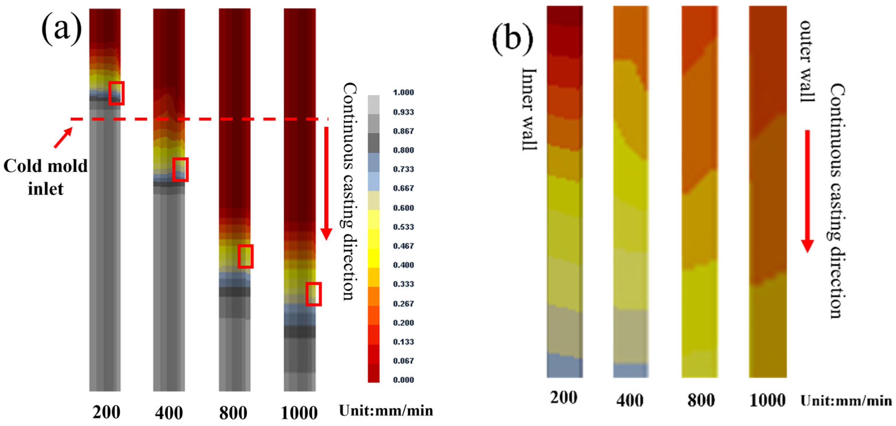
4.1. Effect of Continuous Casting Speeds on As-Cast Microstructure of Brass Cladding Layers and Kness of Interface Diffusion Layers

As the continuous casting speed increases from 200 mm/min to 1000 mm/min, the microstructure of the composite wire transitions from coarse radial columnar grains to fine, elongated columnar grains angled relative to the radial direction. At a casting speed of 200 mm/min, the brass solid–liquid interface is located at the upper end of the cold mold section. The brass melt at the front of the interface is minimally affected by the cold mold and is primarily cooled by the copper core. The heat transfer direction is mainly from the core toward the outer wall of the brass cladding, forming a significant radial temperature gradient. This results in the formation of columnar grains growing outward from the interface, as shown in Figure 3a. At a casting speed of 400 mm/min, the brass solid–liquid interface enters the cold mold section. Under the combined cooling effects of the cold mold and the copper core, the radial heat transfer direction near the interface shifts, causing the columnar grains to grow at an angle to the radial direction, as illustrated in Figure 3b. When the continuous casting speed increases to 800 mm/min, the strong chilling effect of the cold mold promotes the formation of numerous nuclei on the inner wall of the mold. These nuclei grow from the outer wall toward the center of the copper core, developing into a mixed grain structure, as shown in Figure 3c. At a casting speed of 1000 mm/min, the intense chilling effect of the cold mold causes a significant amount of nucleation on the inner wall of the mold. The mixed grain region gradually shifts inward toward the brass cladding, as shown in Figure 3d. As the solid–liquid interface moves closer to the cold mold section, the cooling effect on the brass melt becomes stronger. Consequently, with increasing casting speed, the grain width progressively decreases. To further study the effect of continuous casting speed on the solidification process of brass-clad copper strand wire composite billet, numerical simulations of the temperature field were conducted for casting speeds of 200 mm/min, 400 mm/min, 800 mm/min, and 1000 mm/min. The results are shown in Figure 13.
Figure 13a shows the simulated temperature field of the brass cladding layer during the solidification process, while Figure 13b provides a magnified view of the longitudinal cross-sectional region from the inner wall to the outer wall, corresponding to the red boxed area in Figure 13a. It can be observed that as the casting speed increases from 200 mm/min to 1000 mm/min, the solid–liquid interface progressively moves deeper into the cold mold section. The further the solid–liquid interface enters the cold mold section, the more significant the cooling effect of the cold mold on the brass melt becomes. At casting speeds of 200–400 mm/min, the solid–liquid interface is located in the upper part of the cold mold section. In this case, the temperature of the inner side of the casting sample decreases rapidly, and the cooling effect of the pure copper strand wires dominates. This leads to the brass melt near the pure copper strand wires solidifying first. At casting speeds of 800–1000 mm/min, the solid–liquid interface has fully entered the cold mold section. At this stage, the temperature on the cold mold side decreases more rapidly, and the cooling effect of the cold mold surpasses that of the pure copper strand wires. Due to the combined cooling effect of the cold mold and the pure copper strand wires, a mixed grain structure forms in the region near the outer wall of the brass cladding layer.
As the continuous casting speed increases further, the cooling effect of the cold mold intensifies, causing the mixed grain region to gradually extend toward the inner wall of the brass cladding layer. The simulated temperature field results described above align well with the metallographic observations of the microstructure shown in Figure 3. Table 2 presents the temperature gradient, solidification rate, and the product of the two during the solidification process of the brass-clad copper strand wire composite billet under different casting speeds. As the casting speed increases, the temperature gradient decreases slightly, while the solidification rate increases significantly. The product of the temperature gradient and the solidification rate continuously rise with increasing casting speed. The product of the temperature gradient and the solidification rate has a significant influence on the scale of the solidified microstructure. A larger product results in a finer solidified microstructure, while a smaller product results in coarser structures. As the casting speed increases, the product increases, leading to a reduction in the size of the solidified microstructure. As the continuous casting speed increases, the solidification rate of the brass cladding layer also increases, as shown in Table 2. This results in a shorter diffusion time for zinc atoms from the brass melt into the pure copper core, thereby leading to a reduction in the thickness of the copper–zinc diffusion layer.
This observation is consistent with the experimental results of the continuous casting process for the composite stranded wire (Figure 4 and Figure 5c) and the simulation results.

4.2. Relationship Between Microstructure and Mechanical Properties in Drawing Process

During the cold drawing process of the brass-clad copper strand wire composites, significant changes occurred in the microstructure of the brass cladding layer and the pure copper strand wires as the drawing deformation increased. These changes have a critical impact on the strength, hardness, and elongation after fracture of the composite wire. The main changes observed with increasing deformation are as follows: When the drawing deformation reaches 11.9%, as shown in Figure 11b and Figure 12b, the dislocation density in both the brass cladding layer and the pure copper strand wires rises sharply. Dislocation cells appear in the pure copper strand wires, while deformation bands are observed in the brass cladding layer (Figure 10c).
At this stage, the strength and hardness of the brass cladding layer and the pure copper strand wires increase significantly, showing a high work hardening rate, while the elongation after fracture decreases noticeably. When the deformation increases to 57.7%, as shown in Figure 11c and Figure 12c, the growth rate of dislocation density in both the pure copper strand wires and the brass cladding layer slows down. Microcrystals with sizes of 300–400 nm appear in the pure copper strand wires, while deformation twins are observed in the brass cladding layer. At this point, the strength and hardness of the brass cladding layer and the pure copper strand wires continue to increase gradually, plasticity decreases, and the work hardening rate begins to level off. When the drawing deformation reaches 81.5%, as shown in Figure 11e and Figure 12e, the microcrystal size in the pure copper strand wires decreases further, and the number of microcrystals increases. In the brass cladding layer, intersecting shear bands appear, accompanied by dislocation pile-ups and secondary twins near the shear bands. At this stage, with further increases in deformation, the strength and hardness of the brass cladding layer and pure copper strand wires show a significant increase, and the work hardening rate rises again. In summary, the brass cladding layer and pure copper strand wires exhibit excellent synergistic deformation characteristics during the drawing process. Even after undergoing large amounts of deformation, the interface between the two materials maintains excellent metallurgical bonding quality.

4.3. Technology Application

All in all, the brass-clad copper stranded wire composite was successfully prepared under industrial conditions using a solid–liquid continuous casting composite–cold drawing process. It was found that as-cast billets could be prepared in high quality under continuous casting speeds ranging from 200 mm/min to 1000 mm/min. However, in order to improve production efficiency in actual production, it is recommended to carry out continuous casting at a speed of 800–1000 mm/min. As shown in Figure 14, on the basis of the above study, the key technology of continuity, stability, consistency, and high-speed continuous composite casting was broken through, and a high-quality composite wire production line with an annual output of 10,000 km was built to produce the developed serialized brass-clad copper stranded wire composites.

5. Conclusions

Using a solid–liquid continuous composite casting and drawing process, brass-clad copper stranded wires were successfully prepared under the industrial condition. The main conclusions are as follows:
(1)
When the casting speed increased from 200 mm/min to 1000 mm/min, the microstructure of the brass cladding transformed from radial columnar grains to columnar grains angled relative to the radial direction.
(2)
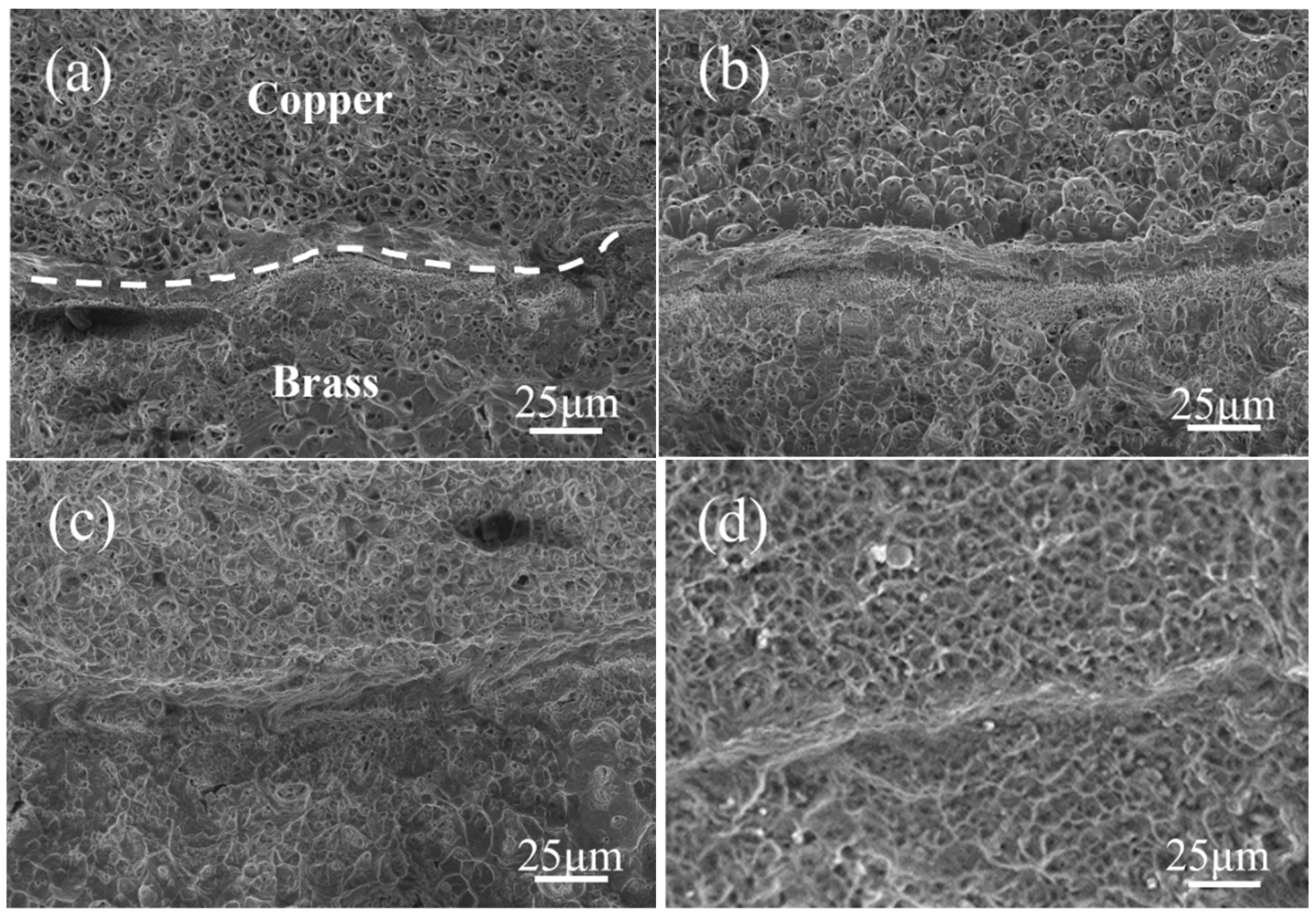
The shear strength of the brass-clad copper stranded wire composites under different casting speeds ranged from 130 to 170 MPa, demonstrating excellent metallurgical bonding quality at the interface between the brass cladding and the pure copper strand wires.
(3)
As the total deformation increased from 11.9 to 81.5%, the tensile strength increased from 334 to 534 MPa. The primary deformation mechanism of the copper stranded wires was dislocation slip, while that of the brass cladding progressed from dislocation planar slip to deformation twinning and finally to shear deformation.

Author Contributions

Conceptualization, Y.J., F.Z., X.L. (Xinhua Liu) and J.X.; methodology, Y.L. and X.L. (Xiao Liu); validation, Y.L. and X.L. (Xiao Liu); investigation, Y.L. and X.L. (Xiao Liu); data curation, Y.L. and X.L. (Xiao Liu); writing—original draft preparation, Y.L. and X.L. (Xiao Liu); writing—review and editing, Y.J., F.Z., X.L. (Xinhua Liu) and J.X.; supervision, X.L. (Xinhua Liu); funding acquisition, X.L. (Xinhua Liu) and F.Z. All authors have read and agreed to the published version of the manuscript.

Funding

This research was supported by the National Natural Science Foundation of China (grant number: 51925401) and the Young Elite Scientists Sponsorship Program by CAST (grant number: 2022QNRC001).

Data Availability Statement

The original contributions presented in this study are included in the article. Further inquiries can be directed to the corresponding author.

Conflicts of Interest

The authors declare no conflict of interest.

References

  1. Sang, T.; Zheng, Q.; Zhang, J.; Xia, W. The application research of the railway through-line groundwire. Electr. Wire Cable 2019, 5, 14–16. (In Chinese) [Google Scholar]
  2. Yang, B.; Hei, G.; Li, J. The structure improvement for railway composite through-line ground wire. Electr. Wire Cable 2016, 5, 8–11, 44. (In Chinese) [Google Scholar]
  3. Ding, X. The application of the continuous aluminium extruding cosnform to produce Al alloy-sheathed through-railway ground wire. Electr. Wire Cable 2007, 4, 19–20, 23. (In Chinese) [Google Scholar]
  4. Li, C.; Zhang, T.A.; Liu, Y.; Liu, J. Effect of process parameters on surface quality and bonding quality of brass cladding copper stranded wire prepared by continuous pouring process for clad. J. Mater. Res. Technol. 2023, 26, 8025–8035. [Google Scholar] [CrossRef]
  5. Jiang, Y.; Ling, L.; Xie, J. Influences of preparing parameters on surface quality and interface bonding state of brass cladding copper stranded wire by inversion solidification. Chin. J. Nonferrous Met. 2018, 28, 693–704. (In Chinese) [Google Scholar]
  6. Wang, J.; Zhao, F.; Wang, R.; Liu, X. Preparation and properties of copper-aluminum composite strips and foils by horizontal continuous composite casting and rolling. J. Mater. Process. Technol. 2023, 322, 118168. [Google Scholar] [CrossRef]
  7. Gaurav; Chakraborty, P.; Vejendla, S.B.P. Deformation and annealing of brass. Mater. Today Proc. 2022, 64, 1380–1383. [Google Scholar] [CrossRef]
  8. Wang, X.; Xiao, Z.; Zhou, T.; Jiang, X. Deformation mechanism and properties evolution of a copper alloy with ultra-high strength after cold drawing and subsequent aging treatment. Mater. Sci. Eng. A 2024, 912, 146952. [Google Scholar] [CrossRef]
  9. Hu, M.; Liu, C.; Zhang, X.; Chen, H.; Gan, X. Deformation mechanisms of the Cu-15Ni-8Sn-0.18Nb alloy in as-quenched and aged conditions. Mater. Sci. Eng. A 2025, 919, 147477. [Google Scholar] [CrossRef]
  10. Han, P.C.; Tao, N.R. Effect of deformation mechanisms on the strength-ductility trade-off of Cu and CuAl alloy. Scr. Mater. 2022, 212, 114559. [Google Scholar] [CrossRef]
  11. Zhou, S.; Lv, W.; Li, P.; Gong, Y.; Tao, J.; Cheng, L.; Zhu, X. Mechanical properties and deformation kinetics of bulk Cu–Al–Zn alloy subjected to rolling and annealing. Mater. Sci. Eng. A 2014, 609, 217–221. [Google Scholar] [CrossRef]
  12. Li, Y.; Kog, N.; Watanabe, C.; Miura, H. Microstructures and mechanical properties of Cu 38 mass%Zn alloy fabricated by different rolling pass schedules. Mater. Trans. 2022, 63, 497–501. [Google Scholar] [CrossRef]
  13. Sun, Q.; Sun, J.; Fu, Y.; Xu, B.; Han, Y.; Chen, J.; Han, J.; Wu, H.; Wu, G. Preparing thick gradient surface layer in Cu-Zn alloy via ultrasonic severe surface rolling for strengthductility balance. Materials 2022, 15, 7687. [Google Scholar] [CrossRef] [PubMed]
  14. Cho, C.; Son, K.; Cho, H. Experimental analysis of deformation texture evolutions in pure Cu, Cu-37Zn, Al-6Mg, and −8Mg alloys at cold-rolling processes. J. Alloys Compd. 2023, 934, 167879. [Google Scholar] [CrossRef]
  15. Xin, G.; Zhou, M.; Jing, K.; Hu, H.; Li, Z.; Zhang, Y.; Tian, C.; Sun, Y.; Tian, B.; Li, X.; et al. Hot deformation behavior and microstructure evolution of the Cu-1.5Ti-(0.5Fe) alloys. J. Mater. Res. Technol. 2024, 30, 4961–4972. [Google Scholar] [CrossRef]
  16. Wu, H.; Huang, T.; Song, K.; Zhou, Y.; Li, S.; Zhang, Y. Effect of large deformation on microstructure and properties of copper alloy wire. J. Mater. Res. Technol. 2024, 29, 5136–5148. [Google Scholar] [CrossRef]
  17. Yadong, R.; Zhongyuan, Z.; Zhaoshun, G.; Ling, Z.; Tingting, Z.; Jiangli, X.; Zhixiang, T.; Bo, D.; Yongsheng, L.; Liye, X. Effect of plastic deformation on microstructure and properties of Cu-(1 wt%–6 wt%) Ag alloy. J. Wuhan. Univ. Technol. Mater. 2024, 39, 747–753. [Google Scholar]
  18. Yi, F. Principal shear bands in metal plastic deformation. Sci. China Ser. E Technol. Sci. 1998, 41, 661–665. [Google Scholar] [CrossRef]
  19. Yanchuan, T.; Juwen, X.; Zeyun, C.; Wenhui, W.; Xinlei, Z.; Xingchang, T.; Longzhi, Z. Cold rolling deformation behavior and interface transition layer evolution of Cu-Be/Cu-Zn laminated composite. Mater. Rep. 2021, 35, 1177–1182. (In Chinese) [Google Scholar]
  20. Basor, I.; Gadhu, R.; Sofyan, B.T. Effects of deformation and annealing temperature on the Microstructures and Hardness of Cu-29Zn-0.6Bi Brass. Key Eng. Mater. 2017, 748, 218–223. [Google Scholar]
  21. Tarasov, S.Y.; Filippov, A.V.; Fortuna, S.V.; Vorontsov, A.V. Microstructure and tensile properties of Cu–Zn brass after severe plastic deformation. In Proceedings of the Advanced Materials with Hierarchical Structure for New Technologies and Reliable Structures, Tomsk, Russia, 1–5 October 2018; Volume 2051, p. 20301. [Google Scholar]
  22. Pokharel, R.; Niu, T.; Ricci, S.; Clausen, B.; Balogh, L.; Ravkov, L.; Martinez, R.; Lee, C.; Vogel, S.; Cady, C.M.; et al. Alloying effects on deformation induced microstructure evolution in copper. Sci. Rep. 2024, 14, 23915. [Google Scholar] [CrossRef] [PubMed]
  23. Bodyakova, A.; Tkachev, M.; Pilipenko, A.; Belyakov, A.; Kaibyshev, R. Effect of deformation methods on microstructure, texture, and properties of a Cu–Mg alloy. Mater. Sci. Eng. A 2023, 876, 145126. [Google Scholar] [CrossRef]
  24. Jiang, K.; Zhou, Y.; Yang, R.; Song, K.; Liu, Y.; Zhang, Y.; Yang, S.; Zhou, F.; Huang, K.; Liu, D.; et al. Effects of cold deformation and aging on the phase transformation and mechanical properties of a Cu-15Ni-8Sn alloy. Mater. Charact. 2024, 210, 113796. [Google Scholar]
  25. Li, X.; Jing, K.; Zhou, M.; Chu, C.; Zhang, Y.; Tian, B.; Liu, Y.; Zhang, Q.; He, W.; Ma, S. Microstructure and hot deformation behavior of the Cu-0.3Zr(−0.2Mg) alloys. Mater. Today Commun. 2025, 42, 111539. [Google Scholar] [CrossRef]
  26. Morozova, A.; Tkachev, M.; Pilipenko, A.; Lugovskaya, A.; Belyakov, A.; Kaibyshev, R. Effect of the deformation temperature on the deformation behavior of a Cu-Cr-Zr alloy. Mater. Sci. Eng. 2021, 1014, 12033. [Google Scholar] [CrossRef]
  27. Gu, C.F.; Toth, L.S.; Zhang, Y.D.; Hoffman, M. Unexpected brass-type texture in rolling of ultrafine-grained copper. Scr. Mater. 2014, 92, 51–54. [Google Scholar] [CrossRef]
Figure 1. Process schematic for preparation of brass-clad copper stranded wire composite billet: 1—melting crucible; 2—brass liquid for cladding layer; 3, 10—crucible heater; 4—flow guiding tube; 5—plug rod; 6—copper stranded wire; 7—core guiding device; 8—core protection; 9—heating mold; 11—temperature measurement devices; 12—cooling mold; 13—crystallizer; 14—secondary cooling device; 15—drawing device; 16—brass-clad copper stranded wire composite billet.
Metals 15 00482 g001
Figure 2. Macro images of brass-clad copper stranded wire composites under as-cast and various drawing deformation conditions: (a1,a2) as-cast; (b1,b2) 11.9%; (c1,c2) 40.2%; (d1,d2) 81.5%.
Metals 15 00482 g002
Figure 3. Metallographic images of longitudinal section of brass-clad copper stranded wire composite billets at different continuous casting speeds: (a) 200 mm/min; (b) 400 mm/min; (c) 800 mm/min; (d) 1000 mm/min.
Metals 15 00482 g003
Figure 4. Variation in grain size of brass cladding layer at different continuous casting speeds: (a) grain length; (b) grain width.
Metals 15 00482 g004
Figure 5. SEM images and diffusion layer thickness statistics of brass-clad copper strand wire composite billet: (a) scanning image of diffusion zone in composite wire; (b) element diffusion map; (c) diffusion layer thickness at different continuous casting speeds.
Metals 15 00482 g005
Figure 6. Surface roughness of brass-clad copper strand wire composite billet at different continuous casting speeds.
Metals 15 00482 g006
Figure 7. Hardness and work hardening rate of brass and copper strand wire at different drawing deformation amounts: (a) hardness; (b) work hardening rate.
Metals 15 00482 g007
Figure 8. Mechanical properties of brass-clad copper strand wire composites at different drawing deformation amounts.
Metals 15 00482 g008
Figure 9. Tensile fracture morphology of brass-clad copper strand wire composites at different deformation amounts: (a) as-cast; (b) 11.9%; (c) 40.2%; (d) 81.5%.
Metals 15 00482 g009
Figure 10. EBSD contrast images and orientation imaging maps of longitudinal section of composite wire in as-cast and drawn states at different deformation amounts: (a,b) as-cast; (c,d) 11.9%; (e,f) 40.2%; (g,h) 57.7%; (i,j) 81.5%.
Metals 15 00482 g010aMetals 15 00482 g010b
Figure 11. TEM Images of pure copper strand wires in composite wire under as-cast and various drawing deformation conditions: (a) as-cast; (b) 11.9%; (c) 40.2%; (d) 57.7%; (e) 81.5%.
Metals 15 00482 g011
Figure 12. TEM images of brass cladding layer in wire composites under as-cast and various total drawing deformation conditions: (a) as-cast; (b) 11.9%; (c) 40.2%; (d) 57.7%; (e) 81.5%.
Metals 15 00482 g012
Figure 13. Temperature field simulation of brass cladding layer under different continuous casting speeds: (a) overall temperature field; (b) enlarged view of red boxes in (a).
Metals 15 00482 g013
Figure 14. (a) Overall view of composite wire production line; (b) multi-flow continuous composite casting equipment; (c) composite wire product after drawing; (d) cross-sections of serialized brass-clad copper stranded wire composites.
Metals 15 00482 g014
Table 1. Drawing process for brass-clad copper stranded wire composite billet.
Drawing PassOuter Diameter/mmPercentage Reduction in Area of this Pass/%Total Percentage
Reduction in Area
Reduction/%
016.300
115.311.911.9
213.818.628.3
312.616.640.2
411.516.750.2
510.615.057.7
69.224.768.1
78.416.673.4
88.09.375.9
97.512.178.8
107.012.981.5
Table 2. Solidification parameters of brass-clad copper strand wire composite billet at different continuous casting speeds.
Casting Speed/mm/min2004008001000
Temperature Gradient (TG)/°C/mm2.862.722.021.91
Solidification Rate (SR)/°C/s9.5018.3023.5331.80
TG × SR27.1449.7547.5160.71
Note: The mean TG and SR were calculated between the liquidus temperature point (887 °C) and the solidus temperature point (803 °C).
Disclaimer/Publisher’s Note: The statements, opinions and data contained in all publications are solely those of the individual author(s) and contributor(s) and not of MDPI and/or the editor(s). MDPI and/or the editor(s) disclaim responsibility for any injury to people or property resulting from any ideas, methods, instructions or products referred to in the content.

